EP2315301A1 - Power supply device and method for controlling charging/discharging operation of power supply device - Google Patents
Power supply device and method for controlling charging/discharging operation of power supply device Download PDFInfo
- Publication number
- EP2315301A1 EP2315301A1 EP10013709A EP10013709A EP2315301A1 EP 2315301 A1 EP2315301 A1 EP 2315301A1 EP 10013709 A EP10013709 A EP 10013709A EP 10013709 A EP10013709 A EP 10013709A EP 2315301 A1 EP2315301 A1 EP 2315301A1
- Authority
- EP
- European Patent Office
- Prior art keywords
- charging
- discharging
- power supply
- supply device
- battery pack
- Prior art date
- Legal status (The legal status is an assumption and is not a legal conclusion. Google has not performed a legal analysis and makes no representation as to the accuracy of the status listed.)
- Withdrawn
Links
Images




Classifications
-
- B—PERFORMING OPERATIONS; TRANSPORTING
- B60—VEHICLES IN GENERAL
- B60L—PROPULSION OF ELECTRICALLY-PROPELLED VEHICLES; SUPPLYING ELECTRIC POWER FOR AUXILIARY EQUIPMENT OF ELECTRICALLY-PROPELLED VEHICLES; ELECTRODYNAMIC BRAKE SYSTEMS FOR VEHICLES IN GENERAL; MAGNETIC SUSPENSION OR LEVITATION FOR VEHICLES; MONITORING OPERATING VARIABLES OF ELECTRICALLY-PROPELLED VEHICLES; ELECTRIC SAFETY DEVICES FOR ELECTRICALLY-PROPELLED VEHICLES
- B60L58/00—Methods or circuit arrangements for monitoring or controlling batteries or fuel cells, specially adapted for electric vehicles
- B60L58/10—Methods or circuit arrangements for monitoring or controlling batteries or fuel cells, specially adapted for electric vehicles for monitoring or controlling batteries
- B60L58/12—Methods or circuit arrangements for monitoring or controlling batteries or fuel cells, specially adapted for electric vehicles for monitoring or controlling batteries responding to state of charge [SoC]
- B60L58/14—Preventing excessive discharging
-
- H—ELECTRICITY
- H02—GENERATION; CONVERSION OR DISTRIBUTION OF ELECTRIC POWER
- H02J—ELECTRIC POWER NETWORKS; CIRCUIT ARRANGEMENTS OR SYSTEMS FOR SUPPLYING OR DISTRIBUTING ELECTRIC POWER; SYSTEMS FOR STORING ELECTRIC ENERGY
- H02J7/00—Circuit arrangements for charging or discharging batteries or for supplying loads from batteries
-
- B—PERFORMING OPERATIONS; TRANSPORTING
- B60—VEHICLES IN GENERAL
- B60K—ARRANGEMENT OR MOUNTING OF PROPULSION UNITS OR OF TRANSMISSIONS IN VEHICLES; ARRANGEMENT OR MOUNTING OF PLURAL DIVERSE PRIME-MOVERS IN VEHICLES; AUXILIARY DRIVES FOR VEHICLES; INSTRUMENTATION OR DASHBOARDS FOR VEHICLES; ARRANGEMENTS IN CONNECTION WITH COOLING, AIR INTAKE, GAS EXHAUST OR FUEL SUPPLY OF PROPULSION UNITS IN VEHICLES
- B60K6/00—Arrangement or mounting of plural diverse prime-movers for mutual or common propulsion, e.g. hybrid propulsion systems comprising electric motors and internal combustion engines
- B60K6/20—Arrangement or mounting of plural diverse prime-movers for mutual or common propulsion, e.g. hybrid propulsion systems comprising electric motors and internal combustion engines the prime-movers consisting of electric motors and internal combustion engines, e.g. HEVs
- B60K6/42—Arrangement or mounting of plural diverse prime-movers for mutual or common propulsion, e.g. hybrid propulsion systems comprising electric motors and internal combustion engines the prime-movers consisting of electric motors and internal combustion engines, e.g. HEVs characterised by the architecture of the hybrid electric vehicle
- B60K6/46—Series type
-
- B—PERFORMING OPERATIONS; TRANSPORTING
- B60—VEHICLES IN GENERAL
- B60L—PROPULSION OF ELECTRICALLY-PROPELLED VEHICLES; SUPPLYING ELECTRIC POWER FOR AUXILIARY EQUIPMENT OF ELECTRICALLY-PROPELLED VEHICLES; ELECTRODYNAMIC BRAKE SYSTEMS FOR VEHICLES IN GENERAL; MAGNETIC SUSPENSION OR LEVITATION FOR VEHICLES; MONITORING OPERATING VARIABLES OF ELECTRICALLY-PROPELLED VEHICLES; ELECTRIC SAFETY DEVICES FOR ELECTRICALLY-PROPELLED VEHICLES
- B60L3/00—Electric devices on electrically-propelled vehicles for safety purposes; Monitoring operating variables, e.g. speed, deceleration or energy consumption
- B60L3/0023—Detecting, eliminating, remedying or compensating for drive train abnormalities, e.g. failures within the drive train
- B60L3/0046—Detecting, eliminating, remedying or compensating for drive train abnormalities, e.g. failures within the drive train relating to electric energy storage systems, e.g. batteries or capacitors
-
- B—PERFORMING OPERATIONS; TRANSPORTING
- B60—VEHICLES IN GENERAL
- B60L—PROPULSION OF ELECTRICALLY-PROPELLED VEHICLES; SUPPLYING ELECTRIC POWER FOR AUXILIARY EQUIPMENT OF ELECTRICALLY-PROPELLED VEHICLES; ELECTRODYNAMIC BRAKE SYSTEMS FOR VEHICLES IN GENERAL; MAGNETIC SUSPENSION OR LEVITATION FOR VEHICLES; MONITORING OPERATING VARIABLES OF ELECTRICALLY-PROPELLED VEHICLES; ELECTRIC SAFETY DEVICES FOR ELECTRICALLY-PROPELLED VEHICLES
- B60L50/00—Electric propulsion with power supplied within the vehicle
- B60L50/50—Electric propulsion with power supplied within the vehicle using propulsion power supplied by batteries or fuel cells
- B60L50/60—Electric propulsion with power supplied within the vehicle using propulsion power supplied by batteries or fuel cells using power supplied by batteries
- B60L50/61—Electric propulsion with power supplied within the vehicle using propulsion power supplied by batteries or fuel cells using power supplied by batteries by batteries charged by engine-driven generators, e.g. series hybrid electric vehicles
-
- B—PERFORMING OPERATIONS; TRANSPORTING
- B60—VEHICLES IN GENERAL
- B60L—PROPULSION OF ELECTRICALLY-PROPELLED VEHICLES; SUPPLYING ELECTRIC POWER FOR AUXILIARY EQUIPMENT OF ELECTRICALLY-PROPELLED VEHICLES; ELECTRODYNAMIC BRAKE SYSTEMS FOR VEHICLES IN GENERAL; MAGNETIC SUSPENSION OR LEVITATION FOR VEHICLES; MONITORING OPERATING VARIABLES OF ELECTRICALLY-PROPELLED VEHICLES; ELECTRIC SAFETY DEVICES FOR ELECTRICALLY-PROPELLED VEHICLES
- B60L58/00—Methods or circuit arrangements for monitoring or controlling batteries or fuel cells, specially adapted for electric vehicles
- B60L58/10—Methods or circuit arrangements for monitoring or controlling batteries or fuel cells, specially adapted for electric vehicles for monitoring or controlling batteries
- B60L58/12—Methods or circuit arrangements for monitoring or controlling batteries or fuel cells, specially adapted for electric vehicles for monitoring or controlling batteries responding to state of charge [SoC]
- B60L58/13—Maintaining the SoC within a determined range
-
- B—PERFORMING OPERATIONS; TRANSPORTING
- B60—VEHICLES IN GENERAL
- B60L—PROPULSION OF ELECTRICALLY-PROPELLED VEHICLES; SUPPLYING ELECTRIC POWER FOR AUXILIARY EQUIPMENT OF ELECTRICALLY-PROPELLED VEHICLES; ELECTRODYNAMIC BRAKE SYSTEMS FOR VEHICLES IN GENERAL; MAGNETIC SUSPENSION OR LEVITATION FOR VEHICLES; MONITORING OPERATING VARIABLES OF ELECTRICALLY-PROPELLED VEHICLES; ELECTRIC SAFETY DEVICES FOR ELECTRICALLY-PROPELLED VEHICLES
- B60L58/00—Methods or circuit arrangements for monitoring or controlling batteries or fuel cells, specially adapted for electric vehicles
- B60L58/10—Methods or circuit arrangements for monitoring or controlling batteries or fuel cells, specially adapted for electric vehicles for monitoring or controlling batteries
- B60L58/12—Methods or circuit arrangements for monitoring or controlling batteries or fuel cells, specially adapted for electric vehicles for monitoring or controlling batteries responding to state of charge [SoC]
- B60L58/15—Preventing overcharging
-
- B—PERFORMING OPERATIONS; TRANSPORTING
- B60—VEHICLES IN GENERAL
- B60L—PROPULSION OF ELECTRICALLY-PROPELLED VEHICLES; SUPPLYING ELECTRIC POWER FOR AUXILIARY EQUIPMENT OF ELECTRICALLY-PROPELLED VEHICLES; ELECTRODYNAMIC BRAKE SYSTEMS FOR VEHICLES IN GENERAL; MAGNETIC SUSPENSION OR LEVITATION FOR VEHICLES; MONITORING OPERATING VARIABLES OF ELECTRICALLY-PROPELLED VEHICLES; ELECTRIC SAFETY DEVICES FOR ELECTRICALLY-PROPELLED VEHICLES
- B60L58/00—Methods or circuit arrangements for monitoring or controlling batteries or fuel cells, specially adapted for electric vehicles
- B60L58/10—Methods or circuit arrangements for monitoring or controlling batteries or fuel cells, specially adapted for electric vehicles for monitoring or controlling batteries
- B60L58/18—Methods or circuit arrangements for monitoring or controlling batteries or fuel cells, specially adapted for electric vehicles for monitoring or controlling batteries of two or more battery modules
-
- B—PERFORMING OPERATIONS; TRANSPORTING
- B60—VEHICLES IN GENERAL
- B60L—PROPULSION OF ELECTRICALLY-PROPELLED VEHICLES; SUPPLYING ELECTRIC POWER FOR AUXILIARY EQUIPMENT OF ELECTRICALLY-PROPELLED VEHICLES; ELECTRODYNAMIC BRAKE SYSTEMS FOR VEHICLES IN GENERAL; MAGNETIC SUSPENSION OR LEVITATION FOR VEHICLES; MONITORING OPERATING VARIABLES OF ELECTRICALLY-PROPELLED VEHICLES; ELECTRIC SAFETY DEVICES FOR ELECTRICALLY-PROPELLED VEHICLES
- B60L58/00—Methods or circuit arrangements for monitoring or controlling batteries or fuel cells, specially adapted for electric vehicles
- B60L58/10—Methods or circuit arrangements for monitoring or controlling batteries or fuel cells, specially adapted for electric vehicles for monitoring or controlling batteries
- B60L58/24—Methods or circuit arrangements for monitoring or controlling batteries or fuel cells, specially adapted for electric vehicles for monitoring or controlling batteries for controlling the temperature of batteries
-
- B—PERFORMING OPERATIONS; TRANSPORTING
- B60—VEHICLES IN GENERAL
- B60W—CONJOINT CONTROL OF VEHICLE SUB-UNITS OF DIFFERENT TYPE OR DIFFERENT FUNCTION; CONTROL SYSTEMS SPECIALLY ADAPTED FOR HYBRID VEHICLES; ROAD VEHICLE DRIVE CONTROL SYSTEMS FOR PURPOSES NOT RELATED TO THE CONTROL OF A PARTICULAR SUB-UNIT
- B60W10/00—Conjoint control of vehicle sub-units of different type or different function
- B60W10/04—Conjoint control of vehicle sub-units of different type or different function including control of propulsion units
- B60W10/06—Conjoint control of vehicle sub-units of different type or different function including control of propulsion units including control of combustion engines
-
- B—PERFORMING OPERATIONS; TRANSPORTING
- B60—VEHICLES IN GENERAL
- B60W—CONJOINT CONTROL OF VEHICLE SUB-UNITS OF DIFFERENT TYPE OR DIFFERENT FUNCTION; CONTROL SYSTEMS SPECIALLY ADAPTED FOR HYBRID VEHICLES; ROAD VEHICLE DRIVE CONTROL SYSTEMS FOR PURPOSES NOT RELATED TO THE CONTROL OF A PARTICULAR SUB-UNIT
- B60W10/00—Conjoint control of vehicle sub-units of different type or different function
- B60W10/04—Conjoint control of vehicle sub-units of different type or different function including control of propulsion units
- B60W10/08—Conjoint control of vehicle sub-units of different type or different function including control of propulsion units including control of electric propulsion units, e.g. motors or generators
-
- B—PERFORMING OPERATIONS; TRANSPORTING
- B60—VEHICLES IN GENERAL
- B60W—CONJOINT CONTROL OF VEHICLE SUB-UNITS OF DIFFERENT TYPE OR DIFFERENT FUNCTION; CONTROL SYSTEMS SPECIALLY ADAPTED FOR HYBRID VEHICLES; ROAD VEHICLE DRIVE CONTROL SYSTEMS FOR PURPOSES NOT RELATED TO THE CONTROL OF A PARTICULAR SUB-UNIT
- B60W10/00—Conjoint control of vehicle sub-units of different type or different function
- B60W10/24—Conjoint control of vehicle sub-units of different type or different function including control of energy storage means
- B60W10/26—Conjoint control of vehicle sub-units of different type or different function including control of energy storage means for electrical energy, e.g. batteries or capacitors
-
- B—PERFORMING OPERATIONS; TRANSPORTING
- B60—VEHICLES IN GENERAL
- B60W—CONJOINT CONTROL OF VEHICLE SUB-UNITS OF DIFFERENT TYPE OR DIFFERENT FUNCTION; CONTROL SYSTEMS SPECIALLY ADAPTED FOR HYBRID VEHICLES; ROAD VEHICLE DRIVE CONTROL SYSTEMS FOR PURPOSES NOT RELATED TO THE CONTROL OF A PARTICULAR SUB-UNIT
- B60W20/00—Control systems specially adapted for hybrid vehicles
- B60W20/10—Controlling the power contribution of each of the prime movers to meet required power demand
- B60W20/13—Controlling the power contribution of each of the prime movers to meet required power demand in order to stay within battery power input or output limits; in order to prevent overcharging or battery depletion
-
- H—ELECTRICITY
- H01—ELECTRIC ELEMENTS
- H01M—PROCESSES OR MEANS, e.g. BATTERIES, FOR THE DIRECT CONVERSION OF CHEMICAL ENERGY INTO ELECTRICAL ENERGY
- H01M10/00—Secondary cells; Manufacture thereof
- H01M10/42—Methods or arrangements for servicing or maintenance of secondary cells or secondary half-cells
- H01M10/44—Methods for charging or discharging
- H01M10/441—Methods for charging or discharging for several batteries or cells simultaneously or sequentially
-
- H—ELECTRICITY
- H01—ELECTRIC ELEMENTS
- H01M—PROCESSES OR MEANS, e.g. BATTERIES, FOR THE DIRECT CONVERSION OF CHEMICAL ENERGY INTO ELECTRICAL ENERGY
- H01M10/00—Secondary cells; Manufacture thereof
- H01M10/42—Methods or arrangements for servicing or maintenance of secondary cells or secondary half-cells
- H01M10/48—Accumulators combined with arrangements for measuring, testing or indicating the condition of cells, e.g. the level or density of the electrolyte
- H01M10/482—Accumulators combined with arrangements for measuring, testing or indicating the condition of cells, e.g. the level or density of the electrolyte for several batteries or cells simultaneously or sequentially
-
- H—ELECTRICITY
- H01—ELECTRIC ELEMENTS
- H01M—PROCESSES OR MEANS, e.g. BATTERIES, FOR THE DIRECT CONVERSION OF CHEMICAL ENERGY INTO ELECTRICAL ENERGY
- H01M10/00—Secondary cells; Manufacture thereof
- H01M10/42—Methods or arrangements for servicing or maintenance of secondary cells or secondary half-cells
- H01M10/48—Accumulators combined with arrangements for measuring, testing or indicating the condition of cells, e.g. the level or density of the electrolyte
- H01M10/486—Accumulators combined with arrangements for measuring, testing or indicating the condition of cells, e.g. the level or density of the electrolyte for measuring temperature
-
- H—ELECTRICITY
- H02—GENERATION; CONVERSION OR DISTRIBUTION OF ELECTRIC POWER
- H02J—ELECTRIC POWER NETWORKS; CIRCUIT ARRANGEMENTS OR SYSTEMS FOR SUPPLYING OR DISTRIBUTING ELECTRIC POWER; SYSTEMS FOR STORING ELECTRIC ENERGY
- H02J4/00—Circuit arrangements for mains or distribution networks not specified as AC or DC; Circuit arrangements for mains or distribution networks combining AC and DC sections or sub-networks
- H02J4/20—Networks integrating separated AC and DC power sections
- H02J4/25—Networks integrating separated AC and DC power sections for transfer of electric power between AC and DC networks, e.g. for supplying the DC section within a load from an AC mains system
-
- H—ELECTRICITY
- H02—GENERATION; CONVERSION OR DISTRIBUTION OF ELECTRIC POWER
- H02J—ELECTRIC POWER NETWORKS; CIRCUIT ARRANGEMENTS OR SYSTEMS FOR SUPPLYING OR DISTRIBUTING ELECTRIC POWER; SYSTEMS FOR STORING ELECTRIC ENERGY
- H02J7/00—Circuit arrangements for charging or discharging batteries or for supplying loads from batteries
- H02J7/02—Circuit arrangements for charging or discharging batteries or for supplying loads from batteries for charging batteries from AC mains by converters
-
- H—ELECTRICITY
- H02—GENERATION; CONVERSION OR DISTRIBUTION OF ELECTRIC POWER
- H02J—ELECTRIC POWER NETWORKS; CIRCUIT ARRANGEMENTS OR SYSTEMS FOR SUPPLYING OR DISTRIBUTING ELECTRIC POWER; SYSTEMS FOR STORING ELECTRIC ENERGY
- H02J7/00—Circuit arrangements for charging or discharging batteries or for supplying loads from batteries
- H02J7/865—Battery or charger load switching, e.g. concurrent charging and load supply
-
- B—PERFORMING OPERATIONS; TRANSPORTING
- B60—VEHICLES IN GENERAL
- B60L—PROPULSION OF ELECTRICALLY-PROPELLED VEHICLES; SUPPLYING ELECTRIC POWER FOR AUXILIARY EQUIPMENT OF ELECTRICALLY-PROPELLED VEHICLES; ELECTRODYNAMIC BRAKE SYSTEMS FOR VEHICLES IN GENERAL; MAGNETIC SUSPENSION OR LEVITATION FOR VEHICLES; MONITORING OPERATING VARIABLES OF ELECTRICALLY-PROPELLED VEHICLES; ELECTRIC SAFETY DEVICES FOR ELECTRICALLY-PROPELLED VEHICLES
- B60L2210/00—Converter types
- B60L2210/40—DC to AC converters
-
- B—PERFORMING OPERATIONS; TRANSPORTING
- B60—VEHICLES IN GENERAL
- B60L—PROPULSION OF ELECTRICALLY-PROPELLED VEHICLES; SUPPLYING ELECTRIC POWER FOR AUXILIARY EQUIPMENT OF ELECTRICALLY-PROPELLED VEHICLES; ELECTRODYNAMIC BRAKE SYSTEMS FOR VEHICLES IN GENERAL; MAGNETIC SUSPENSION OR LEVITATION FOR VEHICLES; MONITORING OPERATING VARIABLES OF ELECTRICALLY-PROPELLED VEHICLES; ELECTRIC SAFETY DEVICES FOR ELECTRICALLY-PROPELLED VEHICLES
- B60L2270/00—Problem solutions or means not otherwise provided for
- B60L2270/20—Inrush current reduction, i.e. avoiding high currents when connecting the battery
-
- B—PERFORMING OPERATIONS; TRANSPORTING
- B60—VEHICLES IN GENERAL
- B60W—CONJOINT CONTROL OF VEHICLE SUB-UNITS OF DIFFERENT TYPE OR DIFFERENT FUNCTION; CONTROL SYSTEMS SPECIALLY ADAPTED FOR HYBRID VEHICLES; ROAD VEHICLE DRIVE CONTROL SYSTEMS FOR PURPOSES NOT RELATED TO THE CONTROL OF A PARTICULAR SUB-UNIT
- B60W2510/00—Input parameters relating to a particular sub-units
- B60W2510/24—Energy storage means
- B60W2510/242—Energy storage means for electrical energy
- B60W2510/244—Charge state
-
- B—PERFORMING OPERATIONS; TRANSPORTING
- B60—VEHICLES IN GENERAL
- B60W—CONJOINT CONTROL OF VEHICLE SUB-UNITS OF DIFFERENT TYPE OR DIFFERENT FUNCTION; CONTROL SYSTEMS SPECIALLY ADAPTED FOR HYBRID VEHICLES; ROAD VEHICLE DRIVE CONTROL SYSTEMS FOR PURPOSES NOT RELATED TO THE CONTROL OF A PARTICULAR SUB-UNIT
- B60W2510/00—Input parameters relating to a particular sub-units
- B60W2510/24—Energy storage means
- B60W2510/242—Energy storage means for electrical energy
- B60W2510/246—Temperature
-
- H—ELECTRICITY
- H01—ELECTRIC ELEMENTS
- H01M—PROCESSES OR MEANS, e.g. BATTERIES, FOR THE DIRECT CONVERSION OF CHEMICAL ENERGY INTO ELECTRICAL ENERGY
- H01M10/00—Secondary cells; Manufacture thereof
- H01M10/42—Methods or arrangements for servicing or maintenance of secondary cells or secondary half-cells
- H01M10/44—Methods for charging or discharging
- H01M10/448—End of discharge regulating measures
-
- Y—GENERAL TAGGING OF NEW TECHNOLOGICAL DEVELOPMENTS; GENERAL TAGGING OF CROSS-SECTIONAL TECHNOLOGIES SPANNING OVER SEVERAL SECTIONS OF THE IPC; TECHNICAL SUBJECTS COVERED BY FORMER USPC CROSS-REFERENCE ART COLLECTIONS [XRACs] AND DIGESTS
- Y02—TECHNOLOGIES OR APPLICATIONS FOR MITIGATION OR ADAPTATION AGAINST CLIMATE CHANGE
- Y02E—REDUCTION OF GREENHOUSE GAS [GHG] EMISSIONS, RELATED TO ENERGY GENERATION, TRANSMISSION OR DISTRIBUTION
- Y02E60/00—Enabling technologies; Technologies with a potential or indirect contribution to GHG emissions mitigation
- Y02E60/10—Energy storage using batteries
-
- Y—GENERAL TAGGING OF NEW TECHNOLOGICAL DEVELOPMENTS; GENERAL TAGGING OF CROSS-SECTIONAL TECHNOLOGIES SPANNING OVER SEVERAL SECTIONS OF THE IPC; TECHNICAL SUBJECTS COVERED BY FORMER USPC CROSS-REFERENCE ART COLLECTIONS [XRACs] AND DIGESTS
- Y02—TECHNOLOGIES OR APPLICATIONS FOR MITIGATION OR ADAPTATION AGAINST CLIMATE CHANGE
- Y02T—CLIMATE CHANGE MITIGATION TECHNOLOGIES RELATED TO TRANSPORTATION
- Y02T10/00—Road transport of goods or passengers
- Y02T10/60—Other road transportation technologies with climate change mitigation effect
- Y02T10/62—Hybrid vehicles
-
- Y—GENERAL TAGGING OF NEW TECHNOLOGICAL DEVELOPMENTS; GENERAL TAGGING OF CROSS-SECTIONAL TECHNOLOGIES SPANNING OVER SEVERAL SECTIONS OF THE IPC; TECHNICAL SUBJECTS COVERED BY FORMER USPC CROSS-REFERENCE ART COLLECTIONS [XRACs] AND DIGESTS
- Y02—TECHNOLOGIES OR APPLICATIONS FOR MITIGATION OR ADAPTATION AGAINST CLIMATE CHANGE
- Y02T—CLIMATE CHANGE MITIGATION TECHNOLOGIES RELATED TO TRANSPORTATION
- Y02T10/00—Road transport of goods or passengers
- Y02T10/60—Other road transportation technologies with climate change mitigation effect
- Y02T10/70—Energy storage systems for electromobility, e.g. batteries
-
- Y—GENERAL TAGGING OF NEW TECHNOLOGICAL DEVELOPMENTS; GENERAL TAGGING OF CROSS-SECTIONAL TECHNOLOGIES SPANNING OVER SEVERAL SECTIONS OF THE IPC; TECHNICAL SUBJECTS COVERED BY FORMER USPC CROSS-REFERENCE ART COLLECTIONS [XRACs] AND DIGESTS
- Y02—TECHNOLOGIES OR APPLICATIONS FOR MITIGATION OR ADAPTATION AGAINST CLIMATE CHANGE
- Y02T—CLIMATE CHANGE MITIGATION TECHNOLOGIES RELATED TO TRANSPORTATION
- Y02T10/00—Road transport of goods or passengers
- Y02T10/60—Other road transportation technologies with climate change mitigation effect
- Y02T10/7072—Electromobility specific charging systems or methods for batteries, ultracapacitors, supercapacitors or double-layer capacitors
-
- Y—GENERAL TAGGING OF NEW TECHNOLOGICAL DEVELOPMENTS; GENERAL TAGGING OF CROSS-SECTIONAL TECHNOLOGIES SPANNING OVER SEVERAL SECTIONS OF THE IPC; TECHNICAL SUBJECTS COVERED BY FORMER USPC CROSS-REFERENCE ART COLLECTIONS [XRACs] AND DIGESTS
- Y02—TECHNOLOGIES OR APPLICATIONS FOR MITIGATION OR ADAPTATION AGAINST CLIMATE CHANGE
- Y02T—CLIMATE CHANGE MITIGATION TECHNOLOGIES RELATED TO TRANSPORTATION
- Y02T10/00—Road transport of goods or passengers
- Y02T10/60—Other road transportation technologies with climate change mitigation effect
- Y02T10/72—Electric energy management in electromobility
Definitions
- the present invention relates to a power supply device that controls the connection state between a load and a battery pack that is composed of a plurality of rechargeable batteries, and a method for controlling charging/discharging operation of this power supply device.
- the present invention relates to a control art that controls the connection state between a battery pack and an inverter in electric vehicles.
- electric vehicles can be provided by battery electric vehicle (BEV), hybrid electric vehicle (HEV), hybrid electric vehicle including fuel cells and rechargeable batteries.
- BEV battery electric vehicle
- HEV hybrid electric vehicle
- Such electric vehicles convert DC electric power into AC electric power by means of an inverter, and provide the converted electric power to an electric motor.
- the DC electric power is provided from a battery pack as driving power source installed on the electric vehicles.
- Hybrid electric vehicles include a rechargeable battery pack.
- the battery pack provides electric power to the electric motor in start, acceleration and the like, and retrieves vehicle kinetic energy as electric power in downhill, breaking and the like.
- a hybrid electric vehicle has been proposed that includes configuration that allows the included battery pack to be charged with electric power provided from external power sources such as commercial power.
- the vehicle in the case where the battery pack is previously charged by external power sources, the vehicle can be driven for a relatively short distance of driving, such as in driving to and from work or for shopping, with its internal-combustion engine being stopped. As a result, it is possible to improve the total fuel consumption efficiency of the vehicle.
- Such a drive mode is also referred to as an EV (Electric Vehicle) drive mode.
- Japanese Patent Laid-Open Publication No. 2008-312381 proposes a method that improves estimation accuracy of SOC of a storage battery. According to this method, as shown in Fig. 8 , first, a vehicle start running in an EV drive mode (time t1).
- the present invention is aimed at solving the problem. It is a main object of the present invention to provide a power supply device and a method for controlling charging/discharging operation of a power supply device capable of changing a charging/discharging current limit values at appropriate timing whereby reducing adverse effect on a battery pack.
- a power supply device includes a rechargeable battery pack, a charging/discharging control portion, a current detecting portion, a battery capacity calculating portion.
- the charging/discharging control portion controls charging/discharging operation on the battery pack.
- the current detecting portion detects charging/discharging currents flowing in the battery pack.
- the battery capacity calculating portion estimates the remaining capacity of the battery pack based on the charging/discharging currents detected by the current detecting portion.
- the charging/discharging control portion selects one of control modes. The charging/discharging operation is controlled based on the selected control mode.
- a charging operation disabled mode is selected in that the charging operation is disabled.
- a discharging operation disabled mode is selected in that the discharging operation is disabled.
- an allowance mode is selected in that charging/discharging current limit values are adjusted to current values that allow a discharging amount to exceed a charging amount in a predetermined period.
- a restriction mode is selected in that charging/discharging currents are restricted so that the remaining capacity is held within the given range having its center at the target state value. According to this power supply device, since the control modes for controlling charging/discharging currents are thus selected in accordance with the remaining capacity, appropriate operation is achieved. In addition, it is possible to prevent the battery pack from being over-charged/over-discharged, and to provide the battery pack with a long life.
- the charging/discharging control portion can adjusts the charging/discharging current limit values in the allowance mode to current values that allow the integrated value of the discharging current in the predetermined period to exceed the integrated value of the chagrining current. According to this power supply device, since the discharging current is allowed to be larger than the charging current in the allowance mode, it is possible to effectively use the battery pack within a range in that the battery pack is not over-charged/over-discharged.
- the charging/discharging control portion can control charging/discharging operation so that the time variation amount of the discharging current is larger than the time variation amount of the charging current in the allowance mode. According to this power supply device, since the discharging current is allowed to be larger than the charging current in the allowance mode, it is possible to effectively use the battery pack within a range in that the battery pack is not over-charged/over-discharged.
- the charging/discharging control portion can control charging/discharging operation so that the time variation amount of the discharging current in the restriction mode is smaller than the time variation amount of the discharging current in the allowance mode. According to this power supply device, since the discharge amount in the restriction mode is suppressed as compared with the allowance mode, it is possible to prevent the battery pack from being over-discharged and to protect the battery pack.
- a power supply device can further include a power supply side communicating portion that transmits the charging/discharging current limit values based on the remaining capacity of the battery pack estimated by the battery capacity calculating portion to a device side to be provided with electric power.
- This power supply device can provide notification of an available current amount depending on the control modes on the power supply device side to the device side to be provided with electric power. For example, after it is detected that the remaining capacity is lower than the upper limit of the given range, the power supply side communicating portion notifies the device side to be provided with electric power that the charging/discharging current limit values are restricted to small values capable of holding the target state value.
- a power supply device can further include an externally-connecting switch that can electrically connect the battery pack to an external charging device.
- a battery pack can be charged not only by another battery pack included in the power supply device but also by an external power supply device.
- the power supply device can be a vehicle power supply device.
- the allowance mode is an EV drive mode
- the restriction mode is an HEV drive mode.
- the EV drive mode and the HEV drive mode can be switched from one to another at appropriate timing in so-called plug-in hybrid electric cars so as not to adversely affect the battery pack. Therefore, the battery pack can be reliably used for long term.
- control upper limit can be not less than 80% of the fully-charged capacity of the battery pack.
- the target state value can be not more than 50% of the fully-charged capacity of the battery pack.
- drive modes can be selected to keep SOC at about 50%, which is suitable particularly to an HEV drive mode. Therefore, this power supply device is effective for EV, plug-in control.
- the restriction upper limit can be 20 to 60 Ah.
- the target state value can be 2 to 10 Ah.
- a method controls charging/discharging operation of a power supply device including a rechargeable battery pack, a charging/discharging control portion that controls charging/discharging operation on the battery pack, a current detecting portion that detects charging/discharging currents flowing in the battery pack, and a battery capacity calculating portion that estimates the remaining capacity of the battery pack based on the charging/discharging currents detected by the current detecting portion.
- the remaining capacity estimated by the battery capacity calculating portion is compared with a predetermined control upper limit.
- the charging operation is disabled when the remaining capacity is higher than the control upper limit.
- the remaining capacity is compared with a control lower limit determined lower than the control upper limit.
- the discharging operation is disabled when the remaining capacity is lower than the control lower limit.
- the remaining capacity is compared with an upper limit of a given range having its center at a target state value specified between the control upper and lower limits.
- the charging/discharging operation is controlled so that a discharging amount is allowed to exceed a charging amount in a predetermined period when the remaining capacity is higher than the upper limit of the given range.
- Charging/discharging currents are restricted so that the remaining capacity is held within the given range having its center at the target state value when the remaining capacity is lower than the upper limit of the given range.
- control modes for controlling charging/discharging currents are thus selected in accordance with the remaining capacity, appropriate operation is achieved.
- the battery pack can be electrically connected to an external charging device to charge the battery pack when operation of a device to be provided with electric power is stopped.
- a plurality of structural elements of the present invention may be configured as a single part that serves the purpose of a plurality of elements, on the other hand, a single structural element may be configured as a plurality of parts that serve the purpose of a single element. Also, the description of some of examples or embodiments may be applied to other examples, embodiments or the like.
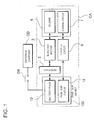
- Fig. 1 is a block diagram showing the vehicle CA that includes the power supply device 100 according to the first embodiment.
- Fig. 2 is a detailed block diagram of the vehicle CA shown in Fig. 1 .
- Fig. 3 is a graph showing SOC time variation in the method for controlling charging/discharging operation of the power supply device 100.
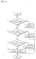
- Fig. 4 is a flow chart of the charging/discharging control method.
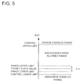
- Fig. 5 is a view schematically showing the relationship of predetermined limits.
- the illustrated power supply device 100 includes a rechargeable battery pack 10, and a power supply controller 12 that controls the power supply device 100.
- the power supply device 100 composes a battery system that provides driving electric power to an electric motor 3 in the vehicle CA.
- the power supply controller 12 serves as a charging/discharging control portion 13, a current detecting portion 14, a battery capacity calculating portion 15, and a power supply side communicating portion 16.
- the charging/discharging control portion 13 controls charging/discharging operation on the battery pack 10.
- the current detecting portion 14 detects charging/discharging currents flowing in the battery pack 10.
- the battery capacity calculating portion 15 estimates the remaining capacity of the battery pack 10 based on the charging/discharging currents detected by the current detecting portion 14.
- the power supply side communicating portion 16 transmits the charging/discharging current limit values based on the remaining capacity of the battery pack 10 estimated by the battery capacity calculating portion 15 to a device side to be provided with electric power (i.e., vehicle main unit).
- the vehicle CA includes an inverter 5, an electric motor 3, an engine 6, an engine controller 7, and a vehicle controller 8.
- the inverter 5 converts DC electric power provided from the power supply device 100 into AC electric power.
- the electric motor 3 is driven by the AC electric power converted by the inverter 5 and by power of the engine 6.
- the engine 6 drives the electric motor 3 and wheels.
- the engine controller 7 controls operation of the engine 6.
- the vehicle controller 8 controls operation of Vehicles CA. (Vehicle Controller 8)
- the vehicles controller 8 controls distribution of gasoline engine output and output from the power supply device 100 based on output requirement.
- the vehicle controller 8 is connected to and can communicate with the power supply controller 12.
- the vehicle controller 8 can receive information including SOC of the battery pack 10 (battery SOC value), available charging/discharging current limit values and the like from the power supply controller 12, and can send output requirement and the like to the power supply controller 12.
- SOC of the battery pack 10 battery SOC value
- available charging/discharging current limit values and the like available charging/discharging current limit values and the like
- the vehicle controller 8 increase output distribution to the power supply device 100. In this case, an EV drive mode is selected in that output distribution to the engine is suppressed.
- the power supply controller 12 allows the amount of a discharging current from the battery pack 10 to exceed the amount of a charging current to the battery pack 10 until the SOC value becomes not more than a predetermined value.
- a mode is selected in that charging/discharging currents are controlled so as to hold the SOC value at a given value.
- the power supply controller 12 notifies the vehicles controller 8 about information that control mode and/or charging/discharging current limit values are changed.
- the vehicles controller 8 switches from the EV drive mode to the HEV drive mode in that the vehicle is driven by both the battery and the engine.
- charging/discharging currents are controlled so that SOC falls within a given range that has its center at the given value. If SOC decreases and reaches a predetermined minimum control value, a discharging operation disabled mode is selected in that the discharging operation is disabled.
- the battery pack 10 can be composed of a plurality of base batteries (battery cells) as rechargeable batteries that are connected to each other in series and/or in parallel.
- Lithium ion batteries, nickel-hydrogen batteries, nickel-cadmium batteries or the like can be suitably used as rechargeable batteries.
- charge storage elements such as electric double layer capacitors can be used as electric power storage elements.
- the battery pack can includes these types of electric power storage elements.
- the battery pack 10 is compose of a number of base batteries connected to each other in series.
- the base batteries are thermally coupled to a temperature sensor(s) so that a temperature signal(s) detected by the temperature sensor(s) is/are sent to the power supply controller 12.
- the temperature sensors can be arranged on all the base batteries. Alternatively, a temperature sensor(s) may be arranged one of or some of the base batteries to representatively detect the battery temperature.
- the battery pack 10 is connected to the inverter 5 via a contactor. A precharging resistor and the contactor are connected to the positive terminal of the battery pack 10.
- the inverter 5 is provided on the vehicle main unit side. However, the inverter may be provided on the power supply device side. The inverter 5 converts DC electric power from the battery pack 10 into AC electric power, and provides the converted electric power to the electric motor 3.
- the battery pack 10 is connected to an externally-connecting switch SW that allows the battery pack 10 to be electrically connected to an external charging device CD.
- the externally-connecting switch SW can be closed (turned ON) so that the battery pack 10 can be charged by the external power source.
- the externally-connecting switch SW can be opened (turned OFF).
- the external charging device CD can be disconnected from the power supply device 100.
- Commercial power, charging station, and the like can be used as the external charging device CD.
- a typical example of the vehicle can be provided by a plug-in hybrid car that can be charged by single-phase commercial power for home use.
- the power supply device 100 thus stores electric power in the battery pack 10, and provides the stored electric power for driving the vehicle.
- the power supply controller 12 shown in Fig. 2 includes a temperature sensor input receiving portion, a voltage sensor input receiving portion, a current sensor input receiving portion as the current detecting portion 14, a battery capacity calculating portion 15, the charging/discharging control portion 13, and a power supply side communicating portion 16 as communication interface.
- the temperature sensor input receiving portion receives output from the temperature sensor thermally coupled to the battery pack 10.
- the voltage sensor input receiving portion receives sensor output from a battery voltage sensor.
- the current sensor input receiving portion receives sensor output from a current sensor.
- the battery capacity calculating portion 15 calculates the battery remaining capacity.
- the charging/discharging control portion 13 controls charging/discharging operation on the battery pack 10.
- the power supply side communicating portion 16 communicates with the vehicle controller 8.
- the battery capacity calculating portion 15 continuously estimates the charged state (SOC: State Of Charge) of the storage batteries.
- SOC can be represented by an absolute value (unit [A-h], etc.) of the charged amount of the battery pack, or a ratio (0 to 100%) of the charged amount relative to the charge capacity of the battery pack.
- the battery capacity calculating portion 15 sequentially calculates SOC based on the integrated value of the charged/discharged amounts of the battery pack.
- the integrated value of the charged/discharged amounts can be obtained by integrating product values of battery voltages and battery currents of the battery pack over time.
- the charging/discharging control portion 13 adjusts the charging/discharging currents flowing in the battery pack 10 to a value not more than the charging/discharging current limit values.
- the charging/discharging control portion 13 compares a predetermined remaining capacity with the remaining capacity calculated by the battery capacity calculating portion 15, and switches between control modes.
- the charging/discharging current limit values are changed depending on the control modes. This control is now described with reference to the graph showing limits and the flowchart of Fig. 4 .
- Step S1 It is first determined in Step S1 whether the remaining capacity (i.e., SOC) is higher than a control upper limit of the battery pack. If SOC is higher than the control upper limit, the procedure goes to Step S1-2, and a charging operation disabled mode is selected in that the charging operation is disabled. In this case, the charging/discharging operation is stopped, and it is determined that battery abnormality occurs. In addition, for example, a warning sign is displayed, or service request is issued.
- SOC remaining capacity
- Step S2 it is determined whether SOC is lower than a control lower limit. If SOC is not higher than the control lower limit, the procedure goes to Step S2-2, and the discharging operation disabled mode is selected in that the discharging operation is disabled, and the procedure ends.
- Step S3 it is determined whether SOC gets beyond a range in proximity to a target state value, more specifically it is determined whether SOC is lower than the upper limit (target state value + ⁇ , hereinafter referred to as range upper limit) of a given range having its center at the target state value (a range of target state value ⁇ ⁇ ). If SOC is higher than the range upper limit, the procedure goes to Step S3-2, an allowance mode is selected that allows a discharging amount to exceed a charging amount in a predetermined period. In this mode, since a discharging amount is allowed to exceed a charging amount, SOC will gradually decrease.
- Step S4 If SOC falls out of the range in proximity to the target state value, the procedure goes to Step S4, and a restriction mode is selected in that the charging/discharging current limit values are reduced so that the remaining capacity is held within the given range having its center at the target state value (from the range upper limit to the range lower limit), and charging/discharging currents are restricted not higher than these limit values.
- Fig. 3 is the graph showing SOC time variation resulting from control mode selection.
- the battery pack is previously charged before the vehicle is driven.
- the battery pack is charged by an external charging device CD with externally-connecting switch SW being ON.
- the battery pack may be charged by an electric generator of the vehicle in case of an emergency.
- charging/discharging operation can be controlled so that the time variation amount of the discharging current in the restriction mode is smaller than the time variation amount of the discharging current in said allowance mode.
- This allowance mode can correspond to the EV drive mode in that the vehicle is mainly driven by the power supply device.
- the EV drive mode is switched to the HEV drive mode so that the discharging current amount is suppressed. Accordingly, the battery pack can be prevented from being over-discharged. Therefore, it is possible to reduce adverse effect on the battery pack.
- the power supply device informs the vehicle side that control modes are switched from one to another or charging/discharging currents are restricted to the charging/discharging current limit values.
- the vehicle side can select a mode that appropriately controls driving operation of the electric motor and the engine.
- the EV drive mode and the HEV drive mode can be appropriately switched from one to another at appropriate timing in so-called plug-in hybrid cars. Therefore, the battery pack can be reliably used for long term.
- the control upper limit can be not less than 80% of the fully-charged capacity of the battery pack, 20 to 60 Ah or the like in consideration of the type, the number, the connection type and the like of used batteries.
- the target state value can be determined in consideration of battery conditions and the like, it is preferable that the target state value be a value not more than 50% of the fully-charged capacity of the battery pack or 2 to 10 Ah.
- drive modes can be selected to keep SOC at about 50%, which is suitable particularly to an HEV drive mode. Therefore, this power supply device is effective for EV/plug-in control.
- the control upper and lower limits, and the target state value can be defined by relative values.
- the predetermined target value can be 5 to 30, preferably 8 to 20 where the control lower limit and the control upper limit are defined as 0 and 100, respectively.
- the given range having its center at the predetermined target value can be defined by ⁇ ( ⁇ can be 5 to 10% of SOC), by a range of 1 to 5 Ah, or the like.
- the aforementioned power supply device can be used as a battery system for vehicles.
- the power supply device can be installed on electric vehicles such as hybrid cars that are driven by both an engine and an electric motor, and electric vehicles that are driven only by a motor.
- the power supply device can be used as a power supply device for these types of vehicles.
- Fig. 6 is a block diagram showing an exemplary hybrid car HV that is driven both by an engine and an electric motor, and includes the power supply device.
- the illustrated vehicle HV with the power supply device includes an engine 96 and an electric motor 93 that drive the vehicle HV, a battery system 100B that supplies electric power to the electric motor 93, and an electric generator 94 that charges batteries of the battery system 100B.
- the battery system 100B is connected to the electric motor 93 and the electric generator 94 via a DC/AC inverter 95.
- the vehicle HV can be driven both by the electric motor 93 and the engine 96 with the batteries of the battery system 100B being charged/discharged.
- the electric motor 93 is energized and drives the vehicle in a poor engine efficiency range, e.g., in acceleration or in a low speed range.
- the electric motor 93 is energized by electric power supplied from the battery system 100B.
- the electric generator 94 can be driven by the engine 96 or by regenerative braking when users brake the vehicle so that the batteries of the battery system 100B are charged.
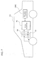
- Fig. 7 shows an exemplary electric vehicle EV that is driven only by an electric motor, and includes the power supply device.
- the illustrated vehicle EV with the power supply device includes an electric motor 93 that drive the vehicle EV, a battery system 100C that supplies electric power to the electric motor 93, and an electric generator 94 that charges batteries of the battery system 100C.
- the electric motor 93 is energized by electric power is supplied from the battery system 100C.
- the electric generator 94 can be driven by vehicle EV regenerative braking so that the batteries of the battery system 100C are charged.
- a power supply device and a method for controlling charging/discharging operation of a power supply device according to the present invention can be suitably applied to charging/discharging control in plug-in hybrid vehicles and hybrid electric vehicles that can switch between the EV drive mode and the HEV drive mode, electric vehicles, and the like.
Landscapes
- Engineering & Computer Science (AREA)
- Mechanical Engineering (AREA)
- Transportation (AREA)
- Chemical & Material Sciences (AREA)
- Power Engineering (AREA)
- Combustion & Propulsion (AREA)
- Sustainable Development (AREA)
- Life Sciences & Earth Sciences (AREA)
- Sustainable Energy (AREA)
- General Chemical & Material Sciences (AREA)
- Electrochemistry (AREA)
- Chemical Kinetics & Catalysis (AREA)
- Manufacturing & Machinery (AREA)
- Automation & Control Theory (AREA)
- Electric Propulsion And Braking For Vehicles (AREA)
- Charge And Discharge Circuits For Batteries Or The Like (AREA)
- Secondary Cells (AREA)
- Battery Mounting, Suspending (AREA)
- Hybrid Electric Vehicles (AREA)
Abstract
Description
- The present invention relates to a power supply device that controls the connection state between a load and a battery pack that is composed of a plurality of rechargeable batteries, and a method for controlling charging/discharging operation of this power supply device. In particular, the present invention relates to a control art that controls the connection state between a battery pack and an inverter in electric vehicles. Examples of such electric vehicles can be provided by battery electric vehicle (BEV), hybrid electric vehicle (HEV), hybrid electric vehicle including fuel cells and rechargeable batteries. Such electric vehicles convert DC electric power into AC electric power by means of an inverter, and provide the converted electric power to an electric motor. The DC electric power is provided from a battery pack as driving power source installed on the electric vehicles.
- In recent years, in consideration of environmental issues, hybrid electric vehicles have been commercially practical that are driven by efficient combination of internal-combustion engine and electric motor: Hybrid electric vehicles include a rechargeable battery pack. The battery pack provides electric power to the electric motor in start, acceleration and the like, and retrieves vehicle kinetic energy as electric power in downhill, breaking and the like.
- A hybrid electric vehicle has been proposed that includes configuration that allows the included battery pack to be charged with electric power provided from external power sources such as commercial power. In this hybrid electric vehicle, in the case where the battery pack is previously charged by external power sources, the vehicle can be driven for a relatively short distance of driving, such as in driving to and from work or for shopping, with its internal-combustion engine being stopped. As a result, it is possible to improve the total fuel consumption efficiency of the vehicle. Such a drive mode is also referred to as an EV (Electric Vehicle) drive mode.
- In order to improve drive performance in this EV drive mode, it is preferable to increase the charging/discharging performance of the battery pack. Since battery packs deteriorate due to over-discharged operation, over-charged operation, and the like, it is important that battery packs are held within a proper range of remaining capacity (also referred to as State Of Charge (SOC), battery charge amount, charge state value and the like, and hereinafter occasionally referred to as "SOC").
- Japanese Patent Laid-Open Publication No.
2008-312381 Fig. 8 , first, a vehicle start running in an EV drive mode (time t1). - In this EV drive mode, when a reset request for a first power storage unit BAT1 (SOC1 reset request) is issued, current control is performed to discharge actively the first power storage unit BAT1. After time t2 when charging by an external power supply becomes allowed, a discharge current of the first power storage unit BAT1 to be reset is kept at a given current value, and a second power storage unit BAT2 not to be reset is charged with a charge current including at least the discharge current of the first power storage unit BAT1. When a distinctive point appears on a battery voltage characteristic of the first power storage unit BAT1 at a subsequent time t3, an estimated value of an SOC of the first power storage unit BAT1 is reset to a predetermined reference value. This control can improve estimation accuracy of SOC of the power storage unit.
- However, estimation accuracy of SOC is limited. For this reason, switching accuracy between BEV and HEV drive modes in accordance only with calculated SOC is limited. In particular, even if an error between the calculated value of SOC and actual SOC is small, errors are accumulated for a long period of use. Accordingly, the accumulated error will be large. If accumulated error of the calculated values of SOC becomes large, precise control will be difficult. Imprecise charging/discharging operation control may affect the battery pack. This increases risk of battery life deterioration.
- The present invention is aimed at solving the problem. It is a main object of the present invention to provide a power supply device and a method for controlling charging/discharging operation of a power supply device capable of changing a charging/discharging current limit values at appropriate timing whereby reducing adverse effect on a battery pack.
- To achieve the above object, a power supply device according to a first aspect of the present invention includes a rechargeable battery pack, a charging/discharging control portion, a current detecting portion, a battery capacity calculating portion. The charging/discharging control portion controls charging/discharging operation on the battery pack. The current detecting portion detects charging/discharging currents flowing in the battery pack. The battery capacity calculating portion estimates the remaining capacity of the battery pack based on the charging/discharging currents detected by the current detecting portion. The charging/discharging control portion selects one of control modes. The charging/discharging operation is controlled based on the selected control mode. When the remaining capacity estimated by the battery capacity calculating portion is higher than a predetermined control upper limit, a charging operation disabled mode is selected in that the charging operation is disabled. When the estimated remaining capacity is lower than a control lower limit specified lower than the control upper limit, a discharging operation disabled mode is selected in that the discharging operation is disabled. When the estimated remaining capacity is higher than an upper limit of a given range having its center at a target state value specified between the control upper and lower limits, an allowance mode is selected in that charging/discharging current limit values are adjusted to current values that allow a discharging amount to exceed a charging amount in a predetermined period. When the estimated remaining capacity is lower than the upper limit of the given range, a restriction mode is selected in that charging/discharging currents are restricted so that the remaining capacity is held within the given range having its center at the target state value. According to this power supply device, since the control modes for controlling charging/discharging currents are thus selected in accordance with the remaining capacity, appropriate operation is achieved. In addition, it is possible to prevent the battery pack from being over-charged/over-discharged, and to provide the battery pack with a long life.
- In a power supply device according to a second aspect of the present invention, the charging/discharging control portion can adjusts the charging/discharging current limit values in the allowance mode to current values that allow the integrated value of the discharging current in the predetermined period to exceed the integrated value of the chagrining current. According to this power supply device, since the discharging current is allowed to be larger than the charging current in the allowance mode, it is possible to effectively use the battery pack within a range in that the battery pack is not over-charged/over-discharged.
- In a power supply device according to a third aspect of the present invention, the charging/discharging control portion can control charging/discharging operation so that the time variation amount of the discharging current is larger than the time variation amount of the charging current in the allowance mode. According to this power supply device, since the discharging current is allowed to be larger than the charging current in the allowance mode, it is possible to effectively use the battery pack within a range in that the battery pack is not over-charged/over-discharged.
- In a power supply device according to a fourth aspect of the present invention, the charging/discharging control portion can control charging/discharging operation so that the time variation amount of the discharging current in the restriction mode is smaller than the time variation amount of the discharging current in the allowance mode. According to this power supply device, since the discharge amount in the restriction mode is suppressed as compared with the allowance mode, it is possible to prevent the battery pack from being over-discharged and to protect the battery pack.
- A power supply device according to a fifth aspect of the present invention can further include a power supply side communicating portion that transmits the charging/discharging current limit values based on the remaining capacity of the battery pack estimated by the battery capacity calculating portion to a device side to be provided with electric power. This power supply device can provide notification of an available current amount depending on the control modes on the power supply device side to the device side to be provided with electric power. For example, after it is detected that the remaining capacity is lower than the upper limit of the given range, the power supply side communicating portion notifies the device side to be provided with electric power that the charging/discharging current limit values are restricted to small values capable of holding the target state value.
- A power supply device according to a sixth aspect of the present invention can further include an externally-connecting switch that can electrically connect the battery pack to an external charging device. According to this power supply device, a battery pack can be charged not only by another battery pack included in the power supply device but also by an external power supply device.
- In a power supply device according to a seventh aspect of the present invention, the power supply device can be a vehicle power supply device. In this case, the allowance mode is an EV drive mode, and the restriction mode is an HEV drive mode. According to this power supply device, the EV drive mode and the HEV drive mode can be switched from one to another at appropriate timing in so-called plug-in hybrid electric cars so as not to adversely affect the battery pack. Therefore, the battery pack can be reliably used for long term.
- In a power supply device according to an eighth aspect of the present invention, the control upper limit can be not less than 80% of the fully-charged capacity of the battery pack.
- In a power supply device according to a ninth aspect of the present invention, the target state value can be not more than 50% of the fully-charged capacity of the battery pack. According to this power supply device, drive modes can be selected to keep SOC at about 50%, which is suitable particularly to an HEV drive mode. Therefore, this power supply device is effective for EV, plug-in control.
- In a power supply device according to a tenth aspect of the present invention, the restriction upper limit can be 20 to 60 Ah.
- In a power supply device according to an eleventh aspect of the present invention, the target state value can be 2 to 10 Ah.
- A method according to a twelfth aspect of the present invention controls charging/discharging operation of a power supply device including a rechargeable battery pack, a charging/discharging control portion that controls charging/discharging operation on the battery pack, a current detecting portion that detects charging/discharging currents flowing in the battery pack, and a battery capacity calculating portion that estimates the remaining capacity of the battery pack based on the charging/discharging currents detected by the current detecting portion. In the method, the remaining capacity estimated by the battery capacity calculating portion is compared with a predetermined control upper limit. The charging operation is disabled when the remaining capacity is higher than the control upper limit. The remaining capacity is compared with a control lower limit determined lower than the control upper limit. The discharging operation is disabled when the remaining capacity is lower than the control lower limit. The remaining capacity is compared with an upper limit of a given range having its center at a target state value specified between the control upper and lower limits. The charging/discharging operation is controlled so that a discharging amount is allowed to exceed a charging amount in a predetermined period when the remaining capacity is higher than the upper limit of the given range. Charging/discharging currents are restricted so that the remaining capacity is held within the given range having its center at the target state value when the remaining capacity is lower than the upper limit of the given range.
- According to this method, since the control modes for controlling charging/discharging currents are thus selected in accordance with the remaining capacity, appropriate operation is achieved. In addition, it is possible to protect the battery pack, and to provide the battery pack with a long life.
- In a method according to a thirteenth aspect of the present invention, the battery pack can be electrically connected to an external charging device to charge the battery pack when operation of a device to be provided with electric power is stopped.
The above and further objects of the present invention as well as the features thereof will become more apparent from the following detailed description to be made in conjunction with the accompanying drawings. -
-
Fig. 1 is a block diagram showing a vehicle that includes a power supply device according to a first embodiment; -
Fig. 2 is a detailed block diagram of the vehicle shown inFig. 1 ; -
Fig. 3 is a graph showing SOC time variation in a method for controlling charging/discharging operation of the power supply device; -
Fig. 4 is a flow chart of the charging/discharging control method; -
Fig. 5 is a view schematically showing the relationship of predetermined limits; -
Fig. 6 is a block diagram showing an exemplary hybrid car that is driven by an engine and an electric motor, and includes the power supply device; -
Fig. 7 is a block diagram showing an exemplary electric vehicle that is driven only by an electric motor, and includes the power supply device; and -
Fig. 8 is a graph showing exemplary known SOC time variation. - The following description will describe embodiments according to the present invention with reference to the drawings. It should be appreciated, however, that the embodiments described below are illustrations of a power supply device and a method for controlling charging/discharging operation of a power supply device to give a concrete form to technical ideas of the invention, and a power supply device and a method for controlling charging/discharging operation of a power supply device of the invention are not specifically limited to description below. Furthermore, it should be appreciated that the members shown in claims attached hereto are not specifically limited to members in the embodiments. Unless otherwise specified, any dimensions, materials, shapes and relative arrangements of the members described in the embodiments are given as an example and not as a limitation. Additionally, the sizes and the positional relationships of the members in each of drawings are occasionally shown larger exaggeratingly for ease of explanation. Members same as or similar to those of this invention are attached with the same designation and the same reference numerals, and their description is omitted. In addition, a plurality of structural elements of the present invention may be configured as a single part that serves the purpose of a plurality of elements, on the other hand, a single structural element may be configured as a plurality of parts that serve the purpose of a single element. Also, the description of some of examples or embodiments may be applied to other examples, embodiments or the like.
- The following description will describe a
power supply device 100 and a charging/discharging control method according to a first embodiment with reference toFigs. 1 to 5 . Thepower supply device 100 according to this embodiment is included in a vehicle (hybrid car) CA.Fig. 1 is a block diagram showing the vehicle CA that includes thepower supply device 100 according to the first embodiment.Fig. 2 is a detailed block diagram of the vehicle CA shown inFig. 1 .Fig. 3 is a graph showing SOC time variation in the method for controlling charging/discharging operation of thepower supply device 100.Fig. 4 is a flow chart of the charging/discharging control method.Fig. 5 is a view schematically showing the relationship of predetermined limits. The illustratedpower supply device 100 includes arechargeable battery pack 10, and apower supply controller 12 that controls thepower supply device 100. Thepower supply device 100 composes a battery system that provides driving electric power to anelectric motor 3 in the vehicle CA. - As shown in
Fig. 2 , thepower supply controller 12 serves as a charging/dischargingcontrol portion 13, a current detectingportion 14, a batterycapacity calculating portion 15, and a power supplyside communicating portion 16. The charging/dischargingcontrol portion 13 controls charging/discharging operation on thebattery pack 10. The current detectingportion 14 detects charging/discharging currents flowing in thebattery pack 10. The batterycapacity calculating portion 15 estimates the remaining capacity of thebattery pack 10 based on the charging/discharging currents detected by the current detectingportion 14. The power supplyside communicating portion 16 transmits the charging/discharging current limit values based on the remaining capacity of thebattery pack 10 estimated by the batterycapacity calculating portion 15 to a device side to be provided with electric power (i.e., vehicle main unit). - As shown in
Fig. 1 , the vehicle CA includes aninverter 5, anelectric motor 3, anengine 6, anengine controller 7, and avehicle controller 8. Theinverter 5 converts DC electric power provided from thepower supply device 100 into AC electric power. Theelectric motor 3 is driven by the AC electric power converted by theinverter 5 and by power of theengine 6. Theengine 6 drives theelectric motor 3 and wheels. Theengine controller 7 controls operation of theengine 6. Thevehicle controller 8 controls operation of Vehicles CA. (Vehicle Controller 8) - The
vehicles controller 8 controls distribution of gasoline engine output and output from thepower supply device 100 based on output requirement. Thevehicle controller 8 is connected to and can communicate with thepower supply controller 12. Thus, thevehicle controller 8 can receive information including SOC of the battery pack 10 (battery SOC value), available charging/discharging current limit values and the like from thepower supply controller 12, and can send output requirement and the like to thepower supply controller 12. When the battery SOC value is high, thevehicle controller 8 increase output distribution to thepower supply device 100. In this case, an EV drive mode is selected in that output distribution to the engine is suppressed. In the EV drive mode, thepower supply controller 12 allows the amount of a discharging current from thebattery pack 10 to exceed the amount of a charging current to thebattery pack 10 until the SOC value becomes not more than a predetermined value. When thepower supply controller 12 detects that the SOC value decreases to the predetermined value, a mode is selected in that charging/discharging currents are controlled so as to hold the SOC value at a given value. In addition, thepower supply controller 12 notifies thevehicles controller 8 about information that control mode and/or charging/discharging current limit values are changed. Correspondingly, thevehicles controller 8 switches from the EV drive mode to the HEV drive mode in that the vehicle is driven by both the battery and the engine. In the HEV drive mode, charging/discharging currents are controlled so that SOC falls within a given range that has its center at the given value. If SOC decreases and reaches a predetermined minimum control value, a discharging operation disabled mode is selected in that the discharging operation is disabled. - The
battery pack 10 can be composed of a plurality of base batteries (battery cells) as rechargeable batteries that are connected to each other in series and/or in parallel. Lithium ion batteries, nickel-hydrogen batteries, nickel-cadmium batteries or the like can be suitably used as rechargeable batteries. Also, in addition to these types of batteries, charge storage elements such as electric double layer capacitors can be used as electric power storage elements. In this specification, the battery pack can includes these types of electric power storage elements. - In the embodiment shown in
Fig. 2 , thebattery pack 10 is compose of a number of base batteries connected to each other in series. The base batteries are thermally coupled to a temperature sensor(s) so that a temperature signal(s) detected by the temperature sensor(s) is/are sent to thepower supply controller 12. The temperature sensors can be arranged on all the base batteries. Alternatively, a temperature sensor(s) may be arranged one of or some of the base batteries to representatively detect the battery temperature. Thebattery pack 10 is connected to theinverter 5 via a contactor. A precharging resistor and the contactor are connected to the positive terminal of thebattery pack 10. In this embodiment, theinverter 5 is provided on the vehicle main unit side. However, the inverter may be provided on the power supply device side. Theinverter 5 converts DC electric power from thebattery pack 10 into AC electric power, and provides the converted electric power to theelectric motor 3. - The
battery pack 10 is connected to an externally-connecting switch SW that allows thebattery pack 10 to be electrically connected to an external charging device CD. When the vehicle CA is at rest, the externally-connecting switch SW can be closed (turned ON) so that thebattery pack 10 can be charged by the external power source. After the battery pack is charged, the externally-connecting switch SW can be opened (turned OFF). After that, the external charging device CD can be disconnected from thepower supply device 100. Commercial power, charging station, and the like can be used as the external charging device CD. A typical example of the vehicle can be provided by a plug-in hybrid car that can be charged by single-phase commercial power for home use. Thepower supply device 100 thus stores electric power in thebattery pack 10, and provides the stored electric power for driving the vehicle. - The
power supply controller 12 shown inFig. 2 includes a temperature sensor input receiving portion, a voltage sensor input receiving portion, a current sensor input receiving portion as the current detectingportion 14, a batterycapacity calculating portion 15, the charging/dischargingcontrol portion 13, and a power supplyside communicating portion 16 as communication interface. The temperature sensor input receiving portion receives output from the temperature sensor thermally coupled to thebattery pack 10. The voltage sensor input receiving portion receives sensor output from a battery voltage sensor. The current sensor input receiving portion receives sensor output from a current sensor. The batterycapacity calculating portion 15 calculates the battery remaining capacity. The charging/dischargingcontrol portion 13 controls charging/discharging operation on thebattery pack 10. The power supplyside communicating portion 16 communicates with thevehicle controller 8. - The battery
capacity calculating portion 15 continuously estimates the charged state (SOC: State Of Charge) of the storage batteries. SOC can be represented by an absolute value (unit [A-h], etc.) of the charged amount of the battery pack, or a ratio (0 to 100%) of the charged amount relative to the charge capacity of the battery pack. In this embodiment, the batterycapacity calculating portion 15 sequentially calculates SOC based on the integrated value of the charged/discharged amounts of the battery pack. The integrated value of the charged/discharged amounts can be obtained by integrating product values of battery voltages and battery currents of the battery pack over time. - The charging/discharging
control portion 13 adjusts the charging/discharging currents flowing in thebattery pack 10 to a value not more than the charging/discharging current limit values. The charging/dischargingcontrol portion 13 compares a predetermined remaining capacity with the remaining capacity calculated by the batterycapacity calculating portion 15, and switches between control modes. The charging/discharging current limit values are changed depending on the control modes. This control is now described with reference to the graph showing limits and the flowchart ofFig. 4 . - It is first determined in Step S1 whether the remaining capacity (i.e., SOC) is higher than a control upper limit of the battery pack. If SOC is higher than the control upper limit, the procedure goes to Step S1-2, and a charging operation disabled mode is selected in that the charging operation is disabled. In this case, the charging/discharging operation is stopped, and it is determined that battery abnormality occurs. In addition, for example, a warning sign is displayed, or service request is issued.
- If SOC is not higher than the control upper limit, the procedure goes to Step S2, it is determined whether SOC is lower than a control lower limit. If SOC is not higher than the control lower limit, the procedure goes to Step S2-2, and the discharging operation disabled mode is selected in that the discharging operation is disabled, and the procedure ends.
- If SOC is higher than the control lower limit, the procedure goes to Step S3, and it is determined whether SOC gets beyond a range in proximity to a target state value, more specifically it is determined whether SOC is lower than the upper limit (target state value + α, hereinafter referred to as range upper limit) of a given range having its center at the target state value (a range of target state value ± α). If SOC is higher than the range upper limit, the procedure goes to Step S3-2, an allowance mode is selected that allows a discharging amount to exceed a charging amount in a predetermined period. In this mode, since a discharging amount is allowed to exceed a charging amount, SOC will gradually decrease.
- If SOC falls out of the range in proximity to the target state value, the procedure goes to Step S4, and a restriction mode is selected in that the charging/discharging current limit values are reduced so that the remaining capacity is held within the given range having its center at the target state value (from the range upper limit to the range lower limit), and charging/discharging currents are restricted not higher than these limit values.
-
Fig. 3 is the graph showing SOC time variation resulting from control mode selection. As shown in this Figure, the battery pack is previously charged before the vehicle is driven. The battery pack is charged by an external charging device CD with externally-connecting switch SW being ON. The battery pack may be charged by an electric generator of the vehicle in case of an emergency. - When SOC reaches the control upper limit so that the battery pack is fully charged, charging operation is disabled. After that, the vehicle is driven. When SOC becomes lower than the control upper limit, the allowance mode is selected. In the allowance mode, a discharging amount is allowed to exceed a charging amount. Specifically, charging/discharging operation is controlled so that the integrated value of discharging amounts is allowed to exceed the integrated value of charging amounts in a predetermined period. Alternatively, charging/discharging operation can be controlled so that the time variation amount of a discharging current is larger than the time variation amount of a charging current in the allowance. Alternatively, charging/discharging operation can be controlled so that the time variation amount of the discharging current in the restriction mode is smaller than the time variation amount of the discharging current in said allowance mode. This allowance mode can correspond to the EV drive mode in that the vehicle is mainly driven by the power supply device.
- After that, when it is detected that SOC becomes low, more specifically, when it is detected that SOC becomes not higher than the range upper limit, the EV drive mode is switched to the HEV drive mode so that the discharging current amount is suppressed. Accordingly, the battery pack can be prevented from being over-discharged. Therefore, it is possible to reduce adverse effect on the battery pack. In addition, the power supply device informs the vehicle side that control modes are switched from one to another or charging/discharging currents are restricted to the charging/discharging current limit values. Correspondingly, the vehicle side can select a mode that appropriately controls driving operation of the electric motor and the engine. As a result, the EV drive mode and the HEV drive mode can be appropriately switched from one to another at appropriate timing in so-called plug-in hybrid cars. Therefore, the battery pack can be reliably used for long term.
- The control upper limit can be not less than 80% of the fully-charged capacity of the battery pack, 20 to 60 Ah or the like in consideration of the type, the number, the connection type and the like of used batteries. Although the target state value can be determined in consideration of battery conditions and the like, it is preferable that the target state value be a value not more than 50% of the fully-charged capacity of the battery pack or 2 to 10 Ah. In this case, drive modes can be selected to keep SOC at about 50%, which is suitable particularly to an HEV drive mode. Therefore, this power supply device is effective for EV/plug-in control. The control upper and lower limits, and the target state value can be defined by relative values. For example, the predetermined target value can be 5 to 30, preferably 8 to 20 where the control lower limit and the control upper limit are defined as 0 and 100, respectively. For example, the given range having its center at the predetermined target value can be defined by ±α (α can be 5 to 10% of SOC), by a range of 1 to 5 Ah, or the like.
- The aforementioned power supply device can be used as a battery system for vehicles. The power supply device can be installed on electric vehicles such as hybrid cars that are driven by both an engine and an electric motor, and electric vehicles that are driven only by a motor. The power supply device can be used as a power supply device for these types of vehicles.
-
Fig. 6 is a block diagram showing an exemplary hybrid car HV that is driven both by an engine and an electric motor, and includes the power supply device. The illustrated vehicle HV with the power supply device includes anengine 96 and anelectric motor 93 that drive the vehicle HV, abattery system 100B that supplies electric power to theelectric motor 93, and anelectric generator 94 that charges batteries of thebattery system 100B. Thebattery system 100B is connected to theelectric motor 93 and theelectric generator 94 via a DC/AC inverter 95. The vehicle HV can be driven both by theelectric motor 93 and theengine 96 with the batteries of thebattery system 100B being charged/discharged. Theelectric motor 93 is energized and drives the vehicle in a poor engine efficiency range, e.g., in acceleration or in a low speed range. Theelectric motor 93 is energized by electric power supplied from thebattery system 100B. Theelectric generator 94 can be driven by theengine 96 or by regenerative braking when users brake the vehicle so that the batteries of thebattery system 100B are charged. -
Fig. 7 shows an exemplary electric vehicle EV that is driven only by an electric motor, and includes the power supply device. The illustrated vehicle EV with the power supply device includes anelectric motor 93 that drive the vehicle EV, abattery system 100C that supplies electric power to theelectric motor 93, and anelectric generator 94 that charges batteries of thebattery system 100C. Theelectric motor 93 is energized by electric power is supplied from thebattery system 100C. Theelectric generator 94 can be driven by vehicle EV regenerative braking so that the batteries of thebattery system 100C are charged. - a power supply device and a method for controlling charging/discharging operation of a power supply device according to the present invention can be suitably applied to charging/discharging control in plug-in hybrid vehicles and hybrid electric vehicles that can switch between the EV drive mode and the HEV drive mode, electric vehicles, and the like.
It should be apparent to those with an ordinary skill in the art that while various preferred embodiments of the invention have been shown and described, it is contemplated that the invention is not limited to the particular embodiments disclosed, which are deemed to be merely illustrative of the inventive concepts and should not be interpreted as limiting the scope of the invention, and which are suitable for all modifications and changes falling within the scope of the invention as defined in the appended claims. - 100 ... Power supply device
- 100B, 100C ... Battery system
- 3 ... Electric motor
- 5 ... Inverter
- 6 ... Engine
- 7 ... Engine controller
- 8 ... Vehicle controller
- 10 ... Battery pack
- 12 ... Power supply controller
- 13 ... Charging/discharging control portion
- 14 ... Current detecting portion
- 15 ... Battery capacity calculating portion
- 16 ... Power supply side communicating portion
- 93 ...Electric motor
- 94 ... Electric generator
- 95 ...DC/AC inverter
- 96 ... Engine
- CA, EV, HV ... Vehicle
- SW ... Externally-connecting switch
- CD ... Charging device
-
- CD: External Charger
- 10: Battery Pack
- 5: Inverter
- 3: Electric Motor
- 6: Engine
- 12: Pwr. Sup. Cntlr
- 8: Vehicle Cntlr
- 7: Engine Cntlr
- Power Supply Device: Pwr. Sup. Device
-
- CD: Charger
- 5: Inverter
- 3: Electric Motor
- 6: Engine
- 8: Vehicle Cntlr
- 7: Engine Cntlr
- Power Supply Controller: Pwr. Sup. Cntlr Current Input Receiver: Cur. Input Receiver Volt Input Receiver: Volt Input Receiver Temperature Input Receiver: Temp. Input Receiver Battery Capacity Calculator: Bat. Cap. Calculator
- Charge/Discharge Controller: Charge/Discharge Cntlr
- Power Supply Communicator: Pwr. Sup. Communicator
- Power Supply Device: Pwr. Sup. Device
-
- Charged Period: Charged Period Allowance Mode: Allowance Mode Restriction Mode: Restriction Mode Time: Time Target State Value: Target State Value
-
- START: START
- S1: Is Remaining Cap. Higher Than Control Upper Limit?
- S2: Is Remaining Cap. Lower Than Control Lower Limit?
- S3: Is Remaining Cap. Higher Than Target Value+α
- S4: Hold Charged Amount In Target Value±α
- S1-2: Disable Charge Op.
- S2-2: Disable Discharge Op.
- S3-2: Allow Excess Discharge Op.
-
- Control Upper Limit: Control Upper Limit
- Range Upper Limit: Range Upper Limit
- Target State Value: Target State Value
- Range Lower Limit: Range Lower Limit
- Control Lower Limit: Control Lower Limit
- Charge Disabled Range: Charge Disabled Range
- Excess Discharge Allowed Range: Excess Discharge Allowed Range
- Discharge Disabled Range: Discharge Disabled Range
-
- 96: Engine 95: DC/
AC Inverter 100B: Battery System -
- 95: DC/AC Inverter
- 100C: Battery System
-
- Externally-Charge Available State: Externally-Charge Available State
- EV Driving: EV Driving
- Reset: Reset
- Externally-Charged: Externally-Charged
Claims (13)
- A power supply device comprising:a rechargeable battery pack (10);a charging/discharging control portion (13) that controls charging/discharging operation on the battery pack (10);a current detecting portion (14) that detects charging/discharging currents flowing in the battery pack (10); anda battery capacity calculating portion (15) that estimates the remaining capacity of the battery pack (10) based on the charging/discharging currents detected by the current detecting portion (14), whereinthe charging/discharging control portion (13) selects one of control modes, the charging/discharging operation being controlled based on the selected control mode, whereinwhen the remaining capacity estimated by the battery capacity calculating portion (15) is higher than a predetermined control upper limit, a charging operation disabled mode is selected in that the charging operation is disabled, andwhen the estimated remaining capacity is lower than a control lower limit specified lower than the control upper limit, a discharging operation disabled mode is selected in that the discharging operation is disabled,
characterized in thatwhen the estimated remaining capacity is higher than an upper limit of a given range having its center at a target state value specified between the control upper and lower limits, an allowance mode is selected in that charging/discharging current limit values are adjusted to current values that allow a discharging amount to exceed a charging amount in a predetermined period, andwhen the estimated remaining capacity is lower than the upper limit of the given range, a restriction mode is selected in that charging/discharging currents are restricted so that the remaining capacity is held within the given range having its center at the target state value. - The power supply device according to claim 1, wherein the charging/discharging control portion (13) adjusts the charging/discharging current limit values in the allowance mode to current values that allow the integrated value of the discharging current in the predetermined period to exceed the integrated value of the chagrining current.
- The power supply device according to claim 1 or 2, wherein the charging/discharging control portion (13) controls charging/discharging operation so that the time variation amount of the discharging current is larger than the time variation amount of the charging current in the allowance mode.
- The power supply device according to any of claims 1 to 3, wherein the charging/discharging control portion (13) controls charging/discharging operation so that the time variation amount of the discharging current in the restriction mode is smaller than the time variation amount of the discharging current in the permission mode.
- The power supply device according to any of claims 1 to 4 further comprising a power supply side communicating portion (16) that transmits the charging/discharging current limit values based on the remaining capacity of the battery pack (10) estimated by the battery capacity calculating portion (15) to a device side to be provided with electric power.
- The power supply device according to any of claims 1 to 5 further comprising an externally-connecting switch (SW) that can electrically connect the battery pack (10) to an external charging device.
- The power supply device according to any of claims 1 to 6, wherein the power supply device is a vehicle power supply device, wherein the allowance mode is an EV drive mode, and the restriction mode is an HEV drive mode.
- The power supply device according to any of claims 1 to 7, wherein the control upper limit is not less than 80% of the fully-charged capacity of the battery pack (10).
- The power supply device according to any of claims 1 to 8, wherein the target state value is not more than 50% of the fully-charged capacity of the battery pack (10).
- The power supply device according to any of claims 1 to 9, wherein the restriction upper limit is 20 to 60 Ah.
- The power supply device according to any of claims 1 to 10, wherein the target state value is 2 to 10 Ah.
- A method for controlling charging/discharging operation of a power supply device, the power supply device including a rechargeable battery pack (10), a charging/discharging control portion (13) that controls charging/discharging operation on the battery pack (10), a current detecting portion (14) that detects charging/discharging currents flowing in the battery pack (10), and a battery capacity calculating portion (15) that estimates the remaining capacity of the battery pack (10) based on the charging/discharging currents detected by the current detecting portion (14), wherein the method comprising the steps of:comparing the remaining capacity estimated by the battery capacity calculating portion (15) with a predetermined control upper limit, and disabling the charging operation when the remaining capacity is higher than the control upper limit;comparing the remaining capacity with a control lower limit determined lower than the control upper limit, and disabling the discharging operation when the remaining capacity is lower than the control lower limit;comparing the remaining capacity with an upper limit of a given range having its center at a target state value specified between the control upper and lower limits, and controlling the charging/discharging operation so that a discharging amount is allowed to exceed a charging amount in a predetermined period when the remaining capacity is higher than the upper limit of the given range; andrestricting charging/discharging currents so that the remaining capacity is held within the given range having its center at the target state value when the remaining capacity is lower than the upper limit of the given range.
- The method for controlling charging/discharging operation of a power supply device according to claim 12 further comprising electrically connecting the battery pack (10) to an external charging device to charge the battery pack (10) when operation of a device to be provided with electric power is stopped.
Applications Claiming Priority (1)
| Application Number | Priority Date | Filing Date | Title |
|---|---|---|---|
| JP2009239522A JP5570782B2 (en) | 2009-10-16 | 2009-10-16 | POWER SUPPLY DEVICE, VEHICLE EQUIPPED WITH THE SAME, AND CHARGING / DISCHARGE CONTROL METHOD FOR POWER SUPPLY DEVICE |
Publications (1)
| Publication Number | Publication Date |
|---|---|
| EP2315301A1 true EP2315301A1 (en) | 2011-04-27 |
Family
ID=43533204
Family Applications (1)
| Application Number | Title | Priority Date | Filing Date |
|---|---|---|---|
| EP10013709A Withdrawn EP2315301A1 (en) | 2009-10-16 | 2010-10-15 | Power supply device and method for controlling charging/discharging operation of power supply device |
Country Status (5)
| Country | Link |
|---|---|
| US (1) | US8436585B2 (en) |
| EP (1) | EP2315301A1 (en) |
| JP (1) | JP5570782B2 (en) |
| KR (1) | KR20110041994A (en) |
| CN (1) | CN102044724A (en) |
Cited By (2)
| Publication number | Priority date | Publication date | Assignee | Title |
|---|---|---|---|---|
| CN103338956A (en) * | 2011-08-30 | 2013-10-02 | 丰田自动车株式会社 | vehicle |
| EP2719053A1 (en) * | 2011-06-07 | 2014-04-16 | VARTA Microbattery GmbH | Emergency system for power failures |
Families Citing this family (46)
| Publication number | Priority date | Publication date | Assignee | Title |
|---|---|---|---|---|
| JP5485392B2 (en) * | 2010-06-30 | 2014-05-07 | 三洋電機株式会社 | Charge / discharge control device |
| US9246345B2 (en) * | 2010-07-28 | 2016-01-26 | Panasonic Intellectual Property Management Co., Ltd. | Power supply system, controller of power supply system, method of operating power supply system, and method of controlling power supply system |
| DE102010038892A1 (en) * | 2010-08-04 | 2012-02-09 | Robert Bosch Gmbh | Method for limiting an inrush current in an electrical network |
| CN103733459B (en) * | 2011-08-23 | 2016-04-06 | 富士通株式会社 | Electric power levelized control device and electric power levelized control method |
| JP5375917B2 (en) * | 2011-09-29 | 2013-12-25 | コベルコクレーン株式会社 | Battery charge / discharge control device for work machine |
| JP5971580B2 (en) * | 2011-11-22 | 2016-08-17 | パナソニックIpマネジメント株式会社 | Discharge system |
| KR101397023B1 (en) * | 2012-03-23 | 2014-05-20 | 삼성에스디아이 주식회사 | Battery pack and method for controlling the same |
| US9365129B2 (en) * | 2012-04-20 | 2016-06-14 | Toyota Jidosha Kabushiki Kaisha | Vehicle having an electric motor and method of controlling a display displaying a cruising distance of the vehicle |
| JP2015172997A (en) * | 2012-07-13 | 2015-10-01 | 三洋電機株式会社 | Battery system, and vehicle and power storage device comprising battery system |
| CN102849066B (en) * | 2012-09-24 | 2015-06-03 | 重庆长鹏实业(集团)有限公司 | Fuel generator controller and control method on basis of oil-electric hybrid electric vehicle |
| US9742218B2 (en) * | 2012-12-04 | 2017-08-22 | Toyota Jidosha Kabushiki Kaisha | Charging control device, charging control method, computer program, and recording medium |
| JP2014241692A (en) * | 2013-06-12 | 2014-12-25 | 住友電気工業株式会社 | Conversion device for storage battery, power supply system, and power supply control method |
| KR101540796B1 (en) * | 2013-07-31 | 2015-07-30 | 김성태 | Apparatus of controllng charging and discharging |
| JP6136784B2 (en) * | 2013-09-04 | 2017-05-31 | トヨタ自動車株式会社 | vehicle |
| KR101555660B1 (en) | 2013-10-14 | 2015-09-25 | 주식회사 엘지화학 | Apparatus and method for maintaining of secondary battery's states of charge |
| WO2015079605A1 (en) * | 2013-11-29 | 2015-06-04 | 三洋電機株式会社 | Charging/discharging control system for electricity storage device |
| JP5925755B2 (en) * | 2013-12-20 | 2016-05-25 | プライムアースEvエナジー株式会社 | Battery module adjustment method and battery module adjustment apparatus |
| JP2015144517A (en) | 2014-01-31 | 2015-08-06 | 株式会社デンソー | Electronic control unit |
| JP6187302B2 (en) * | 2014-02-17 | 2017-08-30 | トヨタ自動車株式会社 | Vehicle control device |
| JP6319053B2 (en) * | 2014-11-06 | 2018-05-09 | トヨタ自動車株式会社 | Vehicle driven by motor, and control method of charge / discharge of secondary battery mounted on vehicle |
| US11444464B1 (en) * | 2016-03-25 | 2022-09-13 | Goal Zero Llc | Portable hybrid generator |
| US10766751B2 (en) * | 2016-04-14 | 2020-09-08 | The Raymond Corporation | Systems and methods for a public standard interface for material handling vehicles |
| JP6404485B2 (en) * | 2016-07-22 | 2018-10-10 | 新電元工業株式会社 | HYBRID VEHICLE POWER SUPPLY DEVICE, HYBRID VEHICLE POWER SUPPLY SYSTEM, AND HYBRID VEHICLE POWER SUPPLY DEVICE CONTROL METHOD |
| WO2018050031A1 (en) * | 2016-09-13 | 2018-03-22 | 南京德朔实业有限公司 | Electric tool system and control method of electric tool system |
| CN109792092B (en) * | 2016-09-13 | 2022-03-18 | 三洋电机株式会社 | Management device and power supply system |
| JP6776904B2 (en) * | 2017-01-13 | 2020-10-28 | 株式会社デンソー | Battery pack and power system |
| CN106864283B (en) * | 2017-02-07 | 2020-02-07 | 上海蔚来汽车有限公司 | Power supply method and service capacity calculation method for electric mobile charging vehicle |
| US11472397B2 (en) | 2018-03-21 | 2022-10-18 | Ford Global Technologies, Llc | Traction-battery control in hybrid powertrain |
| JP7063752B2 (en) * | 2018-07-13 | 2022-05-09 | 日野自動車株式会社 | Charge / discharge control device |
| JP6994440B2 (en) * | 2018-07-26 | 2022-02-04 | ニチコン株式会社 | Charge / discharge device and charge / discharge system |
| EP3626109B1 (en) * | 2018-09-19 | 2021-05-19 | LG Electronics Inc. | Method of controlling dryer and dryer stand |
| JP6617189B1 (en) * | 2018-10-31 | 2019-12-11 | 日本たばこ産業株式会社 | Power supply unit for aerosol inhaler, aerosol inhaler, power control method for aerosol inhaler, and power control program for aerosol inhaler |
| KR102685558B1 (en) * | 2019-01-04 | 2024-07-15 | 주식회사 엘지에너지솔루션 | Battery management method, battery device, and vehicle comprising battery device |
| KR102645052B1 (en) * | 2019-03-05 | 2024-03-08 | 현대자동차주식회사 | Apparatus for controlling driving mode of hybrid vehicle and method thereof |
| JP7116701B2 (en) * | 2019-03-27 | 2022-08-10 | エスペック株式会社 | Charge/discharge test device, control program and charge/discharge test method |
| US11070066B2 (en) * | 2019-04-04 | 2021-07-20 | Caterpillar Inc. | Passive battery cell discharge |
| JP2022123152A (en) * | 2019-06-25 | 2022-08-24 | 三洋電機株式会社 | Power supply device and electric vehicle with power supply device and power storage device |
| CN110400987B (en) * | 2019-07-03 | 2020-09-29 | 华人运通(江苏)技术有限公司 | Battery charging and discharging current limiting method, battery management system and storage medium |
| JP7261983B2 (en) * | 2019-08-02 | 2023-04-21 | パナソニックIpマネジメント株式会社 | POWER SUPPLY DEVICE, POWER SUPPLY SYSTEM, POWER SUPPLY METHOD, PROGRAM |
| KR102681375B1 (en) * | 2019-09-24 | 2024-07-04 | 현대자동차주식회사 | Method for performance recovery of fuel cell stack |
| KR102991090B1 (en) | 2020-08-04 | 2026-07-21 | 삼성전자주식회사 | Electronic device charging battery based on direct charging and operating method thereof |
| WO2022133203A1 (en) | 2020-12-18 | 2022-06-23 | Milwaukee Electric Tool Corporation | Portable power supply |
| KR20220157530A (en) * | 2021-05-21 | 2022-11-29 | 현대자동차주식회사 | Apparatus and method for controlling battery capacity variable |
| JP7705308B2 (en) * | 2021-08-31 | 2025-07-09 | 株式会社Subaru | vehicle |
| CN113716054B (en) * | 2021-09-14 | 2023-06-27 | 上海峰飞航空科技有限公司 | Control method of power system and control method of unmanned aerial vehicle |
| CN117394497B (en) * | 2023-10-31 | 2024-11-19 | 苏州海鹏科技有限公司 | Battery charge and discharge control method based on double-active-bridge energy storage system |
Citations (4)
| Publication number | Priority date | Publication date | Assignee | Title |
|---|---|---|---|---|
| DE19957289A1 (en) * | 1998-11-30 | 2000-05-31 | Sanyo Electric Co | Controlling battery group charging and discharging involves blocking charging and discharging if upper and lower group capacity limit values are reached respectively |
| JP2008312381A (en) | 2007-06-15 | 2008-12-25 | Toyota Motor Corp | Power supply system, vehicle equipped with the same, and charge / discharge control method |
| US20090091299A1 (en) * | 2007-10-04 | 2009-04-09 | Gm Global Technology Operations, Inc. | Dynamically adaptive method for determining the state of charge of a battery |
| DE102009007294A1 (en) * | 2009-02-03 | 2010-08-12 | Lück, Harald | Dynamic battery management |
Family Cites Families (4)
| Publication number | Priority date | Publication date | Assignee | Title |
|---|---|---|---|---|
| KR100333771B1 (en) * | 1998-06-15 | 2002-08-27 | 삼성전자 주식회사 | A method of calibrating rechargeable battery capacity |
| JP2001314040A (en) * | 2000-04-27 | 2001-11-09 | Sanyo Electric Co Ltd | Hybrid car charge / discharge control method |
| JP2004364445A (en) * | 2003-06-06 | 2004-12-24 | Matsushita Electric Ind Co Ltd | Backup battery discharge control device |
| JP5347292B2 (en) * | 2007-08-10 | 2013-11-20 | トヨタ自動車株式会社 | VEHICLE TRAVEL DISPLAY DEVICE, VEHICLE TRAVEL DISPLAY METHOD, AND COMPUTER-READABLE RECORDING MEDIUM CONTAINING PROGRAM FOR CAUSING COMPUTER TO EXECUTE THE TRAVEL DISPLAY METHOD |
-
2009
- 2009-10-16 JP JP2009239522A patent/JP5570782B2/en active Active
-
2010
- 2010-09-29 KR KR1020100094178A patent/KR20110041994A/en not_active Withdrawn
- 2010-10-13 US US12/903,464 patent/US8436585B2/en active Active
- 2010-10-13 CN CN201010510293XA patent/CN102044724A/en active Pending
- 2010-10-15 EP EP10013709A patent/EP2315301A1/en not_active Withdrawn
Patent Citations (4)
| Publication number | Priority date | Publication date | Assignee | Title |
|---|---|---|---|---|
| DE19957289A1 (en) * | 1998-11-30 | 2000-05-31 | Sanyo Electric Co | Controlling battery group charging and discharging involves blocking charging and discharging if upper and lower group capacity limit values are reached respectively |
| JP2008312381A (en) | 2007-06-15 | 2008-12-25 | Toyota Motor Corp | Power supply system, vehicle equipped with the same, and charge / discharge control method |
| US20090091299A1 (en) * | 2007-10-04 | 2009-04-09 | Gm Global Technology Operations, Inc. | Dynamically adaptive method for determining the state of charge of a battery |
| DE102009007294A1 (en) * | 2009-02-03 | 2010-08-12 | Lück, Harald | Dynamic battery management |
Cited By (3)
| Publication number | Priority date | Publication date | Assignee | Title |
|---|---|---|---|---|
| EP2719053A1 (en) * | 2011-06-07 | 2014-04-16 | VARTA Microbattery GmbH | Emergency system for power failures |
| CN103338956A (en) * | 2011-08-30 | 2013-10-02 | 丰田自动车株式会社 | vehicle |
| CN103338956B (en) * | 2011-08-30 | 2016-04-13 | 丰田自动车株式会社 | Vehicle |
Also Published As
| Publication number | Publication date |
|---|---|
| KR20110041994A (en) | 2011-04-22 |
| CN102044724A (en) | 2011-05-04 |
| JP5570782B2 (en) | 2014-08-13 |
| JP2011087428A (en) | 2011-04-28 |
| US8436585B2 (en) | 2013-05-07 |
| US20110089905A1 (en) | 2011-04-21 |
Similar Documents
| Publication | Publication Date | Title |
|---|---|---|
| US8436585B2 (en) | Power supply device | |
| CN108081978B (en) | Battery pre-heating prior to fast charging | |
| JP6445190B2 (en) | Battery control device | |
| US9643498B2 (en) | Method for recharging a pair of vehicle batteries of different nominal voltages, and associated system | |
| US8643332B2 (en) | Battery system and method for detecting internal short circuit in battery system | |
| CN107499136B (en) | Variable wake-up of high voltage charger based on low voltage system parameters | |
| US8532854B2 (en) | Method and apparatus for managing multiple battery packs in a hybrid or electric vehicle | |
| CN106926718B (en) | Method and apparatus for charging a plurality of energy storage devices | |
| US9676281B2 (en) | Hybrid battery system for electric vehicles | |
| EP2343768A2 (en) | Battery system and method for detecting current restriction state in a battery system | |
| EP2670018B1 (en) | Electric vehicle battery system | |
| US20190225092A1 (en) | Energy management system and method for vehicle with high power and high energy battery packs | |
| US9260033B2 (en) | Power supply device and vehicle including the same | |
| US20140176085A1 (en) | Battery controller of vehicle | |
| JP2009195081A (en) | CHARGE CONTROL CIRCUIT, CHARGING DEVICE HAVING THE SAME, AND BATTERY PACK | |
| JP7140852B2 (en) | Hybrid energy storage module system with auxiliary battery | |
| KR101927124B1 (en) | Apparatus for preventing trouble of battery | |
| US20170166078A1 (en) | Battery charge equalization system | |
| US9350186B2 (en) | Battery pack | |
| CN103534128A (en) | Device and method for managing electric braking of a vehicle | |
| JPWO2014068884A1 (en) | Vehicle power supply for regenerative braking | |
| JP5609807B2 (en) | Hysteresis reduction system for battery device | |
| JP6337596B2 (en) | Power supply system and automobile | |
| ES2938792B2 (en) | RECHARGEABLE BATTERY MANAGEMENT SYSTEM FOR BATTERY PACKS FOR ELECTRIC VEHICLES | |
| WO2014171453A1 (en) | Vehicle power supply system |
Legal Events
| Date | Code | Title | Description |
|---|---|---|---|
| PUAI | Public reference made under article 153(3) epc to a published international application that has entered the european phase |
Free format text: ORIGINAL CODE: 0009012 |
|
| AK | Designated contracting states |
Kind code of ref document: A1 Designated state(s): AL AT BE BG CH CY CZ DE DK EE ES FI FR GB GR HR HU IE IS IT LI LT LU LV MC MK MT NL NO PL PT RO RS SE SI SK SM TR |
|
| AX | Request for extension of the european patent |
Extension state: BA ME |
|
| 17P | Request for examination filed |
Effective date: 20111026 |
|
| 17Q | First examination report despatched |
Effective date: 20120424 |
|
| GRAJ | Information related to disapproval of communication of intention to grant by the applicant or resumption of examination proceedings by the epo deleted |
Free format text: ORIGINAL CODE: EPIDOSDIGR1 |
|
| GRAP | Despatch of communication of intention to grant a patent |
Free format text: ORIGINAL CODE: EPIDOSNIGR1 |
|
| INTG | Intention to grant announced |
Effective date: 20130731 |
|
| RAP1 | Party data changed (applicant data changed or rights of an application transferred) |
Owner name: SANYO ELECTRIC CO., LTD. |
|
| RIN1 | Information on inventor provided before grant (corrected) |
Inventor name: YANO, JUNYA |
|
| STAA | Information on the status of an ep patent application or granted ep patent |
Free format text: STATUS: THE APPLICATION IS DEEMED TO BE WITHDRAWN |
|
| 18D | Application deemed to be withdrawn |
Effective date: 20131211 |