EP2315285A1 - Apparatus for regulating the temperature of a light emitting diode - Google Patents
Apparatus for regulating the temperature of a light emitting diode Download PDFInfo
- Publication number
- EP2315285A1 EP2315285A1 EP09173748A EP09173748A EP2315285A1 EP 2315285 A1 EP2315285 A1 EP 2315285A1 EP 09173748 A EP09173748 A EP 09173748A EP 09173748 A EP09173748 A EP 09173748A EP 2315285 A1 EP2315285 A1 EP 2315285A1
- Authority
- EP
- European Patent Office
- Prior art keywords
- led
- temperature
- heat sink
- change
- mount
- Prior art date
- Legal status (The legal status is an assumption and is not a legal conclusion. Google has not performed a legal analysis and makes no representation as to the accuracy of the status listed.)
- Granted
Links
Images
Classifications
-
- H—ELECTRICITY
- H10—SEMICONDUCTOR DEVICES; ELECTRIC SOLID-STATE DEVICES NOT OTHERWISE PROVIDED FOR
- H10H—INORGANIC LIGHT-EMITTING SEMICONDUCTOR DEVICES HAVING POTENTIAL BARRIERS
- H10H20/00—Individual inorganic light-emitting semiconductor devices having potential barriers, e.g. light-emitting diodes [LED]
- H10H20/80—Constructional details
- H10H20/85—Packages
- H10H20/858—Means for heat extraction or cooling
- H10H20/8582—Means for heat extraction or cooling characterised by their shape
-
- H—ELECTRICITY
- H10—SEMICONDUCTOR DEVICES; ELECTRIC SOLID-STATE DEVICES NOT OTHERWISE PROVIDED FOR
- H10H—INORGANIC LIGHT-EMITTING SEMICONDUCTOR DEVICES HAVING POTENTIAL BARRIERS
- H10H20/00—Individual inorganic light-emitting semiconductor devices having potential barriers, e.g. light-emitting diodes [LED]
- H10H20/80—Constructional details
- H10H20/85—Packages
- H10H20/8506—Containers
-
- F—MECHANICAL ENGINEERING; LIGHTING; HEATING; WEAPONS; BLASTING
- F21—LIGHTING
- F21V—FUNCTIONAL FEATURES OR DETAILS OF LIGHTING DEVICES OR SYSTEMS THEREOF; STRUCTURAL COMBINATIONS OF LIGHTING DEVICES WITH OTHER ARTICLES, NOT OTHERWISE PROVIDED FOR
- F21V29/00—Protecting lighting devices from thermal damage; Cooling or heating arrangements specially adapted for lighting devices or systems
- F21V29/50—Cooling arrangements
- F21V29/70—Cooling arrangements characterised by passive heat-dissipating elements, e.g. heat-sinks
-
- F—MECHANICAL ENGINEERING; LIGHTING; HEATING; WEAPONS; BLASTING
- F21—LIGHTING
- F21Y—INDEXING SCHEME ASSOCIATED WITH SUBCLASSES F21K, F21L, F21S and F21V, RELATING TO THE FORM OR THE KIND OF THE LIGHT SOURCES OR OF THE COLOUR OF THE LIGHT EMITTED
- F21Y2115/00—Light-generating elements of semiconductor light sources
- F21Y2115/10—Light-emitting diodes [LED]
Definitions
- This invention relates to semiconductor devices such as light emitting diodes.
- this invention relates to an apparatus for regulating the temperature of a light emitting diode.
- the emission spectrum (in terms of both intensity and peak wavelength) of an LED is temperature dependent. In particular, it is the junction temperature of the LED that influences the emission spectrum. To achieve a stable light output from an LED, it is therefore necessary to regulate the temperature of the LED.
- the junction temperature in the LED is measured directly or indirectly via a temperature sensor and a model to derive the junction temperature, and the LED is then operated (by adjusting the amplitude, frequency and/or duty cycle of the current passing through the LED) to react to any changes in LED temperature.
- Arrangements of this kind are complex, and require the provision of a control loop including at least a variable current supply and means for measuring the LED temperature.
- an apparatus for regulating the temperature of a light emitting diode includes a heat sink, an LED mount, and an LED mounted on the LED mount.
- the LED mount is configured to change shape in response to a change in temperature. The change in shape alters the position of the LED relative to the heat sink, for adjusting heat transfer between the LED and the heat sink.
- the mount on which an LED is mounted changes shape (e.g. becomes larger, smaller, longer, shorter etc.) in response to a change in temperature, in order to change the position of the LED in relation to a heat sink.
- the changes in position of the LED relative to the heat sink can be used to modulate heat transfer between the heat sink and the LED.
- the change in shape of the mount can alter the position of the LED relative to the heat sink, to bring the LED into physical contact with the heat sink, in response to an increase in temperature.
- the LED can be put into contact with the heat sink, thereby increasing heat flow from the LED to the heat sink, thereby providing additional cooling power to lower the LED temperature.
- the change in shape of the mount can also alter the position of the LED relative to the heat sink, to break physical contact between the LED and the heat sink in response to a decrease in temperature. The decrease in cooling power caused by the lack of physical contact between the LED and the heat sink can thereby cause an increase in temperature in the LED.
- the LED mount is configured to alter the position of the LED relative to the heat sink, to maintain the temperature of the LED between a maximum temperature and a minimum temperature.
- physical contact between the LED and the heat sink can be formed as the temperature of the LED approaches or becomes substantially equal to the maximum temperature.
- physical contact between the LED and the heat sink can be broken as the temperature of the LED approaches or becomes substantially equal to said minimum temperature.
- LED mounts that can change shape in response to a change in temperature are described herein.
- at least a portion of the LED mount is configured to undergo thermal expansion and/or thermal contraction in response to a change in temperature, for changing the shape of the LED mount.
- the LED mount comprises a laminated portion with at least two layers having different coefficients of thermal expansion. The at least two layers can be arranged to expand and contract at different rates in response to a change in temperature, thereby to cause the LED mount to change shape.
- the layers may comprise metallic strips having different coefficients of thermal expansion.
- the LED mount comprises at least one elongate finger on which said LED is mounted.
- the LED may be mounted substantially at one end of the finger.
- the finger can be configured to bend in response to a change in temperature, thereby to deflect the LED toward or away from the heat sink in response to said change in temperature.
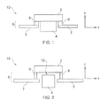
- FIGs 1 and 2 schematically illustrate a first embodiment of the invention.
- an LED 2 mounted on an LED mount 6, and a heat sink 4.
- the LED mount 6 includes a first portion 7 and a second portion 8.
- the first portion 7 of the LED mount 6 is generally fixed in position, and may, for example, comprise a part of a printed circuit board (PCB), or another part of the housing of the device into which the LED 2 is incorporated.
- PCB printed circuit board
- the second portion 8 of the LED mount 6 is configured to change shape in response to a change in temperature.
- This change in shape may, for example, arise from thermal expansion/contraction within the second portion 8.
- the change in temperature in the second portion 8 arises from the dissipation of heat from the LED 2 to the second portion 8. Due to thermal conduction between the LED 2 and the second portion 8, the temperature of the second portion 8 will tend to track the temperature of the LED 2.
- the second portion is shown schematically Figures 1 and 2 , for the purpose is illustrating how a change in shape in the second portion 8 can be used to regulate the temperature of the LED 2. Examples of particular structures that can be employed to implement the second portion 8 are described hereinafter.
- a change in shape of the second portion 8 changes the position of the LED 2 with respect to the heat sink 4. More particularly, movement of the LED 2 relative to the heat sink 4 can bring the LED 2 into contact with the heat sink 4 (as shown in Figure 1 ). Movement of the LED 2 relative to the heat sink can also to break physical contact between the LED 2 and the heat sink 4 (as shown in Figure 2 ). When physical contact between the LED 2 and the heat sink 4 is broken as shown in Figure 2 , a gap 12 is opened there between.
- the position of the LED 2 relative to the heat sink 4 can be altered (by a change in shape of the LED mount 6) for adjusting heat transfer between the LED 2 and the heat sink 4.
- the second portion 8 of the LED mount 6 expands in the z direction to break physical contact between the LED 2 and the heat sink 4, reaching the configuration shown in Figure 2 .
- the change in shape of the second portion 8 is prompted by decrease in temperature in the second portion 8, owing to reduced heat dissipation from the relatively cool LED 2.
- the gap 12 between the LED 2 and the heat sink 4 subsequently reduces thermal flow between the LED 2 and the heat sink 4, whereby the temperature of the LED 2 will tend to increase, in turn increasing heat dissipation to the LED mount 6, increasing the temperature of the second portion 8.
- the second portion 8 contracts in the z direction, thereby to reach the configuration shown in Figure 1 .
- the renewed contact between the LED 2 and the heat sink 4 increases thermal flow from the LED 2 to the heat sink 4 and thereby tends to decrease the temperature of the LED 2.
- the cycle described above may repeat itself during normal operation of the LED 2, thereby to regulate the temperature of the LED 2.
- the regulation of the temperature may be carried out within predefined upper and lower temperature limits, and the second portion 8 of the LED mount 6 can be configured to provide appropriate movement of the LED 2 relative to the heat sink 4 to ensure that the temperature of the LED 2 does not step outside those predetermined limits.
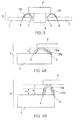
- a second embodiment of the invention is schematically illustrated in Figures 3 and 4 .
- the second embodiment includes an LED 2, and a heat sink 4.
- the LED 2 is mounted on an LED mount 6 which includes a first portion 7 and a second portion 18.
- the second portion 18 of the LED mount 6 is configured to change shape in response to a change in temperature, for altering the position of the LED 2 relative to the heat sink 4, for adjusting heat transferred between the LED 2 and the heat sink 4.
- the second portions 18 of the LED mount 6 are curved in shape, and in this example take the form of one or more elongate fingers mounted on the first portion 7.
- the finger(s) can be provided at regular intervals around the periphery of the LED 2.
- a first end (labelled A) of each elongate finger is fixed to the first portion 7, while a second end of each elongate finger (labelled B) is free to move, as described in more detail below.
- the second portions 18 are shown in more detail in Figures 4a and 4b .
- the second portion 18 is shown to be laminated in structure, having a first layer 18a and a second layer 18b.
- the first layer 18a is located above the second layer 18b.
- the first layer 18a and the second layer 18b have different coefficients of thermal expansion. In particular, the linear coefficient of thermal expansion of the first layer 18a is less than that of the second layer 18b.
- the height of the LED relative to, for example, the first portion 7 of the LED mount 6 is h 2 (see Figure 4b ).
- the LED 2 is typically not in contact with the heat sink 4 (this configuration is therefore analogous with the configuration shown in Figure 2 ). Accordingly, in this configuration, heat flow between the LED 2 and the heat sink 4 is restricted, whereby the temperature of the LED 2 will tend to increase.
- the temperature of the second portion 18 of the LED mount 6 will also tend to increase, by thermal conduction between the LED 2 and the second portion 18, upon which the LED 2 is mounted.
- the first layer 18a and the second layer 18b will tend to expand.
- this will tend to cause a distortion (a change in shape) in the second portion 18.
- the second layer 18b will tend to expand to a greater extent than the first layer 18a. This will tend to reduce the curvature of the second portion 18, so that it adopts a straighter configuration, as shown in Figure 4A .
- the change in shape causes the free end B of each elongate finger to move along the surface of the first portion 7.
- the change in shape also reduces the vertical height of the second portion 18 of the LED mount 6 to h 1 as illustrated in Figures 4a and 4b . Accordingly, in this example, the second portion expands in the horizontal dimension and contracts in the vertical dimension, in response to an increase in temperature.
- This reduction in vertical height of the second portion 18 can cause the LED 2 to resume physical contact with the heat sink 4, thereby enhancing the cooling power of the heat sink or the LED 2 as described above.
- the second portion 18 upon which the LED 2 is mounted will also tend to cool owing to a lack of heat transfer from the LED 2. Due to this cooling, the first layer 18a and the second layer 18b of the second portion 18 will tend to contract thermally, thereby to resume the configuration shown in Figure 4b .
- cyclic thermal expansion/contraction of the first layer 18a and the second layer 18b of the second portion 18 of the LED mount 6 can cause the LED 2 to alter position relative to the heat sink, for adjusting heat transfer between the LED 2 and the heat sink 4.
- a third embodiment of the invention is schematically illustrated in Figures 5 and 6 .
- the LED 2 is mounted on an LED mount 6.
- the LED mount 6 includes a laminated portion 28 comprising a first layer 28a and a second layer 28b.
- the laminated portion 28 can take the form of one or more elongate fingers, with the LED 2 attached to the tip of each of the fingers.
- the other end of each of the fingers can be mounted on for example, a PCB or some other structure.
- two fingers are provided. In other examples, more fingers (or even just a single finger) may be provided.
- the laminated portion 28 is configured to change shape in response to a change in temperature, in order to alter the position of the LED 2 relative to the heat sink 4. More particularly, in this example, the second layer 28b has a linear coefficient of thermal expansion that is greater than that of the first layer 28a. As is illustrated in Figures 5 and 6 , as the laminated portion 28 increases in temperature, it will therefore tend to straighten out. Conversely, at lower temperatures, the curvature of the laminated portion 28 is increased.
- an increase in temperature in the LED 2 causing a corresponding increase in temperature of the laminated portion 28 can in turn cause the laminated portion 28 to adopt a straighter configuration.
- the physical contact between the LED 2 and the heat sink 4 increases the cooling power provided by the heat sink 4 for the LED 2, and the LED 2 will consequently tend to cool.
- the change in curvature of the laminated portion 28 alters the position of the LED 2 relative to the heat sink 4, such that physical contact is broken, and a gap 12 opens up between the LED 2 and the heat sink 4 ( Figure 6 ). This reduces the cooling power provided by the heat sink 4, whereby the temperature of the LED 2 will tend to increase.
- the cycle described above can, as hereinbefore described, be used to regulate the temperature of the LED 2 between predetermined limits.
- laminated portions such as the layers 18a and 18b and the layers 28a and 28b.
- These laminated portions may take the form of a bi-metallic strip.
- these bimetallic strips may be constructed of two separate metallic materials, with a first material being used for one of the layers and a second material being used for another of the layers.
- the laminated portions are not restricted to comprising only two layers. It is envisaged that more than two layers may also be employed, with a similar effect. Typical materials that may be used in the strips include Iron, Nickel and Copper.
- the change in shape of the LED mount 6 (or at least a portion thereof) can be preconfigured to regulate the temperature of the LED 2 between predetermined temperature limits. This is discussed in more detail below with respect to Figure 7 .
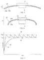
- Figure 7 illustrates the temperature regulation of an LED in accordance with an embodiment of the invention.
- the graph of Figure 7 plots the temperature of the LED as a function of time.
- the line 32 illustrates the temperature behaviour of an LED mounted on an LED mount in accordance with an embodiment of this invention, for regulation between a minimum desired temperature T MIN and a maximum temperature T MAX .
- the temperatures T MIN and T MAX can be chosen to optimise the temperature of the LED for a given output, in terms of intensity and/or wavelength.
- the LED is initially not in contact with the heat sink. Accordingly, and as shown by the line 32, initially, the temperature of the LED ramps up at an increased rate until it reaches temperature T MAX . At this point, the increased temperature causes a change in shape of the LED mount, thereby to bring the LED into contact with the heat sink. As illustrated by the line 32, this leads to a drop in temperature in the LED.
- the temperature continues to drop until the temperature T MIN is reached, whereby a change in shape in the LED mount again alters the position of the LED relative to the heat sink, thereby to break physical contact between the LED 2 and the heat sink 4.
- the temperature of the LED 2 begins to ramp up again.
- the above described cycle can repeat itself indefinitely, with the LED 2 being brought into physical contact and out of physical contact with the heat sink 4, thereby to regulate the temperature of the LED 2 between the predetermined temperatures T MIN and T MAX .
- the change in shape of the LED mount may not be abrupt, and therefore may not take place exactly at the point 34 where the temperature reaches T MAX or at the point 36 where the temperature reaches T MIN .
- the change in shape may be gradual, continuously to alter the relative position of the LED 2 and the heat sink 4.
- the making and/or breaking of physical contact may not take place in an abrupt manner, but may also take place in a continuous fashion.
- the contact surface area of the LED 2 and the heat sink 4 can alter continuously in accordance with a relative change in position between the LED 2 and the heat sink 4.
- the change in contact surface area between the LED 2 and the heat sink 4 would also lead to a corresponding change in cooling power provided by the heat sink 4 for the LED 2, which would again have a regulatory effect on temperature of the LED 2.
- Such an embodiment may or may not also involve actual breaking of contact between the LED 2 and the heat sink 4.
- the curve shown in Figure 7 would not comprise the sharp points 34 and 36, and instead of a saw-tooth line shape, a more rounded, undulating line shape would be observed.
- the shape and configuration as well as the materials used in the LED mount.
- the length, thickness and/or curvature of the respective layers can be selected. Materials having known coefficients of thermal expansion can also be selected as appropriate, in accordance with the desired amount of distortion that is required.
- the apparatus includes a heat sink, an LED mount, and an LED mounted on the LED mount.
- the LED mount is configured to change shape in response to a change in temperature. The change in shape alters the position of the LED relative to the heat sink, for adjusting heat transfer between the LED and the heat sink.
- the LED mount may include a laminated portion such as a bi-metallic strip.
Landscapes
- Arrangement Of Elements, Cooling, Sealing, Or The Like Of Lighting Devices (AREA)
- Led Device Packages (AREA)
- Cooling Or The Like Of Semiconductors Or Solid State Devices (AREA)
Abstract

Description
- This invention relates to semiconductor devices such as light emitting diodes. In particular, this invention relates to an apparatus for regulating the temperature of a light emitting diode.
- The emission spectrum (in terms of both intensity and peak wavelength) of an LED is temperature dependent. In particular, it is the junction temperature of the LED that influences the emission spectrum. To achieve a stable light output from an LED, it is therefore necessary to regulate the temperature of the LED.
- Traditionally, the junction temperature in the LED is measured directly or indirectly via a temperature sensor and a model to derive the junction temperature, and the LED is then operated (by adjusting the amplitude, frequency and/or duty cycle of the current passing through the LED) to react to any changes in LED temperature. Arrangements of this kind are complex, and require the provision of a control loop including at least a variable current supply and means for measuring the LED temperature.
- Aspects of the invention are set out in the accompanying independent and dependent claims. Combinations of features from the dependent claims may be combined with features of the independent claims as appropriate and not merely as explicitly set out in the claims.
- According to an aspect of the invention, there is provided an apparatus for regulating the temperature of a light emitting diode (LED). The apparatus includes a heat sink, an LED mount, and an LED mounted on the LED mount. The LED mount is configured to change shape in response to a change in temperature. The change in shape alters the position of the LED relative to the heat sink, for adjusting heat transfer between the LED and the heat sink.
- This invention provides a solution to the problem of LED temperature regulation, which does not require a complex control loop of the kind described above. In accordance with the invention, the mount on which an LED is mounted changes shape (e.g. becomes larger, smaller, longer, shorter etc.) in response to a change in temperature, in order to change the position of the LED in relation to a heat sink. In particular, the changes in position of the LED relative to the heat sink can be used to modulate heat transfer between the heat sink and the LED.
- In one example, the change in shape of the mount can alter the position of the LED relative to the heat sink, to bring the LED into physical contact with the heat sink, in response to an increase in temperature. Thus, as the temperature increases, the LED can be put into contact with the heat sink, thereby increasing heat flow from the LED to the heat sink, thereby providing additional cooling power to lower the LED temperature. Conversely, the change in shape of the mount can also alter the position of the LED relative to the heat sink, to break physical contact between the LED and the heat sink in response to a decrease in temperature. The decrease in cooling power caused by the lack of physical contact between the LED and the heat sink can thereby cause an increase in temperature in the LED.
- In one embodiment, the LED mount is configured to alter the position of the LED relative to the heat sink, to maintain the temperature of the LED between a maximum temperature and a minimum temperature. By way of example only, physical contact between the LED and the heat sink can be formed as the temperature of the LED approaches or becomes substantially equal to the maximum temperature. Conversely, physical contact between the LED and the heat sink can be broken as the temperature of the LED approaches or becomes substantially equal to said minimum temperature.
- Numerous examples of LED mounts that can change shape in response to a change in temperature are described herein. In one such example, at least a portion of the LED mount is configured to undergo thermal expansion and/or thermal contraction in response to a change in temperature, for changing the shape of the LED mount. In another example, the LED mount comprises a laminated portion with at least two layers having different coefficients of thermal expansion. The at least two layers can be arranged to expand and contract at different rates in response to a change in temperature, thereby to cause the LED mount to change shape. The layers may comprise metallic strips having different coefficients of thermal expansion.
- In a further example, the LED mount comprises at least one elongate finger on which said LED is mounted. The LED may be mounted substantially at one end of the finger. The finger can be configured to bend in response to a change in temperature, thereby to deflect the LED toward or away from the heat sink in response to said change in temperature.
- Embodiments of the present invention will be described hereinafter, by way of example only, with reference to the accompanying drawings in which like reference signs relate to like elements and in which:
-
Figure 1 shows an example of an apparatus comprising an LED mount, an LED, and a heat sink, in accordance with an embodiment of the invention; -
Figure 2 shows the example apparatus ofFigure 1 , following a change of shape of the LED mount; -
Figure 3 shows an example of an apparatus comprising an LED mount, an LED, and a heat sink, in accordance with an embodiment of the invention; -
Figures 4A and 4B show the LED mount of the apparatus ofFigure 3 in more detail; -
Figure 5 shows an example of an apparatus comprising an LED mount, an LED, and a heat sink, in accordance with an embodiment of the invention; -
Figure 6 shows the example apparatus ofFigure 5 , following a change of shape of the LED mount; and -
Figure 7 shows a graph of temperature as a function of time, illustrating temperature regulation of an LED in accordance with an embodiment of the invention. - Embodiments of the present invention are described in the following with reference to the accompanying drawings.
-
Figures 1 and 2 schematically illustrate a first embodiment of the invention. In accordance with this embodiment, there is provided anLED 2 mounted on anLED mount 6, and aheat sink 4. As shown inFigures 1 and 2 , theLED mount 6 includes afirst portion 7 and a second portion 8. Thefirst portion 7 of theLED mount 6 is generally fixed in position, and may, for example, comprise a part of a printed circuit board (PCB), or another part of the housing of the device into which theLED 2 is incorporated. - The second portion 8 of the
LED mount 6 is configured to change shape in response to a change in temperature. This change in shape may, for example, arise from thermal expansion/contraction within the second portion 8. Generally, the change in temperature in the second portion 8 arises from the dissipation of heat from theLED 2 to the second portion 8. Due to thermal conduction between theLED 2 and the second portion 8, the temperature of the second portion 8 will tend to track the temperature of theLED 2. The second portion is shown schematicallyFigures 1 and 2 , for the purpose is illustrating how a change in shape in the second portion 8 can be used to regulate the temperature of theLED 2. Examples of particular structures that can be employed to implement the second portion 8 are described hereinafter. - As is illustrated in
Figures 1 and 2 , since theLED 2 is attached to the second portion 8, a change in shape of the second portion 8 changes the position of theLED 2 with respect to theheat sink 4. More particularly, movement of theLED 2 relative to theheat sink 4 can bring theLED 2 into contact with the heat sink 4 (as shown inFigure 1 ). Movement of theLED 2 relative to the heat sink can also to break physical contact between theLED 2 and the heat sink 4 (as shown inFigure 2 ). When physical contact between theLED 2 and theheat sink 4 is broken as shown inFigure 2 , agap 12 is opened there between. - While the
LED 2 and theheat sink 4 are in physical contact, a good thermal contact exists between theLED 2 and theheat sink 4. Under these conditions, heat may freely flow from theLED 2 to theheat sink 4, whereby theheat sink 4 is able to provide effect cooling power for the LED 2.Conversely, while thegap 12 between theLED 2 andheat sink 4 is exists, there is only a weak thermal contact between theLED 2 and the heat sink 4s. Although a small quantity of heat may still nevertheless bridge thegap 12 between theLED 2 and theheat sink 4, the cooling power provided by theheat sink 4 in this configuration is minimal. Since theLED 2 continually produces heat during operation, when thegap 12 is present the temperature of the LED 2 (and consequently the second portion 8) will tend to increase. However, when theLED 2 is in contact with theheat sink 4, the cooling power of theheat sink 4 will tend to lead to a drop in temperature in the LED 2 (and consequently in the second portion 8 also). - According to the invention therefore, the position of the
LED 2 relative to theheat sink 4 can be altered (by a change in shape of the LED mount 6) for adjusting heat transfer between theLED 2 and theheat sink 4. In particular, in this embodiment, as the temperature of theLED 2 decreases, the second portion 8 of theLED mount 6 expands in the z direction to break physical contact between theLED 2 and theheat sink 4, reaching the configuration shown inFigure 2 . As described above, the change in shape of the second portion 8 is prompted by decrease in temperature in the second portion 8, owing to reduced heat dissipation from the relativelycool LED 2. Thegap 12 between theLED 2 and theheat sink 4 subsequently reduces thermal flow between theLED 2 and theheat sink 4, whereby the temperature of theLED 2 will tend to increase, in turn increasing heat dissipation to theLED mount 6, increasing the temperature of the second portion 8. In reaction to this increase in temperature, the second portion 8 contracts in the z direction, thereby to reach the configuration shown inFigure 1 . The renewed contact between theLED 2 and theheat sink 4 increases thermal flow from theLED 2 to theheat sink 4 and thereby tends to decrease the temperature of theLED 2. - The cycle described above may repeat itself during normal operation of the
LED 2, thereby to regulate the temperature of theLED 2. As described hereinafter, the regulation of the temperature may be carried out within predefined upper and lower temperature limits, and the second portion 8 of theLED mount 6 can be configured to provide appropriate movement of theLED 2 relative to theheat sink 4 to ensure that the temperature of theLED 2 does not step outside those predetermined limits. - A second embodiment of the invention is schematically illustrated in
Figures 3 and 4 . In common with the embodiment described above in relation toFigures 1 and 2 , the second embodiment includes anLED 2, and aheat sink 4. TheLED 2 is mounted on anLED mount 6 which includes afirst portion 7 and asecond portion 18. As described above in relation to the first embodiment, thesecond portion 18 of theLED mount 6 is configured to change shape in response to a change in temperature, for altering the position of theLED 2 relative to theheat sink 4, for adjusting heat transferred between theLED 2 and theheat sink 4. - As shown in
Figure 3 , thesecond portions 18 of theLED mount 6 are curved in shape, and in this example take the form of one or more elongate fingers mounted on thefirst portion 7. In one embodiment, the finger(s) can be provided at regular intervals around the periphery of theLED 2. A first end (labelled A) of each elongate finger is fixed to thefirst portion 7, while a second end of each elongate finger (labelled B) is free to move, as described in more detail below. - The
second portions 18 are shown in more detail inFigures 4a and 4b . In particular, thesecond portion 18 is shown to be laminated in structure, having afirst layer 18a and asecond layer 18b. Thefirst layer 18a is located above thesecond layer 18b. Thefirst layer 18a and thesecond layer 18b have different coefficients of thermal expansion. In particular, the linear coefficient of thermal expansion of thefirst layer 18a is less than that of thesecond layer 18b. - Starting with
Figure 4b , the operation of thelayers second portion 18 of theLED mount 6 will now be described. In the configuration shown inFigure 4b , the height of the LED relative to, for example, thefirst portion 7 of theLED mount 6 is h2 (seeFigure 4b ). In this configuration, theLED 2 is typically not in contact with the heat sink 4 (this configuration is therefore analogous with the configuration shown inFigure 2 ). Accordingly, in this configuration, heat flow between theLED 2 and theheat sink 4 is restricted, whereby the temperature of theLED 2 will tend to increase. As the temperature of theLED 2 increases, the temperature of thesecond portion 18 of theLED mount 6 will also tend to increase, by thermal conduction between theLED 2 and thesecond portion 18, upon which theLED 2 is mounted. In response to this change in temperature of thesecond portion 18, thefirst layer 18a and thesecond layer 18b will tend to expand. However, because thefirst layer 18a and thesecond layer 18b have different coefficients of thermal expansion, this will tend to cause a distortion (a change in shape) in thesecond portion 18. In particular, thesecond layer 18b will tend to expand to a greater extent than thefirst layer 18a. This will tend to reduce the curvature of thesecond portion 18, so that it adopts a straighter configuration, as shown inFigure 4A . Note that in this example, the change in shape causes the free end B of each elongate finger to move along the surface of thefirst portion 7. The change in shape also reduces the vertical height of thesecond portion 18 of theLED mount 6 to h1 as illustrated inFigures 4a and 4b . Accordingly, in this example, the second portion expands in the horizontal dimension and contracts in the vertical dimension, in response to an increase in temperature. - This reduction in vertical height of the
second portion 18 can cause theLED 2 to resume physical contact with theheat sink 4, thereby enhancing the cooling power of the heat sink or theLED 2 as described above. As theLED 2 cools, thesecond portion 18 upon which theLED 2 is mounted will also tend to cool owing to a lack of heat transfer from theLED 2. Due to this cooling, thefirst layer 18a and thesecond layer 18b of thesecond portion 18 will tend to contract thermally, thereby to resume the configuration shown inFigure 4b . Thus, cyclic thermal expansion/contraction of thefirst layer 18a and thesecond layer 18b of thesecond portion 18 of theLED mount 6 can cause theLED 2 to alter position relative to the heat sink, for adjusting heat transfer between theLED 2 and theheat sink 4. - A third embodiment of the invention is schematically illustrated in
Figures 5 and 6 . As with the first and second embodiments, theLED 2 is mounted on anLED mount 6. - In this embodiment, the
LED mount 6 includes alaminated portion 28 comprising afirst layer 28a and asecond layer 28b. Thelaminated portion 28 can take the form of one or more elongate fingers, with theLED 2 attached to the tip of each of the fingers. The other end of each of the fingers can be mounted on for example, a PCB or some other structure. InFigures 5 and 6 , two fingers are provided. In other examples, more fingers (or even just a single finger) may be provided. - The
laminated portion 28 is configured to change shape in response to a change in temperature, in order to alter the position of theLED 2 relative to theheat sink 4. More particularly, in this example, thesecond layer 28b has a linear coefficient of thermal expansion that is greater than that of thefirst layer 28a. As is illustrated inFigures 5 and 6 , as thelaminated portion 28 increases in temperature, it will therefore tend to straighten out. Conversely, at lower temperatures, the curvature of thelaminated portion 28 is increased. - Accordingly, an increase in temperature in the
LED 2 causing a corresponding increase in temperature of thelaminated portion 28 can in turn cause thelaminated portion 28 to adopt a straighter configuration. This brings theLED 2 into contact with theheat sink 4 as shown inFigure 5 . The physical contact between theLED 2 and theheat sink 4 increases the cooling power provided by theheat sink 4 for theLED 2, and theLED 2 will consequently tend to cool. This in turn leads to a cooling of thelaminated portion 28, whereby the laminated portion will tend to adopt a more curved configuration as illustrated inFigure 6 . The change in curvature of thelaminated portion 28 alters the position of theLED 2 relative to theheat sink 4, such that physical contact is broken, and agap 12 opens up between theLED 2 and the heat sink 4 (Figure 6 ). This reduces the cooling power provided by theheat sink 4, whereby the temperature of theLED 2 will tend to increase. - The cycle described above can, as hereinbefore described, be used to regulate the temperature of the
LED 2 between predetermined limits. - The embodiments described in relation to
Figures 3, 4 ,5 and 6 each employ laminated portions such as thelayers layers - As mentioned above, in accordance with an embodiment of the invention, the change in shape of the LED mount 6 (or at least a portion thereof) can be preconfigured to regulate the temperature of the
LED 2 between predetermined temperature limits. This is discussed in more detail below with respect toFigure 7 . -
Figure 7 illustrates the temperature regulation of an LED in accordance with an embodiment of the invention. The graph ofFigure 7 plots the temperature of the LED as a function of time. Theline 30 illustrates the temperature behaviour of an LED which is permanently attached to a heat sink. As can be seen, at T = 0, the temperature of the LED begins to ramp up and eventually reaches a plateau. Theline 32 illustrates the temperature behaviour of an LED mounted on an LED mount in accordance with an embodiment of this invention, for regulation between a minimum desired temperature TMIN and a maximum temperature TMAX. - The temperatures TMIN and TMAX can be chosen to optimise the temperature of the LED for a given output, in terms of intensity and/or wavelength. In
Figure 7 , the LED is initially not in contact with the heat sink. Accordingly, and as shown by theline 32, initially, the temperature of the LED ramps up at an increased rate until it reaches temperature TMAX. At this point, the increased temperature causes a change in shape of the LED mount, thereby to bring the LED into contact with the heat sink. As illustrated by theline 32, this leads to a drop in temperature in the LED. - In this embodiment, the temperature continues to drop until the temperature TMIN is reached, whereby a change in shape in the LED mount again alters the position of the LED relative to the heat sink, thereby to break physical contact between the
LED 2 and theheat sink 4. At this stage, and again as shown by theline 32, the temperature of theLED 2 begins to ramp up again. - As is shown in
Figure 7 , the above described cycle can repeat itself indefinitely, with theLED 2 being brought into physical contact and out of physical contact with theheat sink 4, thereby to regulate the temperature of theLED 2 between the predetermined temperatures TMIN and TMAX. - It will be appreciated that the change in shape of the LED mount may not be abrupt, and therefore may not take place exactly at the
point 34 where the temperature reaches TMAX or at thepoint 36 where the temperature reaches TMIN. Instead, the change in shape may be gradual, continuously to alter the relative position of theLED 2 and theheat sink 4. Moreover, it is envisaged that the making and/or breaking of physical contact may not take place in an abrupt manner, but may also take place in a continuous fashion. For example, the contact surface area of theLED 2 and theheat sink 4 can alter continuously in accordance with a relative change in position between theLED 2 and theheat sink 4. The change in contact surface area between theLED 2 and theheat sink 4 would also lead to a corresponding change in cooling power provided by theheat sink 4 for theLED 2, which would again have a regulatory effect on temperature of theLED 2. Such an embodiment may or may not also involve actual breaking of contact between theLED 2 and theheat sink 4. In such an embodiment, the curve shown inFigure 7 would not comprise thesharp points - In order to ensure that the change of shape of the LED mount leads to the desired regulation of temperature between TMIN and TMAX, it is necessary to select the shape and configuration as well as the materials used in the LED mount. For example, in the case of the laminated portions described in respect of the second and third embodiments above, the length, thickness and/or curvature of the respective layers can be selected. Materials having known coefficients of thermal expansion can also be selected as appropriate, in accordance with the desired amount of distortion that is required.
- Accordingly, there has been described an apparatus for regulating the temperature of a light emitting diode (LED). The apparatus includes a heat sink, an LED mount, and an LED mounted on the LED mount. The LED mount is configured to change shape in response to a change in temperature. The change in shape alters the position of the LED relative to the heat sink, for adjusting heat transfer between the LED and the heat sink. The LED mount may include a laminated portion such as a bi-metallic strip.
- Although particular embodiments of the invention have been described, it will be appreciated that many modifications/additions and/or substitutions may be made within the scope of the claimed invention.
Claims (10)
- Apparatus for regulating the temperature of a light emitting diode (LED), the apparatus comprising:a heat sink;an LED mount; andan LED mounted on the LED mount,wherein the LED mount is configured to change shape in response to a change in temperature, and
wherein said change in shape alters the position of the LED relative to the heat sink, for adjusting heat transfer between the LED and the heat sink. - The apparatus of claim 1, wherein said change in shape alters the position of the LED relative to the heat sink, to bring the LED into physical contact with the heat sink in response to an increase in temperature.
- The apparatus of claim 1 or claim 2, wherein said change in shape alters the position of the LED relative to the heat sink, to break physical contact between the LED and the heat sink in response to a decrease in temperature.
- The apparatus of any preceding claim, wherein the LED mount is configured to alter the position of the LED relative to the heat sink, to maintain the temperature of the LED between a maximum temperature and a minimum temperature.
- The apparatus of claim 4 when dependent on claim 2, wherein said change in shape alters the position of the LED relative to the heat sink to bring the LED into physical contact with the heat sink when the temperature of the LED approaches or is substantially equal to said maximum temperature.
- The apparatus of claim 4 when dependent on claim 3, wherein said change in shape alters the position of the LED relative to the heat sink to break physical contact between the LED and the heat sink when the temperature of the LED approaches or is substantially equal to said minimum temperature.
- The apparatus of any preceding claim, wherein at least a portion of said LED mount is configured to undergo thermal expansion and/or thermal contraction in response to said change in temperature, for changing the shape of the LED mount to alter the position of the LED relative to the heat sink.
- The apparatus of any preceding claim, wherein the LED mount comprises a laminated portion with at least two layers having different coefficients of thermal expansion, and wherein said at least two layers are arranged to expand and contract at different rates in response to a change in temperature, thereby to cause the LED mount to change shape.
- The apparatus of claim 5, wherein said at least two layers comprise metallic strips having different coefficients of thermal expansion.
- The apparatus of any preceding claim, wherein the LED mount comprises at least one elongate finger on which said LED is mounted, wherein said at least one finger is configured to bend in response to a change in temperature, thereby to deflect the LED toward or away from the heat sink in response to said change in temperature.
Priority Applications (3)
| Application Number | Priority Date | Filing Date | Title |
|---|---|---|---|
| EP09173748.6A EP2315285B1 (en) | 2009-10-22 | 2009-10-22 | Apparatus for regulating the temperature of a light emitting diode |
| CN201010518292XA CN102054929A (en) | 2009-10-22 | 2010-10-20 | Apparatus for regulating the temperature of a light emitting diode |
| US12/910,583 US8217558B2 (en) | 2009-10-22 | 2010-10-22 | Apparatus for regulating the temperature of a light emitting diode |
Applications Claiming Priority (1)
| Application Number | Priority Date | Filing Date | Title |
|---|---|---|---|
| EP09173748.6A EP2315285B1 (en) | 2009-10-22 | 2009-10-22 | Apparatus for regulating the temperature of a light emitting diode |
Publications (2)
| Publication Number | Publication Date |
|---|---|
| EP2315285A1 true EP2315285A1 (en) | 2011-04-27 |
| EP2315285B1 EP2315285B1 (en) | 2014-06-04 |
Family
ID=42026108
Family Applications (1)
| Application Number | Title | Priority Date | Filing Date |
|---|---|---|---|
| EP09173748.6A Not-in-force EP2315285B1 (en) | 2009-10-22 | 2009-10-22 | Apparatus for regulating the temperature of a light emitting diode |
Country Status (3)
| Country | Link |
|---|---|
| US (1) | US8217558B2 (en) |
| EP (1) | EP2315285B1 (en) |
| CN (1) | CN102054929A (en) |
Cited By (2)
| Publication number | Priority date | Publication date | Assignee | Title |
|---|---|---|---|---|
| EP2572992A1 (en) * | 2011-09-26 | 2013-03-27 | Goodrich Lighting Systems GmbH | Aircraft light |
| US8888328B2 (en) | 2012-12-12 | 2014-11-18 | Orbotech Ltd. | Light engine |
Families Citing this family (12)
| Publication number | Priority date | Publication date | Assignee | Title |
|---|---|---|---|---|
| US8816390B2 (en) * | 2012-01-30 | 2014-08-26 | Infineon Technologies Ag | System and method for an electronic package with a fail-open mechanism |
| CN103872001B (en) * | 2014-02-26 | 2017-04-19 | 深圳市创成微电子有限公司 | Active chip packaging mode |
| CN104867900B (en) * | 2014-02-26 | 2017-08-15 | 江西创成微电子有限公司 | A kind of chip packaging method |
| JP6535089B2 (en) * | 2015-05-13 | 2019-06-26 | パナソニックIpマネジメント株式会社 | Apparatus for manufacturing solar cell module and method for manufacturing solar cell module |
| US10427934B1 (en) * | 2017-03-23 | 2019-10-01 | United States Of America As Represented By The Secretary Of The Air Force | Thermal management using microelectromechanical systems bimorph cantilever beams |
| US10480720B2 (en) | 2017-08-17 | 2019-11-19 | Microsoft Technology Licensing, Llc | Active illumination source and PCB components having mountings for reduced Z-height and improved thermal conductivity |
| DE102019216924A1 (en) * | 2019-11-04 | 2021-05-06 | Robert Bosch Gmbh | Laser emitter arrangement and LiDAR system |
| CN111379982B (en) * | 2019-12-10 | 2022-01-07 | 宁波凯耀电器制造有限公司 | LED lamp |
| US11589481B2 (en) | 2020-08-14 | 2023-02-21 | Cisco Technology, Inc. | Heat sink assembly for electronic equipment |
| US11678466B2 (en) | 2020-11-03 | 2023-06-13 | Cisco Technology, Inc. | Heat sink for optical module |
| US12529855B2 (en) | 2020-11-03 | 2026-01-20 | Cisco Technology, Inc. | Heat sink for optical module |
| US12069794B2 (en) | 2022-07-06 | 2024-08-20 | Cisco Technology, Inc. | Dynamic control of heat sink pressure |
Citations (6)
| Publication number | Priority date | Publication date | Assignee | Title |
|---|---|---|---|---|
| JPS5892247A (en) * | 1981-11-28 | 1983-06-01 | Mitsubishi Electric Corp | Semiconductor device |
| US5371753A (en) * | 1993-08-26 | 1994-12-06 | Litton Systems, Inc. | Laser diode mount |
| EP0852398A1 (en) * | 1997-01-02 | 1998-07-08 | AT&T Corp. | Apparatus for heating and cooling an electronic device |
| US20030076565A1 (en) * | 2001-10-02 | 2003-04-24 | Takatoshi Noda | Optical communication module |
| FR2880192A1 (en) * | 2004-12-23 | 2006-06-30 | Sagem | TWO-STATE SYSTEM FOR THE THERMAL REGULATION OF AN ELECTRONIC DEVICE |
| JP2007194502A (en) * | 2006-01-20 | 2007-08-02 | Sumitomo Electric Ind Ltd | Optical communication module |
Family Cites Families (8)
| Publication number | Priority date | Publication date | Assignee | Title |
|---|---|---|---|---|
| CN1187103A (en) * | 1997-01-02 | 1998-07-08 | 美国电报电话公司 | Apparatus for heating and cooling electronic device |
| JP2000199889A (en) | 1999-01-06 | 2000-07-18 | Canon Inc | Liquid crystal device |
| US6534794B1 (en) | 1999-08-05 | 2003-03-18 | Matsushita Electric Industrial Co., Ltd. | Semiconductor light-emitting unit, optical apparatus and optical disk system having heat sinking means and a heating element incorporated with the mounting system |
| JP2003009382A (en) | 2001-06-26 | 2003-01-10 | Rabo Sufia Kk | Drive circuit of semiconductor element |
| DE10260683B4 (en) * | 2001-12-26 | 2008-10-02 | Toyoda Gosei Co., Ltd. | LED lighting device |
| JP3671052B2 (en) | 2003-12-12 | 2005-07-13 | 三洋電機株式会社 | LED print head |
| JP4265506B2 (en) | 2004-08-24 | 2009-05-20 | 日立電線株式会社 | Light emitting diode |
| JP5417844B2 (en) * | 2008-03-06 | 2014-02-19 | 豊田合成株式会社 | LED lamp device and manufacturing method of LED lamp device |
-
2009
- 2009-10-22 EP EP09173748.6A patent/EP2315285B1/en not_active Not-in-force
-
2010
- 2010-10-20 CN CN201010518292XA patent/CN102054929A/en active Pending
- 2010-10-22 US US12/910,583 patent/US8217558B2/en not_active Expired - Fee Related
Patent Citations (6)
| Publication number | Priority date | Publication date | Assignee | Title |
|---|---|---|---|---|
| JPS5892247A (en) * | 1981-11-28 | 1983-06-01 | Mitsubishi Electric Corp | Semiconductor device |
| US5371753A (en) * | 1993-08-26 | 1994-12-06 | Litton Systems, Inc. | Laser diode mount |
| EP0852398A1 (en) * | 1997-01-02 | 1998-07-08 | AT&T Corp. | Apparatus for heating and cooling an electronic device |
| US20030076565A1 (en) * | 2001-10-02 | 2003-04-24 | Takatoshi Noda | Optical communication module |
| FR2880192A1 (en) * | 2004-12-23 | 2006-06-30 | Sagem | TWO-STATE SYSTEM FOR THE THERMAL REGULATION OF AN ELECTRONIC DEVICE |
| JP2007194502A (en) * | 2006-01-20 | 2007-08-02 | Sumitomo Electric Ind Ltd | Optical communication module |
Cited By (2)
| Publication number | Priority date | Publication date | Assignee | Title |
|---|---|---|---|---|
| EP2572992A1 (en) * | 2011-09-26 | 2013-03-27 | Goodrich Lighting Systems GmbH | Aircraft light |
| US8888328B2 (en) | 2012-12-12 | 2014-11-18 | Orbotech Ltd. | Light engine |
Also Published As
| Publication number | Publication date |
|---|---|
| CN102054929A (en) | 2011-05-11 |
| US20110121705A1 (en) | 2011-05-26 |
| US8217558B2 (en) | 2012-07-10 |
| EP2315285B1 (en) | 2014-06-04 |
Similar Documents
| Publication | Publication Date | Title |
|---|---|---|
| US8217558B2 (en) | Apparatus for regulating the temperature of a light emitting diode | |
| KR100755166B1 (en) | Electronic device cooling apparatus, method, system, and a computer-readable recording medium containing a cooling program for cooling electronic device with temperature prediction | |
| CN101636830B (en) | Semiconductor device and method for manufacturing the same | |
| CN101904007B (en) | Light emitting module and thermal protection method | |
| US9181933B2 (en) | Temperature control device with a passive thermal feedback control valve | |
| US9293447B2 (en) | LED thermal protection structures | |
| US20180356085A1 (en) | Systems and methods for lighting fixtures | |
| CN207571620U (en) | A kind of non-hermetically sealed encapsulated laser working environment humidity and automatic temperature control system | |
| Herrault et al. | Cooling performance of micromachined self-oscillating reed actuators in heat transfer channels with integrated diagnostics | |
| US10741738B2 (en) | Semiconductor light-emitting apparatus having multiple semiconductor light-emitting elements and its manufacturing method | |
| CN107148705A (en) | Laser light-source device | |
| CN101411243B (en) | Anti-icing system for radomes | |
| US7050673B2 (en) | Temperature control device and arrayed waveguide grating optical wavelength multiplexer/demultiplexer | |
| KR20150048648A (en) | System and method for enhanced convection cooling of temperature-dependent power producing and power consuming electrical devices | |
| US9781860B2 (en) | Cooling method for devices generating waste heat | |
| KR102304168B1 (en) | Electronic device including smart greenhouse control panel cooling device and operation method thereof | |
| JP2009206422A (en) | Surface mounting led package | |
| JP2007066696A (en) | Lighting device | |
| KR101400333B1 (en) | Heat dissipating device of semiconductor device for wind power generator and temperature controlling method thereof | |
| US6998587B2 (en) | Apparatus and method for heating micro-components mounted on a substrate | |
| WO2012068502A1 (en) | Light source temperature monitor and control | |
| WO2021083493A1 (en) | A device for controlling an air flow for cooling an electrical component | |
| JP3189992U (en) | Linear light source device and LED drive circuit | |
| KR101170937B1 (en) | Optical module for optical communication | |
| CN103052213A (en) | Circuit structure for controlling temperature rise of LED (Light-Emitting Diode) |
Legal Events
| Date | Code | Title | Description |
|---|---|---|---|
| PUAI | Public reference made under article 153(3) epc to a published international application that has entered the european phase |
Free format text: ORIGINAL CODE: 0009012 |
|
| AK | Designated contracting states |
Kind code of ref document: A1 Designated state(s): AT BE BG CH CY CZ DE DK EE ES FI FR GB GR HR HU IE IS IT LI LT LU LV MC MK MT NL NO PL PT RO SE SI SK SM TR |
|
| AX | Request for extension of the european patent |
Extension state: AL BA RS |
|
| 17P | Request for examination filed |
Effective date: 20111027 |
|
| RIC1 | Information provided on ipc code assigned before grant |
Ipc: H01L 33/64 20100101AFI20131106BHEP Ipc: F21V 29/00 20060101ALI20131106BHEP Ipc: F21Y 101/02 20060101ALI20131106BHEP Ipc: H01L 33/48 20100101ALI20131106BHEP |
|
| GRAP | Despatch of communication of intention to grant a patent |
Free format text: ORIGINAL CODE: EPIDOSNIGR1 |
|
| INTG | Intention to grant announced |
Effective date: 20140122 |
|
| RIN1 | Information on inventor provided before grant (corrected) |
Inventor name: VAN STEENWINCKEL, DAVID Inventor name: NGUYEN HOANG, VIET Inventor name: SURDEANU, RADU Inventor name: BATAILLOU, BENOIT Inventor name: BANCKEN, PASCAL |
|
| GRAS | Grant fee paid |
Free format text: ORIGINAL CODE: EPIDOSNIGR3 |
|
| GRAA | (expected) grant |
Free format text: ORIGINAL CODE: 0009210 |
|
| AK | Designated contracting states |
Kind code of ref document: B1 Designated state(s): AT BE BG CH CY CZ DE DK EE ES FI FR GB GR HR HU IE IS IT LI LT LU LV MC MK MT NL NO PL PT RO SE SI SK SM TR |
|
| REG | Reference to a national code |
Ref country code: GB Ref legal event code: FG4D |
|
| REG | Reference to a national code |
Ref country code: CH Ref legal event code: EP |
|
| REG | Reference to a national code |
Ref country code: AT Ref legal event code: REF Ref document number: 671520 Country of ref document: AT Kind code of ref document: T Effective date: 20140615 |
|
| REG | Reference to a national code |
Ref country code: IE Ref legal event code: FG4D |
|
| REG | Reference to a national code |
Ref country code: DE Ref legal event code: R096 Ref document number: 602009024403 Country of ref document: DE Effective date: 20140717 |
|
| REG | Reference to a national code |
Ref country code: AT Ref legal event code: MK05 Ref document number: 671520 Country of ref document: AT Kind code of ref document: T Effective date: 20140604 |
|
| REG | Reference to a national code |
Ref country code: NL Ref legal event code: VDEP Effective date: 20140604 |
|
| PG25 | Lapsed in a contracting state [announced via postgrant information from national office to epo] |
Ref country code: NO Free format text: LAPSE BECAUSE OF FAILURE TO SUBMIT A TRANSLATION OF THE DESCRIPTION OR TO PAY THE FEE WITHIN THE PRESCRIBED TIME-LIMIT Effective date: 20140904 Ref country code: LT Free format text: LAPSE BECAUSE OF FAILURE TO SUBMIT A TRANSLATION OF THE DESCRIPTION OR TO PAY THE FEE WITHIN THE PRESCRIBED TIME-LIMIT Effective date: 20140604 Ref country code: GR Free format text: LAPSE BECAUSE OF FAILURE TO SUBMIT A TRANSLATION OF THE DESCRIPTION OR TO PAY THE FEE WITHIN THE PRESCRIBED TIME-LIMIT Effective date: 20140905 Ref country code: FI Free format text: LAPSE BECAUSE OF FAILURE TO SUBMIT A TRANSLATION OF THE DESCRIPTION OR TO PAY THE FEE WITHIN THE PRESCRIBED TIME-LIMIT Effective date: 20140604 Ref country code: CY Free format text: LAPSE BECAUSE OF FAILURE TO SUBMIT A TRANSLATION OF THE DESCRIPTION OR TO PAY THE FEE WITHIN THE PRESCRIBED TIME-LIMIT Effective date: 20140604 |
|
| REG | Reference to a national code |
Ref country code: LT Ref legal event code: MG4D |
|
| PG25 | Lapsed in a contracting state [announced via postgrant information from national office to epo] |
Ref country code: AT Free format text: LAPSE BECAUSE OF FAILURE TO SUBMIT A TRANSLATION OF THE DESCRIPTION OR TO PAY THE FEE WITHIN THE PRESCRIBED TIME-LIMIT Effective date: 20140604 Ref country code: SE Free format text: LAPSE BECAUSE OF FAILURE TO SUBMIT A TRANSLATION OF THE DESCRIPTION OR TO PAY THE FEE WITHIN THE PRESCRIBED TIME-LIMIT Effective date: 20140604 Ref country code: HR Free format text: LAPSE BECAUSE OF FAILURE TO SUBMIT A TRANSLATION OF THE DESCRIPTION OR TO PAY THE FEE WITHIN THE PRESCRIBED TIME-LIMIT Effective date: 20140604 Ref country code: LV Free format text: LAPSE BECAUSE OF FAILURE TO SUBMIT A TRANSLATION OF THE DESCRIPTION OR TO PAY THE FEE WITHIN THE PRESCRIBED TIME-LIMIT Effective date: 20140604 |
|
| PG25 | Lapsed in a contracting state [announced via postgrant information from national office to epo] |
Ref country code: PT Free format text: LAPSE BECAUSE OF FAILURE TO SUBMIT A TRANSLATION OF THE DESCRIPTION OR TO PAY THE FEE WITHIN THE PRESCRIBED TIME-LIMIT Effective date: 20141006 Ref country code: RO Free format text: LAPSE BECAUSE OF FAILURE TO SUBMIT A TRANSLATION OF THE DESCRIPTION OR TO PAY THE FEE WITHIN THE PRESCRIBED TIME-LIMIT Effective date: 20140604 Ref country code: ES Free format text: LAPSE BECAUSE OF FAILURE TO SUBMIT A TRANSLATION OF THE DESCRIPTION OR TO PAY THE FEE WITHIN THE PRESCRIBED TIME-LIMIT Effective date: 20140604 Ref country code: EE Free format text: LAPSE BECAUSE OF FAILURE TO SUBMIT A TRANSLATION OF THE DESCRIPTION OR TO PAY THE FEE WITHIN THE PRESCRIBED TIME-LIMIT Effective date: 20140604 Ref country code: CZ Free format text: LAPSE BECAUSE OF FAILURE TO SUBMIT A TRANSLATION OF THE DESCRIPTION OR TO PAY THE FEE WITHIN THE PRESCRIBED TIME-LIMIT Effective date: 20140604 Ref country code: SK Free format text: LAPSE BECAUSE OF FAILURE TO SUBMIT A TRANSLATION OF THE DESCRIPTION OR TO PAY THE FEE WITHIN THE PRESCRIBED TIME-LIMIT Effective date: 20140604 |
|
| PG25 | Lapsed in a contracting state [announced via postgrant information from national office to epo] |
Ref country code: IS Free format text: LAPSE BECAUSE OF FAILURE TO SUBMIT A TRANSLATION OF THE DESCRIPTION OR TO PAY THE FEE WITHIN THE PRESCRIBED TIME-LIMIT Effective date: 20141004 Ref country code: NL Free format text: LAPSE BECAUSE OF FAILURE TO SUBMIT A TRANSLATION OF THE DESCRIPTION OR TO PAY THE FEE WITHIN THE PRESCRIBED TIME-LIMIT Effective date: 20140604 Ref country code: PL Free format text: LAPSE BECAUSE OF FAILURE TO SUBMIT A TRANSLATION OF THE DESCRIPTION OR TO PAY THE FEE WITHIN THE PRESCRIBED TIME-LIMIT Effective date: 20140604 |
|
| REG | Reference to a national code |
Ref country code: DE Ref legal event code: R097 Ref document number: 602009024403 Country of ref document: DE |
|
| PLBE | No opposition filed within time limit |
Free format text: ORIGINAL CODE: 0009261 |
|
| STAA | Information on the status of an ep patent application or granted ep patent |
Free format text: STATUS: NO OPPOSITION FILED WITHIN TIME LIMIT |
|
| PG25 | Lapsed in a contracting state [announced via postgrant information from national office to epo] |
Ref country code: IT Free format text: LAPSE BECAUSE OF FAILURE TO SUBMIT A TRANSLATION OF THE DESCRIPTION OR TO PAY THE FEE WITHIN THE PRESCRIBED TIME-LIMIT Effective date: 20140604 Ref country code: DK Free format text: LAPSE BECAUSE OF FAILURE TO SUBMIT A TRANSLATION OF THE DESCRIPTION OR TO PAY THE FEE WITHIN THE PRESCRIBED TIME-LIMIT Effective date: 20140604 |
|
| 26N | No opposition filed |
Effective date: 20150305 |
|
| PG25 | Lapsed in a contracting state [announced via postgrant information from national office to epo] |
Ref country code: MC Free format text: LAPSE BECAUSE OF FAILURE TO SUBMIT A TRANSLATION OF THE DESCRIPTION OR TO PAY THE FEE WITHIN THE PRESCRIBED TIME-LIMIT Effective date: 20140604 Ref country code: LU Free format text: LAPSE BECAUSE OF FAILURE TO SUBMIT A TRANSLATION OF THE DESCRIPTION OR TO PAY THE FEE WITHIN THE PRESCRIBED TIME-LIMIT Effective date: 20141022 |
|
| REG | Reference to a national code |
Ref country code: CH Ref legal event code: PL |
|
| REG | Reference to a national code |
Ref country code: DE Ref legal event code: R097 Ref document number: 602009024403 Country of ref document: DE Effective date: 20150305 |
|
| REG | Reference to a national code |
Ref country code: IE Ref legal event code: MM4A |
|
| PG25 | Lapsed in a contracting state [announced via postgrant information from national office to epo] |
Ref country code: LI Free format text: LAPSE BECAUSE OF NON-PAYMENT OF DUE FEES Effective date: 20141031 Ref country code: CH Free format text: LAPSE BECAUSE OF NON-PAYMENT OF DUE FEES Effective date: 20141031 Ref country code: SI Free format text: LAPSE BECAUSE OF FAILURE TO SUBMIT A TRANSLATION OF THE DESCRIPTION OR TO PAY THE FEE WITHIN THE PRESCRIBED TIME-LIMIT Effective date: 20140604 |
|
| PG25 | Lapsed in a contracting state [announced via postgrant information from national office to epo] |
Ref country code: IE Free format text: LAPSE BECAUSE OF NON-PAYMENT OF DUE FEES Effective date: 20141022 |
|
| PG25 | Lapsed in a contracting state [announced via postgrant information from national office to epo] |
Ref country code: SM Free format text: LAPSE BECAUSE OF FAILURE TO SUBMIT A TRANSLATION OF THE DESCRIPTION OR TO PAY THE FEE WITHIN THE PRESCRIBED TIME-LIMIT Effective date: 20140604 |
|
| PG25 | Lapsed in a contracting state [announced via postgrant information from national office to epo] |
Ref country code: BG Free format text: LAPSE BECAUSE OF FAILURE TO SUBMIT A TRANSLATION OF THE DESCRIPTION OR TO PAY THE FEE WITHIN THE PRESCRIBED TIME-LIMIT Effective date: 20140604 |
|
| PG25 | Lapsed in a contracting state [announced via postgrant information from national office to epo] |
Ref country code: TR Free format text: LAPSE BECAUSE OF FAILURE TO SUBMIT A TRANSLATION OF THE DESCRIPTION OR TO PAY THE FEE WITHIN THE PRESCRIBED TIME-LIMIT Effective date: 20140604 Ref country code: MT Free format text: LAPSE BECAUSE OF FAILURE TO SUBMIT A TRANSLATION OF THE DESCRIPTION OR TO PAY THE FEE WITHIN THE PRESCRIBED TIME-LIMIT Effective date: 20140604 Ref country code: BE Free format text: LAPSE BECAUSE OF FAILURE TO SUBMIT A TRANSLATION OF THE DESCRIPTION OR TO PAY THE FEE WITHIN THE PRESCRIBED TIME-LIMIT Effective date: 20140604 Ref country code: HU Free format text: LAPSE BECAUSE OF FAILURE TO SUBMIT A TRANSLATION OF THE DESCRIPTION OR TO PAY THE FEE WITHIN THE PRESCRIBED TIME-LIMIT; INVALID AB INITIO Effective date: 20091022 |
|
| REG | Reference to a national code |
Ref country code: FR Ref legal event code: PLFP Year of fee payment: 8 |
|
| REG | Reference to a national code |
Ref country code: FR Ref legal event code: PLFP Year of fee payment: 9 |
|
| PG25 | Lapsed in a contracting state [announced via postgrant information from national office to epo] |
Ref country code: MK Free format text: LAPSE BECAUSE OF FAILURE TO SUBMIT A TRANSLATION OF THE DESCRIPTION OR TO PAY THE FEE WITHIN THE PRESCRIBED TIME-LIMIT Effective date: 20140604 |
|
| REG | Reference to a national code |
Ref country code: FR Ref legal event code: PLFP Year of fee payment: 10 |
|
| RIC2 | Information provided on ipc code assigned after grant |
Ipc: F21V 29/00 20150101ALI20131106BHEP Ipc: F21Y 101/02 20000101ALI20131106BHEP Ipc: H01L 33/48 20100101ALI20131106BHEP Ipc: H01L 33/64 20100101AFI20131106BHEP |
|
| PGFP | Annual fee paid to national office [announced via postgrant information from national office to epo] |
Ref country code: GB Payment date: 20220922 Year of fee payment: 14 |
|
| PGFP | Annual fee paid to national office [announced via postgrant information from national office to epo] |
Ref country code: FR Payment date: 20220921 Year of fee payment: 14 |
|
| PGFP | Annual fee paid to national office [announced via postgrant information from national office to epo] |
Ref country code: DE Payment date: 20220616 Year of fee payment: 14 |
|
| P01 | Opt-out of the competence of the unified patent court (upc) registered |
Effective date: 20230724 |
|
| REG | Reference to a national code |
Ref country code: DE Ref legal event code: R119 Ref document number: 602009024403 Country of ref document: DE |
|
| GBPC | Gb: european patent ceased through non-payment of renewal fee |
Effective date: 20231022 |
|
| PG25 | Lapsed in a contracting state [announced via postgrant information from national office to epo] |
Ref country code: GB Free format text: LAPSE BECAUSE OF NON-PAYMENT OF DUE FEES Effective date: 20231022 |
|
| PG25 | Lapsed in a contracting state [announced via postgrant information from national office to epo] |
Ref country code: GB Free format text: LAPSE BECAUSE OF NON-PAYMENT OF DUE FEES Effective date: 20231022 Ref country code: FR Free format text: LAPSE BECAUSE OF NON-PAYMENT OF DUE FEES Effective date: 20231031 Ref country code: DE Free format text: LAPSE BECAUSE OF NON-PAYMENT OF DUE FEES Effective date: 20240501 |