EP2315244A1 - Liquid-cooled-type cooling device - Google Patents
Liquid-cooled-type cooling device Download PDFInfo
- Publication number
- EP2315244A1 EP2315244A1 EP10188781A EP10188781A EP2315244A1 EP 2315244 A1 EP2315244 A1 EP 2315244A1 EP 10188781 A EP10188781 A EP 10188781A EP 10188781 A EP10188781 A EP 10188781A EP 2315244 A1 EP2315244 A1 EP 2315244A1
- Authority
- EP
- European Patent Office
- Prior art keywords
- fin
- portions
- liquid
- cooling
- fins
- Prior art date
- Legal status (The legal status is an assumption and is not a legal conclusion. Google has not performed a legal analysis and makes no representation as to the accuracy of the status listed.)
- Granted
Links
Images


Classifications
-
- H—ELECTRICITY
- H10—SEMICONDUCTOR DEVICES; ELECTRIC SOLID-STATE DEVICES NOT OTHERWISE PROVIDED FOR
- H10W—GENERIC PACKAGES, INTERCONNECTIONS, CONNECTORS OR OTHER CONSTRUCTIONAL DETAILS OF DEVICES COVERED BY CLASS H10
- H10W40/00—Arrangements for thermal protection or thermal control
- H10W40/40—Arrangements for thermal protection or thermal control involving heat exchange by flowing fluids
- H10W40/47—Arrangements for thermal protection or thermal control involving heat exchange by flowing fluids by flowing liquids, e.g. forced water cooling
-
- H—ELECTRICITY
- H10—SEMICONDUCTOR DEVICES; ELECTRIC SOLID-STATE DEVICES NOT OTHERWISE PROVIDED FOR
- H10W—GENERIC PACKAGES, INTERCONNECTIONS, CONNECTORS OR OTHER CONSTRUCTIONAL DETAILS OF DEVICES COVERED BY CLASS H10
- H10W40/00—Arrangements for thermal protection or thermal control
- H10W40/20—Arrangements for cooling
- H10W40/22—Arrangements for cooling characterised by their shape, e.g. having conical or cylindrical projections
- H10W40/226—Arrangements for cooling characterised by their shape, e.g. having conical or cylindrical projections characterised by projecting parts, e.g. fins to increase surface area
Definitions
- the present invention relates to a liquid-cooled-type cooling device which is applied to a semiconductor power converter of a vehicle or the like and which is adapted to cool a heat-generating body such as a semiconductor device.
- Japanese Patent Application Laid-Open ( kokai ) No. 2007-201181 discloses a conventional liquid-cooled-type cooling device of the above-mentioned type.
- the conventional liquid-cooled-type cooling device includes a casing which has a top wall, a bottom wall, and a peripheral wall and on which a cooling-liquid inlet and a cooling-liquid outlet are formed, wherein a cooling-liquid flow channel is provided within the casing at a position between the cooling-liquid inlet and the cooling-liquid outlet.
- a heat-generating body is attached to an outer surface of the top or bottom wall of the casing.
- a plurality of fins are provided such that they project into the cooling-liquid flow channel, extend in a flow direction of cooling liquid within the cooling-liquid flow channel, and are spaced from one another in the width direction of the cooling-liquid flow channel.
- Each fin has a wavy shape as viewed on a cross section taken along a horizontal plane perpendicularly intersecting the height direction of the fin, and has wave crest portions and wave trough portions formed alternately.
- a first fin of two adjacent fins is configured such that second-fin-side surfaces of two slant portions connecting two adjacent wave trough portions and a wave crest portion positioned between the two wave trough portions intersect the above-mentioned horizontal plane, whereby two lines of intersection are formed between the second-fin-side surfaces and the horizontal plane and intersect each other at a first point.
- the second fin of the two adjacent fins is configured such that first-fin-side surfaces of two slant portions connecting two adjacent wave crest portions and a wave trough portion positioned between the two wave crest portions intersect the above-mentioned horizontal plane, whereby two lines of intersection are formed between the first-fin-side surfaces and the horizontal plane and intersect each other at a second point.
- the two adjacent fins are arranged such that the first point is located on the first fin side in relation to the second point.
- the fins provided in the cooling-liquid flow channel are formed into a way shape so as to increase the fin area, to thereby improve cooling performance.
- the left fin 40A is configured such that right side surfaces 43a of two slant portions 43 connecting two adjacent wave trough portions 42 and a wave crest portion 41 located between the two wave trough portions 42 intersect the above-mentioned horizontal line, whereby two lines of intersection are formed between the right side surfaces 43a and the horizontal plane and intersect each other at a first point P1.
- This first point P1 is located on a first straight line L1 extending in a front-rear direction.
- the right fin 40B is configured such that left side surfaces 43b of two slant portions 43 connecting two adjacent wave crest portions 41 and a wave trough portion 42 located between the two wave crest portions 41 intersect the above-mentioned horizontal line, whereby two lines of intersection are formed between the left side surfaces 43b and the horizontal plane and intersect each other at a second point P2.
- This second point P2 is located on a second line L2 extending in the front-rear direction.
- the first straight line L1 is located on the left side of the second straight line L2 with a relatively large spacing therebetween, whereby the above-mentioned point P1 of the left fin 40A is located leftward of the above-mentioned point P2 of the right fin 40B.
- cooling liquid tends to flow straight between the two fins 40A and 40B, and is unlikely to flow along the fins 40A and 40B. Accordingly, the areas of the fins 40A and 40B which effectively act for heat transmission do not increase effectively, which limits the effect of improving cooling performance.
- An object of the present invention is to solve the above-mentioned problem and to provide a liquid-cooled-type cooling device which can improve cooling performance.
- the present invention includes the following modes.
- a plurality of fins projecting into the cooling-liquid flow channel and extending in a flow direction of cooling liquid within the cooling-liquid flow channel are provided on an inner surface of a portion of a wall selected from the top wall and the bottom wall of the casing onto which a heat-generating body is attached such that the heat-generating body is in contact with an outer surface of the selected wall, the potion of the selected wall facing the cooling-liquid flow channel, and the plurality of fins being spaced from one another in a width direction of the cooling-liquid flow channel; each of the fins has a wavy shape as viewed on a cross section taken along a horizontal plane perpendicular to a height direction of the fins, and has wave crest portions and wave trough portions alternately formed thereon; and the fins are configured and arranged such that the cooling liquid flows between two adjacent fins while meandering. Therefore, the cooling liquid becomes likely to flow along the wavy fins. Accordingly, the areas of the fins
- a first fin of two adjacent fins is configured such that two lines of intersection formed between the horizontal plane and second-fin-side surfaces of two slant portions connecting two adjacent wave crest portions and a wave trough portion located therebetween intersect each other at a point located on a first straight line;
- a second fin of the two adjacent fins is configured such that two lines of intersection formed between the horizontal plane and first-fin-side surfaces of two slant portions connecting two adjacent wave trough portions and a wave crest portion located therebetween intersect each other at a point located on a second straight line; and the first straight line and the second straight line coincide with each other or the first straight line is located on a side toward the second fin in relation to the second straight line. Therefore, the cooling liquid flows between two adjacent fins while meandering. Accordingly, the cooling liquid becomes likely to flow along the wavy fins, and the areas of the fins which effectively act for heat transmission increase effectively, whereby cooling performance can be improved.
- cooling performance can be improved maximally, while an increase in pressure loss produced when the cooling liquid flows between two adjacent fins is suppressed effectively.
- the fins can be readily provided within the casing.
- Fig. 2 the upper, lower, lefthand, and right-hand sides of Fig. 2 will be referred to as “upper,” “lower,” “left,” and “right,” respectively. Further, the lower and upper sides of Fig. 3 will be referred to as “front” and “rear,” respectively.
- aluminum encompasses aluminum alloys in addition to pure aluminum.
- Figs. 1 to 3 show the overall structure of a liquid-cooled-type cooling device according to the present invention; and Figs. 4 and 5 show the structure of a main portion of the cooling device. Notably, Figs. 1 to 3 show a state in which a heat-generating body composed of a semiconductor device is mounted on the liquid-cooled-type cooling device of the present invention.
- a liquid-cooled-type cooling device 1 has a casing 2 composed of a top wall 3, a bottom wall 4, and a peripheral wall 5.
- the peripheral wall 5 of the casing 2 includes a left side wall 6, which extends in the front-rear direction and stands vertically; a right side wall 7, which extends in the front-rear direction, stands vertically, and is positioned in opposition to the left side wall 6; a rear side wall 8, which extends in the left-right direction and stands vertically; and a front side wall 9, which extends in the left-right direction and stands vertically.
- a cooling-liquid inlet 11 is formed at a front end portion of the left side wall 6 in a leftward projecting condition
- a cooling-liquid outlet 12 is formed at a rear end portion of the right side wall 7 in a rightward projecting condition.
- the cooling-liquid inlet 11 opens leftward
- the cooling-liquid outlet 12 opens rightward.
- the casing 2 is formed of an upper structure member 13 of aluminum and a lower structure member 14 of aluminum.
- the upper structure member 13 includes the top wall 3 and an upper peripheral-wall-formation section 5A, which serves as an upper half of the peripheral wall 5.
- the lower structure member 14 includes the bottom wall 4 and a lower peripheral-wall-formation section 5B, which serves as a lower half of the peripheral wall 5.
- a lower end portion of the upper peripheral-wall-formation section 5A of the upper structure member 13 and an upper end portion of the lower peripheral-wall-formation section 5B of the lower structure member 14 have integrally formed outward flanges 13a and 14a, respectively.
- the outward flanges 13a and 14a of the upper and lower structure members 13 and 14 are brazed together.
- a cooling-liquid flow channel 15 is provided within the casing 2 to be located between the left side wall 6 and the right side wall 7 and between the cooling-liquid inlet 11 and the cooling-liquid outlet 12.
- the cooling-liquid flow channel 15 extends in the front-rear direction, and cooling liquid flows through the cooling-liquid flow channel 15 from the front side to the rear side thereof.
- a heat-generating body H is attached to the outer surface of the top wall 3 or the bottom wall 4 of the casing 2 (in the present embodiment, the top wall 3).
- a plurality of fins 16 are provided on the inner surface of a portion of the top wall 3 facing the cooling-liquid flow channel 15. The fins 16 project downward from the inner surface, and extend in the front-rear direction (in a flow direction of the cooling liquid within the cooling-liquid flow channel 15). The fins 16 are spaced from one another in the left-right direction (the width direction of the cooling-liquid flow channel 15). Two adjacent fins 16 are connected together via a connection portion 17 at their upper end portions or lower end portions. A plurality of the connection portions 17 are provided alternately at upper and lower end portions of all the fins 16.
- connection portions 17 on the upper side of the fin unit 18 are welded to the inner surface of the top wall 3 of the casing 2, and the connection portions 17 on the lower side of the fin unit 18 are welded to the inner surface of the bottom wall 4 of the casing 2.
- Each fin 16 of the fin unit 18 has a wavy shape as viewed on a cross section taken along a horizontal plane F perpendicular to the fin height direction of the fins 16 (vertical direction) (see Fig. 2 ), and includes leftward projecting wave crest portions 19 and rightward projecting wave trough portions 21 formed alternately.
- the fin unit 18 is manufactured from aluminum through press work, bending work, forging, or the like.
- Fig. 5 shows two adjacent fins of the fin unit 18, wherein the left fin is indicated by 16A, and the right fin is indicated by 16B.
- one of the two adjacent fins 16A and 16B (in the present embodiment, the left fin 16A) is formed such that the right side surfaces 22a, facing the other fin (in the present embodiment, the right fin 16B), of two slant portions 22 connecting two adjacent wave crest portions 19 and a wave trough portion 21 located between the wave crest portions 19 intersect the above-mentioned horizontal plane F, to thereby form two lines of intersection which intersect each other at a point P1.
- This point P1 is located on a first straight line L1 extending in the front-rear direction.
- the other fin i.e., the right fin 16B
- the other fin is formed such that the left side surfaces 22b, facing the left fin 16A, of two slant portions 22 connecting two adjacent wave trough portions 21 and a wave crest portion 19 located between the wave trough portions 21 intersect the above-mentioned horizontal plane F, to thereby form two lines of intersection which intersect each other at a point P2.
- This point P2 is located on a second straight line L2 extending in the front-rear direction.
- the first straight line L1 is located rightward of the second straight line L2.
- the point P1 (P2) of the fin 16A (16B) is located on a side toward the adjacent opposite fin 16B (16A) in relation to a single straight line L2 (L1) extending in the front-rear direction (the flow direction of the cooling liquid). Accordingly, in the cooling-liquid flow channel 15, the cooling liquid flows, while meandering, through a flow channel section 15a between the two adjacent fins 16.
- the first straight line L1 and the second straight line L2 may coincide with each other.
- an angle ⁇ is formed between the two lines of intersection between the above-mentioned horizontal plane F and the right side surfaces 22a of two slant portions 22 connecting two adjacent wave trough portions 21 and a wave crest portion 19 located therebetween; and in the case of the right fin 16B, an angle ⁇ is formed between the two lines of intersection between the above-mentioned horizontal plane F and the left side surfaces 22b of two slant portions 22 connecting two adjacent wave crest portions 19 and a wave trough portion 21 located therebetween.
- each of the angles ⁇ and ⁇ falls within a range of 110 to 150 degrees.
- Fig. 6 shows the relation between the angles ⁇ , ⁇ , and pressure loss and cooling performance.
- the spacing S between the two adjacent fins 16A and 16B is 0.5 mm or greater. If the spacing S is excessively small, foreign objects, which may be contained in the cooling liquid, may be caught between the two adjacent fins 16A and 16B. Notably, the upper limit of the spacing S is about 2 mm. If the spacing S is excessively large, cooling performance may drop.
- a portion of the interior of the casing 2 located upstream (frontward) of the cooling-liquid flow channel 15 serves as an inlet header section 23 communicating with the cooling-liquid inlet 11.
- a portion of the interior of the casing 2 located downstream (rearward) of the cooling-liquid flow channel 15 serves as an outlet header section 24 communicating with the cooling-liquid outlet 12.
- the internal height of the entire casing 2 is uniform; i.e., the inlet header section 23, the outlet header section 24, and the cooling-liquid flow channel 15 have the same height.
- each of the inlet header section 23 and the outlet header section 24 has a constant width (in the front-rear direction) over the entire length thereof.
- the inlet header section 23 has a square inflow end portion 23a, which is located on the side toward the left side wall 6 and communicates with the cooling-liquid inlet 11, and the outlet header section 24 has a square outflow end portion 24a, which is located on the side toward the right side wall 7 and communicates with the cooling-liquid outlet 12.
- the width (the width in the front-rear direction) of the inflow end portion 23a of the inlet header section 23 is equal to that of the outflow end portion 24a of the outlet header section 24.
- the heat-generating body H which is a semiconductor device, is joined to the outer surface of the top wall 3 of the casing 2 via a plate-shaped electrically insulating member I.
- a cooling liquid having flowed from the cooling-liquid inlet 11 into the inlet header section 23 through the inflow end portion 23a dividedly flows into the flow channel sections 15a of the cooling-liquid flow channel 15, each located between two adjacent fins 16.
- the cooling liquid then flows rearward through each flow channel section 15a.
- the cooling liquid having flowed rearward along the flow channel sections 15a of the cooling-liquid flow channel 15 enters the outlet header section 24, and flows rightward within the outlet header section 24.
- the cooling liquid then flows out of the cooling-liquid outlet 12 via the outflow end portion 24a of the outlet header section 24 located on the side toward the right side wall 7.
- Heat generated from the heat-generating body H is transmitted to the cooling liquid which flows through the flow channel sections 15a of the cooling-liquid flow channel 15, via the insulating member I, the top wall 3 of the casing 2, and the fins 16 of the fin unit 18.
- the heat-generating body H is thus cooled.
- the relation between heat resistance and flow speed of the cooling liquid flowing through the cooling-liquid flow channel 15 of the liquid-cooled-type cooling device 1 of the above-described embodiment is shown in Fig. 7 by a solid line.
- the relation between heat resistance and flow speed of the cooling liquid flowing through the cooling-liquid flow channel 15 of a comparative product which includes fins as shown in Fig. 10 is shown in Fig. 7 by a broken line.
- the results shown in Fig. 7 reveal that the liquid-cooled-type cooling device 1 of the above-described embodiment has an improved cooling performance, as compared with the comparative product having the same structure as the liquid-cooled-type cooling device described in Japanese Patent Application Laid-Open No. 2007-201181 .
- Fig. 7 were obtained through computer simulation calculation performed under the conditions that the heat load from the heat-generating body H was 50 to 200 W and cooling liquid formed of water and having a temperature of 20 to 30°C was supplied to the cooling-liquid flow channel, while the flow speed of the cooling liquid was changed within a range not greater than 5 m/s.
- Figs. 8 and 9 show modifications of the fin unit. Notably, in Figs. 8 and 9 as well, of two adjacent fins of the fin unit, the left fin is indicated by 16A, and the right fin is indicated by 16B.
- each of the fins 16A and 16B has a wavy shape as viewed on a cross section taken along the horizontal plane F perpendicular to the fin height direction of the fins 16A and 16B (vertical direction), and each of the leftward projecting wave crest portions 31 and the rightward projecting wave trough portions 32 is rounded.
- the point P1 of the left fin 16A i.e., the intersection between two lines of intersection between the above-mentioned horizontal plane F and the right side surfaces 22a of two slant portions 22 connecting two adjacent wave crest portions 31 and a wave trough portion 32 located therebetween, is located at a position where imaginary lines extending rightward from the right side surfaces 22a of the two slant portions 22 intersect each other.
- the point P2 of the right fin 16B i.e., the intersection between two lines of intersection between the above-mentioned horizontal plane F and the left side surfaces 22b of two slant portions 22 connecting two adjacent wave trough portions 32 and a wave crest portion 31 located therebetween, is located at a position where imaginary lines extending leftward from the left side surfaces 22b of the two slant portions 22 intersect each other.
- the points P1 and P2 are located on first and second straight lines L1 and L2, respectively, which extend in the front-rear direction.
- the point P1 (P2) of the fin 16A (16B) is located on a side toward the adjacent opposite fin 16B (16A) in relation to a single straight line L2 (L1) extending in the front-rear direction (the flow direction of the cooling liquid).
- the first straight line L1 and the second straight line L2 may coincide with each other.
- each of the fins 16A and 16B has a wavy shape as viewed on a cross section taken along the horizontal plane F perpendicular to the fin height direction of the fins 16A and 16B (vertical direction), and each of the leftward projecting wave crest portions 36 and the rightward projecting wave trough portions 37 is made flat.
- the point P1 of the left fin 16A i.e., the intersection between two lines of intersection between the above-mentioned horizontal plane F and the right side surfaces 22a of two slant portions 22 connecting two adjacent wave crest portions 36 and a wave trough portion 37 located therebetween, is located at a position where imaginary lines extending rightward from the right side surfaces 22a of the two slant portions 22 intersect each other.
- the point P2 of the right fin 16B i.e., the intersection between two lines of intersection between the above-mentioned horizontal plane F and the left side surfaces 22b of two slant portions 22 connecting two adjacent wave trough portions 37 and a wave crest portion 36 located therebetween, is located at a position where imaginary lines extending leftward from the left side surfaces 22b of the two slant portions 22 intersect each other.
- the points P1 and P2 are located on first and second straight lines L1 and L2, respectively, which extend in the front-rear direction.
- the point P1 (P2) of the fin 16A (16B) is located on a side toward the adjacent opposite fin 16B (16A) in relation to a single straight line L2 (L1) extending in the front-rear direction (the flow direction of the cooling liquid).
- the first straight line L1 and the second straight line L2 may coincide with each other.
- each of the angles ⁇ and ⁇ of the left and right fins 16A and 16B are preferably falls within a range of 110 to 150 degrees, and the spacing S between the two adjacent fins 16A and 16B is preferably 0.5 mm or greater, as in the case of the fin unit 18 shown in Fig. 5 .
- the angle ⁇ is an angle of the left fin 16A formed between two lines of intersection between the above-mentioned horizontal plane F and the right side surfaces 22a of two slant portions 22 connecting two adjacent wave trough portions 21 and a wave crest portions 19 located therebetween; and the angle ⁇ is an angle of the right fin 16B formed between two lines of intersection between the above-mentioned horizontal plane F and the left side surfaces 22b of two slant portions 22 connecting two adjacent wave crest portions 19 and a wave trough portion 21 located therebetween.
- the structure of the fins is not limited thereto.
- the fins 16 may be individually fixed to or integrally formed on the inner surface of a portion (facing the cooling-liquid flow channel 15) of a selected wall (the top wall 3 or the bottom wall 4) of the casing 2 onto which a heat-generating body is mounted such that the heat-generating body is in contact with the outer surface of the selected wall.
- a cooling-liquid inlet is formed in one end portion of the left side wall 6 of the peripheral wall 5 of the casing 2, and a cooling-liquid outlet is formed in the opposite end portion of the right side wall 7 of the peripheral wall 5 of the casing 2.
- the cooling-liquid inlet may be formed in one end portion of a wall selected from the left side wall 6 and the right side wall 7, and the cooling-liquid outlet may be formed in the opposite end portion of the selected wall.
- the cooling-liquid inlet and the cooling-liquid outlet may be formed in the top wall or the bottom wall of the casing such that they are spaced from each other.
Landscapes
- Cooling Or The Like Of Semiconductors Or Solid State Devices (AREA)
- Cooling Or The Like Of Electrical Apparatus (AREA)
Abstract
Description
- The present invention relates to a liquid-cooled-type cooling device which is applied to a semiconductor power converter of a vehicle or the like and which is adapted to cool a heat-generating body such as a semiconductor device.
- Japanese Patent Application Laid-Open (kokai) No.
2007-201181 - In the liquid-cooled-type cooling device described in the publication, the fins provided in the cooling-liquid flow channel are formed into a way shape so as to increase the fin area, to thereby improve cooling performance.
- Incidentally, in the liquid-cooled-type cooling device described in the publication, as shown in
Fig. 10 , of twofins left fin 40A is configured such thatright side surfaces 43a of twoslant portions 43 connecting two adjacentwave trough portions 42 and awave crest portion 41 located between the twowave trough portions 42 intersect the above-mentioned horizontal line, whereby two lines of intersection are formed between theright side surfaces 43a and the horizontal plane and intersect each other at a first point P1. This first point P1 is located on a first straight line L1 extending in a front-rear direction. Theright fin 40B is configured such thatleft side surfaces 43b of twoslant portions 43 connecting two adjacentwave crest portions 41 and awave trough portion 42 located between the twowave crest portions 41 intersect the above-mentioned horizontal line, whereby two lines of intersection are formed between theleft side surfaces 43b and the horizontal plane and intersect each other at a second point P2. This second point P2 is located on a second line L2 extending in the front-rear direction. The first straight line L1 is located on the left side of the second straight line L2 with a relatively large spacing therebetween, whereby the above-mentioned point P1 of theleft fin 40A is located leftward of the above-mentioned point P2 of theright fin 40B. Therefore, cooling liquid tends to flow straight between the twofins fins fins - An object of the present invention is to solve the above-mentioned problem and to provide a liquid-cooled-type cooling device which can improve cooling performance.
- To achieve the above object, the present invention includes the following modes.
- 1) A liquid-cooled-type cooling device including a casing which has a top wall, a bottom wall, and a peripheral wall, which has a cooling-liquid inlet and a cooling-liquid outlet formed thereon, and in which a cooling-liquid flow channel is provided between the cooling-liquid inlet and the cooling-liquid outlet, wherein
a plurality of fins projecting into the cooling-liquid flow channel and extending in a flow direction of cooling liquid within the cooling-liquid flow channel are provided on an inner surface of a portion of a wall selected from the top wall and the bottom wall of the casing onto which a heat-generating body is attached such that the heat-generating body is in contact with an outer surface of the selected wall, the potion of the selected wall facing the cooling-liquid flow channel, and the plurality of fins being spaced from one another in a width direction of the cooling-liquid flow channel;
each of the fins has a wavy shape as viewed on a cross section taken along a horizontal plane perpendicular to a height direction of the fins, and has wave crest portions and wave trough portions alternately formed thereon; and
the fins are configured and arranged such that the cooling liquid flows between two adjacent fins while meandering. - 2) A liquid-cooled-type cooling device according to par. 1), wherein a first fin of two adjacent fins is configured such that two lines of intersection formed between the horizontal plane and second-fin-side surfaces of two slant portions connecting two adjacent wave crest portions and a wave trough portion located therebetween intersect each other at a point located on a first straight line; a second fin of the two adjacent fins is configured such that two lines of intersection formed between the horizontal plane and first-fin-side surfaces of two slant portions connecting two adjacent wave trough portions and a wave crest portion located therebetween intersect each other at a point located on a second straight line; and the first straight line and the second straight line coincide with each other or the first straight line is located on a side toward the second fin in relation to the second straight line.
- 3) A liquid-cooled-type cooling device according to par. 2), wherein the wave crest portions and the wave trough portions of each fin are rounded; and, as viewed on the horizontal plane, the point at which the two lines of intersection between the horizontal plane and the second-fin-side surfaces of the two slant portions intersect each other is located at a position at which imaginary lines extending toward the second fin from the second-fin-side surfaces of the two slant portions intersect each other.
- 4) A liquid-cooled-type cooling device according to par. 2), wherein the wave crest portions and the wave trough portions of each fin are made flat; and, as viewed on the horizontal plane, the point at which the two lines of intersection between the horizontal plane and the second-fin-side surfaces of the two slant portions intersect each other is located at a position at which imaginary lines extending toward the second fin from the second-fin-side surfaces of the two slant portions intersect each other.
- 5) A liquid-cooled-type cooling device according to par. 2), wherein the first fin of two adjacent fins is configured such that the two lines of intersection formed between the horizontal plane and the second-fin-side surfaces of two slant portions connecting two adjacent wave trough portions and a wave crest portion located therebetween form an angle of 110 to 150 degrees therebetween; and the second fin of the two adjacent fins is configured such that the two lines of intersection formed between the horizontal plane and the first-fin-side surfaces of two slant portions connecting two adjacent wave crest portions and a wave trough portion located therebetween form an angle of 110 to 150 degrees therebetween.
- 6) A liquid-cooled-type cooling device according to par. 2), wherein two adjacent fins have a spacing of 0.5 mm or greater therebetween.
- 7) A liquid-cooled-type cooling device according to par. 2), wherein two adjacent fins are connected together at their upper end portions or lower end portions via a connection portion, and a plurality of the connection portions are provided at upper and lower end portions, alternately, of all the fins, whereby all the fins and the connection portions constitute a fin unit; and the connection portions on the upper side of the fin unit are joined to the top wall of the casing, and the connection portions on the lower side of the fin unit are joined to the bottom wall of the casing.
- According to the liquid-cooled-type cooling device of par. 1), a plurality of fins projecting into the cooling-liquid flow channel and extending in a flow direction of cooling liquid within the cooling-liquid flow channel are provided on an inner surface of a portion of a wall selected from the top wall and the bottom wall of the casing onto which a heat-generating body is attached such that the heat-generating body is in contact with an outer surface of the selected wall, the potion of the selected wall facing the cooling-liquid flow channel, and the plurality of fins being spaced from one another in a width direction of the cooling-liquid flow channel; each of the fins has a wavy shape as viewed on a cross section taken along a horizontal plane perpendicular to a height direction of the fins, and has wave crest portions and wave trough portions alternately formed thereon; and the fins are configured and arranged such that the cooling liquid flows between two adjacent fins while meandering. Therefore, the cooling liquid becomes likely to flow along the wavy fins. Accordingly, the areas of the fins which effectively act for heat transmission increase effectively, whereby cooling performance can be improved.
- According to the liquid-cooled-type cooling devices of pars. 2) to 7), a first fin of two adjacent fins is configured such that two lines of intersection formed between the horizontal plane and second-fin-side surfaces of two slant portions connecting two adjacent wave crest portions and a wave trough portion located therebetween intersect each other at a point located on a first straight line; a second fin of the two adjacent fins is configured such that two lines of intersection formed between the horizontal plane and first-fin-side surfaces of two slant portions connecting two adjacent wave trough portions and a wave crest portion located therebetween intersect each other at a point located on a second straight line; and the first straight line and the second straight line coincide with each other or the first straight line is located on a side toward the second fin in relation to the second straight line. Therefore, the cooling liquid flows between two adjacent fins while meandering. Accordingly, the cooling liquid becomes likely to flow along the wavy fins, and the areas of the fins which effectively act for heat transmission increase effectively, whereby cooling performance can be improved.
- According to the liquid-cooled-type cooling device of par. 5), cooling performance can be improved maximally, while an increase in pressure loss produced when the cooling liquid flows between two adjacent fins is suppressed effectively.
- According to the liquid-cooled-type cooling device of par. 6), catching of a foreign object between two adjacent fins can be prevented effectively.
- According to the liquid-cooled-type cooling device of par. 7), the fins can be readily provided within the casing.
-
-
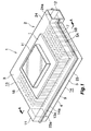
Fig. 1 is a perspective view showing a liquid-cooled-type cooling device according to the present invention; -
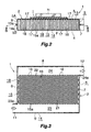
Fig. 2 is a sectional view taken along line A-A ofFig. 1 ; -
Fig. 3 is a sectional view taken along line B-B ofFig. 2 ; -
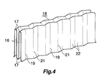
Fig. 4 is a perspective view showing a portion of a fin unit of the liquid-cooled-type cooling device ofFig. 1 ; -
Fig. 5 is an enlarged view of a main portion ofFig. 3 ; -
Fig. 6 is a graph showing the relation between cooling performance and pressure loss, and angles α and β of adjacent first and second fins, wherein the angle α of the first fin is an angle between lines of intersection formed between a horizontal plane and the second-fin-side surfaces of two slant portions of the first fin connecting two adjacent wave trough portions and a wave crest portion located therebetween, and the angle β of the second fin is an angle between lines of intersection formed between the horizontal plane and the first-fin-side surfaces of two slant portions of the second fin connecting two adjacent wave crest portions and a wave trough portion located therebetween; -
Fig. 7 is a graph showing the relation between heat resistance and flow speed of cooling liquid flowing through a cooling-liquid flow channel for an embodiment and a comparative product; -
Fig. 8 is a view corresponding toFig. 5 and showing a modification of the fin unit; -
Fig. 9 is a view corresponding toFig. 5 and showing another modification of the fin unit; and -
Fig. 10 is a view corresponding toFig. 5 and showing fins of a conventional liquid-cooled-type cooling device. - An embodiment of the present invention will next be described with reference to the drawings. Notably, throughout the drawings, like portions and like members are indicated by like reference numerals, and repeated descriptions are omitted.
- In the following description, the upper, lower, lefthand, and right-hand sides of
Fig. 2 will be referred to as "upper," "lower," "left," and "right," respectively. Further, the lower and upper sides ofFig. 3 will be referred to as "front" and "rear," respectively. - In the following description, the term "aluminum" encompasses aluminum alloys in addition to pure aluminum.
-
Figs. 1 to 3 show the overall structure of a liquid-cooled-type cooling device according to the present invention; andFigs. 4 and5 show the structure of a main portion of the cooling device. Notably,Figs. 1 to 3 show a state in which a heat-generating body composed of a semiconductor device is mounted on the liquid-cooled-type cooling device of the present invention. - In
Figs. 1 to 3 , a liquid-cooled-type cooling device 1 has acasing 2 composed of atop wall 3, abottom wall 4, and aperipheral wall 5. Theperipheral wall 5 of thecasing 2 includes aleft side wall 6, which extends in the front-rear direction and stands vertically; a right side wall 7, which extends in the front-rear direction, stands vertically, and is positioned in opposition to theleft side wall 6; arear side wall 8, which extends in the left-right direction and stands vertically; and afront side wall 9, which extends in the left-right direction and stands vertically. In theperipheral wall 5 of thecasing 2, a cooling-liquid inlet 11 is formed at a front end portion of theleft side wall 6 in a leftward projecting condition, and a cooling-liquid outlet 12 is formed at a rear end portion of the right side wall 7 in a rightward projecting condition. The cooling-liquid inlet 11 opens leftward, whereas the cooling-liquid outlet 12 opens rightward. Thecasing 2 is formed of anupper structure member 13 of aluminum and alower structure member 14 of aluminum. Theupper structure member 13 includes thetop wall 3 and an upper peripheral-wall-formation section 5A, which serves as an upper half of theperipheral wall 5. Thelower structure member 14 includes thebottom wall 4 and a lower peripheral-wall-formation section 5B, which serves as a lower half of theperipheral wall 5. A lower end portion of the upper peripheral-wall-formation section 5A of theupper structure member 13 and an upper end portion of the lower peripheral-wall-formation section 5B of thelower structure member 14 have integrally formedoutward flanges outward flanges lower structure members - A cooling-
liquid flow channel 15 is provided within thecasing 2 to be located between theleft side wall 6 and the right side wall 7 and between the cooling-liquid inlet 11 and the cooling-liquid outlet 12. The cooling-liquid flow channel 15 extends in the front-rear direction, and cooling liquid flows through the cooling-liquid flow channel 15 from the front side to the rear side thereof. - A heat-generating body H is attached to the outer surface of the
top wall 3 or thebottom wall 4 of the casing 2 (in the present embodiment, the top wall 3). A plurality offins 16 are provided on the inner surface of a portion of thetop wall 3 facing the cooling-liquid flow channel 15. Thefins 16 project downward from the inner surface, and extend in the front-rear direction (in a flow direction of the cooling liquid within the cooling-liquid flow channel 15). Thefins 16 are spaced from one another in the left-right direction (the width direction of the cooling-liquid flow channel 15). Twoadjacent fins 16 are connected together via aconnection portion 17 at their upper end portions or lower end portions. A plurality of theconnection portions 17 are provided alternately at upper and lower end portions of all thefins 16. Thus, all thefins 16 and theconnection portions 17 constitute a fin unit 18 (seeFig. 4 ). Theconnection portions 17 on the upper side of thefin unit 18 are welded to the inner surface of thetop wall 3 of thecasing 2, and theconnection portions 17 on the lower side of thefin unit 18 are welded to the inner surface of thebottom wall 4 of thecasing 2. - Each
fin 16 of thefin unit 18 has a wavy shape as viewed on a cross section taken along a horizontal plane F perpendicular to the fin height direction of the fins 16 (vertical direction) (seeFig. 2 ), and includes leftward projectingwave crest portions 19 and rightward projectingwave trough portions 21 formed alternately. Thefin unit 18 is manufactured from aluminum through press work, bending work, forging, or the like. -
Fig. 5 shows two adjacent fins of thefin unit 18, wherein the left fin is indicated by 16A, and the right fin is indicated by 16B. As shownFig. 5 , one of the twoadjacent fins left fin 16A) is formed such that the right side surfaces 22a, facing the other fin (in the present embodiment, theright fin 16B), of twoslant portions 22 connecting two adjacentwave crest portions 19 and awave trough portion 21 located between thewave crest portions 19 intersect the above-mentioned horizontal plane F, to thereby form two lines of intersection which intersect each other at a point P1. This point P1 is located on a first straight line L1 extending in the front-rear direction. Meanwhile, the other fin; i.e., theright fin 16B, is formed such that the left side surfaces 22b, facing theleft fin 16A, of twoslant portions 22 connecting two adjacentwave trough portions 21 and awave crest portion 19 located between thewave trough portions 21 intersect the above-mentioned horizontal plane F, to thereby form two lines of intersection which intersect each other at a point P2. This point P2 is located on a second straight line L2 extending in the front-rear direction. The first straight line L1 is located rightward of the second straight line L2. Therefore, as viewed on the above-mentioned horizontal plane F, the point P1 (P2) of thefin 16A (16B) is located on a side toward the adjacentopposite fin 16B (16A) in relation to a single straight line L2 (L1) extending in the front-rear direction (the flow direction of the cooling liquid). Accordingly, in the cooling-liquid flow channel 15, the cooling liquid flows, while meandering, through aflow channel section 15a between the twoadjacent fins 16. Notably, the first straight line L1 and the second straight line L2 may coincide with each other. - Furthermore, in the case of the
left fin 16A, an angle α is formed between the two lines of intersection between the above-mentioned horizontal plane F and the right side surfaces 22a of twoslant portions 22 connecting two adjacentwave trough portions 21 and awave crest portion 19 located therebetween; and in the case of theright fin 16B, an angle β is formed between the two lines of intersection between the above-mentioned horizontal plane F and the left side surfaces 22b of twoslant portions 22 connecting two adjacentwave crest portions 19 and awave trough portion 21 located therebetween. Preferably, each of the angles α and β falls within a range of 110 to 150 degrees. In the case where the angles α and β are excessively small, an excessively large pressure loss is produced when the cooling liquid flows through between the twoadjacent fins 16. In the case where the angles α and β are excessively large, the effect of improving cooling performance may become insufficient. For reference,Fig. 6 shows the relation between the angles α, β, and pressure loss and cooling performance. - Moreover, preferably, the spacing S between the two
adjacent fins adjacent fins - A portion of the interior of the
casing 2 located upstream (frontward) of the cooling-liquid flow channel 15 serves as aninlet header section 23 communicating with the cooling-liquid inlet 11. A portion of the interior of thecasing 2 located downstream (rearward) of the cooling-liquid flow channel 15 serves as anoutlet header section 24 communicating with the cooling-liquid outlet 12. The internal height of theentire casing 2 is uniform; i.e., theinlet header section 23, theoutlet header section 24, and the cooling-liquid flow channel 15 have the same height. Furthermore, each of theinlet header section 23 and theoutlet header section 24 has a constant width (in the front-rear direction) over the entire length thereof. Theinlet header section 23 has a squareinflow end portion 23a, which is located on the side toward theleft side wall 6 and communicates with the cooling-liquid inlet 11, and theoutlet header section 24 has a squareoutflow end portion 24a, which is located on the side toward the right side wall 7 and communicates with the cooling-liquid outlet 12. The width (the width in the front-rear direction) of theinflow end portion 23a of theinlet header section 23 is equal to that of theoutflow end portion 24a of theoutlet header section 24. - The heat-generating body H, which is a semiconductor device, is joined to the outer surface of the
top wall 3 of thecasing 2 via a plate-shaped electrically insulating member I. - In the liquid-cooled-
type cooling device 1 having the above-described configuration, a cooling liquid having flowed from the cooling-liquid inlet 11 into theinlet header section 23 through theinflow end portion 23a dividedly flows into theflow channel sections 15a of the cooling-liquid flow channel 15, each located between twoadjacent fins 16. The cooling liquid then flows rearward through eachflow channel section 15a. - The cooling liquid having flowed rearward along the
flow channel sections 15a of the cooling-liquid flow channel 15 enters theoutlet header section 24, and flows rightward within theoutlet header section 24. The cooling liquid then flows out of the cooling-liquid outlet 12 via theoutflow end portion 24a of theoutlet header section 24 located on the side toward the right side wall 7. - Heat generated from the heat-generating body H is transmitted to the cooling liquid which flows through the
flow channel sections 15a of the cooling-liquid flow channel 15, via the insulating member I, thetop wall 3 of thecasing 2, and thefins 16 of thefin unit 18. The heat-generating body H is thus cooled. - For reference, the relation between heat resistance and flow speed of the cooling liquid flowing through the cooling-
liquid flow channel 15 of the liquid-cooled-type cooling device 1 of the above-described embodiment is shown inFig. 7 by a solid line. Further, the relation between heat resistance and flow speed of the cooling liquid flowing through the cooling-liquid flow channel 15 of a comparative product which includes fins as shown inFig. 10 is shown inFig. 7 by a broken line. The results shown inFig. 7 reveal that the liquid-cooled-type cooling device 1 of the above-described embodiment has an improved cooling performance, as compared with the comparative product having the same structure as the liquid-cooled-type cooling device described in Japanese Patent Application Laid-Open No.2007-201181 - Notably, the results shown in
Fig. 7 were obtained through computer simulation calculation performed under the conditions that the heat load from the heat-generating body H was 50 to 200 W and cooling liquid formed of water and having a temperature of 20 to 30°C was supplied to the cooling-liquid flow channel, while the flow speed of the cooling liquid was changed within a range not greater than 5 m/s. -
Figs. 8 and9 show modifications of the fin unit. Notably, inFigs. 8 and9 as well, of two adjacent fins of the fin unit, the left fin is indicated by 16A, and the right fin is indicated by 16B. - In the case of a
fin unit 30 shown inFig. 8 , each of thefins fins wave crest portions 31 and the rightward projectingwave trough portions 32 is rounded. - Therefore, as viewed on the above-mentioned horizontal plane F, the point P1 of the
left fin 16A, i.e., the intersection between two lines of intersection between the above-mentioned horizontal plane F and the right side surfaces 22a of twoslant portions 22 connecting two adjacentwave crest portions 31 and awave trough portion 32 located therebetween, is located at a position where imaginary lines extending rightward from the right side surfaces 22a of the twoslant portions 22 intersect each other. Further, as viewed on the above-mentioned horizontal plane F, the point P2 of theright fin 16B, i.e., the intersection between two lines of intersection between the above-mentioned horizontal plane F and the left side surfaces 22b of twoslant portions 22 connecting two adjacentwave trough portions 32 and awave crest portion 31 located therebetween, is located at a position where imaginary lines extending leftward from the left side surfaces 22b of the twoslant portions 22 intersect each other. As in the case of thefins Fig. 5 , the points P1 and P2 are located on first and second straight lines L1 and L2, respectively, which extend in the front-rear direction. Since the first straight line L1 is located rightward of the second straight line L2, as viewed on the above-mentioned horizontal plane F, the point P1 (P2) of thefin 16A (16B) is located on a side toward the adjacentopposite fin 16B (16A) in relation to a single straight line L2 (L1) extending in the front-rear direction (the flow direction of the cooling liquid). Notably, the first straight line L1 and the second straight line L2 may coincide with each other. - In the case of a
fin unit 35 shown inFig. 9 , each of thefins fins wave crest portions 36 and the rightward projectingwave trough portions 37 is made flat. - Therefore, as viewed on the above-mentioned horizontal plane F, the point P1 of the
left fin 16A, i.e., the intersection between two lines of intersection between the above-mentioned horizontal plane F and the right side surfaces 22a of twoslant portions 22 connecting two adjacentwave crest portions 36 and awave trough portion 37 located therebetween, is located at a position where imaginary lines extending rightward from the right side surfaces 22a of the twoslant portions 22 intersect each other. Further, as viewed on the above-mentioned horizontal plane F, the point P2 of theright fin 16B, i.e., the intersection between two lines of intersection between the above-mentioned horizontal plane F and the left side surfaces 22b of twoslant portions 22 connecting two adjacentwave trough portions 37 and awave crest portion 36 located therebetween, is located at a position where imaginary lines extending leftward from the left side surfaces 22b of the twoslant portions 22 intersect each other. As in the case of thefins Fig. 5 , the points P1 and P2 are located on first and second straight lines L1 and L2, respectively, which extend in the front-rear direction. Since the first straight line L1 is located rightward of the second straight line L2, as viewed on the above-mentioned horizontal plane F, the point P1 (P2) of thefin 16A (16B) is located on a side toward the adjacentopposite fin 16B (16A) in relation to a single straight line L2 (L1) extending in the front-rear direction (the flow direction of the cooling liquid). Notably, the first straight line L1 and the second straight line L2 may coincide with each other. - In the
fin units Figs. 8 and9 , each of the angles α and β of the left andright fins adjacent fins fin unit 18 shown inFig. 5 . Notably, as described before, the angle α is an angle of theleft fin 16A formed between two lines of intersection between the above-mentioned horizontal plane F and the right side surfaces 22a of twoslant portions 22 connecting two adjacentwave trough portions 21 and awave crest portions 19 located therebetween; and the angle β is an angle of theright fin 16B formed between two lines of intersection between the above-mentioned horizontal plane F and the left side surfaces 22b of twoslant portions 22 connecting two adjacentwave crest portions 19 and awave trough portion 21 located therebetween. - In the above-described embodiments, of all the
fins 16, twoadjacent fins 16 are connected together via theconnection portion 17. However, the structure of the fins is not limited thereto. Thefins 16 may be individually fixed to or integrally formed on the inner surface of a portion (facing the cooling-liquid flow channel 15) of a selected wall (thetop wall 3 or the bottom wall 4) of thecasing 2 onto which a heat-generating body is mounted such that the heat-generating body is in contact with the outer surface of the selected wall. - In the above-described embodiments, a cooling-liquid inlet is formed in one end portion of the
left side wall 6 of theperipheral wall 5 of thecasing 2, and a cooling-liquid outlet is formed in the opposite end portion of the right side wall 7 of theperipheral wall 5 of thecasing 2. However, the arrangement of the cooling-liquid inlet and the cooling-liquid outlet is not limited thereto. The cooling-liquid inlet may be formed in one end portion of a wall selected from theleft side wall 6 and the right side wall 7, and the cooling-liquid outlet may be formed in the opposite end portion of the selected wall. Alternatively, the cooling-liquid inlet and the cooling-liquid outlet may be formed in the top wall or the bottom wall of the casing such that they are spaced from each other.
Claims (7)
- A liquid-cooled-type cooling device comprising a casing which has a top wall, a bottom wall, and a peripheral wall, which has a cooling-liquid inlet and a cooling-liquid outlet formed thereon, and in which a cooling-liquid flow channel is provided between the cooling-liquid inlet and the cooling-liquid outlet, wherein
a plurality of fins projecting into the cooling-liquid flow channel and extending in a flow direction of cooling liquid within the cooling-liquid flow channel are provided on an inner surface of a portion of a wall selected from the top wall and the bottom wall of the casing onto which a heat-generating body is attached such that the heat-generating body is in contact with an outer surface of the selected wall, the potion of the selected wall facing the cooling-liquid flow channel, and the plurality of fins being spaced from one another in a width direction of the cooling-liquid flow channel;
each of the fins has a wavy shape as viewed on a cross section taken along a horizontal plane perpendicular to a height direction of the fins, and has wave crest portions and wave trough portions alternately formed thereon; and
the fins are configured and arranged such that the cooling liquid flows between two adjacent fins while meandering. - A liquid-cooled-type cooling device according to claim 1, wherein a first fin of two adjacent fins is configured such that two lines of intersection formed between the horizontal plane and second-fin-side surfaces of two slant portions connecting two adjacent wave crest portions and a wave trough portion located therebetween intersect each other at a point located on a first straight line; a second fin of the two adjacent fins is configured such that two lines of intersection formed between the horizontal plane and first-fin-side surfaces of two slant portions connecting two adjacent wave trough portions and a wave crest portion located therebetween intersect each other at a point located on a second straight line; and the first straight line and the second straight line coincide with each other or the first straight line is located on a side toward the second fin in relation to the second straight line.
- A liquid-cooled-type cooling device according to claim 2, wherein the wave crest portions and the wave trough portions of each fin are rounded; and, as viewed on the horizontal plane, the point at which the two lines of intersection between the horizontal plane and the second-fin-side surfaces of the two slant portions intersect each other is located at a position at which imaginary lines extending toward the second fin from the second-fin-side surfaces of the two slant portions intersect each other.
- A liquid-cooled-type cooling device according to claim 2, wherein the wave crest portions and the wave trough portions of each fin are made flat; and, as viewed on the horizontal plane, the point at which the two lines of intersection between the horizontal plane and the second-fin-side surfaces of the two slant portions intersect each other is located at a position at which imaginary lines extending toward the second fin from the second-fin-side surfaces of the two slant portions intersect each other.
- A liquid-cooled-type cooling device according to claim 2, wherein the first fin of two adjacent fins is configured such that the two lines of intersection formed between the horizontal plane and the second-fin-side surfaces of two slant portions connecting two adjacent wave trough portions and a wave crest portion located therebetween form an angle of 110 to 150 degrees therebetween; and the second fin of the two adjacent fins is configured such that the two lines of intersection formed between the horizontal plane and the first-fin-side surfaces of two slant portions connecting two adjacent wave crest portions and a wave trough portion located therebetween form an angle of 110 to 150 degrees therebetween.
- A liquid-cooled-type cooling device according to claim 2, wherein two adjacent fins have a spacing of 0.5 mm or greater therebetween.
- A liquid-cooled-type cooling device according to claim 1, wherein two adjacent fins are connected together at their upper end portions or lower end portions via a connection portion, and a plurality of the connection portions are provided alternately at upper and lower end portions of all the fins, whereby all the fins and the connection portions constitute a fin unit; and the connection portions on the upper side of the fin unit are joined to the top wall of the casing, and the connection portions on the lower side of the fin unit are joined to the bottom wall of the casing.
Applications Claiming Priority (1)
| Application Number | Priority Date | Filing Date | Title |
|---|---|---|---|
| JP2009245319A JP2011091301A (en) | 2009-10-26 | 2009-10-26 | Liquid cooling type cooling device |
Publications (2)
| Publication Number | Publication Date |
|---|---|
| EP2315244A1 true EP2315244A1 (en) | 2011-04-27 |
| EP2315244B1 EP2315244B1 (en) | 2020-02-26 |
Family
ID=43530992
Family Applications (1)
| Application Number | Title | Priority Date | Filing Date |
|---|---|---|---|
| EP10188781.8A Active EP2315244B1 (en) | 2009-10-26 | 2010-10-26 | Liquid-cooled-type cooling device |
Country Status (4)
| Country | Link |
|---|---|
| US (1) | US20110094722A1 (en) |
| EP (1) | EP2315244B1 (en) |
| JP (1) | JP2011091301A (en) |
| CN (1) | CN102054808B (en) |
Cited By (4)
| Publication number | Priority date | Publication date | Assignee | Title |
|---|---|---|---|---|
| EP2720262A4 (en) * | 2011-06-07 | 2015-06-17 | Toyota Motor Co Ltd | REFRIGERANT APPARATUS |
| WO2015117706A1 (en) * | 2014-02-07 | 2015-08-13 | Siemens Aktiengesellschaft | Heat sink |
| CN107872942A (en) * | 2016-09-27 | 2018-04-03 | 技嘉科技股份有限公司 | Heat exchange device and method for manufacturing the same |
| DE102021128634A1 (en) | 2021-11-03 | 2023-05-04 | BAB-Bildungsgesellschaft für angewandte Betriebswirtschaft mbH | heat transfer device |
Families Citing this family (31)
| Publication number | Priority date | Publication date | Assignee | Title |
|---|---|---|---|---|
| US8472193B2 (en) * | 2008-07-04 | 2013-06-25 | Kabushiki Kaisha Toyota Jidoshokki | Semiconductor device |
| JP6006480B2 (en) * | 2011-07-29 | 2016-10-12 | 株式会社ティラド | Liquid cooling heat sink |
| CN102878829B (en) * | 2012-10-24 | 2014-01-15 | 深圳市日上光电股份有限公司 | Heat plume generator |
| JP6247090B2 (en) * | 2013-12-26 | 2017-12-13 | 昭和電工株式会社 | Liquid cooling type cooling device and manufacturing method of radiator for liquid cooling type cooling device |
| JP2015144196A (en) * | 2014-01-31 | 2015-08-06 | 三桜工業株式会社 | Cooling device and manufacturing method of cooling device |
| CN105637632B (en) * | 2014-03-20 | 2019-07-23 | 富士电机株式会社 | Cooler and semiconductor module using the same |
| JP6316096B2 (en) * | 2014-05-28 | 2018-04-25 | 昭和電工株式会社 | Liquid cooling system |
| FR3030708B1 (en) * | 2014-12-22 | 2018-02-16 | Airbus Operations Sas | COLD PLATE, IN PARTICULAR A STRUCTURAL PART OF A HEAT-GENERATING COMPONENT EQUIPMENT |
| CN104684368A (en) * | 2015-04-01 | 2015-06-03 | 昆山固德利金属制品有限公司 | Water cooling heat dissipation device |
| JP6548324B2 (en) | 2015-06-30 | 2019-07-24 | 東京ラヂエーター製造株式会社 | Heat exchanger inner fins |
| JP6546521B2 (en) * | 2015-12-11 | 2019-07-17 | 昭和電工株式会社 | Liquid cooling system |
| JPWO2017115436A1 (en) * | 2015-12-28 | 2018-10-18 | 国立大学法人 東京大学 | Heat exchanger |
| JP6735664B2 (en) * | 2016-12-28 | 2020-08-05 | 昭和電工株式会社 | Radiator for liquid cooling type cooling device and manufacturing method thereof |
| JP6663899B2 (en) * | 2017-11-29 | 2020-03-13 | 本田技研工業株式会社 | Cooling system |
| JP7159617B2 (en) * | 2018-05-25 | 2022-10-25 | 富士電機株式会社 | Cooling device, semiconductor module, vehicle and manufacturing method |
| JP6893003B2 (en) * | 2018-08-09 | 2021-06-23 | 富士電機株式会社 | Cooler, semiconductor module |
| DE102018006461B4 (en) * | 2018-08-10 | 2024-01-25 | Eberhard Paul | Heat exchangers with interlocking, acute-angled or pointed-roof-like boards |
| CN109378352A (en) * | 2018-09-06 | 2019-02-22 | 山东航天电子技术研究所 | A microfluidic channel radiator for photovoltaic cells |
| DE102019133238B4 (en) * | 2019-12-05 | 2024-08-29 | Infineon Technologies Ag | FLUID CHANNEL, POWER SEMICONDUCTOR MODULE AND METHOD FOR PRODUCING A FLUID CHANNEL |
| DE102020200110A1 (en) * | 2020-01-08 | 2021-07-08 | Robert Bosch Gesellschaft mit beschränkter Haftung | Cooling device |
| CN212084987U (en) * | 2020-07-09 | 2020-12-04 | 宁波市哈雷换热设备有限公司 | Chip cooler with high bearing capacity |
| US12092399B2 (en) * | 2020-07-14 | 2024-09-17 | Raytheon Company | Chimney cooler design for rugged maximum free convection heat transfer with minimum footprint |
| CN114206063B (en) * | 2020-09-02 | 2024-12-17 | 春鸿电子科技(重庆)有限公司 | Liquid cooling head and liquid cooling type heat radiating device |
| DE112021004801T5 (en) * | 2020-09-14 | 2023-07-27 | T.Rad Co., Ltd. | HEAT EXCHANGER |
| JP7468312B2 (en) * | 2020-11-19 | 2024-04-16 | 株式会社デンソー | Case and Electrical Equipment |
| US12215933B2 (en) * | 2020-11-30 | 2025-02-04 | Dana Canada Corporation | Compact heat exchanger with wavy fin turbulizer |
| JP7499689B2 (en) * | 2020-12-08 | 2024-06-14 | 日立Astemo株式会社 | Wave-shaped heat transfer fin |
| CN113991927B (en) * | 2021-12-10 | 2022-12-06 | 无锡天宝电机有限公司 | Casing structure of motor |
| KR102462316B1 (en) * | 2022-07-19 | 2022-11-03 | 한화시스템 주식회사 | Temperature control device of display device using thermoelectric element |
| DE102022211780A1 (en) * | 2022-11-08 | 2024-05-08 | Robert Bosch Gesellschaft mit beschränkter Haftung | Cooling structure of a fluid-flow cooler |
| CN119550601B (en) * | 2025-01-23 | 2025-04-01 | 长春超维科技产业有限责任公司 | A hot extrusion cooling and shaping device and method for sound insulation and heat insulation materials for automobiles |
Citations (8)
| Publication number | Priority date | Publication date | Assignee | Title |
|---|---|---|---|---|
| US5625229A (en) * | 1994-10-03 | 1997-04-29 | Sumitomo Metal Industries, Ltd. | Heat sink fin assembly for cooling an LSI package |
| JP2004263616A (en) * | 2003-02-28 | 2004-09-24 | Toyo Radiator Co Ltd | Flat tube for egr cooler |
| WO2005038375A1 (en) * | 2003-10-17 | 2005-04-28 | Behr Gmbh & Co. Kg | Heat exchanger in particular for motor vehicles |
| EP1739378A1 (en) * | 2005-06-23 | 2007-01-03 | Autokühler Gmbh & Co. Kg. | Heat exchange element and associated heat exchanger |
| JP2007201181A (en) | 2006-01-26 | 2007-08-09 | Toyota Motor Corp | Power semiconductor element cooling structure |
| DE202007017501U1 (en) * | 2007-12-13 | 2009-04-23 | Autokühler GmbH & Co. KG | Heat exchange element and thus produced heat exchanger |
| WO2009069578A1 (en) * | 2007-11-26 | 2009-06-04 | Kabushiki Kaisha Toyota Jidoshokki | Liquid-cooled cooling device |
| WO2009078289A2 (en) * | 2007-12-14 | 2009-06-25 | Toyota Jidosha Kabushiki Kaisha | Cooling fin and manufacturing method of the cooling fin |
Family Cites Families (10)
| Publication number | Priority date | Publication date | Assignee | Title |
|---|---|---|---|---|
| US3907032A (en) * | 1971-04-27 | 1975-09-23 | United Aircraft Prod | Tube and fin heat exchanger |
| JP4027353B2 (en) * | 2004-09-28 | 2007-12-26 | 三菱電機株式会社 | Cooling structure |
| JP2006125767A (en) * | 2004-10-29 | 2006-05-18 | Tokyo Institute Of Technology | Heat exchanger |
| JP4756585B2 (en) * | 2005-09-09 | 2011-08-24 | 臼井国際産業株式会社 | Heat exchanger tube for heat exchanger |
| CN101573611B (en) * | 2006-12-11 | 2013-06-19 | 株式会社堀场制作所 | Manufacturing method of responsive glass membrane for ion electrode, responsive glass membrane for ion electrode, and ion electrode |
| JP4861840B2 (en) * | 2007-01-26 | 2012-01-25 | アイシン・エィ・ダブリュ株式会社 | Heating element cooling structure and driving device |
| JP2009081220A (en) * | 2007-09-26 | 2009-04-16 | Sumitomo Electric Ind Ltd | Heat dissipation component and heat dissipation structure |
| US9671179B2 (en) * | 2008-01-15 | 2017-06-06 | Showa Denko K.K. | Liquid-cooled-type cooling device |
| JP5023020B2 (en) * | 2008-08-26 | 2012-09-12 | 株式会社豊田自動織機 | Liquid cooling system |
| DE102008044986A1 (en) * | 2008-08-29 | 2010-03-04 | Advanced Micro Devices, Inc., Sunnyvale | A 3-D integrated circuit device with an internal heat distribution function |
-
2009
- 2009-10-26 JP JP2009245319A patent/JP2011091301A/en active Pending
-
2010
- 2010-10-25 US US12/911,357 patent/US20110094722A1/en not_active Abandoned
- 2010-10-26 EP EP10188781.8A patent/EP2315244B1/en active Active
- 2010-10-26 CN CN201010523955.7A patent/CN102054808B/en not_active Expired - Fee Related
Patent Citations (9)
| Publication number | Priority date | Publication date | Assignee | Title |
|---|---|---|---|---|
| US5625229A (en) * | 1994-10-03 | 1997-04-29 | Sumitomo Metal Industries, Ltd. | Heat sink fin assembly for cooling an LSI package |
| JP2004263616A (en) * | 2003-02-28 | 2004-09-24 | Toyo Radiator Co Ltd | Flat tube for egr cooler |
| WO2005038375A1 (en) * | 2003-10-17 | 2005-04-28 | Behr Gmbh & Co. Kg | Heat exchanger in particular for motor vehicles |
| EP1739378A1 (en) * | 2005-06-23 | 2007-01-03 | Autokühler Gmbh & Co. Kg. | Heat exchange element and associated heat exchanger |
| JP2007201181A (en) | 2006-01-26 | 2007-08-09 | Toyota Motor Corp | Power semiconductor element cooling structure |
| WO2009069578A1 (en) * | 2007-11-26 | 2009-06-04 | Kabushiki Kaisha Toyota Jidoshokki | Liquid-cooled cooling device |
| EP2234153A1 (en) * | 2007-11-26 | 2010-09-29 | Kabushiki Kaisha Toyota Jidoshokki | Liquid-cooled cooling device |
| DE202007017501U1 (en) * | 2007-12-13 | 2009-04-23 | Autokühler GmbH & Co. KG | Heat exchange element and thus produced heat exchanger |
| WO2009078289A2 (en) * | 2007-12-14 | 2009-06-25 | Toyota Jidosha Kabushiki Kaisha | Cooling fin and manufacturing method of the cooling fin |
Cited By (5)
| Publication number | Priority date | Publication date | Assignee | Title |
|---|---|---|---|---|
| EP2720262A4 (en) * | 2011-06-07 | 2015-06-17 | Toyota Motor Co Ltd | REFRIGERANT APPARATUS |
| WO2015117706A1 (en) * | 2014-02-07 | 2015-08-13 | Siemens Aktiengesellschaft | Heat sink |
| CN107872942A (en) * | 2016-09-27 | 2018-04-03 | 技嘉科技股份有限公司 | Heat exchange device and method for manufacturing the same |
| CN107872942B (en) * | 2016-09-27 | 2019-09-20 | 技嘉科技股份有限公司 | Heat exchange device and method for manufacturing the same |
| DE102021128634A1 (en) | 2021-11-03 | 2023-05-04 | BAB-Bildungsgesellschaft für angewandte Betriebswirtschaft mbH | heat transfer device |
Also Published As
| Publication number | Publication date |
|---|---|
| CN102054808A (en) | 2011-05-11 |
| CN102054808B (en) | 2016-01-20 |
| JP2011091301A (en) | 2011-05-06 |
| EP2315244B1 (en) | 2020-02-26 |
| US20110094722A1 (en) | 2011-04-28 |
Similar Documents
| Publication | Publication Date | Title |
|---|---|---|
| EP2315244B1 (en) | Liquid-cooled-type cooling device | |
| JP5023020B2 (en) | Liquid cooling system | |
| JP5608787B2 (en) | Liquid cooling system | |
| JP5061065B2 (en) | Liquid cooling system | |
| EP2730879B1 (en) | Liquid-cooled-type cooling device | |
| US9190344B2 (en) | Liquid-cooled-type cooling device | |
| US9534827B2 (en) | Air heat exchanger | |
| CN101978153B (en) | Heat exchanger | |
| JP6548324B2 (en) | Heat exchanger inner fins | |
| JP4777264B2 (en) | Fin type liquid cooling heat sink | |
| US20080121385A1 (en) | Heat dissipation fin for heat exchangers | |
| US20120024511A1 (en) | Intercooler | |
| JP6546521B2 (en) | Liquid cooling system | |
| EP3040670A1 (en) | Heat exchanger, in particular a condenser or a gas cooler | |
| US6942024B2 (en) | Corrugated heat exchange element | |
| CN117337618A (en) | heat sink structure | |
| JP5162538B2 (en) | Liquid cooling system | |
| JP5178872B2 (en) | Cooler | |
| KR20110046302A (en) | Liquid-cooled chillers | |
| US20260085892A1 (en) | Heat exchanger | |
| JP2007216748A (en) | Air guide for vehicle | |
| JPH04257694A (en) | Heat exchanger for vehicle | |
| JP2012077967A (en) | Inner fin | |
| JP2020016360A (en) | Heat exchanger | |
| JP2013072593A (en) | Heat exchanger |
Legal Events
| Date | Code | Title | Description |
|---|---|---|---|
| PUAI | Public reference made under article 153(3) epc to a published international application that has entered the european phase |
Free format text: ORIGINAL CODE: 0009012 |
|
| AK | Designated contracting states |
Kind code of ref document: A1 Designated state(s): AL AT BE BG CH CY CZ DE DK EE ES FI FR GB GR HR HU IE IS IT LI LT LU LV MC MK MT NL NO PL PT RO RS SE SI SK SM TR |
|
| AX | Request for extension of the european patent |
Extension state: BA ME |
|
| 17P | Request for examination filed |
Effective date: 20111027 |
|
| 17Q | First examination report despatched |
Effective date: 20160324 |
|
| RAP1 | Party data changed (applicant data changed or rights of an application transferred) |
Owner name: SHOWA DENKO K.K. |
|
| STAA | Information on the status of an ep patent application or granted ep patent |
Free format text: STATUS: EXAMINATION IS IN PROGRESS |
|
| GRAP | Despatch of communication of intention to grant a patent |
Free format text: ORIGINAL CODE: EPIDOSNIGR1 |
|
| STAA | Information on the status of an ep patent application or granted ep patent |
Free format text: STATUS: GRANT OF PATENT IS INTENDED |
|
| RIC1 | Information provided on ipc code assigned before grant |
Ipc: H01L 23/473 20060101AFI20190911BHEP Ipc: H01L 23/367 20060101ALN20190911BHEP |
|
| RIC1 | Information provided on ipc code assigned before grant |
Ipc: H01L 23/473 20060101AFI20190919BHEP Ipc: H01L 23/367 20060101ALN20190919BHEP |
|
| INTG | Intention to grant announced |
Effective date: 20191008 |
|
| GRAS | Grant fee paid |
Free format text: ORIGINAL CODE: EPIDOSNIGR3 |
|
| GRAA | (expected) grant |
Free format text: ORIGINAL CODE: 0009210 |
|
| STAA | Information on the status of an ep patent application or granted ep patent |
Free format text: STATUS: THE PATENT HAS BEEN GRANTED |
|
| AK | Designated contracting states |
Kind code of ref document: B1 Designated state(s): AL AT BE BG CH CY CZ DE DK EE ES FI FR GB GR HR HU IE IS IT LI LT LU LV MC MK MT NL NO PL PT RO RS SE SI SK SM TR |
|
| REG | Reference to a national code |
Ref country code: GB Ref legal event code: FG4D |
|
| REG | Reference to a national code |
Ref country code: CH Ref legal event code: EP |
|
| REG | Reference to a national code |
Ref country code: AT Ref legal event code: REF Ref document number: 1238673 Country of ref document: AT Kind code of ref document: T Effective date: 20200315 |
|
| REG | Reference to a national code |
Ref country code: IE Ref legal event code: FG4D |
|
| REG | Reference to a national code |
Ref country code: DE Ref legal event code: R096 Ref document number: 602010063218 Country of ref document: DE |
|
| PG25 | Lapsed in a contracting state [announced via postgrant information from national office to epo] |
Ref country code: NO Free format text: LAPSE BECAUSE OF FAILURE TO SUBMIT A TRANSLATION OF THE DESCRIPTION OR TO PAY THE FEE WITHIN THE PRESCRIBED TIME-LIMIT Effective date: 20200526 Ref country code: RS Free format text: LAPSE BECAUSE OF FAILURE TO SUBMIT A TRANSLATION OF THE DESCRIPTION OR TO PAY THE FEE WITHIN THE PRESCRIBED TIME-LIMIT Effective date: 20200226 Ref country code: FI Free format text: LAPSE BECAUSE OF FAILURE TO SUBMIT A TRANSLATION OF THE DESCRIPTION OR TO PAY THE FEE WITHIN THE PRESCRIBED TIME-LIMIT Effective date: 20200226 |
|
| REG | Reference to a national code |
Ref country code: NL Ref legal event code: MP Effective date: 20200226 |
|
| REG | Reference to a national code |
Ref country code: LT Ref legal event code: MG4D |
|
| PG25 | Lapsed in a contracting state [announced via postgrant information from national office to epo] |
Ref country code: LV Free format text: LAPSE BECAUSE OF FAILURE TO SUBMIT A TRANSLATION OF THE DESCRIPTION OR TO PAY THE FEE WITHIN THE PRESCRIBED TIME-LIMIT Effective date: 20200226 Ref country code: SE Free format text: LAPSE BECAUSE OF FAILURE TO SUBMIT A TRANSLATION OF THE DESCRIPTION OR TO PAY THE FEE WITHIN THE PRESCRIBED TIME-LIMIT Effective date: 20200226 Ref country code: IS Free format text: LAPSE BECAUSE OF FAILURE TO SUBMIT A TRANSLATION OF THE DESCRIPTION OR TO PAY THE FEE WITHIN THE PRESCRIBED TIME-LIMIT Effective date: 20200626 Ref country code: HR Free format text: LAPSE BECAUSE OF FAILURE TO SUBMIT A TRANSLATION OF THE DESCRIPTION OR TO PAY THE FEE WITHIN THE PRESCRIBED TIME-LIMIT Effective date: 20200226 Ref country code: GR Free format text: LAPSE BECAUSE OF FAILURE TO SUBMIT A TRANSLATION OF THE DESCRIPTION OR TO PAY THE FEE WITHIN THE PRESCRIBED TIME-LIMIT Effective date: 20200527 Ref country code: BG Free format text: LAPSE BECAUSE OF FAILURE TO SUBMIT A TRANSLATION OF THE DESCRIPTION OR TO PAY THE FEE WITHIN THE PRESCRIBED TIME-LIMIT Effective date: 20200526 |
|
| PG25 | Lapsed in a contracting state [announced via postgrant information from national office to epo] |
Ref country code: NL Free format text: LAPSE BECAUSE OF FAILURE TO SUBMIT A TRANSLATION OF THE DESCRIPTION OR TO PAY THE FEE WITHIN THE PRESCRIBED TIME-LIMIT Effective date: 20200226 |
|
| PG25 | Lapsed in a contracting state [announced via postgrant information from national office to epo] |
Ref country code: PT Free format text: LAPSE BECAUSE OF FAILURE TO SUBMIT A TRANSLATION OF THE DESCRIPTION OR TO PAY THE FEE WITHIN THE PRESCRIBED TIME-LIMIT Effective date: 20200719 Ref country code: LT Free format text: LAPSE BECAUSE OF FAILURE TO SUBMIT A TRANSLATION OF THE DESCRIPTION OR TO PAY THE FEE WITHIN THE PRESCRIBED TIME-LIMIT Effective date: 20200226 Ref country code: CZ Free format text: LAPSE BECAUSE OF FAILURE TO SUBMIT A TRANSLATION OF THE DESCRIPTION OR TO PAY THE FEE WITHIN THE PRESCRIBED TIME-LIMIT Effective date: 20200226 Ref country code: RO Free format text: LAPSE BECAUSE OF FAILURE TO SUBMIT A TRANSLATION OF THE DESCRIPTION OR TO PAY THE FEE WITHIN THE PRESCRIBED TIME-LIMIT Effective date: 20200226 Ref country code: SK Free format text: LAPSE BECAUSE OF FAILURE TO SUBMIT A TRANSLATION OF THE DESCRIPTION OR TO PAY THE FEE WITHIN THE PRESCRIBED TIME-LIMIT Effective date: 20200226 Ref country code: EE Free format text: LAPSE BECAUSE OF FAILURE TO SUBMIT A TRANSLATION OF THE DESCRIPTION OR TO PAY THE FEE WITHIN THE PRESCRIBED TIME-LIMIT Effective date: 20200226 Ref country code: SM Free format text: LAPSE BECAUSE OF FAILURE TO SUBMIT A TRANSLATION OF THE DESCRIPTION OR TO PAY THE FEE WITHIN THE PRESCRIBED TIME-LIMIT Effective date: 20200226 Ref country code: DK Free format text: LAPSE BECAUSE OF FAILURE TO SUBMIT A TRANSLATION OF THE DESCRIPTION OR TO PAY THE FEE WITHIN THE PRESCRIBED TIME-LIMIT Effective date: 20200226 Ref country code: ES Free format text: LAPSE BECAUSE OF FAILURE TO SUBMIT A TRANSLATION OF THE DESCRIPTION OR TO PAY THE FEE WITHIN THE PRESCRIBED TIME-LIMIT Effective date: 20200226 |
|
| REG | Reference to a national code |
Ref country code: AT Ref legal event code: MK05 Ref document number: 1238673 Country of ref document: AT Kind code of ref document: T Effective date: 20200226 |
|
| REG | Reference to a national code |
Ref country code: DE Ref legal event code: R097 Ref document number: 602010063218 Country of ref document: DE |
|
| PLBE | No opposition filed within time limit |
Free format text: ORIGINAL CODE: 0009261 |
|
| STAA | Information on the status of an ep patent application or granted ep patent |
Free format text: STATUS: NO OPPOSITION FILED WITHIN TIME LIMIT |
|
| PG25 | Lapsed in a contracting state [announced via postgrant information from national office to epo] |
Ref country code: AT Free format text: LAPSE BECAUSE OF FAILURE TO SUBMIT A TRANSLATION OF THE DESCRIPTION OR TO PAY THE FEE WITHIN THE PRESCRIBED TIME-LIMIT Effective date: 20200226 Ref country code: IT Free format text: LAPSE BECAUSE OF FAILURE TO SUBMIT A TRANSLATION OF THE DESCRIPTION OR TO PAY THE FEE WITHIN THE PRESCRIBED TIME-LIMIT Effective date: 20200226 |
|
| 26N | No opposition filed |
Effective date: 20201127 |
|
| PG25 | Lapsed in a contracting state [announced via postgrant information from national office to epo] |
Ref country code: SI Free format text: LAPSE BECAUSE OF FAILURE TO SUBMIT A TRANSLATION OF THE DESCRIPTION OR TO PAY THE FEE WITHIN THE PRESCRIBED TIME-LIMIT Effective date: 20200226 Ref country code: PL Free format text: LAPSE BECAUSE OF FAILURE TO SUBMIT A TRANSLATION OF THE DESCRIPTION OR TO PAY THE FEE WITHIN THE PRESCRIBED TIME-LIMIT Effective date: 20200226 |
|
| REG | Reference to a national code |
Ref country code: CH Ref legal event code: PL |
|
| GBPC | Gb: european patent ceased through non-payment of renewal fee |
Effective date: 20201026 |
|
| PG25 | Lapsed in a contracting state [announced via postgrant information from national office to epo] |
Ref country code: MC Free format text: LAPSE BECAUSE OF FAILURE TO SUBMIT A TRANSLATION OF THE DESCRIPTION OR TO PAY THE FEE WITHIN THE PRESCRIBED TIME-LIMIT Effective date: 20200226 Ref country code: LU Free format text: LAPSE BECAUSE OF NON-PAYMENT OF DUE FEES Effective date: 20201026 |
|
| REG | Reference to a national code |
Ref country code: BE Ref legal event code: MM Effective date: 20201031 |
|
| PG25 | Lapsed in a contracting state [announced via postgrant information from national office to epo] |
Ref country code: FR Free format text: LAPSE BECAUSE OF NON-PAYMENT OF DUE FEES Effective date: 20201031 |
|
| PG25 | Lapsed in a contracting state [announced via postgrant information from national office to epo] |
Ref country code: GB Free format text: LAPSE BECAUSE OF NON-PAYMENT OF DUE FEES Effective date: 20201026 Ref country code: LI Free format text: LAPSE BECAUSE OF NON-PAYMENT OF DUE FEES Effective date: 20201031 Ref country code: BE Free format text: LAPSE BECAUSE OF NON-PAYMENT OF DUE FEES Effective date: 20201031 Ref country code: CH Free format text: LAPSE BECAUSE OF NON-PAYMENT OF DUE FEES Effective date: 20201031 |
|
| PG25 | Lapsed in a contracting state [announced via postgrant information from national office to epo] |
Ref country code: IE Free format text: LAPSE BECAUSE OF NON-PAYMENT OF DUE FEES Effective date: 20201026 |
|
| PG25 | Lapsed in a contracting state [announced via postgrant information from national office to epo] |
Ref country code: TR Free format text: LAPSE BECAUSE OF FAILURE TO SUBMIT A TRANSLATION OF THE DESCRIPTION OR TO PAY THE FEE WITHIN THE PRESCRIBED TIME-LIMIT Effective date: 20200226 Ref country code: MT Free format text: LAPSE BECAUSE OF FAILURE TO SUBMIT A TRANSLATION OF THE DESCRIPTION OR TO PAY THE FEE WITHIN THE PRESCRIBED TIME-LIMIT Effective date: 20200226 Ref country code: CY Free format text: LAPSE BECAUSE OF FAILURE TO SUBMIT A TRANSLATION OF THE DESCRIPTION OR TO PAY THE FEE WITHIN THE PRESCRIBED TIME-LIMIT Effective date: 20200226 |
|
| PG25 | Lapsed in a contracting state [announced via postgrant information from national office to epo] |
Ref country code: MK Free format text: LAPSE BECAUSE OF FAILURE TO SUBMIT A TRANSLATION OF THE DESCRIPTION OR TO PAY THE FEE WITHIN THE PRESCRIBED TIME-LIMIT Effective date: 20200226 Ref country code: AL Free format text: LAPSE BECAUSE OF FAILURE TO SUBMIT A TRANSLATION OF THE DESCRIPTION OR TO PAY THE FEE WITHIN THE PRESCRIBED TIME-LIMIT Effective date: 20200226 |
|
| REG | Reference to a national code |
Ref country code: DE Ref legal event code: R082 Ref document number: 602010063218 Country of ref document: DE Representative=s name: CBDL PATENTANWAELTE GBR, DE Ref country code: DE Ref legal event code: R082 Ref document number: 602010063218 Country of ref document: DE Representative=s name: CBDL PATENTANWAELTE EGBR, DE |
|
| REG | Reference to a national code |
Ref country code: DE Ref legal event code: R081 Ref document number: 602010063218 Country of ref document: DE Owner name: RESONAC CORP., JP Free format text: FORMER OWNER: SHOWA DENKO K.K., TOKYO, JP |
|
| PGFP | Annual fee paid to national office [announced via postgrant information from national office to epo] |
Ref country code: DE Payment date: 20230830 Year of fee payment: 14 |
|
| REG | Reference to a national code |
Ref country code: DE Ref legal event code: R119 Ref document number: 602010063218 Country of ref document: DE |
|
| PG25 | Lapsed in a contracting state [announced via postgrant information from national office to epo] |
Ref country code: DE Free format text: LAPSE BECAUSE OF NON-PAYMENT OF DUE FEES Effective date: 20250501 |