EP2314894A2 - Synchronisiereinrichtung - Google Patents
Synchronisiereinrichtung Download PDFInfo
- Publication number
- EP2314894A2 EP2314894A2 EP10177756A EP10177756A EP2314894A2 EP 2314894 A2 EP2314894 A2 EP 2314894A2 EP 10177756 A EP10177756 A EP 10177756A EP 10177756 A EP10177756 A EP 10177756A EP 2314894 A2 EP2314894 A2 EP 2314894A2
- Authority
- EP
- European Patent Office
- Prior art keywords
- sliding sleeve
- synchronizer body
- synchronizer
- angular position
- mechanical engagement
- Prior art date
- Legal status (The legal status is an assumption and is not a legal conclusion. Google has not performed a legal analysis and makes no representation as to the accuracy of the status listed.)
- Granted
Links
Images
Classifications
-
- F—MECHANICAL ENGINEERING; LIGHTING; HEATING; WEAPONS; BLASTING
- F16—ENGINEERING ELEMENTS AND UNITS; GENERAL MEASURES FOR PRODUCING AND MAINTAINING EFFECTIVE FUNCTIONING OF MACHINES OR INSTALLATIONS; THERMAL INSULATION IN GENERAL
- F16D—COUPLINGS FOR TRANSMITTING ROTATION; CLUTCHES; BRAKES
- F16D23/00—Details of mechanically-actuated clutches not specific for one distinct type
- F16D23/02—Arrangements for synchronisation, also for power-operated clutches
- F16D23/04—Arrangements for synchronisation, also for power-operated clutches with an additional friction clutch
-
- F—MECHANICAL ENGINEERING; LIGHTING; HEATING; WEAPONS; BLASTING
- F16—ENGINEERING ELEMENTS AND UNITS; GENERAL MEASURES FOR PRODUCING AND MAINTAINING EFFECTIVE FUNCTIONING OF MACHINES OR INSTALLATIONS; THERMAL INSULATION IN GENERAL
- F16D—COUPLINGS FOR TRANSMITTING ROTATION; CLUTCHES; BRAKES
- F16D23/00—Details of mechanically-actuated clutches not specific for one distinct type
- F16D23/02—Arrangements for synchronisation, also for power-operated clutches
- F16D23/04—Arrangements for synchronisation, also for power-operated clutches with an additional friction clutch
- F16D23/06—Arrangements for synchronisation, also for power-operated clutches with an additional friction clutch and a blocking mechanism preventing the engagement of the main clutch prior to synchronisation
-
- F—MECHANICAL ENGINEERING; LIGHTING; HEATING; WEAPONS; BLASTING
- F16—ENGINEERING ELEMENTS AND UNITS; GENERAL MEASURES FOR PRODUCING AND MAINTAINING EFFECTIVE FUNCTIONING OF MACHINES OR INSTALLATIONS; THERMAL INSULATION IN GENERAL
- F16D—COUPLINGS FOR TRANSMITTING ROTATION; CLUTCHES; BRAKES
- F16D23/00—Details of mechanically-actuated clutches not specific for one distinct type
- F16D23/02—Arrangements for synchronisation, also for power-operated clutches
- F16D23/04—Arrangements for synchronisation, also for power-operated clutches with an additional friction clutch
- F16D23/06—Arrangements for synchronisation, also for power-operated clutches with an additional friction clutch and a blocking mechanism preventing the engagement of the main clutch prior to synchronisation
- F16D2023/0631—Sliding sleeves; Details thereof
-
- F—MECHANICAL ENGINEERING; LIGHTING; HEATING; WEAPONS; BLASTING
- F16—ENGINEERING ELEMENTS AND UNITS; GENERAL MEASURES FOR PRODUCING AND MAINTAINING EFFECTIVE FUNCTIONING OF MACHINES OR INSTALLATIONS; THERMAL INSULATION IN GENERAL
- F16D—COUPLINGS FOR TRANSMITTING ROTATION; CLUTCHES; BRAKES
- F16D23/00—Details of mechanically-actuated clutches not specific for one distinct type
- F16D23/02—Arrangements for synchronisation, also for power-operated clutches
- F16D23/04—Arrangements for synchronisation, also for power-operated clutches with an additional friction clutch
- F16D23/06—Arrangements for synchronisation, also for power-operated clutches with an additional friction clutch and a blocking mechanism preventing the engagement of the main clutch prior to synchronisation
- F16D2023/0637—Details relating to the hub member on which the sliding is arranged
-
- F—MECHANICAL ENGINEERING; LIGHTING; HEATING; WEAPONS; BLASTING
- F16—ENGINEERING ELEMENTS AND UNITS; GENERAL MEASURES FOR PRODUCING AND MAINTAINING EFFECTIVE FUNCTIONING OF MACHINES OR INSTALLATIONS; THERMAL INSULATION IN GENERAL
- F16D—COUPLINGS FOR TRANSMITTING ROTATION; CLUTCHES; BRAKES
- F16D23/00—Details of mechanically-actuated clutches not specific for one distinct type
- F16D23/02—Arrangements for synchronisation, also for power-operated clutches
- F16D23/04—Arrangements for synchronisation, also for power-operated clutches with an additional friction clutch
- F16D23/06—Arrangements for synchronisation, also for power-operated clutches with an additional friction clutch and a blocking mechanism preventing the engagement of the main clutch prior to synchronisation
- F16D2023/0656—Details of the tooth structure; Arrangements of teeth
Definitions
- the invention relates to a synchronizer for manual transmission.
- Known manual transmissions have synchronizers in order to facilitate the changing of the individual switching stages.
- the circumferential speed of a gear wheel of the peripheral speed of the gear shaft is adjusted by means of various elements of the synchronizer and then made a positive connection between the gear shaft and this gear.
- the synchronizer body is an important part of the synchronizer. Through the synchronizer body, the transmission shaft and the sliding sleeve of the synchronizer are rotatably connected to each other.
- the synchronizer body is on the one hand in the circumferential direction positively connected via a trained on its hub spline or tooth profile with the transmission shaft, and on the other hand via an external toothing of its sleeve carrier slidably receives the sliding sleeve at its outer diameter along the longitudinal center axis of the transmission shaft.
- By means of a synchronizing device it is thus possible optionally to connect the gear wheel arranged on the left of this synchronizing unit or the gear wheel arranged on the right of this synchronizing device to the gear shaft in a form-fitting manner.
- the synchronizer body must be constructively designed so that the sliding sleeve arranged on it can be moved axially to the left and to the right and that z. B. at a Doppelkonussynchronisation on both sides of the drive cam of the inner synchronizer ring can be positively guided. Since generally the left and the right gear wheel have the same running connection elements, and the synchronizer body is formed symmetrically in the rule. In certain cases, however, the sliding sleeve, based on a plane perpendicular to the axial direction, designed asymmetrically, for example, for a different meshing engagement in the first gear. In this case, the sliding sleeve must be mounted in the axially correct orientation.
- the present invention has for its object to provide a synchronizer for a manual transmission, in which a mounting of an asymmetrically designed in the axial direction of the sliding sleeve is possible without errors.
- a synchronizer for a transmission comprising a rotatably mounted on a transmission shaft synchronizer body and on the synchronizer body with respect to the transmission shaft in the axial direction and slidable with the synchronizer body via a gearing mechanically interacting sliding sleeve, wherein the sliding sleeve based on a plane perpendicular to the transmission shaft is constructed asymmetrically and thus has a first end face and a different, opposite second end face and directed along a central axis, wherein a mechanical engagement of sliding sleeve and synchronizer body is designed so that a sliding of the sliding sleeve on the synchronizer body ever after sliding along the central axis only with the first or with the second end face is possible.
- the invention is based on the recognition that a faulty assembly by rotating the asymmetric sliding sleeve relative to the synchronizer body can lead to considerable additional effort and costs. In fact, it can be seen that an additional manufacturing effort to ensure the avoidance of incorrect assembly is justified, although at first e.g. an optical marking of the different sides of the sliding sleeve must appear sufficient.
- the invention thus proposes, for the first time, to preclude incorrect assembly by means of adapted mechanical engagement.
- the mechanical engagement in the toothing is formed by a recess and a block tooth corresponding to the recess, wherein the block tooth is larger than a tooth of the toothing.
- the mechanical intervention can thus be ensured comparatively easily by a rather slight adaptation of the toothing.
- a desired angular position is predetermined between the sliding sleeve and the synchronizer body, in which the sliding sleeve and the synchronizer body must be oriented towards one another in the circumferential direction, so that the sliding sleeve can be pushed onto the synchronizer body, with an initial angular position of the mechanical engagement being selected relative to the desired angular position in that the mechanical engagement when the sliding sleeve is rotated by 180 degrees about an axis perpendicular to its central axis is no longer coincident with the initial angular position, although the desired angular position is maintained.
- the desired angular position is predetermined by a locking device, by which the sliding sleeve and the synchronizer body are latched together.
- the locking device has three mutually offset by 120 degrees Rastierstellen.
- the mechanical engagement is formed from three engagement points distributed over the circumference of the sliding sleeve and the synchronizer body, wherein at least one of the angles formed between the three engagement points is less than 120 degrees.
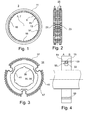
- FIG. 1 shows a sliding sleeve 3.
- the sliding sleeve 3 is constructed in a ring around a central axis 5 through a central axis 7.
- the sliding sleeve 3 has an inner side 9 and an outer side 11. on the inside 9 a sleeve toothing 13 is arranged.
- the sleeve toothing 13 is formed from teeth 14. Offset in the circumferential direction by 120 degrees, the sleeve toothing 13 Rastierstellen 15 as wells, in the not shown, pressed by means of springs and in locking grooves 33 (see FIG. 3 ) guided locking means 53 (see FIG. 4 ) can intervene.
- a recess 17 is formed in the socket toothing 13.
- the recess 17 is arranged in the circumferential direction relative to the angular position of the Rastierstellen 15 so that it results in a changed angular position when the sliding sleeve 3 is rotated about an arbitrary axis perpendicular to the central axis 7 by 180 degrees.
- FIG. 2 shows a longitudinal section through the sliding sleeve 3.
- the socket toothing 13 is constructed asymmetrically, ie that the socket toothing in a first region A adjacent to a first end face 21 of the toothing in a second region B adjacent to the second end face 23rd different.
- FIG. 2 also shows a at the Outside 11 along the circumference shaped groove 25 into which a shift lever for axial displacement of the sliding sleeve 3 can engage.
- FIG. 3 shows a synchronizer body 31, on which the sliding sleeve 3 can be pushed in the axial direction.
- the synchronizer body 31 is also constructed in a ring around a synchronizer body center axis 36 leading through a synchronizer body center 35.
- the synchronizer body 31 has a synchronizer body outside 37 and a synchronizer body inside 39.
- a synchronizer toothing 43 is formed of synchronizer teeth 45, which corresponds to the sleeve toothing 13 and whereby the toothing 51 of the synchronizer 1 is formed (see FIG. 4 ).
- Radially outward leading 31 locking grooves 33 are formed in the synchronizer body, in which locking means 53 are guided, which engage in the arranged as recesses in the sleeve toothing 13 Rastierstellen 15.
- the Rastierstellen 15 are arranged offset from one another by 120 degrees on the circumference. This results in the circumferential direction of a desired angular position in which the sliding sleeve 3 is postponed to the synchronizer body 31.
- the Rastierstellen 15 come with the locking grooves 33 only at three angular positions to cover.
- the Rastierstellen 15 form with the locking grooves 33 and the locking means 53 is a locking device 55.
- the synchronizer toothing 43 has a block tooth 47 which is larger than the synchronizer teeth 45.
- the block tooth 47 corresponds to the recess 17 of the sliding sleeve 3.
- This is a mechanical engagement 59 formed (see FIG. 4 ).
- the mechanical engagement 59 is now chosen in its position and symmetry so that it allows a sliding of the sliding sleeve 3 on the synchronizer body 31 only in a fixed orientation of the end faces 21, 23.
- the recess 17 only comes into line with the block tooth 47 when the sliding sleeve 3 is oriented in relation to its end faces 21, 23 in a predetermined direction to the synchronizer body 31.
- this is the recess 17 and the block tooth 47 is not arranged symmetrically to the distribution of the locking device 55.
Landscapes
- Engineering & Computer Science (AREA)
- General Engineering & Computer Science (AREA)
- Mechanical Engineering (AREA)
- Mechanical Operated Clutches (AREA)
Abstract
Description
- Die Erfindung betrifft eine Synchronisiereinrichtung für Schaltgetriebe.
- Bekannte handgeschaltete Getriebe weisen Synchronisiereinrichtungen auf, um das Wechseln der einzelnen Schaltstufen zu erleichtern. Beim Schaltvorgang wird mittels verschiedener Elemente der Synchronisiereinrichtung die Umfangsgeschwindigkeit eines Gangrades der Umfangsgeschwindigkeit der Getriebewelle angepasst und dann eine formschlüssige Verbindung zwischen der Getriebewelle und diesem Gangrad hergestellt. Der Synchronkörper ist dabei ein wichtiger Bestandteil der Synchronisiereinrichtung. Durch den Synchronkörper sind die Getriebewelle und die Schiebemuffe der Synchronisiereinrichtung drehfest miteinander verbunden. Das erfolgt in der Regel dadurch, dass der Synchronkörper einerseits in Umfangsrichtung formschlüssig über ein an seiner Nabe ausgebildetes Keilprofil oder Verzahnungsprofil mit der Getriebewelle verbunden ist, und andererseits über eine Außenverzahnung seines Muffenträgers die Schiebemuffe an seinem Außendurchmesser entlang der Längsmittelachse der Getriebewelle verschiebbar aufnimmt. Es ist in Schaltgetrieben üblich, die Synchronisiereinrichtung auf der Getriebewelle zwischen zwei Gangrädern anzuordnen. Über eine Synchronisiereinrichtung kann demzufolge wahlweise das links von dieser Synchronisiereinheit angeordnete Gangrad oder das rechts von dieser Synchronisiereinrichtung angeordnete Gangrad formschlüssig mit der Getriebewelle verbunden werden. Der Synchronkörper muss konstruktiv so ausgebildet sein, dass die auf ihm angeordnete Schiebemuffe axial nach links und rechts verschoben werden kann und dass z. B. bei einer Doppelkonussynchronisation an beiden Seiten die Mitnehmernocken des inneren Synchronringes formschlüssig geführt werden können. Da in der Regel das linke und das rechte Gangrad gleich ausgeführte Anschlusselemente aufweisen, ist auch der Synchronkörper in der Regel symmetrisch ausgebildet. In bestimmten Fällen ist aber die Schiebemuffe, bezogen auf eine Ebene senkrecht zur axialen Richtung, asymmetrisch gestaltet, z.B. für einen unterschiedlichen Verzahnungseingriff beim ersten Gang. In diesem Fall muss die Schiebemuffe in axial richtiger Orientierung montiert werden.
- Der vorliegenden Erfindung liegt die Aufgabe zugrunde, eine Synchronisiereinrichtung für ein Schaltgetriebe anzugeben, bei dem eine Montage einer in axialer Richtung asymmetrisch gestalteten Schiebemuffe fehlerfrei möglich ist.
- Die Aufgabe wird erfindungsgemäß gelöst durch Angabe einer Synchronisiereinrichtung für ein Schaltgetriebe, umfassend einen auf einer Getriebewelle drehfest montierbaren Synchronkörper und eine auf den Synchronkörper bezogen auf die Getriebewelle in axialer Richtung aufschiebbare und mit dem Synchronkörper über eine Verzahnung mechanisch wechselwirkende Schiebemuffe, wobei die Schiebemuffe bezogen auf eine Ebene senkrecht zur Getriebewelle asymmetrisch aufgebaut ist und somit eine erste Stirnseite und eine davon verschiedene, gegenüberliegende zweite Stirnseite aufweist sowie entlang einer Mittelachse gerichtet ist, wobei ein mechanischer Eingriff von Schiebemuffe und Synchronkörper so gestaltet ist, dass ein Aufschieben der Schiebemuffe auf den Synchronkörper je nach Schieberichtung entlang der Mittelachse nur entweder mit der ersten oder mit der zweiten Stirnseite möglich ist.
- Die Erfindung geht von der Erkenntnis aus, dass eine Fehlmontage durch ein Verdrehen der asymmetrischen Schiebemuffe relativ zum Synchronkörper zu erheblichem Mehraufwand und Kosten führen kann. Tatsächlich zeigt sich, dass ein fertigungstechnischer Mehraufwand zur Sicherstellung der Vermeidung einer Fehlmontage gerechtfertigt ist, obwohl zunächst z.B. eine optische Kennzeichnung der verschiedenen Seiten der Schiebemuffe als ausreichend erscheinen muss. Die Erfindung schlägt somit erstmals vor, durch einen angepassten mechanischen Eingriff eine Fehlmontage auszuschließen.
- Vorzugsweise ist der mechanische Eingriff in der Verzahnung durch eine Aussparung und einen mit der Aussparung korrespondierenden Blockzahn gebildet, wobei der Blockzahn größer ist, als ein Zahn der Verzahnung. Der mechanische Eingriff kann somit vergleichsweise einfach durch eine eher geringfügige Anpassung der Verzahnung sichergestellt werden.
- Bevorzugt ist zwischen Schiebemuffe und Synchronkörper eine Soll-Winkelposition vorgegeben, in der die Schiebemuffe und der Synchronkörper zueinander in Umfangsrichtung orientiert sein müssen, damit die Schiebemuffe auf den Synchronkörper aufschiebbar ist, wobei eine Ausgangswinkelposition des mechanischen Eingriffs relativ zu zur Soll-Winkelposition so gewählt ist, dass der mechanische Eingriff bei einem Verdrehen der Schiebemuffe um 180 Grad um eine senkrecht durch ihre Mittelachse gedachten Achse mit der Ausgangswinkelposition nicht mehr in Deckung ist, obwohl die Soll-Winkelposition eingehalten bleibt.
- Weiter bevorzugt ist die Soll-Winkelposition durch eine Rastiereinrichtung vorgegeben, durch die die Schiebemuffe und der Synchronkörper miteinander verrastbar sind. Vorzugsweise weist dabei die Rastiereinrichtung drei zueinander um 120 Grad versetzte Rastierstellen aufweist. Bevorzugtermaßen ist der mechanische Eingriff aus drei über den Umfang der Schiebemuffe und des Synchronkörpers verteilten Eingriffsstellen gebildet, wobei mindestens einer der zwischen den drei Eingriffstellen gebildeten Winkel kleiner als 120 Grad ist.
- Die Erfindung wird anhand von Ausführungsbeispielen näher erläutert. Es zeigen:
- Figur 1:
- eine Schiebemuffe in einer Aufsicht,
- Figur2:
- eine Schiebemuffe in einem Längsschnitt,
- Figur 3:
- einen Synchronkörper in einer Aufsicht,
- Figur 4:
- eine schematische Darstellung einer Synchronisiereinrichtung.
-
Figur 1 zeigt eine Schiebemuffe 3. Die Schiebemuffe 3 ist ringförmig um eine durch einen Mittelpunkt 5 führende Mittelachse 7 aufgebaut. Die Schiebemuffe 3 weist eine Innenseite 9 und eine Außenseite 11 auf. auf der Innenseite 9 ist eine Muffenverzahnung 13 angeordnet. Die Muffenverzahnung 13 ist aus Zähnen 14 gebildet. In Umfangsrichtung um jeweils 120 Grad versetzt weist die Muffenverzahnung 13 Rastierstellen 15 als Vertiefungen auf, in die nicht dargestellte, mittels Federn angedrückte und in Rastnuten 33 (sieheFigur 3 ) geführte Rastmittel 53 (sieheFigur 4 ) eingreifen können. Weiterhin ist in der Muffenverzahnung 13 eine Aussparung 17 gebildet. Die Aussparung 17 ist in Umfangsrichtung relativ zur Winkellage der Rastierstellen 15 so angeordnet, dass sich für sie eine veränderte Winkellage ergibt, wenn die Schiebemuffe 3 um eine beliebige Achse senkrecht zur Mittelachse 7 um 180 Grad gedreht wird. -
Figur 2 zeigt einen Längsschnitt durch die Schiebemuffe 3. Schematisch ist angedeutet, dass die Muffenverzahnung 13 asymmetrisch aufgebaut ist, d.h. dass sich die Muffenverzahnung in einem ersten Bereich A angrenzend an eine erste Stirnseite 21 von der Verzahnung in einem zweiten Bereich B angrenzend an die zweite Stirnseite 23 unterscheidet.Figur 2 zeigt auch eine an der Außenseite 11 entlang des Umfangs geformte Nut 25, in die ein Schalthebel zur axialen Verschiebung der Schiebemuffe 3 eingreifen kann. -
Figur 3 zeigt einen Synchronkörper 31, auf den die Schiebemuffe 3 in axialer Richtung aufschiebbar ist. Der Synchronkörper 31 ist auch ringförmig um einen durch einen Synchronkörpermittelpunkt 35 führende Synchronkörpermittelachse 36 aufgebaut. Der Synchronkörper 31 weist eine Synchronkörperaußenseite 37 und eine Synchronkörperinnenseite 39 auf. Auf der Synchronkörperinnenseite 39 ist eine Innenverzahnung 41 gebildet, über die der Synchronkörper 31 fest mit einer nicht dargestellten Getriebewelle verbindbar ist, die sich im montierten Zustand entlang der Synchronkörpermittelachse 37 erstreckt. Auf der Synchronkörperaußenseite 37 ist eine Synchronkörperverzahnung 43 aus Synchronkörperzähnen 45 gebildet, die mit der Muffenverzahnung 13 korrespondiert und wodurch die Verzahnung 51 der Synchronisiereinrichtung 1 gebildet wird (sieheFigur 4 ). Radial nach außen führend sind im Synchronkörper 31 Rastnuten 33 gebildet, in denen Rastmittel 53 geführt werden, die in die als Vertiefungen in der Muffenverzahnung 13 angeordneten Rastierstellen 15 eingreifen. Die Rastierstellen 15 sind zueinander um 120 Grad versetzt am Umfang angeordnet. Hierdurch ergibt sich in Umfangsrichtung eine Soll-Winkelposition, in der die Schiebemuffe 3 auf den Synchronkörper 31 aufzuschieben ist. Entsprechend der 120 Grad Verteilung kommen die Rastierstellen 15 mit den Rastnuten 33 nur bei drei Winkellagen zur Deckung. Die Rastierstellen 15 bilden mit den Rastnuten 33 und den Rastmitteln 53 eine Rastiereinrichtung 55. Weiterhin weist die Synchronkörperverzahnung 43 einen Blockzahn 47 auf, der größer ist, als die Synchronkörperzähne 45. Der Blockzahn 47 korrespondiert mit der Aussparung 17 der Schiebemuffe 3. Hierdurch wird ein mechanischer Eingriff 59 gebildet (sieheFigur 4 ). Der mechanische Eingriff 59 ist nunmehr in seiner Lage und Symmetrie so gewählt, dass er ein Aufschieben der Schiebemuffe 3 auf den Synchronkörper 31 nur in einer festgelegten Orientierung der Stirnseiten 21, 23 zulässt. Mit anderen Worten, die Aussparung 17 kommt mit dem Blockzahn 47 nur dann zur Deckung, wenn die Schiebemuffe 3 bezogen auf ihre Stirnseiten 21, 23 in einer vorgegeben Richtung zum Synchronkörper 31 orientiert ist. Im vorliegenden Beispiel ist hierzu die Aussparung 17 und der Blockzahn 47 nicht symmetrisch zur Verteilung der Rastiereinrichtung 55 angeordnet. Bei einer Drehung der Schiebemuffe 3 um eine zur Mittelachse 7 senkrechten Achse um 180 Grad kann somit zwar die Soll-Winkelposition in Umfangsrichtung aufgrund der 120 Grad Verteilung der Rastiereinrichtung 55 eingestellt werden, der mechanische Eingriff 59 wird aber nicht zur Deckung gebracht und verhindert ein Aufschieben der Schiebemuffe 3. Somit ist ausgeschlossen, dass die asymmetrisch ausgeführte Schiebemuffe 3 mit einer falschen Orientierung montiert wird. -
- 1
- Synchronisiereinrichtung
- 2
- -
- 3
- Schiebemuffe
- 4
- -
- 5
- Mittelpunkt
- 6
- -
- 7
- Mittelachse
- 8
- -
- 9
- Innenseite
- 10
- -
- 11
- Außenseite
- 12
- -
- 13
- Muffenverzahnung
- 14
- Zähne
- 15
- Rastierstellen
- 16
- -
- 17
- Aussparung
- 21
- Stirnseite
- 22
- -
- 23
- Stirnseite
- 24
- -
- 25
- Nut
- 31
- Synchronkörper
- 32
- -
- 33
- Rastnuten
- 34
- -
- 35
- Synchronkörpermittelpunkt
- 36
- Synchronkörpermittelachse
- 37
- Synchronkörperaußenseite
- 38
- -
- 39
- Synchronkörperinnenseite
- 40
- -
- 41
- Innenverzahnung
- 42
- -
- 43
- Synchronkörperverzahnung
- 44
- -
- 45
- Synchronkörperzähne
- 46
- -
- 47
- Blockzahn
- 51
- Verzahnung
- 52
- -
- 53
- Rastmittel
- 59
- Eingriff
Claims (6)
- Synchronisiereinrichtung für ein Schaltgetriebe, umfassend einen auf einer Getriebewelle drehfest montierbaren Synchronkörper und eine auf den Synchronkörper bezogen auf die Getriebewelle in axialer Richtung aufschiebbare und mit dem Synchronkörper über eine Verzahnung mechanisch wechselwirkende Schiebemuffe, wobei die Schiebemuffe bezogen auf eine Ebene senkrecht zur Getriebewelle asymmetrisch aufgebaut ist und somit eine erste Stirnseite und eine davon verschiedene, gegenüberliegende zweite Stirnseite aufweist sowie entlang einer Mittelachse gerichtet ist, dadurch gekennzeichnet, dass ein mechanischer Eingriff von Schiebemuffe und Synchronkörper so gestaltet ist, dass ein Aufschieben der Schiebemuffe auf den Synchronkörper je nach Schieberichtung entlang der Mittelachse nur entweder mit der ersten oder mit der zweiten Stirnseite möglich ist.
- Synchronisiereinrichtung nach Anspruch 1, bei der der mechanische Eingriff in der Verzahnung durch eine Aussparung und einen mit der Aussparung korrespondierenden Blockzahn gebildet ist, wobei der Blockzahn größer ist, als ein Zahn der Verzahnung.
- Synchronisiereinrichtung nach Anspruch 1, bei der zwischen Schiebemuffe und Synchronkörper eine Soll-Winkelposition vorgegeben ist, in der die Schiebemuffe und der Synchronkörper zueinander in Umfangsrichtung orientiert sein müssen, damit die Schiebemuffe auf den Synchronkörper aufschiebbar ist, wobei eine Ausgangswinkelposition des mechanischen Eingriffs relativ zu zur Soll-Winkelposition so gewählt ist, dass der mechanische Eingriff bei einem Verdrehen der Schiebemuffe um 180 Grad um eine senkrecht durch ihre Mittelachse gedachten Achse mit der Ausgangswinkelposition nicht mehr in Deckung ist, obwohl die Soll-Winkelposition eingehalten bleibt.
- Synchronisiereinrichtung nach Anspruch 3, bei der die Soll-Winkelposition durch eine Rastiereinrichtung vorgegeben ist, durch die die Schiebemuffe und der Synchronkörper miteinander verrastbar sind.
- Synchronisiereinrichtung nach Anspruch 4, wobei die Rastiereinrichtung drei zueinander um 120 Grad versetzte Rastierstellen aufweist.
- Synchronisiereinrichtung nach Anspruch 5, wobei der mechanische Eingriff aus drei über den Umfang der Schiebemuffe und des Synchronkörpers verteilten Eingriffsstellen gebildet ist, wobei die jeweils zwischen den Eingriffstellen und den Rastierstellen gebildeten Winkel nicht alle gleich sind.
Applications Claiming Priority (1)
| Application Number | Priority Date | Filing Date | Title |
|---|---|---|---|
| DE200910050525 DE102009050525A1 (de) | 2009-10-23 | 2009-10-23 | Synchronisiereinrichtung |
Publications (3)
| Publication Number | Publication Date |
|---|---|
| EP2314894A2 true EP2314894A2 (de) | 2011-04-27 |
| EP2314894A3 EP2314894A3 (de) | 2014-01-29 |
| EP2314894B1 EP2314894B1 (de) | 2014-11-12 |
Family
ID=43479406
Family Applications (1)
| Application Number | Title | Priority Date | Filing Date |
|---|---|---|---|
| EP20100177756 Not-in-force EP2314894B1 (de) | 2009-10-23 | 2010-09-21 | Synchronisiereinrichtung |
Country Status (2)
| Country | Link |
|---|---|
| EP (1) | EP2314894B1 (de) |
| DE (1) | DE102009050525A1 (de) |
Family Cites Families (4)
| Publication number | Priority date | Publication date | Assignee | Title |
|---|---|---|---|---|
| IT1185796B (it) * | 1985-06-04 | 1987-11-18 | Fiat Auto Spa | Cambio di velocita a ingranaggi sempre in fresa per autoveicoli |
| JPH1082431A (ja) * | 1996-09-06 | 1998-03-31 | Isuzu Motors Ltd | 変速機の同期装置 |
| DE60106462T2 (de) * | 2001-11-09 | 2005-11-03 | Ford Global Technologies, LLC, Dearborn | Synchronisierungseinrichtung in einem Fahrzeuggetriebe |
| FR2927386B1 (fr) * | 2008-02-12 | 2010-04-30 | Peugeot Citroen Automobiles Sa | Dispositif de synchronisation multi-cones pour boite de vitesses |
-
2009
- 2009-10-23 DE DE200910050525 patent/DE102009050525A1/de not_active Withdrawn
-
2010
- 2010-09-21 EP EP20100177756 patent/EP2314894B1/de not_active Not-in-force
Also Published As
| Publication number | Publication date |
|---|---|
| DE102009050525A1 (de) | 2011-04-28 |
| EP2314894B1 (de) | 2014-11-12 |
| EP2314894A3 (de) | 2014-01-29 |
Similar Documents
| Publication | Publication Date | Title |
|---|---|---|
| EP2012035B1 (de) | Arretierung | |
| WO2011000849A1 (de) | Synchronisiervorrichtung für ein schaltgetriebe | |
| WO2015124154A2 (de) | Kupplung mit flanschverbindung | |
| EP3339682A1 (de) | Schieberad für eine schaltgetriebeanordnung | |
| WO2014094768A1 (de) | Schiebemuffe eines gangräderwechselgetriebes | |
| DE60106462T2 (de) | Synchronisierungseinrichtung in einem Fahrzeuggetriebe | |
| AT503895A2 (de) | Schiebemuffe | |
| DE102007030507A1 (de) | Schiebemuffe | |
| DE102006060535A1 (de) | Synchronisiereinrichtung für ein Schaltgetriebe | |
| EP2314894B1 (de) | Synchronisiereinrichtung | |
| DE102016204156B3 (de) | Schiebemuffe zum Schalten von Gangstufen eines Schaltgetriebes | |
| DE102015201708A1 (de) | Schiebemuffe mit einer Außenverzahnung | |
| DE102012216419A1 (de) | Kupplungskörper für eine Synchronisierungseinheit | |
| DE102012014830A1 (de) | Schaltgetriebe für Kraftfahrzeuge | |
| DE102011075504A1 (de) | Arretierung | |
| DE102014205778B3 (de) | Synchroneinrichtung mit versetzter Synchronkontur | |
| DE102015113614B4 (de) | Synchronring eines Schaltgetriebes sowie Schaltgetriebe mit einem solchen Synchronring | |
| DE102022110072B4 (de) | Synchronisierungsvorrichtung für ein Gangwechselgetriebe | |
| DE102012008219A1 (de) | Ventiltrieb einer Brennkraftmaschine | |
| DE102005061977A1 (de) | Schiebemuffe | |
| EP3685063A1 (de) | Synchronisierungseinheit | |
| DE102018131841B4 (de) | Verfahren zur Montage einer Nabenanordnung | |
| WO2017088868A1 (de) | Flacher endstop in schiebemuffe | |
| DE102015015363A1 (de) | Getriebeelement für ein Getriebe eines Kraftwagens | |
| DE102012217987B4 (de) | Synchronisiereinrichtung |
Legal Events
| Date | Code | Title | Description |
|---|---|---|---|
| PUAI | Public reference made under article 153(3) epc to a published international application that has entered the european phase |
Free format text: ORIGINAL CODE: 0009012 |
|
| 17P | Request for examination filed |
Effective date: 20100921 |
|
| AK | Designated contracting states |
Kind code of ref document: A2 Designated state(s): AL AT BE BG CH CY CZ DE DK EE ES FI FR GB GR HR HU IE IS IT LI LT LU LV MC MK MT NL NO PL PT RO SE SI SK SM TR |
|
| AX | Request for extension of the european patent |
Extension state: BA ME RS |
|
| RAP1 | Party data changed (applicant data changed or rights of an application transferred) |
Owner name: SCHAEFFLER TECHNOLOGIES AG & CO. KG |
|
| PUAL | Search report despatched |
Free format text: ORIGINAL CODE: 0009013 |
|
| AK | Designated contracting states |
Kind code of ref document: A3 Designated state(s): AL AT BE BG CH CY CZ DE DK EE ES FI FR GB GR HR HU IE IS IT LI LT LU LV MC MK MT NL NO PL PT RO SE SI SK SM TR |
|
| AX | Request for extension of the european patent |
Extension state: BA ME RS |
|
| RIC1 | Information provided on ipc code assigned before grant |
Ipc: F16D 23/04 20060101AFI20131220BHEP Ipc: F16D 23/06 20060101ALI20131220BHEP |
|
| RAP1 | Party data changed (applicant data changed or rights of an application transferred) |
Owner name: SCHAEFFLER TECHNOLOGIES GMBH & CO. KG |
|
| GRAJ | Information related to disapproval of communication of intention to grant by the applicant or resumption of examination proceedings by the epo deleted |
Free format text: ORIGINAL CODE: EPIDOSDIGR1 |
|
| GRAP | Despatch of communication of intention to grant a patent |
Free format text: ORIGINAL CODE: EPIDOSNIGR1 |
|
| GRAP | Despatch of communication of intention to grant a patent |
Free format text: ORIGINAL CODE: EPIDOSNIGR1 |
|
| INTG | Intention to grant announced |
Effective date: 20140704 |
|
| RBV | Designated contracting states (corrected) |
Designated state(s): AL AT BE BG CH CY CZ DE DK EE ES FI FR GB GR HR HU IE IS IT LI LT LU LV MC MK MT NL NO PL PT RO SE SI SK SM TR |
|
| GRAS | Grant fee paid |
Free format text: ORIGINAL CODE: EPIDOSNIGR3 |
|
| GRAA | (expected) grant |
Free format text: ORIGINAL CODE: 0009210 |
|
| AK | Designated contracting states |
Kind code of ref document: B1 Designated state(s): AL AT BE BG CH CY CZ DE DK EE ES FI FR GB GR HR HU IE IS IT LI LT LU LV MC MK MT NL NO PL PT RO SE SI SK SM TR |
|
| REG | Reference to a national code |
Ref country code: GB Ref legal event code: FG4D Free format text: NOT ENGLISH |
|
| REG | Reference to a national code |
Ref country code: CH Ref legal event code: EP |
|
| REG | Reference to a national code |
Ref country code: AT Ref legal event code: REF Ref document number: 695963 Country of ref document: AT Kind code of ref document: T Effective date: 20141115 |
|
| REG | Reference to a national code |
Ref country code: IE Ref legal event code: FG4D Free format text: LANGUAGE OF EP DOCUMENT: GERMAN |
|
| REG | Reference to a national code |
Ref country code: DE Ref legal event code: R096 Ref document number: 502010008229 Country of ref document: DE Effective date: 20141224 |
|
| RAP2 | Party data changed (patent owner data changed or rights of a patent transferred) |
Owner name: SCHAEFFLER TECHNOLOGIES AG & CO. KG |
|
| REG | Reference to a national code |
Ref country code: DE Ref legal event code: R081 Ref document number: 502010008229 Country of ref document: DE Owner name: SCHAEFFLER TECHNOLOGIES AG & CO. KG, DE Free format text: FORMER OWNER: SCHAEFFLER TECHNOLOGIES GMBH & CO. KG, 91074 HERZOGENAURACH, DE Effective date: 20150122 |
|
| REG | Reference to a national code |
Ref country code: NL Ref legal event code: VDEP Effective date: 20141112 |
|
| PG25 | Lapsed in a contracting state [announced via postgrant information from national office to epo] |
Ref country code: PT Free format text: LAPSE BECAUSE OF FAILURE TO SUBMIT A TRANSLATION OF THE DESCRIPTION OR TO PAY THE FEE WITHIN THE PRESCRIBED TIME-LIMIT Effective date: 20150312 Ref country code: NO Free format text: LAPSE BECAUSE OF FAILURE TO SUBMIT A TRANSLATION OF THE DESCRIPTION OR TO PAY THE FEE WITHIN THE PRESCRIBED TIME-LIMIT Effective date: 20150212 Ref country code: NL Free format text: LAPSE BECAUSE OF FAILURE TO SUBMIT A TRANSLATION OF THE DESCRIPTION OR TO PAY THE FEE WITHIN THE PRESCRIBED TIME-LIMIT Effective date: 20141112 Ref country code: ES Free format text: LAPSE BECAUSE OF FAILURE TO SUBMIT A TRANSLATION OF THE DESCRIPTION OR TO PAY THE FEE WITHIN THE PRESCRIBED TIME-LIMIT Effective date: 20141112 Ref country code: LT Free format text: LAPSE BECAUSE OF FAILURE TO SUBMIT A TRANSLATION OF THE DESCRIPTION OR TO PAY THE FEE WITHIN THE PRESCRIBED TIME-LIMIT Effective date: 20141112 Ref country code: FI Free format text: LAPSE BECAUSE OF FAILURE TO SUBMIT A TRANSLATION OF THE DESCRIPTION OR TO PAY THE FEE WITHIN THE PRESCRIBED TIME-LIMIT Effective date: 20141112 Ref country code: IS Free format text: LAPSE BECAUSE OF FAILURE TO SUBMIT A TRANSLATION OF THE DESCRIPTION OR TO PAY THE FEE WITHIN THE PRESCRIBED TIME-LIMIT Effective date: 20150312 |
|
| PG25 | Lapsed in a contracting state [announced via postgrant information from national office to epo] |
Ref country code: CY Free format text: LAPSE BECAUSE OF FAILURE TO SUBMIT A TRANSLATION OF THE DESCRIPTION OR TO PAY THE FEE WITHIN THE PRESCRIBED TIME-LIMIT Effective date: 20141112 Ref country code: SE Free format text: LAPSE BECAUSE OF FAILURE TO SUBMIT A TRANSLATION OF THE DESCRIPTION OR TO PAY THE FEE WITHIN THE PRESCRIBED TIME-LIMIT Effective date: 20141112 Ref country code: LV Free format text: LAPSE BECAUSE OF FAILURE TO SUBMIT A TRANSLATION OF THE DESCRIPTION OR TO PAY THE FEE WITHIN THE PRESCRIBED TIME-LIMIT Effective date: 20141112 Ref country code: HR Free format text: LAPSE BECAUSE OF FAILURE TO SUBMIT A TRANSLATION OF THE DESCRIPTION OR TO PAY THE FEE WITHIN THE PRESCRIBED TIME-LIMIT Effective date: 20141112 Ref country code: PL Free format text: LAPSE BECAUSE OF FAILURE TO SUBMIT A TRANSLATION OF THE DESCRIPTION OR TO PAY THE FEE WITHIN THE PRESCRIBED TIME-LIMIT Effective date: 20141112 |
|
| PG25 | Lapsed in a contracting state [announced via postgrant information from national office to epo] |
Ref country code: SK Free format text: LAPSE BECAUSE OF FAILURE TO SUBMIT A TRANSLATION OF THE DESCRIPTION OR TO PAY THE FEE WITHIN THE PRESCRIBED TIME-LIMIT Effective date: 20141112 Ref country code: RO Free format text: LAPSE BECAUSE OF FAILURE TO SUBMIT A TRANSLATION OF THE DESCRIPTION OR TO PAY THE FEE WITHIN THE PRESCRIBED TIME-LIMIT Effective date: 20141112 Ref country code: CZ Free format text: LAPSE BECAUSE OF FAILURE TO SUBMIT A TRANSLATION OF THE DESCRIPTION OR TO PAY THE FEE WITHIN THE PRESCRIBED TIME-LIMIT Effective date: 20141112 Ref country code: EE Free format text: LAPSE BECAUSE OF FAILURE TO SUBMIT A TRANSLATION OF THE DESCRIPTION OR TO PAY THE FEE WITHIN THE PRESCRIBED TIME-LIMIT Effective date: 20141112 Ref country code: DK Free format text: LAPSE BECAUSE OF FAILURE TO SUBMIT A TRANSLATION OF THE DESCRIPTION OR TO PAY THE FEE WITHIN THE PRESCRIBED TIME-LIMIT Effective date: 20141112 |
|
| REG | Reference to a national code |
Ref country code: DE Ref legal event code: R097 Ref document number: 502010008229 Country of ref document: DE |
|
| PLBE | No opposition filed within time limit |
Free format text: ORIGINAL CODE: 0009261 |
|
| STAA | Information on the status of an ep patent application or granted ep patent |
Free format text: STATUS: NO OPPOSITION FILED WITHIN TIME LIMIT |
|
| 26N | No opposition filed |
Effective date: 20150813 |
|
| PG25 | Lapsed in a contracting state [announced via postgrant information from national office to epo] |
Ref country code: IT Free format text: LAPSE BECAUSE OF FAILURE TO SUBMIT A TRANSLATION OF THE DESCRIPTION OR TO PAY THE FEE WITHIN THE PRESCRIBED TIME-LIMIT Effective date: 20141112 |
|
| PG25 | Lapsed in a contracting state [announced via postgrant information from national office to epo] |
Ref country code: SI Free format text: LAPSE BECAUSE OF FAILURE TO SUBMIT A TRANSLATION OF THE DESCRIPTION OR TO PAY THE FEE WITHIN THE PRESCRIBED TIME-LIMIT Effective date: 20141112 |
|
| PG25 | Lapsed in a contracting state [announced via postgrant information from national office to epo] |
Ref country code: MC Free format text: LAPSE BECAUSE OF FAILURE TO SUBMIT A TRANSLATION OF THE DESCRIPTION OR TO PAY THE FEE WITHIN THE PRESCRIBED TIME-LIMIT Effective date: 20141112 Ref country code: LU Free format text: LAPSE BECAUSE OF FAILURE TO SUBMIT A TRANSLATION OF THE DESCRIPTION OR TO PAY THE FEE WITHIN THE PRESCRIBED TIME-LIMIT Effective date: 20150921 |
|
| REG | Reference to a national code |
Ref country code: CH Ref legal event code: PL |
|
| GBPC | Gb: european patent ceased through non-payment of renewal fee |
Effective date: 20150921 |
|
| REG | Reference to a national code |
Ref country code: IE Ref legal event code: MM4A |
|
| REG | Reference to a national code |
Ref country code: FR Ref legal event code: ST Effective date: 20160531 |
|
| PG25 | Lapsed in a contracting state [announced via postgrant information from national office to epo] |
Ref country code: GB Free format text: LAPSE BECAUSE OF NON-PAYMENT OF DUE FEES Effective date: 20150921 Ref country code: IE Free format text: LAPSE BECAUSE OF NON-PAYMENT OF DUE FEES Effective date: 20150921 Ref country code: LI Free format text: LAPSE BECAUSE OF NON-PAYMENT OF DUE FEES Effective date: 20150930 Ref country code: CH Free format text: LAPSE BECAUSE OF NON-PAYMENT OF DUE FEES Effective date: 20150930 |
|
| PG25 | Lapsed in a contracting state [announced via postgrant information from national office to epo] |
Ref country code: FR Free format text: LAPSE BECAUSE OF NON-PAYMENT OF DUE FEES Effective date: 20150930 |
|
| REG | Reference to a national code |
Ref country code: AT Ref legal event code: MM01 Ref document number: 695963 Country of ref document: AT Kind code of ref document: T Effective date: 20150921 |
|
| PG25 | Lapsed in a contracting state [announced via postgrant information from national office to epo] |
Ref country code: AT Free format text: LAPSE BECAUSE OF NON-PAYMENT OF DUE FEES Effective date: 20150921 |
|
| PG25 | Lapsed in a contracting state [announced via postgrant information from national office to epo] |
Ref country code: MT Free format text: LAPSE BECAUSE OF FAILURE TO SUBMIT A TRANSLATION OF THE DESCRIPTION OR TO PAY THE FEE WITHIN THE PRESCRIBED TIME-LIMIT Effective date: 20141112 |
|
| PG25 | Lapsed in a contracting state [announced via postgrant information from national office to epo] |
Ref country code: BG Free format text: LAPSE BECAUSE OF FAILURE TO SUBMIT A TRANSLATION OF THE DESCRIPTION OR TO PAY THE FEE WITHIN THE PRESCRIBED TIME-LIMIT Effective date: 20141112 Ref country code: HU Free format text: LAPSE BECAUSE OF FAILURE TO SUBMIT A TRANSLATION OF THE DESCRIPTION OR TO PAY THE FEE WITHIN THE PRESCRIBED TIME-LIMIT; INVALID AB INITIO Effective date: 20100921 Ref country code: SM Free format text: LAPSE BECAUSE OF FAILURE TO SUBMIT A TRANSLATION OF THE DESCRIPTION OR TO PAY THE FEE WITHIN THE PRESCRIBED TIME-LIMIT Effective date: 20141112 |
|
| PG25 | Lapsed in a contracting state [announced via postgrant information from national office to epo] |
Ref country code: GR Free format text: LAPSE BECAUSE OF FAILURE TO SUBMIT A TRANSLATION OF THE DESCRIPTION OR TO PAY THE FEE WITHIN THE PRESCRIBED TIME-LIMIT Effective date: 20141112 |
|
| PG25 | Lapsed in a contracting state [announced via postgrant information from national office to epo] |
Ref country code: BE Free format text: LAPSE BECAUSE OF NON-PAYMENT OF DUE FEES Effective date: 20150930 |
|
| PG25 | Lapsed in a contracting state [announced via postgrant information from national office to epo] |
Ref country code: TR Free format text: LAPSE BECAUSE OF FAILURE TO SUBMIT A TRANSLATION OF THE DESCRIPTION OR TO PAY THE FEE WITHIN THE PRESCRIBED TIME-LIMIT Effective date: 20141112 |
|
| PG25 | Lapsed in a contracting state [announced via postgrant information from national office to epo] |
Ref country code: MK Free format text: LAPSE BECAUSE OF FAILURE TO SUBMIT A TRANSLATION OF THE DESCRIPTION OR TO PAY THE FEE WITHIN THE PRESCRIBED TIME-LIMIT Effective date: 20141112 |
|
| PG25 | Lapsed in a contracting state [announced via postgrant information from national office to epo] |
Ref country code: AL Free format text: LAPSE BECAUSE OF FAILURE TO SUBMIT A TRANSLATION OF THE DESCRIPTION OR TO PAY THE FEE WITHIN THE PRESCRIBED TIME-LIMIT Effective date: 20141112 |
|
| P01 | Opt-out of the competence of the unified patent court (upc) registered |
Effective date: 20230522 |
|
| PGFP | Annual fee paid to national office [announced via postgrant information from national office to epo] |
Ref country code: DE Payment date: 20231121 Year of fee payment: 14 |
|
| REG | Reference to a national code |
Ref country code: DE Ref legal event code: R119 Ref document number: 502010008229 Country of ref document: DE |
|
| PG25 | Lapsed in a contracting state [announced via postgrant information from national office to epo] |
Ref country code: DE Free format text: LAPSE BECAUSE OF NON-PAYMENT OF DUE FEES Effective date: 20250401 |