EP2314841A2 - Spark-ignition internal combustion engine - Google Patents
Spark-ignition internal combustion engine Download PDFInfo
- Publication number
- EP2314841A2 EP2314841A2 EP10188314A EP10188314A EP2314841A2 EP 2314841 A2 EP2314841 A2 EP 2314841A2 EP 10188314 A EP10188314 A EP 10188314A EP 10188314 A EP10188314 A EP 10188314A EP 2314841 A2 EP2314841 A2 EP 2314841A2
- Authority
- EP
- European Patent Office
- Prior art keywords
- piston
- cylinder
- engine
- spark
- stroke length
- Prior art date
- Legal status (The legal status is an assumption and is not a legal conclusion. Google has not performed a legal analysis and makes no representation as to the accuracy of the status listed.)
- Granted
Links
- 238000002485 combustion reaction Methods 0.000 title claims abstract description 75
- 230000006835 compression Effects 0.000 claims abstract description 29
- 238000007906 compression Methods 0.000 claims abstract description 29
- 239000000446 fuel Substances 0.000 claims description 11
- 238000002347 injection Methods 0.000 claims description 4
- 239000007924 injection Substances 0.000 claims description 4
- 238000006073 displacement reaction Methods 0.000 description 21
- 238000011160 research Methods 0.000 description 9
- 230000006866 deterioration Effects 0.000 description 4
- 238000012886 linear function Methods 0.000 description 3
- 238000005259 measurement Methods 0.000 description 3
- 230000002000 scavenging effect Effects 0.000 description 3
- 230000015572 biosynthetic process Effects 0.000 description 2
- 238000010586 diagram Methods 0.000 description 2
- 238000012986 modification Methods 0.000 description 2
- 230000004048 modification Effects 0.000 description 2
- 230000000994 depressogenic effect Effects 0.000 description 1
- 239000000203 mixture Substances 0.000 description 1
- 230000002028 premature Effects 0.000 description 1
Images


Classifications
-
- F—MECHANICAL ENGINEERING; LIGHTING; HEATING; WEAPONS; BLASTING
- F02—COMBUSTION ENGINES; HOT-GAS OR COMBUSTION-PRODUCT ENGINE PLANTS
- F02B—INTERNAL-COMBUSTION PISTON ENGINES; COMBUSTION ENGINES IN GENERAL
- F02B23/00—Other engines characterised by special shape or construction of combustion chambers to improve operation
- F02B23/08—Other engines characterised by special shape or construction of combustion chambers to improve operation with positive ignition
- F02B23/10—Other engines characterised by special shape or construction of combustion chambers to improve operation with positive ignition with separate admission of air and fuel into cylinder
- F02B23/104—Other engines characterised by special shape or construction of combustion chambers to improve operation with positive ignition with separate admission of air and fuel into cylinder the injector being placed on a side position of the cylinder
-
- Y—GENERAL TAGGING OF NEW TECHNOLOGICAL DEVELOPMENTS; GENERAL TAGGING OF CROSS-SECTIONAL TECHNOLOGIES SPANNING OVER SEVERAL SECTIONS OF THE IPC; TECHNICAL SUBJECTS COVERED BY FORMER USPC CROSS-REFERENCE ART COLLECTIONS [XRACs] AND DIGESTS
- Y02—TECHNOLOGIES OR APPLICATIONS FOR MITIGATION OR ADAPTATION AGAINST CLIMATE CHANGE
- Y02T—CLIMATE CHANGE MITIGATION TECHNOLOGIES RELATED TO TRANSPORTATION
- Y02T10/00—Road transport of goods or passengers
- Y02T10/10—Internal combustion engine [ICE] based vehicles
- Y02T10/12—Improving ICE efficiencies
Landscapes
- Engineering & Computer Science (AREA)
- Chemical & Material Sciences (AREA)
- Combustion & Propulsion (AREA)
- Mechanical Engineering (AREA)
- General Engineering & Computer Science (AREA)
- Combustion Methods Of Internal-Combustion Engines (AREA)
Abstract
Description
- The present invention relates to a spark-ignition internal combustion engine, and particularly to a spark-ignition internal combustion engine comprising an engine body configured to have a high geometric compression ratio,
- Heretofore, in a spark-ignition internal combustion engine, there have been conducted various researches on a configuration of an engine body. For example,
JP 2007-154827A - Meanwhile, it is conventionally known that a higher geometric compression ratio of an engine body provides enhanced engine thermal efficiency and improved fuel economy.
- The conventional spark-ignition internal combustion engine disclosed in the above patent publication makes it possible to delay collision between a flame and a piston. However, in an engine body configured to have a high geometric compression ratio, if a height of a combustion chamber is simply increased to delay the collision, engine output power is liable to become insufficient.
- Specifically, if it is attempted to increase the height of the combustion chamber while setting the geometric compression ratio of the engine body to a. high value, a stroke length of the piston becomes longer along with the increase in height of the combustion chamber. If the stroke length becomes longer under the same engine displacement, a bore diameter of a cylinder becomes relatively smaller. If the bore diameter of the cylinder becomes smaller, a diameter of an intake valve provided in a cylinder head defining a ceiling of the combustion chamber becomes smaller and thereby an opening area of the intake valve becomes smaller. The smaller opening area of the intake valve is liable to cause failing to charge a sufficient amount of intake air during an increase in engine speed, resulting in lowering of engine output power.
- it is an object of the present invention to provide a spark-ignition internal combustion engine capable of ensuring engine output power while setting a geometric compression ratio of an engine body to a high value,
- In order to achieve this object, the present invention provides a spark-ignition internal combustion engine which comprises: an engine body including a cylinder, a piston adapted to be reciprocatingly moved within the cylinder, and a cylinder head provided on the cylinder to define a combustion chamber in cooperation with a top surface of the piston; two intake valves provided in the cylinder head and each capable of shutting off an inflow of air into the cylinder; two exhaust valves provided in the cylinder head and each capable of shutting off an outflow of exhaust gas from the cylinder; a spark plug provided in the cylinder head to face the combustion chamber; and a fuel injection valve provided in the cylinder head to face the combustion chamber, wherein: a geometric compression ratio of the engine body is set to 14 or more; each of a clearance between the top surface of the piston located at a top dead center position and a lower surface of each of the intake valves in a full-closed state, and a clearance between the top surface of the piston located at the top dead center position and a lower surface of each of the exhaust valves in a full-closed state, is set to 5 mm or more; and a stroke length S of the piston is set to satisfy the following relationship: S ≤ 0.977 × B + 18.2, where B is a bore diameter of the cylinder.
- This spark-ignition internal combustion engine makes it possible to largely ensure an opening area of the intake valve and therefore a cylinder air charge amount to achieve high engine output power, while setting the geometric compression ratio of the engine body to 14 or more.
-
-
FIG. 1 is a schematic block diagram of a spark-ignition internal combustion engine according to one embodiment of the present invention. -
FIG. 2 is a schematic perspective view showing a structure around a combustion chamber. -
FIG. 3 is a schematic sectional, view showing a structure around the combustion chamber when a piston is located at a top dead center position. -
FIG. 4 is a schematic perspective view showing a structure of a two-point spark-ignition internal combustion engine around a combustion chamber. -
FIG. 5 is a graph showing a relationship between a bore diameter and a stroke length. -
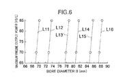
FIG. 6 is a graph showing a relationship between the bore diameter and a maximum engine output power. - With reference to the drawings, the present invention will now be described based on an embodiment thereof.
-
FIG. 1 is a schematic block diagram of an engine E (spark-ignition internal combustion engine) according to one embodiment of the present invention. This engine E is a four-cycle spark-ignition internal combustion engine adapted to be mounted on a vehicle such as an automobile. An engine body (internal combustion engine body) of the engine E comprises acylinder block 1 and acylinder head 2 placed on thecylinder block 1. A plurality of cylinders C are defined inside thecylinder block 1 and thecylinder head 2. While the number of the cylinders C is not particularly limited, it may be four, for example. Apiston 3 is fittingly inserted into each of the cylinders C in such a manner that it is slidably moved up and down inFIG. 1 along an axis c1 (seeFIG. 2 ) of the cylinder C. Thepiston 3 is connected to acrankshaft 4 rotatably supported by a lower portion of thecylinder block 1, through a connecting rod. A reciprocating movement of thepiston 3 is converted to a rotational movement of thecrankshaft 4. - Within the cylinder C, a
combustion chamber 5 is defined above thepiston 3.FIG. 2 is a schematic perspective view showing a structure around thecombustion chamber 5 of the engine body.FIG. 3 is a schematic sectional view showing a structure around thecombustion chamber 5 of the engine body when thepiston 3 is located at a top dead center position. Aceiling region 5a of thecombustion chamber 5 is defined by a depressed area of a lower surface of thecylinder head 2. In this embodiment, thecombustion chamber 5 is a so-called pentroof type which is formed in a triangular roof shape having an intake-side inclined surface and an exhaust-side inclined surface. - The
cylinder head 2 is formed with twointake ports 6 and twoexhaust ports 7 each communicating with thecombustion chamber 5. In this embodiment, theintake ports 6 are opened to the intake-side inclined surface defining theceiling region 5a of thecombustion chamber 5, and theexhaust ports 7 are opened to the exhaust-side inclined surface defining theceiling region 5a of thecombustion chamber 5. Thecylinder head 2 is provided with twointake valves 8 each adapted to shut off a respective one of theintake ports 6 from thecombustion chamber 5, and twoexhaust valves 9 each adapted to shut off a respective one of theexhaust ports 7 from thecombustion chamber 5. Each of theintake valves 8 and theexhaust valves 9 is adapted to be selectively opened and closed at a give timing by a non-illustrated valve-operating mechanism. - A
single spark plug 11 is installed in thecylinder head 2 in a posture extending along the axis c1 of the cylinder. In this state, a distal end of thespark plug 11 faces thecombustion chamber 5 from an approximately central position of theceiling region 5a of thecombustion chamber 5. Thespark plug 11 is adapted to generate a spark within thecombustion chamber 5 at a given timing to ignite an air-fuel mixture within thecombustion chamber 5, - An injector (fuel injection valve) 10 is installed in the
cylinder head 2 to directly inject fuel into thecombustion chamber 5. In this state, a distal end of theinjector 11 faces thecombustion chamber 5. More specifically, theinjector 10 is installed such that the distal end thereof is located below the twointake ports 6 and at an intermediate position between the twointake ports 6 in a horizontal direction. Theinjector 10 is adapted to inject fuel from an outer periphery toward a center of thecombustion chamber 5 at a given timing. Although the engine E according to this embodiment is designed while assuming a direct injection-type, the present invention can also be applied to a port injection-type engine. - A
top surface 3a of thepiston 3, i.e., a portion of thepiston 3 defining a floor region of thecombustion chamber 5, is formed with a raisedportion 31 which is raised from respective intake and exhaust sides toward a central region thereof in conformity to the triangular roof shape of theceiling region 5a of thecombustion chamber 5. The formation of the raisedportion 31 is useful in adjusting a volume of thecombustion chamber 5 to set a geometric compression ratio of the cylinder C to a high value. The formation of the raisedportion 31 is also desirable in terms of flame propagation characteristics, because a height of thecombustion chamber 5 is approximately equalized in its entirety. - A
concave portion 32 is formed in the raisedportion 31. Theconcave portion 32 is provided around a center of the raisedportion 3 and just below thespark plug 11. If a flame grown from an ignition point of thespark plug 11 prematurely collides with thetop surface 3a of thepiston 3, a flame growth rate becomes lower, which causes deterioration in flame propagation characteristics and therefore deterioration in engine thermal efficiency. In this regard, theconcave portion 32 provided in the engine E makes it possible to delay the collision between a flame grown from the ignition point of thespark plug 11 and thetop surface 3a of thepiston 3 to improve the flame propagation characteristics. It is understood that a specific shape of theconcave portion 32 is not limited to a bowl-like shape illustrated inFIG. 2 , - The number of the
spark plugs 11 to be provided per cylinder C may be two. In a two-point spark-ignition engine E where twospark plugs 11 are provided per cylinder C as above, one of thespark plugs 11 is installed approximately at a center of the ceiling .region 5a of thecombustion chamber 5 in the same manner as that in the aforementioned single-point spark-ignition engine E where only onespark plug 11 is provided per cylinder C, and theother spark plug 11 is installed approximately in an outer periphery of theceiling region 5a of thecombustion chamber 5, as shown inFIG. 4 . Further, twoconcave portions 32 are provided in the raisedportion 31 at positions corresponding to thespark plugs 11, - In the above engine E according to this embodiment, in order to provide enhanced engine thermal efficiency and improved fuel economy, a geometric compression ratio ε of the engine body is set to 14 or more. As is well known, the geometric compression ratio e is expressed as (V0 + V1) / V1, where V1 is a volume (total volume including a volume of the concave portion 32) of the
combustion chamber 5 when thepiston 3 is located at a top dead center (TDC) position, and V0 is an engine displacement (stroke volume). - In this embodiment, on the assumption that the geometric compression ratio e of the engine body is set to 14.0, a stroke length S of the
piston 3 is set to 81.2 mm or more, in order to ensure an output torque in a low-speed/high-load operation region. Further, in order to allow a maximum output power of the engine E to become 70 PS /L or more, the stroke length S of thepiston 3 is set to satisfy the following relationship: S ≤ 0,977 × B + 18.2, where B is a bore diameter of the cylinder C. Specifically, in the graph illustrated inFIG. 5 which represents a relationship between the bore diameter B and the stroke length S, the stroke length S and the bore diameter B are set in the region A between by the line Lb_14 on which the stroke length S is 81.2 mm, and the line La_70 on which the stroke length S is "0.977 × B + 18.2". - In
FIG. 5 , each of the dashed lines L1 to L6 is a constant-displacement line which represents a relationship between the stroke length S and the bore diameter B in an engine body having a certain engine displacement. Specifically, values of the stroke length S and the bore diameter B providing engine displacements of 1.3 litter, 1.5 litter, 1.8 litter, 2.0 litter, 2.3 litter and 2.5 litter, are plotted on L1, L2, L3, L4, L5 and L6, respectively. - Thus, in this embodiment, each of the stroke length S of the
piston 3 and the bore diameter B of the cylinder C is set to a value on a line segment located within the region A in one of the constant-displacement lines L1 to L6 corresponding to a required engine displacement of the engine body. - The stroke length S is set to satisfy the above conditions, based on the following research results.
- Firstly, a result of a research on the condition "S ≤ 0.977 × B + 18.2" will be described.
- As mentioned above, if a flame grown from the ignition point of the
spark plug 11 prematurely collides with thetop surface 3a of thepiston 3, engine thermal efficiency will deteriorate. Thus, it is desirable that a clearance between thespark plug 11 and thetop surface 3a of thepiston 3, i.e., a height of thecombustion chamber 5, is increased to some extent. For this reason, as a prerequisite to setting the geometric compression ratio e of the engine body to a higher value, it is necessary to increase the stroke length S of thepiston 3. However, as shown by each of the contact-displacement lines inFIG. 5 , as the stroke length S of thepiston 3 is increased, the bore diameter B of the cylinder C becomes relatively smaller. If the bore diameter B becomes smaller, a diameter of each of theintake valves 8 becomes smaller, and thereby an opening area of theintake valve 8 becomes smaller. This is liable to cause failing to charge a sufficient amount of intake air into thecylinder 11 during an increase in engine speed, resulting in lowering of engine output power. - Therefore, the inventers checked an influence of the bore diameter B and the diameter of the
intake valve 8, on the engine output power, under a constant engine displacement. Specifically, a plurality of types of engines were prepared to have the same engine displacement and become different from each other in the bore diameter B of the cylinder C and therefore in size of the ceiling region of thecombustion chamber 5 and the diameter of theintake valve 8, and then a maximum engine output power of each of the engines was measured. This measurement was performed for a plurality of engines each having a different engine displacement, specifically, a plurality of engines having engine displacements of 1.3 litter, 1.5 litter, 1.8 litter, 2.0 litter, 2.3 litter and 2.5 litter, respectively. A result of the measurement is shown inFIG. 6 . As shown inFIG. 6 , as the bore diameter B of the cylinder C becomes larger and thereby the diameter of theintake valve 8 becomes lager, the maximum engine output power becomes higher, InFIG. 6 , the lines L11, L12, L13, L14, L15 and L16 are respective measurement results in the engines having the engine displacements of 1.3 litter, 1.5 litter, 1.8 litter, 2.0 litter, 2.3 litter and 2.5 litter, wherein an engine speed at a maximum engine output power of 70 PS/L is 6500 rpm, and an engines speed at a maximum engine output power of 85 PS/L is 7000 rpm. - The bore diameter B achieving a maximum engine output power of 70 PS/L (hereinafter referred to as "70 PS/L bore diameter") in each of the engine displacements, and the stroke length S corresponding to the 70 PS/L bore diameter, were plotted on the graph in
FIG. 5 (points P1 to P6). As a result, it was found that the 70 PS/L bore diameter and the stroke length Shave the following relationship: S = 0.977 × B + 18.2, irrespective of engine displacement. This means that a maximum engine output power of 70 PS/L or more can be ensured by setting the bore diameter B to a value greater than the 70 PS/L bore diameter, i.e., setting the stroke length S to a value equal to or less than a linear function of the bore diameter B: 0.977 × B + 18.2. - Further, the bore diameter B achieving a maximum engine output power of 85 PS/L (hereinafter referred to as "85 PS/L bore diameter") in each of the engine displacements, and the stroke length S corresponding to the 85 PS/L bore diameter, were plotted on the graph in
FIG. 5 (points P11 to P16). As a result, it was found that the 85 PS/L bore diameter and the stroke length S have the following relationship: S = 0.977 × B + 15.1 (straight line La_85 inFIG. 5 ), irrespective of engine displacement. This means that a maximum engine output power of 85 PS/L or more can be ensured by setting the bore diameter B to a value greater than the 85 PS/L bore diameter, i.e., setting the stroke length S to a value equal to or less than a linear function of the bore diameter B: 0.977 × B + 15.1. - A result of a research on the condition "S≥81.2" will be described below.
- As mentioned above, as a prerequisite to increasing the geometric compression ratio ε of the engine body while ensuring a given level of height of the
combustion chamber 5, it is necessary to increase the stroke length S of thepiston 3 to some extent. In this regard, the inventers found that a lower limit value of the stroke length S is determined by a requirement of ensuring an output torque in a low-load operation region, in addition to the aforementioned requirement of avoiding the premature collision between a flame and thetop surface 3a of thepiston 3. - In a low-speed and high-load operating region of the engine body, it is necessary to open the
intake valves 8 and theexhaust valves 9 to scavenge an inside of the cylinder C so as to sufficiently introduce fresh air into the cylinder C and reduce an internal temperature of the cylinder C to avoid the occurrence of knocking. In this regard, the inventers carried out a test using a plurality of types of engines. As a result, it was proven that, as a prerequisite to obtain an output torque of 100 Nm or more per 1000 cc engine displacement at 2000 rpm, it is necessary to set a valve overlap period where all of theintake valves 8 and theexhaust valves 9 are overlappingly opened, to 35 degrees in crank angle (CA) across top dead center. In cases where the valve overlap period is set to 35 degrees in CA across top dead center, each of theintake valves 8 and theexhaust valves 9 comes closest to thepiston 3 around BTDC (before top dead center) 9-degree CA and ATDC (after top dead center) 8-degree CA. As a prerequisite to avoiding collision between each of the intake andexhaust valves piston 3, it is necessary to set a distance between thetop surface 3a of thepiston 3 located at a top dead center position and a lower surface (8a, 9a) of each of the intake andexhaust valves exhaust valves - In order to facilitate understanding of the relational expression regarding the bore diameter and the stroke length, the relational expression was simplified and modeled as follows. A volume V1 of the
combustion chamber 5 is expressed as V1 = A × h × K1 + (A - K2) × K3, where: A is a cross-sectional area of the cylinder (A = engine displacement per cylinder C V0 / stroke length S); h is a distance between thetop surface 3a of thepiston 3 and the lower surface (8a, 9a) of each of the intake andexhaust valves exhaust valves top surface 3a of thepiston 3; K1 is a constant to be determined depending on a shape of thecombustion chamber 5; (A - K2 ) × K3 is a volume of a gap between each of the intake andexhaust valves cylinder head 2; K2 is a sum of respective valve areas of the intake andexhaust valves combustion chamber 5 to "(ε - 1)× V0'' or less. This expression is converted as follows by assigning the above formula regarding V1 thereto: h ≤ (V0 / (ε- 1) - (A - K2)) × K3) /AK1. As a prerequisite to obtaining a height h of 5 mm or more as mentioned above, it is necessary to satisfy at least the following relationship: (V0 / (e- 1) - (A - K2)) × K3) /AK1 ≥ 5. Based on this expression, a requirement to allow the distance between thetop surface 3a of thepiston 3 and the lower surface (8a, 9a) of each of the intake andexhaust valves FIG. 5 is a line on which the stroke length S is 84.75 mm. - Based on the above research results, in the single-point spark-ignition engine, the stroke length S can be set in the region A in
FIG. 5 , i.e., the region between by the straight line La_70 and the straight line Lib_14. This makes it possible to ensure the output torque in the low-speed/high-load operation region while setting the geometric compression ratio to 14 or more, This also makes it possible to achieve a maximum engine output power of 70 PS/L (at 6500 rpm) and ensure the valve overlap period while avoiding the collision between thepiston 3 and each of the intake andexhaust valves - In this case, as is well known, it is preferable that an average piston velocity of the
piston 3 is set to a given value or less, e.g., 22 m/ s or less, in view of durability of thepiston 3. For this reason, it is preferable that the stroke length S is set to a value allowing the average piston velocity to become 22 m/s or less, while taking into account the linear function of the bore diameter B. Specifically, it is preferable to set the stroke length S to 100.4 mm or less when the engine speed is 6500 rpm. it is also preferable to set the stroke length S to 94.6 mm or less when the engine speed is 7000 rpm. More specifically, it is preferable that the stroke length S is set in a region below the straight line Lc_65 inFIG. 5 on which the stroke length S is 100.4 mm, or in a region below the straight line Lc_70 inFIG. 5 on which the stroke length S is 94.6 mm. - It is understood that the spark-ignition internal combustion engine of the present invention is not limited to the type in the above embodiment, but the present invention may be applied to any other suitable type of spark-ignition internal combustion engine. For example, the engine E may be any multi-cylinder engine other than a four-cylinder engine, such as a six-cylinder engine.
- As above, the inventers made various researches on the relationship between respective ones of a stroke length S, a bore diameter B and engine output power by variously changing the stroke length S, the bore diameter B and a diameter of an intake valve in various engine displacements. As a result, the inventers found that a given value or more of the engine output power can be obtained if the stroke length S and the bore diameter B satisfy a certain relationship. Further, in the course of the researches, the inventers found that, as a prerequisite to ensuring a sufficient amount of flesh air in a cylinder C and reducing residual gas in the cylinder C to reduce an internal temperature of the cylinder C, in a low-speed/high-load operation region, it is necessary to provide a valve overlap period where all of two
intake valves 6 and twoexhaust valves 8 are overlappingly opened, to ensure a given scavenging capability, and, as a prerequisite to achieving this valve overlap, it is necessary to set a clearance between a lower surface (8a, 9a) of each of the intake andexhaust valves top surface 3a of apiston 3, to a given value or more. - Based on the above research findings, the present invention provides a spark-ignition internal combustion engine which comprises: an engine body including a cylinder, a piston adapted to be reciprocatingly moved within the cylinder, and a cylinder head provided on the cylinder to define a combustion chamber in cooperation with a top surface of the piston; two intake valves provided in the cylinder head and each capable of shutting off an inflow of air into the cylinder; two exhaust valves provided in the cylinder head and each capable of shutting off an outflow of exhaust gas from the cylinder; a spark plug provided in the cylinder head to face the combustion chamber; and a fuel injection valve provided in the cylinder head to face the combustion chamber, wherein: a geometric compression ratio of the engine body is set to 14 or more; each of a clearance between the top surface of the piston located at a top dead center position and a lower surface of each of the intake valves in a full-closed state, and a clearance between the top surface of the piston located at the top dead center position and a lower surface of each of the exhaust valves in a fall-closed state, is set to 5 mm or more; and a stroke length S of the piston is set to satisfy the following relationship: S ≤ 0.977 × B + 18.2, where B is a bore diameter of the cylinder.
- The spark-ignition internal combustion engine of the present invention makes it possible to achieve high engine output power while setting the geometric compression ratio of the engine body to 14 or more to achieve high thermal efficiency and therefore high fuel economy performance.
- Specifically, the stroke length S and the bore diameter B are set to satisfy the following relationship: S ≤ 0.977 × B + 18.2, to allow the bore diameter B to have a sufficient size, so that it becomes possible to ensure an opening area of the intake valve to ensure a cylinder air charge amount during a high-speed operation, while setting the geometric compression ratio of the engine body to a high value. The high geometric compression ratio contributes to achievement of high fuel economy performance, and the ensuring of the cylinder air charge amount contributes to achievement of high engine output power. In the present invention, the above expression is designed to ensure an engine output power of 70 PS or more per unit engine displacement. Thus, at least an engine output power of 70 PS/L can be obtained by satisfying the above expression.
- In addition, the clearance between the lower surface of each of the intake and exhaust valves and the top surface of the piston is set to 5 mm or more, so that it becomes possible to simultaneously open the intake valves and the exhaust valves in a given lift amount around top dead center. This means that a scavenging capability is improved by the valve overlap. The improvement in the scavenging capability, i.e., a reduction in residual gas, makes it possible to reduce an internal temperature of the cylinder to allow an ignition timing to be controllably advanced, and increase an amount of fresh air in the cylinder to increase an output torque.
- The stroke length S and the bore diameter B may be set to satisfy the following relationship: S ≤ 0.977 × B + 15.1, to ensure an engine output power of 85 PS/L, or more.
- Under a condition that the geometric compression ratio is 14 or more, a requirement to allow each of a clearance between the top surface of the piston located at a top dead center position and a lower surface of each of the intake valves in a full-closed state, and a clearance between the top surface of the piston located at the top dead center position and a lower surface of each of the exhaust valves in a full-closed state, to become 5 mm or more, is calculated as 81.2 mem. Thus, preferably, in the present invention, the stroke length S of the piston is set to 81.2 mm or more,
- This makes it possible to ensure the valve overlap period around top dead center while setting the geometric compression ratio of the engine body to 14 or more.
- In the present invention, under a condition that the geometric compression ratio is 15 or more, a requirement to allow each of a clearance between the top surface of the piston located at a top dead center position and a lower surface of each of the intake valves in a full-closed state, and a clearance between the top surface of the piston located at the top dead center position and a lower surface of each of the exhaust valves in a full-closed state, to become 5 mm or more, is calculated as S = 84.75 mm. Thus, preferably, in the present invention, the stroke length S of the piston is set to 84.75 mm or more.
- This makes it possible to ensure the valve overlap period around top dead center while setting the geometric compression ratio of the engine body to 15 or more.
- This application is based on Japanese Patent Application No.
2009-243571 - Although the present invention has been fully described by way of example with reference to the accompanying drawings, it is to be understood that various changes and modifications will be apparent to those skilled in the art. Therefore, unless otherwise such changes and modifications depart from the scope of the present invention hereinafter defined, they should be construed as being included therein.
Claims (4)
- A spark-ignition internal combustion engine comprising:an engine body including a cylinder (C), a piston (3) adapted to be reciprocatingly moved within the cylinder (C), and a cylinder head (2) provided on the cylinder (C) to define a combustion chamber (5) in cooperation with a top surface (3a) of the piston (3);two intake valves (8) provided in the cylinder head (2) and each capable of shutting off an inflow of air into the cylinder (C);two exhaust valves (9) provided in the cylinder head (2) and each capable of shutting off an outflow of exhaust gas from the cylinder (C);a spark plug (11) provided in the cylinder head (2) to face the combustion chamber (5); anda fuel injection valve (10) provided in the cylinder head (2) to face the combustion chamber (5),characterized in that:a geometric compression ratio of the engine body is set to 14 or more;each of a clearance between the top surface (3a) of the piston (3) located at a top dead center position and a lower surface (8a) of each of the intake valves (8) in a full-closed state, and a clearance between the top surface (3a) of the piston (3) located at the top dead center position and a lower surface (9a) of each of the exhaust valves (9) in a full-closed state, is set to 5 mm or more; anda stroke length S of the piston (3) is set to satisfy the following relationship: S ≤ 0.977 × B + 18.2, where B is a bore diameter of the cylinder (C).
- The spark-ignition internal combustion engine as defined in claim 1, characterized in that the stroke length S of the piston (3) is set to satisfy the following relationship: S ≤ 0.977 × B + 15.1; where B is a bore diameter of the cylinder (C).
- The spark-ignition internal combustion engine as defined in claim 1 or 2, characterized in that the stroke length S of the piston (3) is set to 81.2 mm or more.
- The spark-ignition internal combustion engine as defined in claim 1 or 2, characterized in that the stroke length S of the piston (3) is set to 84.75 mm or more.
Applications Claiming Priority (1)
| Application Number | Priority Date | Filing Date | Title |
|---|---|---|---|
| JP2009243571A JP2011089472A (en) | 2009-10-22 | 2009-10-22 | Spark ignition type internal combustion engine |
Publications (3)
| Publication Number | Publication Date |
|---|---|
| EP2314841A2 true EP2314841A2 (en) | 2011-04-27 |
| EP2314841A3 EP2314841A3 (en) | 2011-10-26 |
| EP2314841B1 EP2314841B1 (en) | 2013-03-06 |
Family
ID=43662334
Family Applications (1)
| Application Number | Title | Priority Date | Filing Date |
|---|---|---|---|
| EP10188314A Active EP2314841B1 (en) | 2009-10-22 | 2010-10-21 | Spark-ignition internal combustion engine |
Country Status (4)
| Country | Link |
|---|---|
| US (1) | US8820292B2 (en) |
| EP (1) | EP2314841B1 (en) |
| JP (1) | JP2011089472A (en) |
| CN (2) | CN201884116U (en) |
Cited By (1)
| Publication number | Priority date | Publication date | Assignee | Title |
|---|---|---|---|---|
| CN102536498A (en) * | 2012-03-15 | 2012-07-04 | 重庆长安汽车股份有限公司 | Cylinder cover for direct injection gasoline engine |
Families Citing this family (7)
| Publication number | Priority date | Publication date | Assignee | Title |
|---|---|---|---|---|
| JP2011089472A (en) * | 2009-10-22 | 2011-05-06 | Mazda Motor Corp | Spark ignition type internal combustion engine |
| US9322339B2 (en) * | 2012-01-19 | 2016-04-26 | International Engine Intellectual Property Company, Llc. | Internal combustion engine operating on different reactivity fuels |
| CN105722964A (en) * | 2013-11-25 | 2016-06-29 | 出光兴产株式会社 | Lubricating oil composition for spark ignition internal combustion engine |
| JP2014074413A (en) * | 2014-01-20 | 2014-04-24 | Mazda Motor Corp | Spark ignition type internal combustion engine |
| JP6060126B2 (en) * | 2014-10-22 | 2017-01-11 | 本田技研工業株式会社 | Internal combustion engine |
| JP6508238B2 (en) * | 2017-03-27 | 2019-05-08 | マツダ株式会社 | Spark-ignition type internal combustion engine |
| CN108071498A (en) * | 2017-11-10 | 2018-05-25 | 任军 | A kind of internal combustion engine for becoming geometrical compression ratio |
Citations (2)
| Publication number | Priority date | Publication date | Assignee | Title |
|---|---|---|---|---|
| JP2007154827A (en) | 2005-12-07 | 2007-06-21 | Toyota Motor Corp | Combustion control device for internal combustion engine |
| JP2009243571A (en) | 2008-03-31 | 2009-10-22 | Aisin Aw Co Ltd | Power transmission device |
Family Cites Families (21)
| Publication number | Priority date | Publication date | Assignee | Title |
|---|---|---|---|---|
| GB2070135B (en) * | 1980-02-12 | 1984-02-01 | Nissan Motor | Spark-ignition internal combustion engine |
| JPS58180719A (en) * | 1982-04-17 | 1983-10-22 | Honda Motor Co Ltd | Torch ignition type gasoline internal-combustion engine |
| JPS6185516A (en) | 1984-10-02 | 1986-05-01 | Hino Motors Ltd | Variable valve timing mechanism |
| JP2820946B2 (en) | 1989-02-17 | 1998-11-05 | マツダ株式会社 | Engine combustion chamber structure |
| DE4232044C2 (en) * | 1991-09-26 | 1998-01-29 | Mazda Motor | Internal combustion engine with spark ignition |
| JP3047789B2 (en) * | 1995-05-16 | 2000-06-05 | 三菱自動車工業株式会社 | In-cylinder injection internal combustion engine and piston for in-cylinder injection internal combustion engine |
| KR970703480A (en) | 1995-03-28 | 1997-07-03 | 츠카하라 시게히사 | Internal injection type internal combustion engine |
| JP2000248945A (en) * | 1999-03-02 | 2000-09-12 | Suzuki Motor Corp | Cylinder direct injection engine |
| US6553959B2 (en) * | 2000-06-13 | 2003-04-29 | Visteon Global Technologies, Inc. | Electronic flow control for a stratified EGR system |
| JP3979081B2 (en) | 2001-01-16 | 2007-09-19 | 日産自動車株式会社 | Combustion control system for internal combustion engine |
| JP2003056351A (en) * | 2001-08-08 | 2003-02-26 | Toyota Motor Corp | Cylinder injection type spark ignition internal combustion engine |
| JP2003214297A (en) | 2002-01-24 | 2003-07-30 | Yanmar Co Ltd | Fuel injection valve of diesel engine |
| US6588396B1 (en) * | 2002-02-01 | 2003-07-08 | General Motors Corporation | Spark ignition direct injection engine with oval fuel spray into oblong piston bowl |
| JP2003239836A (en) * | 2002-02-15 | 2003-08-27 | Osaka Gas Co Ltd | Engine and operation control device of the same |
| JP4475221B2 (en) * | 2005-03-11 | 2010-06-09 | トヨタ自動車株式会社 | engine |
| JP2007009768A (en) | 2005-06-29 | 2007-01-18 | Toyota Motor Corp | Controller of spark-ignition direct injection internal combustion engine |
| EP1764491B1 (en) * | 2005-09-15 | 2009-12-09 | Mazda Motor Corporation | Combustion chamber structure for spark-ignition engine |
| US7484498B2 (en) * | 2006-03-31 | 2009-02-03 | Mazda Motor Corporation | Spark-ignition gasoline engine |
| JP2009024626A (en) * | 2007-07-20 | 2009-02-05 | Toyota Motor Corp | Cylinder-injection spark-ignition internal combustion engine |
| JP5003496B2 (en) * | 2008-01-08 | 2012-08-15 | マツダ株式会社 | Reciprocating engine |
| JP2011089472A (en) * | 2009-10-22 | 2011-05-06 | Mazda Motor Corp | Spark ignition type internal combustion engine |
-
2009
- 2009-10-22 JP JP2009243571A patent/JP2011089472A/en active Pending
-
2010
- 2010-10-19 US US12/907,394 patent/US8820292B2/en active Active
- 2010-10-21 EP EP10188314A patent/EP2314841B1/en active Active
- 2010-10-22 CN CN2010205954649U patent/CN201884116U/en not_active Expired - Fee Related
- 2010-10-22 CN CN201010534054.8A patent/CN102042074B/en active Active
Patent Citations (2)
| Publication number | Priority date | Publication date | Assignee | Title |
|---|---|---|---|---|
| JP2007154827A (en) | 2005-12-07 | 2007-06-21 | Toyota Motor Corp | Combustion control device for internal combustion engine |
| JP2009243571A (en) | 2008-03-31 | 2009-10-22 | Aisin Aw Co Ltd | Power transmission device |
Cited By (1)
| Publication number | Priority date | Publication date | Assignee | Title |
|---|---|---|---|---|
| CN102536498A (en) * | 2012-03-15 | 2012-07-04 | 重庆长安汽车股份有限公司 | Cylinder cover for direct injection gasoline engine |
Also Published As
| Publication number | Publication date |
|---|---|
| JP2011089472A (en) | 2011-05-06 |
| US8820292B2 (en) | 2014-09-02 |
| EP2314841B1 (en) | 2013-03-06 |
| EP2314841A3 (en) | 2011-10-26 |
| CN102042074B (en) | 2015-10-07 |
| CN102042074A (en) | 2011-05-04 |
| CN201884116U (en) | 2011-06-29 |
| US20110094473A1 (en) | 2011-04-28 |
Similar Documents
| Publication | Publication Date | Title |
|---|---|---|
| EP2314841B1 (en) | Spark-ignition internal combustion engine | |
| EP1857654B1 (en) | Inernal combustion engine | |
| US9470174B2 (en) | Control system and control method of spark ignition gasoline engine | |
| JP5998751B2 (en) | Spark ignition direct injection engine | |
| JPH0559948A (en) | Engine with supercharger | |
| JP2007211730A (en) | Reciprocating internal combustion engine | |
| US9062598B2 (en) | Internal combustion engine operable in homogeneous-charge compression mode | |
| CN109098844B (en) | Variable compression ratio engine | |
| JP4702409B2 (en) | Spark ignition internal combustion engine | |
| JP5831169B2 (en) | Control device for spark ignition gasoline engine | |
| JP4442542B2 (en) | Reciprocating piston type engine | |
| JP6128091B2 (en) | Diesel engine and manufacturing method thereof | |
| JP2012041846A (en) | Method for controlling fuel injection and ignition timing of internal combustion engine | |
| EP4043711A1 (en) | Internal combustion engine, vehicle | |
| JP5618020B2 (en) | Spark ignition internal combustion engine | |
| JP5618021B2 (en) | Spark ignition internal combustion engine | |
| JP6369692B2 (en) | Engine abnormal combustion detection device and engine control device | |
| JP5618019B2 (en) | Spark ignition internal combustion engine | |
| JP5494849B2 (en) | Method for manufacturing spark ignition internal combustion engine | |
| KR20210126745A (en) | How to mitigate pre-ignition in an internal combustion engine | |
| JP2006257999A (en) | Internal combustion engine | |
| JP2013213486A (en) | Structure of internal combustion engine with unprecedented high efficiency | |
| JP5962084B2 (en) | Control device for spark ignition gasoline engine | |
| JP7380150B2 (en) | engine control device | |
| EP0035525A1 (en) | Intake gas recirculation |
Legal Events
| Date | Code | Title | Description |
|---|---|---|---|
| PUAI | Public reference made under article 153(3) epc to a published international application that has entered the european phase |
Free format text: ORIGINAL CODE: 0009012 |
|
| AK | Designated contracting states |
Kind code of ref document: A2 Designated state(s): AL AT BE BG CH CY CZ DE DK EE ES FI FR GB GR HR HU IE IS IT LI LT LU LV MC MK MT NL NO PL PT RO RS SE SI SK SM TR |
|
| AX | Request for extension of the european patent |
Extension state: BA ME |
|
| PUAL | Search report despatched |
Free format text: ORIGINAL CODE: 0009013 |
|
| RIC1 | Information provided on ipc code assigned before grant |
Ipc: F02B 23/10 20060101AFI20110914BHEP |
|
| AK | Designated contracting states |
Kind code of ref document: A3 Designated state(s): AL AT BE BG CH CY CZ DE DK EE ES FI FR GB GR HR HU IE IS IT LI LT LU LV MC MK MT NL NO PL PT RO RS SE SI SK SM TR |
|
| AX | Request for extension of the european patent |
Extension state: BA ME |
|
| 17P | Request for examination filed |
Effective date: 20120426 |
|
| GRAP | Despatch of communication of intention to grant a patent |
Free format text: ORIGINAL CODE: EPIDOSNIGR1 |
|
| GRAS | Grant fee paid |
Free format text: ORIGINAL CODE: EPIDOSNIGR3 |
|
| GRAA | (expected) grant |
Free format text: ORIGINAL CODE: 0009210 |
|
| AK | Designated contracting states |
Kind code of ref document: B1 Designated state(s): AL AT BE BG CH CY CZ DE DK EE ES FI FR GB GR HR HU IE IS IT LI LT LU LV MC MK MT NL NO PL PT RO RS SE SI SK SM TR |
|
| REG | Reference to a national code |
Ref country code: GB Ref legal event code: FG4D |
|
| REG | Reference to a national code |
Ref country code: CH Ref legal event code: EP Ref country code: AT Ref legal event code: REF Ref document number: 599754 Country of ref document: AT Kind code of ref document: T Effective date: 20130315 |
|
| REG | Reference to a national code |
Ref country code: IE Ref legal event code: FG4D |
|
| REG | Reference to a national code |
Ref country code: DE Ref legal event code: R096 Ref document number: 602010005227 Country of ref document: DE Effective date: 20130502 |
|
| REG | Reference to a national code |
Ref country code: DE Ref legal event code: R084 Ref document number: 602010005227 Country of ref document: DE |
|
| REG | Reference to a national code |
Ref country code: AT Ref legal event code: MK05 Ref document number: 599754 Country of ref document: AT Kind code of ref document: T Effective date: 20130306 |
|
| PG25 | Lapsed in a contracting state [announced via postgrant information from national office to epo] |
Ref country code: NO Free format text: LAPSE BECAUSE OF FAILURE TO SUBMIT A TRANSLATION OF THE DESCRIPTION OR TO PAY THE FEE WITHIN THE PRESCRIBED TIME-LIMIT Effective date: 20130606 Ref country code: BG Free format text: LAPSE BECAUSE OF FAILURE TO SUBMIT A TRANSLATION OF THE DESCRIPTION OR TO PAY THE FEE WITHIN THE PRESCRIBED TIME-LIMIT Effective date: 20130606 Ref country code: AT Free format text: LAPSE BECAUSE OF FAILURE TO SUBMIT A TRANSLATION OF THE DESCRIPTION OR TO PAY THE FEE WITHIN THE PRESCRIBED TIME-LIMIT Effective date: 20130306 Ref country code: LT Free format text: LAPSE BECAUSE OF FAILURE TO SUBMIT A TRANSLATION OF THE DESCRIPTION OR TO PAY THE FEE WITHIN THE PRESCRIBED TIME-LIMIT Effective date: 20130306 Ref country code: ES Free format text: LAPSE BECAUSE OF FAILURE TO SUBMIT A TRANSLATION OF THE DESCRIPTION OR TO PAY THE FEE WITHIN THE PRESCRIBED TIME-LIMIT Effective date: 20130617 Ref country code: SE Free format text: LAPSE BECAUSE OF FAILURE TO SUBMIT A TRANSLATION OF THE DESCRIPTION OR TO PAY THE FEE WITHIN THE PRESCRIBED TIME-LIMIT Effective date: 20130306 |
|
| REG | Reference to a national code |
Ref country code: NL Ref legal event code: VDEP Effective date: 20130306 |
|
| REG | Reference to a national code |
Ref country code: DE Ref legal event code: R084 Ref document number: 602010005227 Country of ref document: DE Effective date: 20130621 |
|
| REG | Reference to a national code |
Ref country code: LT Ref legal event code: MG4D |
|
| PG25 | Lapsed in a contracting state [announced via postgrant information from national office to epo] |
Ref country code: LV Free format text: LAPSE BECAUSE OF FAILURE TO SUBMIT A TRANSLATION OF THE DESCRIPTION OR TO PAY THE FEE WITHIN THE PRESCRIBED TIME-LIMIT Effective date: 20130306 Ref country code: GR Free format text: LAPSE BECAUSE OF FAILURE TO SUBMIT A TRANSLATION OF THE DESCRIPTION OR TO PAY THE FEE WITHIN THE PRESCRIBED TIME-LIMIT Effective date: 20130607 Ref country code: FI Free format text: LAPSE BECAUSE OF FAILURE TO SUBMIT A TRANSLATION OF THE DESCRIPTION OR TO PAY THE FEE WITHIN THE PRESCRIBED TIME-LIMIT Effective date: 20130306 Ref country code: SI Free format text: LAPSE BECAUSE OF FAILURE TO SUBMIT A TRANSLATION OF THE DESCRIPTION OR TO PAY THE FEE WITHIN THE PRESCRIBED TIME-LIMIT Effective date: 20130306 |
|
| PG25 | Lapsed in a contracting state [announced via postgrant information from national office to epo] |
Ref country code: RS Free format text: LAPSE BECAUSE OF FAILURE TO SUBMIT A TRANSLATION OF THE DESCRIPTION OR TO PAY THE FEE WITHIN THE PRESCRIBED TIME-LIMIT Effective date: 20130306 Ref country code: BE Free format text: LAPSE BECAUSE OF FAILURE TO SUBMIT A TRANSLATION OF THE DESCRIPTION OR TO PAY THE FEE WITHIN THE PRESCRIBED TIME-LIMIT Effective date: 20130306 Ref country code: HR Free format text: LAPSE BECAUSE OF FAILURE TO SUBMIT A TRANSLATION OF THE DESCRIPTION OR TO PAY THE FEE WITHIN THE PRESCRIBED TIME-LIMIT Effective date: 20130306 |
|
| PG25 | Lapsed in a contracting state [announced via postgrant information from national office to epo] |
Ref country code: IS Free format text: LAPSE BECAUSE OF FAILURE TO SUBMIT A TRANSLATION OF THE DESCRIPTION OR TO PAY THE FEE WITHIN THE PRESCRIBED TIME-LIMIT Effective date: 20130706 Ref country code: SK Free format text: LAPSE BECAUSE OF FAILURE TO SUBMIT A TRANSLATION OF THE DESCRIPTION OR TO PAY THE FEE WITHIN THE PRESCRIBED TIME-LIMIT Effective date: 20130306 Ref country code: NL Free format text: LAPSE BECAUSE OF FAILURE TO SUBMIT A TRANSLATION OF THE DESCRIPTION OR TO PAY THE FEE WITHIN THE PRESCRIBED TIME-LIMIT Effective date: 20130306 Ref country code: EE Free format text: LAPSE BECAUSE OF FAILURE TO SUBMIT A TRANSLATION OF THE DESCRIPTION OR TO PAY THE FEE WITHIN THE PRESCRIBED TIME-LIMIT Effective date: 20130306 Ref country code: PT Free format text: LAPSE BECAUSE OF FAILURE TO SUBMIT A TRANSLATION OF THE DESCRIPTION OR TO PAY THE FEE WITHIN THE PRESCRIBED TIME-LIMIT Effective date: 20130708 Ref country code: CZ Free format text: LAPSE BECAUSE OF FAILURE TO SUBMIT A TRANSLATION OF THE DESCRIPTION OR TO PAY THE FEE WITHIN THE PRESCRIBED TIME-LIMIT Effective date: 20130306 Ref country code: RO Free format text: LAPSE BECAUSE OF FAILURE TO SUBMIT A TRANSLATION OF THE DESCRIPTION OR TO PAY THE FEE WITHIN THE PRESCRIBED TIME-LIMIT Effective date: 20130306 |
|
| PG25 | Lapsed in a contracting state [announced via postgrant information from national office to epo] |
Ref country code: PL Free format text: LAPSE BECAUSE OF FAILURE TO SUBMIT A TRANSLATION OF THE DESCRIPTION OR TO PAY THE FEE WITHIN THE PRESCRIBED TIME-LIMIT Effective date: 20130306 |
|
| PLBE | No opposition filed within time limit |
Free format text: ORIGINAL CODE: 0009261 |
|
| STAA | Information on the status of an ep patent application or granted ep patent |
Free format text: STATUS: NO OPPOSITION FILED WITHIN TIME LIMIT |
|
| PG25 | Lapsed in a contracting state [announced via postgrant information from national office to epo] |
Ref country code: DK Free format text: LAPSE BECAUSE OF FAILURE TO SUBMIT A TRANSLATION OF THE DESCRIPTION OR TO PAY THE FEE WITHIN THE PRESCRIBED TIME-LIMIT Effective date: 20130306 |
|
| 26N | No opposition filed |
Effective date: 20131209 |
|
| PG25 | Lapsed in a contracting state [announced via postgrant information from national office to epo] |
Ref country code: IT Free format text: LAPSE BECAUSE OF FAILURE TO SUBMIT A TRANSLATION OF THE DESCRIPTION OR TO PAY THE FEE WITHIN THE PRESCRIBED TIME-LIMIT Effective date: 20130306 |
|
| REG | Reference to a national code |
Ref country code: DE Ref legal event code: R097 Ref document number: 602010005227 Country of ref document: DE Effective date: 20131209 |
|
| PG25 | Lapsed in a contracting state [announced via postgrant information from national office to epo] |
Ref country code: MC Free format text: LAPSE BECAUSE OF FAILURE TO SUBMIT A TRANSLATION OF THE DESCRIPTION OR TO PAY THE FEE WITHIN THE PRESCRIBED TIME-LIMIT Effective date: 20130306 |
|
| REG | Reference to a national code |
Ref country code: IE Ref legal event code: MM4A |
|
| REG | Reference to a national code |
Ref country code: FR Ref legal event code: ST Effective date: 20140630 |
|
| PG25 | Lapsed in a contracting state [announced via postgrant information from national office to epo] |
Ref country code: FR Free format text: LAPSE BECAUSE OF NON-PAYMENT OF DUE FEES Effective date: 20131031 |
|
| PG25 | Lapsed in a contracting state [announced via postgrant information from national office to epo] |
Ref country code: IE Free format text: LAPSE BECAUSE OF NON-PAYMENT OF DUE FEES Effective date: 20131021 |
|
| PG25 | Lapsed in a contracting state [announced via postgrant information from national office to epo] |
Ref country code: SM Free format text: LAPSE BECAUSE OF FAILURE TO SUBMIT A TRANSLATION OF THE DESCRIPTION OR TO PAY THE FEE WITHIN THE PRESCRIBED TIME-LIMIT Effective date: 20130306 |
|
| REG | Reference to a national code |
Ref country code: CH Ref legal event code: PL |
|
| GBPC | Gb: european patent ceased through non-payment of renewal fee |
Effective date: 20141021 |
|
| PG25 | Lapsed in a contracting state [announced via postgrant information from national office to epo] |
Ref country code: TR Free format text: LAPSE BECAUSE OF FAILURE TO SUBMIT A TRANSLATION OF THE DESCRIPTION OR TO PAY THE FEE WITHIN THE PRESCRIBED TIME-LIMIT Effective date: 20130306 Ref country code: CY Free format text: LAPSE BECAUSE OF FAILURE TO SUBMIT A TRANSLATION OF THE DESCRIPTION OR TO PAY THE FEE WITHIN THE PRESCRIBED TIME-LIMIT Effective date: 20130306 |
|
| PG25 | Lapsed in a contracting state [announced via postgrant information from national office to epo] |
Ref country code: LU Free format text: LAPSE BECAUSE OF NON-PAYMENT OF DUE FEES Effective date: 20131021 Ref country code: HU Free format text: LAPSE BECAUSE OF FAILURE TO SUBMIT A TRANSLATION OF THE DESCRIPTION OR TO PAY THE FEE WITHIN THE PRESCRIBED TIME-LIMIT; INVALID AB INITIO Effective date: 20101021 Ref country code: LI Free format text: LAPSE BECAUSE OF NON-PAYMENT OF DUE FEES Effective date: 20141031 Ref country code: CH Free format text: LAPSE BECAUSE OF NON-PAYMENT OF DUE FEES Effective date: 20141031 Ref country code: GB Free format text: LAPSE BECAUSE OF NON-PAYMENT OF DUE FEES Effective date: 20141021 Ref country code: MK Free format text: LAPSE BECAUSE OF FAILURE TO SUBMIT A TRANSLATION OF THE DESCRIPTION OR TO PAY THE FEE WITHIN THE PRESCRIBED TIME-LIMIT Effective date: 20130306 |
|
| PG25 | Lapsed in a contracting state [announced via postgrant information from national office to epo] |
Ref country code: MT Free format text: LAPSE BECAUSE OF FAILURE TO SUBMIT A TRANSLATION OF THE DESCRIPTION OR TO PAY THE FEE WITHIN THE PRESCRIBED TIME-LIMIT Effective date: 20130306 |
|
| PG25 | Lapsed in a contracting state [announced via postgrant information from national office to epo] |
Ref country code: AL Free format text: LAPSE BECAUSE OF FAILURE TO SUBMIT A TRANSLATION OF THE DESCRIPTION OR TO PAY THE FEE WITHIN THE PRESCRIBED TIME-LIMIT Effective date: 20130306 |
|
| PGFP | Annual fee paid to national office [announced via postgrant information from national office to epo] |
Ref country code: DE Payment date: 20230830 Year of fee payment: 14 |