JP5962084B2 - Control device for spark ignition gasoline engine - Google Patents
Control device for spark ignition gasoline engine Download PDFInfo
- Publication number
- JP5962084B2 JP5962084B2 JP2012057816A JP2012057816A JP5962084B2 JP 5962084 B2 JP5962084 B2 JP 5962084B2 JP 2012057816 A JP2012057816 A JP 2012057816A JP 2012057816 A JP2012057816 A JP 2012057816A JP 5962084 B2 JP5962084 B2 JP 5962084B2
- Authority
- JP
- Japan
- Prior art keywords
- fuel
- load
- injection
- combustion
- engine
- Prior art date
- Legal status (The legal status is an assumption and is not a legal conclusion. Google has not performed a legal analysis and makes no representation as to the accuracy of the status listed.)
- Active
Links
Images


Description
ここに開示する技術は、火花点火式ガソリンエンジンの制御装置に関する。 The technology disclosed herein relates to a control device for a spark ignition gasoline engine.
火花点火式ガソリンエンジンの理論熱効率を向上させる上では、その幾何学的圧縮比を高めることが有効である。例えば特許文献1には、幾何学的圧縮比を14以上に設定した高圧縮比の、火花点火式直噴エンジンが記載されている。
In order to improve the theoretical thermal efficiency of a spark ignition gasoline engine, it is effective to increase its geometric compression ratio. For example,
また、例えば特許文献2に記載されているように、排気エミッションの向上と熱効率の向上とを両立させる技術として、リーンな混合気を圧縮着火させる燃焼形態が知られている。このような圧縮着火燃焼を行うエンジンにおいて幾何学的圧縮比を高くすることは、圧縮端圧力及び圧縮端温度をそれぞれ高めるため、圧縮着火燃焼の安定化に有利になる。
Further, as described in
ところで、特許文献1に記載されているような高圧縮比の火花点火式ガソリンエンジンは、熱効率の向上に有利になる反面、エンジンの運転状態が、特に低速域でかつ高負荷域にあるときには、過早着火やノッキング(エンドガスノック)といった異常燃焼を招きやすいという問題がある。
By the way, the spark-ignition gasoline engine having a high compression ratio as described in
また、圧縮着火燃焼を行うエンジンは、低負荷側の運転領域では圧縮着火燃焼が可能であるとしても、エンジンの負荷が高くなるにつれて、圧縮着火燃焼は、圧力上昇の激しい過早着火の燃焼となってしまう。そのため、燃焼騒音の増大やノッキング等の異常燃焼の発生を招くと共に、高い燃焼温度に起因するRaw NOxの増大を招く。そこで、前記特許文献2にも記載されているように、圧縮着火燃焼を行うエンジンであっても、高負荷側の運転領域では、圧縮着火燃焼ではなく、点火プラグの駆動による火花点火燃焼を行うことが一般的である。しかしながら、圧縮着火燃焼の安定化を目指して幾何学的圧縮比を高く設定しているエンジンでは、火花点火燃焼を行う高負荷側の運転領域において、特許文献1のエンジンと同様に異常燃焼を招くという問題が生じる。
Also, an engine that performs compression ignition combustion can perform compression ignition combustion in the operating region on the low-load side, but as the engine load increases, compression ignition combustion is considered to be pre-ignition combustion with a sharp pressure rise. turn into. As a result, combustion noise increases and abnormal combustion such as knocking occurs, and Raw NOx increases due to a high combustion temperature. Therefore, as described in
ここに開示する技術は、かかる点に鑑みてなされたものであり、その目的とするところは、例えば15以上の、幾何学的圧縮比が比較的高く設定された高圧縮比の火花点火式ガソリンエンジンにおいて、高負荷域における異常燃焼を回避することにある。 The technology disclosed herein has been made in view of such a point, and the object thereof is, for example, a spark-ignition gasoline having a high compression ratio with a relatively high geometric compression ratio set to, for example, 15 or more. In the engine, it is to avoid abnormal combustion in a high load range.
過早着火やノッキングといった異常燃焼は、圧縮行程中に未燃混合気が圧縮されることに伴う自己着火反応、及び、混合気の燃焼中に、既燃部分の膨張によって、混合気の未燃部分が圧縮されることに伴う自己着火反応である。吸気行程中に燃料を噴射する従来のエンジンは、燃料の噴射開始から燃焼の終了までの時間である未燃混合気反応可能時間が長いことが、これらの異常燃焼を招く要因の一つである。本願発明者らは、未燃混合気反応可能時間を短縮させるべく検討した結果、圧縮上死点付近のタイミングで、比較的高い燃料圧力でもって、気筒内に燃料を噴射することが、噴射期間、混合気形成期間及び燃焼期間をそれぞれ短縮することを見出した。 Abnormal combustion such as pre-ignition and knocking is caused by the self-ignition reaction caused by the compression of the unburned mixture during the compression stroke, and by the expansion of the burned part during the combustion of the mixture. It is a self-igniting reaction accompanying the compression of the part. In conventional engines that inject fuel during the intake stroke, one of the factors that causes these abnormal combustions is that the unburned mixture reaction time, which is the time from the start of fuel injection to the end of combustion, is long. . The inventors of the present application have studied to reduce the reaction time of the unburned mixture, and as a result, it is possible to inject fuel into the cylinder at a timing near the compression top dead center with a relatively high fuel pressure. It has been found that the mixture formation period and the combustion period are shortened.
しかしながら、高い燃料圧力を実現するには、エンジンによって駆動される燃料ポンプを駆動する必要があり、エンジンの機械抵抗損失を増大させることになる。つまり、燃費にとっては不利である。 However, to achieve a high fuel pressure, it is necessary to drive a fuel pump driven by the engine, which increases the mechanical resistance loss of the engine. That is, it is disadvantageous for fuel consumption.
そこで、エンジン本体の運転状態が、火花点火燃焼を行う第1負荷以上の領域でありかつ、所定よりも低速の低速域にあるときであっても、比較的、異常燃焼を回避しやすい低負荷側の領域では、吸気行程期間内で燃料噴射を行うことで高い燃料圧力を不要にし、燃費に有利にする一方で、最大負荷を含む高負荷側の領域では、前述した、圧縮上死点付近のタイミングで、比較的高い燃料圧力でもって、気筒内に燃料を噴射することにより、異常燃焼を回避するようにした。 Therefore, even when the operating state of the engine body is in the region of the first load or higher in which spark ignition combustion is performed and in the low speed region that is lower than the predetermined low load, it is relatively easy to avoid abnormal combustion. In the area on the side, fuel injection is performed within the intake stroke period to eliminate the need for high fuel pressure, which is advantageous for fuel efficiency, while in the area on the high load side, including the maximum load, near the compression top dead center described above. At this timing, abnormal combustion is avoided by injecting fuel into the cylinder with a relatively high fuel pressure.
具体的に、ここに開示する火花点火式ガソリンエンジンの制御装置は、幾何学的圧縮比が15以上に設定された気筒を有しかつ、少なくともガソリンを含有する燃料が供給されるように構成されたエンジン本体と、前記気筒内に供給する前記燃料を噴射するように構成された燃料噴射弁と、前記エンジン本体によって駆動される燃料ポンプを含みかつ、前記燃料噴射弁が噴射する燃料の圧力を変更するように構成された燃圧可変機構と、少なくとも前記燃料噴射弁及び前記燃圧可変機構を制御することによって、前記エンジン本体を運転するように構成された制御器と、を備える。 Specifically, the spark ignition type gasoline engine control device disclosed herein has a cylinder having a geometric compression ratio set to 15 or more, and is configured to be supplied with fuel containing at least gasoline. An engine body, a fuel injection valve configured to inject the fuel to be supplied into the cylinder, and a fuel pump driven by the engine body, and the pressure of fuel injected by the fuel injection valve A fuel pressure variable mechanism configured to change, and a controller configured to operate the engine body by controlling at least the fuel injection valve and the fuel pressure variable mechanism.
そして、前記制御器は、前記エンジン本体の運転状態が、火花点火燃焼を行う第1負荷以上の領域であって、所定よりも低速の低速域にあるときには、
最大負荷を含む第2負荷以上の高負荷域では、前記燃圧可変機構を通じて前記燃料の圧力を所定以上に設定すると共に、圧縮行程後期から膨張行程初期にかけてのリタード期間内のタイミングで、前記気筒内に燃料噴射を開始するように、前記燃料噴射弁を駆動し、
前記高負荷域よりも負荷の低い領域では、前記燃圧可変機構を通じて前記燃料の圧力を前記所定未満に設定すると共に、少なくとも吸気行程期間内で燃料噴射を行うように、前記燃料噴射弁を駆動する。
And when the said operation state of the said engine main body is the area | region more than the 1st load which performs spark ignition combustion, and is in a low-speed area lower than predetermined,
In the high load region including the maximum load and higher than the second load, the fuel pressure is set to a predetermined value or more through the variable fuel pressure mechanism, and at the timing in the retard period from the late compression stroke to the early expansion stroke , to initiate fuel injection, and drives the fuel injection valve,
In a region where the load is lower than the high load region, the fuel pressure is set to be less than the predetermined value through the fuel pressure variable mechanism, and the fuel injection valve is driven so that fuel is injected at least within the intake stroke period. .
ここで、エンジン本体の幾何学的圧縮比は、15以上でかつ、例えば20以下に設定してもよい。 Here, the geometric compression ratio of the engine body may be set to 15 or more and, for example, 20 or less.
「低速域」は、エンジン本体の運転領域を、回転数の高低について2つの領域に区分した場合の、低速側の領域に相当するとしてもよいし、又は、エンジン本体の運転領域を、低速、中速、高速の3つの領域に区分した場合の、低速の領域に相当するとしてもよい。 The “low speed region” may correspond to a low speed region when the operating region of the engine body is divided into two regions with respect to high and low rotation speeds, or the operating region of the engine body may be low speed, It may be equivalent to a low speed region when it is divided into three regions of medium speed and high speed.
「圧縮行程後期」は、圧縮行程を、初期、中期、及び後期の3つの期間に区分した場合の後期としてもよく、同様に、「膨張行程初期」は、膨張行程を、初期、中期、及び後期の3つの期間に区分した場合の初期としてもよい。 The “late compression stroke” may be the late phase when the compression stroke is divided into three periods, an initial phase, a middle phase, and a late phase. Similarly, the “expansion stroke initial phase” refers to the expansion stroke as the initial phase, the middle phase, and It is good also as the initial stage when it divides into three periods of the latter term.
エンジン本体の運転領域が、最大負荷を含む高負荷の低速域にあるときには、気筒内の圧力及び温度が低負荷域に比べて高くなる上に、クランク角の変化に対する実時間が長くなるため、過早着火やノッキングといった異常燃焼が生じやすくなる。前記の構成のエンジン本体は、高圧縮比であるため、エンジン本体の運転領域が高負荷の低速域にあるときには、異常燃焼が特に生じやすい。 When the operating area of the engine body is in a high load low speed range including the maximum load, the pressure and temperature in the cylinder are higher than in the low load range, and the actual time for the change in the crank angle is increased. Abnormal combustion such as pre-ignition and knocking is likely to occur. Since the engine body having the above-described structure has a high compression ratio, abnormal combustion is particularly likely to occur when the operating region of the engine body is in a low load region with a high load.
このような高負荷(つまり、第2負荷以上)の低速域において、前記構成のエンジンの制御装置では、制御器が、燃料の圧力を所定以上に設定すると共に、燃料の噴射タイミング(より正確には、噴射開始タイミング)を、圧縮行程後期から膨張行程初期にかけてのリタード期間内のタイミングに設定する。このことにより、未燃混合気の反応可能時間が短くなるため、過早着火やノッキング等の異常燃焼を、有効に回避することができる。 In such a high load (that is, the second load or higher) low speed region, in the engine control apparatus having the above-described configuration, the controller sets the fuel pressure to a predetermined level or higher and the fuel injection timing (more accurately) Is set to a timing within the retard period from the latter stage of the compression stroke to the early stage of the expansion stroke. As a result, the possible reaction time of the unburned mixture is shortened, so that abnormal combustion such as pre-ignition and knocking can be effectively avoided.
つまり、未燃混合気の反応可能時間は、燃料噴射弁が燃料を噴射する期間である噴射期間、燃料の噴射完了後から、点火プラグ周りに可燃混合気が形成されるまでの混合気形成期間、及び、点火プラグ周りの可燃混合気に点火をすることによって燃焼が開始した後、その燃焼が終了するまでの燃焼期間、の3つの期間から構成されている。 In other words, the reaction possible time of the unburned mixture is the injection period in which the fuel injection valve injects the fuel, the mixture formation period from the completion of fuel injection until the combustible mixture is formed around the spark plug And a combustion period after the combustion is started by igniting the combustible air-fuel mixture around the spark plug until the combustion ends.
所定以上となるように燃料圧力を高めることは、単位時間当たりに噴射される燃料量を多くする。このため、同一の燃料噴射量で比較した場合に、高い燃料圧力は、気筒内に燃料を噴射する期間、つまり噴射期間を、低い燃料圧力よりも短縮する。 Increasing the fuel pressure to be greater than or equal to a predetermined amount increases the amount of fuel injected per unit time. For this reason, when compared with the same fuel injection amount, the high fuel pressure shortens the period during which fuel is injected into the cylinder, that is, the injection period, as compared with the low fuel pressure.
また、高い燃料圧力は、気筒内に噴射する燃料噴霧の微粒化に有利になると共に、燃料噴霧の飛翔距離を、より長くする。このことから、高い燃料圧力は、燃料の噴射完了後、点火プラグ周りに可燃混合気が形成されるまでの期間(混合気形成期間)を短縮する。こうして、噴射期間を短縮しかつ、混合気形成期間を短縮することは、前述の通り、燃料噴射のタイミングを、圧縮上死点付近であるリタード期間内に設定したとしても、点火タイミングまでに可燃混合気を形成することを可能にする。 Further, the high fuel pressure is advantageous for atomization of the fuel spray injected into the cylinder and makes the flight distance of the fuel spray longer. For this reason, the high fuel pressure shortens the period (fuel mixture formation period) until the combustible air-fuel mixture is formed around the spark plug after the fuel injection is completed. In this way, shortening the injection period and shortening the mixture formation period are, as described above, combustible by the ignition timing even if the fuel injection timing is set within the retard period near the compression top dead center. Makes it possible to form a mixture.
また、高い燃料圧力で気筒内に燃料を噴射することに伴い、その気筒内の乱れが強くなり、気筒内の乱れエネルギが高まる。この高い乱れエネルギは、燃料噴射のタイミングが比較的遅いタイミングに設定されることと相俟って、燃焼期間の短縮に寄与する。 Further, as fuel is injected into a cylinder at a high fuel pressure, the turbulence in the cylinder becomes stronger and the turbulence energy in the cylinder increases. This high turbulent energy contributes to shortening of the combustion period, coupled with the fact that the fuel injection timing is set to a relatively late timing.
つまり、高い燃料圧力で気筒内に燃料を噴射するとしても、仮にその噴射タイミングが従来同様に吸気行程中であれば、点火タイミングまでの時間が長いことや、吸気行程後の圧縮行程において気筒内が圧縮されることに起因して乱れが減衰し、燃焼期間内における気筒内の乱れエネルギは、比較的低くなってしまう。気筒内の乱れエネルギは、高い方が燃焼期間の短縮に有利になるため、高い燃料圧力で気筒内に燃料を噴射するとしても、噴射タイミングが吸気行程中である以上は、燃焼期間の短縮には大きく寄与しない。 In other words, even if fuel is injected into the cylinder at a high fuel pressure, if the injection timing is during the intake stroke as in the conventional case, the time until the ignition timing is long, and the compression stroke after the intake stroke The turbulence is attenuated due to the compression, and the turbulent energy in the cylinder during the combustion period becomes relatively low. Higher turbulence energy in the cylinder is advantageous for shortening the combustion period, so even if fuel is injected into the cylinder at a high fuel pressure, the combustion period is shortened as long as the injection timing is during the intake stroke. Does not contribute greatly.
これに対し、前記の構成のように、リタード期間内の比較的遅いタイミングでかつ、高い燃料圧力で気筒内に燃料を噴射することは、その噴射後に時間をあまり空けずに点火を行うことになり、気筒内の乱れの減衰を抑制しつつ、燃焼を開始することを可能にするから、燃焼期間内における気筒内の乱れエネルギが高くなる。これによって、燃焼期間は短くなる。 On the other hand, injecting fuel into the cylinder at a relatively late timing within the retard period and at a high fuel pressure as in the above configuration, ignition is performed without much time after the injection. Thus, it is possible to start combustion while suppressing the attenuation of turbulence in the cylinder, so that the turbulence energy in the cylinder becomes high during the combustion period. This shortens the combustion period.
こうして高負荷の低速域においては、高い燃料圧力でかつ、比較的遅いタイミングのリタード期間内において、気筒内に燃料噴射を実行することで、噴射期間の短縮、混合気形成期間の短縮、及び、燃焼期間の短縮が可能になる。その結果、未燃混合気の反応可能時間は、従来に比べて大幅に短くなるため、過早着火やノッキング等の異常燃焼を、有効に回避することができる。 In this way, in a low load region with a high load, by executing fuel injection into the cylinder at a high fuel pressure and a retard timing with a relatively late timing, the injection period is shortened, the mixture formation period is shortened, and The combustion period can be shortened. As a result, the reaction possible time of the unburned air-fuel mixture is significantly shortened compared to the conventional case, so that abnormal combustion such as pre-ignition and knocking can be effectively avoided.
ここで、前記の所定圧力は、例えば40MPaに設定してもよい。40MPa以上の燃料圧力は、前述した、噴射期間の短縮、混合気形成期間の短縮、及び、燃焼期間の短縮の全てを有効に実現する。尚、燃料圧力の最大値は、燃料の性状に応じて設定すればよい。一例として、但しこれに限定されないが、燃料圧力の最大値を120MPa程度に設定してもよい。 Here, the predetermined pressure may be set to 40 MPa, for example. A fuel pressure of 40 MPa or more effectively realizes all of the shortening of the injection period, the shortening of the mixture formation period, and the shortening of the combustion period as described above. In addition, what is necessary is just to set the maximum value of a fuel pressure according to the property of a fuel. As an example, but not limited to this, the maximum value of the fuel pressure may be set to about 120 MPa.
一方、火花点火燃焼を行う第1負荷以上の低速域において、相対的に負荷の低い領域(つまり、第2負荷未満)では、制御器が、燃料の圧力を所定未満に設定すると共に、燃料の噴射タイミングを、少なくとも吸気行程期間内に設定する。つまり、相対的に負荷の低い領域では、圧縮端温度及び圧縮端圧力が低くなる分、異常燃焼を回避しやすいため、前述したような、高い燃料圧力でかつ、圧縮上死点付近での遅いタイミングでの燃料噴射は不要になる。逆に、高い燃料圧力を実現するために燃料ポンプを駆動させてしまうと、エンジン本体の機械抵抗損失を増大させてしまうという不都合が生じる。 On the other hand, in a low speed region that is equal to or higher than the first load at which spark ignition combustion is performed, in a relatively low load region (that is, less than the second load), the controller sets the fuel pressure below a predetermined value, The injection timing is set at least within the intake stroke period. In other words, in the relatively low load region, because the compression end temperature and the compression end pressure are low, abnormal combustion is easily avoided. Therefore, as described above, the fuel pressure is high and the compression top dead center is slow. Fuel injection at the timing becomes unnecessary. Conversely, if the fuel pump is driven to achieve a high fuel pressure, there is a disadvantage that the mechanical resistance loss of the engine body is increased.
そこで、相対的に負荷の低い領域では、燃料圧力を所定未満に下げると共に、燃料の噴射タイミングを少なくとも吸気行程期間内に設定する。このことで、エンジン本体の機械抵抗損失の増大を回避して燃費を向上させると共に、燃料を十分に混合させる時間を確保して、燃費及び排気エミッション性の向上が図られる。 Therefore, in a relatively low load region, the fuel pressure is lowered below a predetermined level, and the fuel injection timing is set at least within the intake stroke period. As a result, an increase in the mechanical resistance loss of the engine body is avoided to improve the fuel consumption, and a sufficient time for mixing the fuel is ensured to improve the fuel consumption and the exhaust emission performance.
その結果、前記の構成は、火花点火燃焼を行う第1負荷以上の領域であって、所定よりも低速の低速域において、異常燃焼の回避と共に、熱効率の向上及びトルクの向上、言い換えると燃費の向上を達成する。 As a result, the above-described configuration is in the region of the first load or higher where spark ignition combustion is performed, and in the low-speed region that is lower than the predetermined speed, it avoids abnormal combustion and improves thermal efficiency and torque, in other words, fuel efficiency. Achieve improvement.
前記第2負荷は、前記吸気行程期間内で燃料噴射を行ったときに、異常燃焼が発生しない前記気筒内の圧縮端温度及び圧縮端圧力となる限度で設定される、としてもよい。 The second load may be set as long as the compression end temperature and the compression end pressure in the cylinder at which abnormal combustion does not occur when fuel injection is performed within the intake stroke period.
すなわち、前述した燃料圧力及び燃料の噴射タイミングの切り替えに関する第2負荷は、気筒内の状態に応じて設定すればよく、例えば外気温が低いときや、エンジン水温が低いとき等、気筒内の圧縮端温度及び圧縮端圧力が比較的低くなって、異常燃焼が発生し難い条件下では、第2負荷を高めに設定する。このことで、低い燃料圧力でかつ、吸気行程期間内での燃料噴射を実行する領域が大きくなるから、異常燃焼を回避しつつも、燃費の向上に有利になる。 That is, the second load relating to the switching of the fuel pressure and the fuel injection timing described above may be set according to the state in the cylinder. For example, when the outside air temperature is low or the engine water temperature is low, the compression in the cylinder is performed. Under conditions where the end temperature and compression end pressure are relatively low and abnormal combustion is unlikely to occur, the second load is set higher. As a result, a region for performing fuel injection at a low fuel pressure and within the intake stroke period becomes large, which is advantageous in improving fuel efficiency while avoiding abnormal combustion.
前記制御器は、前記エンジン本体の運転状態が、前記第1負荷以上の領域では、空気過剰率λを1に設定した火花点火燃焼を行い、前記第1負荷よりも低い領域では、前記空気過剰率λを1以上に設定した圧縮着火燃焼を行う、としてもよい。 The controller performs spark ignition combustion with an excess air ratio λ set to 1 when the operating state of the engine body is equal to or higher than the first load, and when the operating state of the engine body is lower than the first load, the excess air The compression ignition combustion with the rate λ set to 1 or more may be performed.
第1負荷よりも低負荷の領域では、混合気をリーンした圧縮着火燃焼を行うことで、熱効率が高まり、燃費の向上に有利になると共に、排気エミッション性能も向上する。前述の通り、エンジン本体は幾何学的圧縮比が高く設定されているため、圧縮着火燃焼の安定化に有利である
前記制御器は、前記エンジン本体の運転状態が、前記第1負荷以上の領域であって、前記低速域よりも高速の領域にあるときには、吸気弁が閉じるまでの吸気行程期間内で燃料噴射を行うように、前記燃料噴射弁を駆動する、としてもよい。
In a region where the load is lower than the first load, by performing compression ignition combustion with lean air-fuel mixture, thermal efficiency is improved, which is advantageous for improving fuel efficiency, and exhaust emission performance is also improved. As described above, since the geometric compression ratio of the engine body is set high, it is advantageous for stabilizing compression ignition combustion. The controller is a region where the operating state of the engine body is equal to or higher than the first load. And when it exists in the area | region higher than the said low speed area | region, it is good also as driving the said fuel injection valve so that fuel injection may be performed within the intake stroke period until an intake valve closes.
ここで、「吸気弁が閉じるまでの吸気行程期間」とは、ピストン位置に基づいて定義した期間でなく、吸気弁の開閉に基づいて定義した期間である。従って、吸気行程期間の終期は、ピストンが吸気下死点に到達した時点に対し同じ場合もあれば、ずれる場合もある。 Here, the “intake stroke period until the intake valve closes” is not a period defined based on the piston position but a period defined based on opening / closing of the intake valve. Accordingly, the end of the intake stroke period may be the same or may deviate from the time when the piston reaches the intake bottom dead center.
高速の領域においては、クランク角変化に対する実時間が短いため、燃料の噴射時期を遅らせることによる未燃混合気反応可能時間の短縮のメリットが少ない。逆に、燃料の噴射時期を、前述の通り、圧縮上死点付近にまで遅らせることによって、圧縮行程においては、比熱比が高い空気を圧縮することになるため、圧縮上死点での気筒の温度、つまり、圧縮端温度が大幅に高くなってしまうという問題が生じる。これは、高速域におけるノッキングに不利になる。 In the high-speed region, the actual time with respect to the crank angle change is short, so there is little merit in shortening the unburned mixture reaction possible time by delaying the fuel injection timing. On the contrary, by delaying the fuel injection timing to near the compression top dead center as described above, air having a high specific heat ratio is compressed in the compression stroke, so that the cylinder at the compression top dead center is compressed. There arises a problem that the temperature, that is, the compression end temperature is significantly increased. This is disadvantageous for knocking in the high speed range.
そこで、前記の構成では、リタード期間内で燃料の噴射を行うことにより異常燃焼を回避する低速域よりも、高速側の領域にあるときには、吸気弁が閉じるまでの吸気行程期間内で燃料噴射を行うように、燃料噴射弁を駆動する。このことにより、圧縮行程においては空気を圧縮するのではなく、気筒内の混合気、言い換えると比熱比が比較的低いガスを圧縮することになるから、筒内ガスの温度上昇が抑制されて、圧縮端温度を低く抑えることが可能になる。こうして、高速域においても、異常燃焼を有効に回避することが可能になる。ここで、高速域における燃料圧力も、燃料噴射を吸気行程期間内に行うことから、必要以上に高める必要はなく、前述した低速域でかつ第2負荷未満の領域での燃料圧力と同様に、相対的に低い圧力に設定することが好ましい。こうすることで、燃費の向上に有利になる。 Therefore, in the above configuration, when the fuel injection is performed within the retard period, the fuel injection is performed within the intake stroke period until the intake valve is closed when the fuel is in the high speed region rather than the low speed region in which abnormal combustion is avoided. As is done, the fuel injector is driven. As a result, in the compression stroke, air is not compressed, but an air-fuel mixture in the cylinder, in other words, a gas having a relatively low specific heat ratio is compressed. It is possible to keep the compression end temperature low. Thus, abnormal combustion can be effectively avoided even in the high speed range. Here, the fuel pressure in the high speed range also needs to be increased more than necessary because the fuel injection is performed within the intake stroke period. Similarly to the fuel pressure in the low speed range and below the second load, It is preferable to set a relatively low pressure. This is advantageous for improving fuel efficiency.
また、火花点火燃焼を行う第1負荷以上の領域において、気筒内への燃料噴射の形態を工夫することによって異常燃焼を回避することにより、異常燃焼の回避を目的として点火タイミングを遅角する必要が無くなる、又は、その遅角量を小さくすることが可能になる。このことは、点火タイミングを可及的に進角させることを可能にするから、前記の構成は、第1負荷以上の高負荷領域において、異常燃焼の回避と共に、熱効率の向上及びトルクの向上、言い換えると燃費の向上に有利になる。 In addition, it is necessary to retard the ignition timing in order to avoid abnormal combustion by avoiding abnormal combustion by devising the form of fuel injection into the cylinder in the region of the first load or higher where spark ignition combustion is performed. Can be eliminated, or the amount of retardation can be reduced. Since this makes it possible to advance the ignition timing as much as possible, the above-described configuration avoids abnormal combustion and improves thermal efficiency and torque in a high load region higher than the first load. In other words, it is advantageous for improving fuel consumption.
以上説明したように、この火花点火式ガソリンエンジンの制御装置は、最大負荷を含む高負荷の低速域においては、高い燃料圧力でかつ、比較的遅いタイミングのリタード期間内において、気筒内に燃料噴射を実行することで、過早着火やノッキング等の異常燃焼を、有効に回避することができる一方、その高負荷よりも負荷の低い領域では、燃料圧力を相対的に低下させかつ、吸気行程期間内で燃料を噴射することで、異常燃焼を回避しつつも、燃費及び排気エミッション性が向上する。 As described above, the control device for the spark ignition type gasoline engine injects fuel into the cylinder at a high fuel pressure in a high load low speed range including the maximum load and within a retard period with a relatively late timing. By executing this, abnormal combustion such as pre-ignition and knocking can be effectively avoided, while in the region where the load is lower than the high load, the fuel pressure is relatively lowered and the intake stroke period is reduced. By injecting the fuel inside, fuel consumption and exhaust emission are improved while avoiding abnormal combustion.
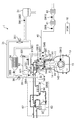
以下、火花点火式ガソリンエンジンの制御装置の実施形態を図面に基づいて説明する。以下の好ましい実施形態の説明は、例示である。図1,2は、エンジン(エンジン本体)1の概略構成を示す。このエンジン1は、車両に搭載されると共に、少なくともガソリンを含有する燃料が供給される火花点火式ガソリンエンジンである。エンジン1は、複数の気筒18(一つのみ図示)が設けられたシリンダブロック11と、このシリンダブロック11上に配設されたシリンダヘッド12と、シリンダブロック11の下側に配設され、潤滑油が貯留されたオイルパン13とを有している。各気筒18内には、コンロッド142を介してクランクシャフト15と連結されているピストン14が往復動可能に嵌挿されている。ピストン14の頂面には、ディーゼルエンジンでのリエントラント型のようなキャビティ141が形成されている。キャビティ141は、ピストン14が圧縮上死点付近に位置するときには、後述するインジェクタ67に相対する。尚、キャビティ141の形状についての詳細は後述する。
Hereinafter, an embodiment of a control device for a spark ignition gasoline engine will be described with reference to the drawings. The following description of preferred embodiments is exemplary. 1 and 2 show a schematic configuration of an engine (engine body) 1. The
シリンダヘッド12と、気筒18と、キャビティ141を有するピストン14とは、燃焼室19を区画する(図3(b)参照)。尚、燃焼室19の形状は、図示する形状に限定されるものではない。例えばキャビティ141の形状、ピストン14の頂面形状、及び、燃焼室19の天井部の形状等は、適宜変更することが可能である。
The
このエンジン1は、理論熱効率の向上や、後述する圧縮着火燃焼の安定化等を目的として、15以上の比較的高い幾何学的圧縮比に設定されている。尚、幾何学的圧縮比は15以上20以下程度の範囲で、適宜設定すればよい。
The
シリンダヘッド12には、気筒18毎に、吸気ポート16及び排気ポート17が形成されていると共に、これら吸気ポート16及び排気ポート17には、燃焼室19側の開口を開閉する吸気弁21及び排気弁22がそれぞれ配設されている。
The
吸気弁21及び排気弁22をそれぞれ駆動する動弁系の内、排気側には、排気弁22の作動モードを通常モードと特殊モードとに切り替える、例えば油圧作動式の可変機構(図2参照。以下、VVL(Variable Valve Lift)と称する)71が設けられている。VVL71は、その構成の詳細な図示は省略するが、カム山を一つ有する第1カムとカム山を2つ有する第2カムとの、カムプロファイルの異なる2種類のカム、及び、その第1及び第2カムのいずれか一方のカムの作動状態を選択的に排気弁に伝達するロストモーション機構を含んで構成されている。第1カムの作動状態を排気弁22に伝達しているときには、排気弁22は、排気行程中において一度だけ開弁される通常モードで作動するのに対し、第2カムの作動状態を排気弁22に伝達しているときには、排気弁22が、排気行程中において開弁すると共に、吸気行程中においても開弁するような、いわゆる排気の二度開きを行う特殊モードで作動する。VVL71の通常モードと特殊モードとは、エンジンの運転状態に応じて切り替えられる。具体的に、特殊モードは、内部EGRに係る制御の際に利用される。尚、こうした通常モードと特殊モードとの切り替えを可能にする上で、排気弁22を電磁アクチュエータによって駆動する電磁駆動式の動弁系を採用してもよい。また、内部EGRの実行は、排気の二度開きのみによって実現されるのではない。例えば吸気弁21を二回開く、吸気の二度開きによって内部EGR制御を行ってもよいし、排気行程乃至吸気行程において吸気弁21及び排気弁22の双方を閉じるネガティブオーバーラップ期間を設けて既燃ガスを気筒18内に残留させる内部EGR制御を行ってもよい。
Among the valve systems that drive the
VVL71を備えた排気側の動弁系に対し、吸気側には、図2に示すように、クランクシャフト15に対する吸気カムシャフトの回転位相を変更することが可能な位相可変機構(以下、VVT(Variable Valve Timing)と称する)72と、吸気弁21のリフト量を連続的に変更することが可能なリフト量可変機構(以下、CVVL(Continuously Variable Valve Lift)と称する)73とが設けられている。VVT72は、液圧式、電磁式又は機械式の公知の構造を適宜採用すればよく、その詳細な構造についての図示は省略する。また、CVVL73も、公知の種々の構造を適宜採用することが可能であり、その詳細な構造についての図示は省略する。VVT72及びCVVL73によって、吸気弁21はその開弁タイミング及び閉弁タイミング、並びに、リフト量をそれぞれ変更することが可能である。
As shown in FIG. 2, the exhaust side valve system having the
シリンダヘッド12にはまた、気筒18毎に、気筒18内に燃料を直接噴射するインジェクタ67が取り付けられている。インジェクタ67は、図3(b)に拡大して示すように、その噴口が燃焼室19の天井面の中央部分から、その燃焼室19内に臨むように配設されている。インジェクタ67は、エンジン1の運転状態に応じた噴射タイミングでかつ、エンジン1の運転状態に応じた量の燃料を、燃焼室19内に直接噴射する。この例において、インジェクタ67は、詳細な図示は省略するが、複数の噴口を有する多噴口型のインジェクタである。これによって、インジェクタ67は、燃料噴霧が放射状に広がるように、燃料を噴射する。図3(b)に矢印で示すように、ピストン14が圧縮上死点付近に位置するタイミングで、燃焼室19の中央部分から放射状に広がるように噴射された燃料噴霧は、ピストン頂面に形成されたキャビティ141の壁面に沿って流動することにより、後述する点火プラグ25、26の周囲に到達するようになる。キャビティ141は、ピストン14が圧縮上死点付近に位置するタイミングで噴射された燃料噴霧を、その内部に収めるように形成されている、と言い換えることが可能である。この多噴口型のインジェクタ67とキャビティ141との組み合わせは、燃料の噴射後、点火プラグ25、26の周りに燃料噴霧が到達するまでの時間を短くすると共に、燃焼期間を短くする上で有利な構成である。
In addition, an
インジェクタ67の燃料の噴射角度θは、比較的狭い角度(例えば45°程度)に設定されている。この狭い噴射角度θは、詳しくは後述するが、ピストン14の位置が、上死点から若干離れた下方に位置しているタイミングで燃料を噴射しても、気筒18の壁面に燃料が付着することを抑制しつつ、噴射した燃料をキャビティ141内に収めることを可能にする。狭い噴射角度θはまた、図3(c)に示すように、キャビティ141のリップ径(キャビティの上端開口径)を比較的小さくし、それに伴いスキッシュエリアを拡大する上でも有利な構成である。尚、スキッシュエリアの拡大は、後述するように、燃焼期間の短縮に有利になる。
The fuel injection angle θ of the
インジェクタ67は、多噴口型のインジェクタに限定されず、外開弁タイプのインジェクタを採用してもよい。
The
図外の燃料タンクとインジェクタ67との間は、燃料供給経路によって互いに連結されている。この燃料供給経路上には、燃料ポンプ63とコモンレール64とを含みかつ、インジェクタ67に、比較的高い燃料圧力で燃料を供給することが可能な燃料供給システム62が介設されている。燃料ポンプ63は、燃料タンクからコモンレール64に燃料を圧送し、コモンレール64は圧送された燃料を、比較的高い燃料圧力で蓄えることが可能である。インジェクタ67が開弁することによって、コモンレール64に蓄えられている燃料がインジェクタ67の噴口から噴射される。ここで、燃料ポンプ63は、図示は省略するが、プランジャー式のポンプであり、例えばクランク軸とカム軸との間のタイミングベルトに連結されることにより、エンジン1によって駆動される。このエンジン駆動のポンプを含む構成の燃料供給システム62は、40MPa以上の高い燃料圧力の燃料を、インジェクタ67に供給することを可能にする。インジェクタ67に供給される燃料の圧力は、後述するように、エンジン1の運転状態に応じて変更される。尚、燃料供給システム62は、この構成に限定されるものではない。
A fuel tank (not shown) and the
シリンダヘッド12にはまた、図3に示すように、燃焼室19内の混合気に点火する点火プラグ25、26が取り付けられている(尚、図1では、点火プラグの図示を省略している)。このエンジン1は、点火プラグとして、第1点火プラグ25及び第2点火プラグ26の2つの点火プラグを備えている。2つの点火プラグ25、26は、各気筒18について2つずつ設けられた吸気弁21と排気弁22との間の位置のそれぞれにおいて、互いに相対するように配置され、それぞれ気筒18の中心軸に向かって斜め下向きに延びるように、シリンダヘッド12内を貫通して取り付けられている。こうして、図3(b)に示すように、各点火プラグ25、26の先端は、燃焼室19の中央部分に配置されたインジェクタ67の先端近傍で、燃焼室19内に臨んで配置される。ここで、前述の通り、ピストン14のキャビティ141のリップ径が、比較的小さく設定されているため、キャビティ141には、第1点火プラグ25及び第2点火プラグ26との干渉を回避するために、2つの凹部143、143が、径方向に相対するように形成されている(図3(b)(c)参照)。こうすることで、図3(a)(c)から明らかなように、キャビティ141の本体部分の形状は円形状となり、キャビティ141の中心位置においてインジェクタ76から放射状に噴射された燃料噴霧は、キャビティ141内においてほぼ均一に広がって、均質な混合気を形成することが可能になる。
As shown in FIG. 3, ignition plugs 25 and 26 that ignite the air-fuel mixture in the
エンジン1の一側面には、図1に示すように、各気筒18の吸気ポート16に連通するように吸気通路30が接続されている。一方、エンジン1の他側面には、各気筒18の燃焼室19からの既燃ガス(排気ガス)を排出する排気通路40が接続されている。
As shown in FIG. 1, an
吸気通路30の上流端部には、吸入空気を濾過するエアクリーナ31が配設されている。また、吸気通路30における下流端近傍には、サージタンク33が配設されている。このサージタンク33よりも下流側の吸気通路30は、各気筒18毎に分岐する独立通路とされ、これら各独立通路の下流端が各気筒18の吸気ポート16にそれぞれ接続されている。
An
吸気通路30におけるエアクリーナ31とサージタンク33との間には、空気を冷却又は加熱する、水冷式のインタークーラ/ウォーマ34と、各気筒18への吸入空気量を調節するスロットル弁36とが配設されている。吸気通路30にはまた、インタークーラ/ウォーマ34をバイパスするインタークーラバイパス通路35が接続されており、このインタークーラバイパス通路35には、当該通路35を通過する空気流量を調整するためのインタークーラバイパス弁351が配設されている。インタークーラバイパス弁351の開度調整を通じて、インタークーラバイパス通路35の通過流量とインタークーラ/ウォーマ34の通過流量との割合を調整することにより、気筒18に導入する新気の温度を調整する。
Between the
排気通路40の上流側の部分は、各気筒18毎に分岐して排気ポート17の外側端に接続された独立通路と該各独立通路が集合する集合部とを有する排気マニホールドによって構成されている。この排気通路40における排気マニホールドよりも下流側には、排気ガス中の有害成分を浄化する排気浄化装置として、直キャタリスト41とアンダーフットキャタリスト42とがそれぞれ接続されている。直キャタリスト41及びアンダーフットキャタリスト42はそれぞれ、筒状ケースと、そのケース内の流路に配置した、例えば三元触媒とを備えて構成されている。
The upstream portion of the
吸気通路30におけるサージタンク33とスロットル弁36との間の部分と、排気通路40における直キャタリスト41よりも上流側の部分とは、排気ガスの一部を吸気通路30に還流するためのEGR通路50を介して接続されている。このEGR通路50は、排気ガスをエンジン冷却水によって冷却するためのEGRクーラ52が配設された主通路51と、EGRクーラ52をバイパスするためのEGRクーラバイパス通路53と、を含んで構成されている。主通路51には、排気ガスの吸気通路30への還流量を調整するためのEGR弁511が配設され、EGRクーラバイパス通路53には、EGRクーラバイパス通路53を流通する排気ガスの流量を調整するためのEGRクーラバイパス弁531が配設されている。
A portion between the
このように構成されたエンジン1は、パワートレイン・コントロール・モジュール(以下、PCMという)10によって制御される。PCM10は、CPU、メモリ、カウンタタイマ群、インターフェース及びこれらのユニットを接続するパスを有するマイクロプロセッサで構成されている。このPCM10が制御器を構成する。
The
PCM10には、図1,2に示すように、各種のセンサSW1〜SW16の検出信号が入力される。この各種のセンサには、次のセンサが含まれる。すなわち、エアクリーナ31の下流側で、新気の流量を検出するエアフローセンサSW1及び新気の温度を検出する吸気温度センサSW2、インタークーラ/ウォーマ34の下流側に配置されかつ、インタークーラ/ウォーマ34を通過した後の新気の温度を検出する、第2吸気温度センサSW3、EGR通路50における吸気通路30との接続部近傍に配置されかつ、外部EGRガスの温度を検出するEGRガス温センサSW4、吸気ポート16に取り付けられかつ、気筒18内に流入する直前の吸気の温度を検出する吸気ポート温度センサSW5、シリンダヘッド12に取り付けられかつ、気筒18内の圧力を検出する筒内圧センサSW6、排気通路40におけるEGR通路50の接続部近傍に配置されかつ、それぞれ排気温度及び排気圧力を検出する排気温センサSW7及び排気圧センサSW8、直キャタリスト41の上流側に配置されかつ、排気中の酸素濃度を検出するリニアO2センサSW9、直キャタリスト41とアンダーフットキャタリスト42との間に配置されかつ、排気中の酸素濃度を検出するラムダO2センサSW10、エンジン冷却水の温度を検出する水温センサSW11、クランクシャフト15の回転角を検出するクランク角センサSW12、車両のアクセルペダル(図示省略)の操作量に対応したアクセル開度を検出するアクセル開度センサSW13、吸気側及び排気側のカム角センサSW14,SW15、及び、燃料供給システム62のコモンレール64に取り付けられかつ、インジェクタ67に供給する燃料圧力を検出する燃圧センサSW16である。
As shown in FIGS. 1 and 2, detection signals from various sensors SW <b> 1 to SW <b> 16 are input to the
PCM10は、これらの検出信号に基づいて種々の演算を行うことによってエンジン1や車両の状態を判定し、これに応じてインジェクタ67、第1及び第2点火プラグ25、26、吸気弁側のVVT72及びCVVL73、排気弁側のVVL71、燃料供給システム62、並びに、各種の弁(スロットル弁36、インタークーラバイパス弁351、EGR弁511、及びEGRクーラバイパス弁531)のアクチュエータへ制御信号を出力する。こうしてPCM10は、エンジン1を運転する。
The
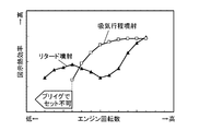
図4は、エンジン1の運転領域の一例を示している。このエンジン1は、燃費の向上や排気エミッションの向上を目的として、エンジン負荷が相対的に低い低負荷域では、点火プラグ25、26による点火を行わずに、圧縮自己着火によって燃焼を行う圧縮着火燃焼を行う。しかしながら、エンジン1の負荷が高くなるに従って、圧縮着火燃焼では、燃焼が急峻になりすぎてしまい、例えば燃焼騒音等の問題を引き起こすことになる。そのため、このエンジン1では、エンジン負荷が相対的に高い高負荷域では、圧縮着火燃焼を止めて、点火プラグ25、26を利用した火花点火燃焼に切り替える。このように、このエンジン1は、エンジン1の運転状態、特にエンジン1の負荷に応じて、圧縮着火燃焼を行うCI(Compression Ignition)モードと、火花点火燃焼を行うSI(Spark Ignition)モードとを切り替えるように構成されている。但し、モード切り替えの境界線は、図例に限定されるものではない。
FIG. 4 shows an example of the operation region of the
CIモードでは基本的に、例えば吸気行程乃至圧縮行程中の、比較的早いタイミングで、インジェクタ67が気筒18内に燃料を噴射することにより、比較的均質なリーン混合気(空気過剰率λ≧1、例えばλ≧2.5)を形成すると共に、その混合気を圧縮上死点付近において圧縮自己着火させる。尚、燃料噴射量は、エンジン1の負荷に応じて設定される。
In the CI mode, for example, the
また、CIモードでは、VVL71の制御によって、排気弁22を吸気行程中に開弁する排気の二度開きを行い、そのことによって内部EGRガスを気筒18内に導入する。内部EGRガスの導入は圧縮端温度を高め、圧縮着火燃焼を安定化させる。
In the CI mode, the
エンジン負荷の上昇に伴い気筒18内の温度が自然と高まることから、過早着火を回避する観点から、内部EGR量は低下させる。例えばCVVL73の制御によって、吸気弁21のリフト量を調整することにより、内部EGR量を調整してもよい。また、スロットル弁36の開度調整によって、内部EGR量を調整してもよい。
Since the temperature in the
エンジン負荷がさらに高まり、例えば図4に示す運転領域において、CIモードとSIモードとの切り替え境界線付近においては、内部EGRを実行することは、筒内温度が高くなりすぎて、圧縮着火をコントロールすることが困難になる場合がある。そこで、CIモードの運転領域において負荷の高い領域では、内部EGRの実行を止め、その代わりにEGR弁511を開いて、EGRクーラ52によって冷却された外部EGRガスを、気筒18内に導入するようにしてもよい。このことにより、筒内温度を低く抑えることが可能になり、圧縮着火のコントロールが可能になる。
For example, in the operation region shown in FIG. 4, in the vicinity of the switching boundary line between the CI mode and the SI mode, executing the internal EGR controls the compression ignition because the in-cylinder temperature becomes too high. May be difficult to do. Therefore, in the CI mode operation region, in the high load region, the execution of the internal EGR is stopped, and instead, the
これに対し、SIモードでは基本的に、詳しくは後述するが、吸気行程から膨張行程初期までの間で、インジェクタ67が気筒18内に燃料を噴射することにより、均質乃至成層化した混合気を形成すると共に、圧縮上死点付近において点火を実行することによってその混合気に着火する。SIモードではまた、理論空燃比(λ=1)でエンジン1を運転する。これは、三元触媒の利用を可能にするから、エミッション性能の向上に有利になる。
In contrast, in the SI mode, as will be described later in detail, the
SIモードでは、スロットル弁36を全開にする一方で、EGR弁511の開度調整により、気筒18内に導入する新気量と外部EGRガス量とを調整することにより、充填量を調整する。これは、ポンプ損失の低減と共に、冷却損失の低減にも有効である。また、冷却した外部EGRガスを導入することによって、異常燃焼の回避に寄与すると共に、Raw NOxの生成を抑制するという利点もある。尚、全開負荷域では、EGR弁511を閉弁することにより、外部EGRを中止する。
In the SI mode, while the
このエンジン1の幾何学的圧縮比は、前述の通り、15以上(例えば18)に設定されている。高い圧縮比は、圧縮端温度及び圧縮端圧力を高くするため、CIモードでは、圧縮着火燃焼の安定化に有利になる。一方で、この高圧縮比エンジン1は、高負荷域においてはSIモードに切り替えるため、過早着火やノッキングといった異常燃焼が生じやすくなってしまうという不都合がある。
As described above, the geometric compression ratio of the
そこでこのエンジン1では、先ず、エンジンの運転状態が、最大負荷を含む高負荷の低速域(図4の(1)参照。尚、ここでいう「低速域」は、エンジン1の運転領域を低、中、高速の3つに区分したときの低速域に相当する。)にあるときには、燃料の噴射形態を従来とは大きく異ならせたSI燃焼を実行することによって、異常燃焼を回避するようにしている。具体的に、この燃料の噴射形態は、従来と比較して大幅に高圧化した燃料圧力でもって、圧縮行程後期から膨張行程初期にかけての大幅に遅角した期間(以下、この期間をリタード期間と呼ぶ)内で、インジェクタ67によって、気筒18内に燃料噴射を実行するものである。この特徴的な燃料噴射形態を、以下においては「高圧リタード噴射」又は単に「リタード噴射」と呼ぶ。
Therefore, in this
また、この高圧リタード噴射を行う運転領域よりも低負荷側の領域(図4の(2)参照)においては、詳しくは後述するが、異常燃焼の発生が、前記(1)の領域よりも抑制されることから、燃料の噴射を、リタード期間ではなく、吸気弁21が開弁している吸気行程期間内に行う。以下においては、この燃料噴射形態を「吸気行程噴射」と呼ぶ。吸気行程噴射では、高い燃料圧力が不要になるから、高圧リタード噴射時よりも燃料圧力を低下させ、それにより、燃料ポンプ63の駆動に起因するエンジン1の機械抵抗損失の低減を図る。
Further, in the region on the lower load side (see (2) in FIG. 4) than the operation region in which the high pressure retarded injection is performed, the occurrence of abnormal combustion is suppressed more than in the region (1) described later. Therefore, fuel injection is performed not in the retard period but in the intake stroke period in which the
一方、エンジンの運転状態が高負荷の高速域(図4の(3)参照。尚、ここでいう「高速域」は、エンジン1の運転領域を低、中、高速の3つに区分したときの中速及び高速域に相当する。)にあるときにも、燃料の噴射を、リタード期間ではなく、吸気弁21が開弁している吸気行程期間内に行う。
On the other hand, the operating state of the engine is a high load high speed range (see (3) in FIG. 4). Note that the "high speed range" here is when the operating range of the
先ず、高圧リタード噴射について、図面を参照しながら説明する。図5は、前述した高圧リタード噴射によるSI燃焼(実線)と、吸気行程中に燃料噴射を実行する従来のSI燃焼(破線)とにおける、熱発生率(上図)及び未燃混合気反応進行度(下図)の違いを比較する図である。図5の横軸は、クランク角である。この比較の前提として、エンジン1の運転状態は共に高負荷の低速域であり、噴射する燃料量は、高圧リタード噴射によるSI燃焼と従来のSI燃焼との場合で互いに同じである。
First, high pressure retarded injection will be described with reference to the drawings. FIG. 5 shows the heat generation rate (upper figure) and the progress of the unburned mixture reaction in the SI combustion (solid line) by the high-pressure retarded injection described above and the conventional SI combustion (broken line) in which fuel injection is performed during the intake stroke. It is a figure which compares the difference in a degree (lower figure). The horizontal axis in FIG. 5 is the crank angle. As a premise for this comparison, the operating state of the
先ず、従来のSI燃焼では、吸気行程中に気筒18内に所定量の燃料噴射を実行する(上図の破線)。気筒18内では、その燃料の噴射後、ピストン14が圧縮上死点に至るまでの間に、比較的均質な混合気が形成される。そして、この例では、圧縮上死点以降の、白丸で示す所定タイミングで点火が実行され、それによって燃焼が開始する。燃焼の開始後は、図5の上図に破線で示すように、熱発生率のピークを経て燃焼が終了する。ここで、燃料噴射の開始から燃焼の終了までの間が未燃混合気の反応可能時間(以下、単に反応可能時間という場合がある)に相当し、図5の下図に破線で示すように、この間に未燃混合気の反応は次第に進行する。同図における点線は、未燃混合気が着火に至る反応度である、着火しきい値を示しており、従来のSI燃焼は、低速域であることと相俟って、反応可能時間が非常に長く、その間、未燃混合気の反応が進行し続けてしまうことから、点火の前後に未燃混合気の反応度が着火しきい値を超えてしまい、過早着火又はノッキングといった異常燃焼を引き起こす。
First, in the conventional SI combustion, a predetermined amount of fuel is injected into the
これに対し、高圧リタード噴射は反応可能時間の短縮を図り、そのことによって異常燃焼を回避することを目的とする。すなわち、反応可能時間は、図5にも示しているように、インジェクタ67が燃料を噴射する期間((1)噴射期間)と、噴射終了後、点火プラグ25、26の周りに可燃混合気が形成されるまでの期間((2)混合気形成期間)と、点火によって開始された燃焼が終了するまでの期間((3)燃焼期間)と、を足し合わせた時間、つまり、(1)+(2)+(3)である。高圧リタード噴射は、噴射期間、混合気形成期間及び燃焼期間をそれぞれ短縮し、それによって、反応可能時間を短くする。このことについて、順に説明する。
On the other hand, the high pressure retarded injection aims to shorten the reaction possible time, thereby avoiding abnormal combustion. That is, as shown in FIG. 5, the possible reaction time is the period during which the
先ず、高い燃料圧力は、単位時間当たりにインジェクタ67から噴射される燃料量を相対的に多くする。このため、図6の中段に(1)で示す図のように、燃料噴射量を一定とした場合に、燃料圧力と燃料の噴射期間との関係は概ね、燃料圧力が低いほど噴射期間は長くなり、燃料圧力が高いほど噴射期間は短くなる。従って、燃料圧力が従来に比べて大幅に高く設定された高圧リタード噴射は、噴射期間を短縮する。
First, the high fuel pressure relatively increases the amount of fuel injected from the
また、高い燃料圧力は、気筒18内に噴射する燃料噴霧の微粒化に有利になると共に、燃料噴霧の飛翔距離を、より長くする。このため、図6の下段に(A)で示す図のように、燃料圧力と燃料蒸発時間との関係は概ね、燃料圧力が低いほど燃料蒸発時間は長くなり、燃料圧力が高いほど燃料蒸発時間は短くなる。また、図6の下段に(B)で示す図のように、燃料圧力と点火プラグ25、26の周りに燃料噴霧が到達するまでの時間は概ね、燃料圧力が低いほど到達までの時間は長くなり、燃料圧力が高いほど到達までの時間は短くなる。尚、点火プラグ25、26の周りに燃料噴霧が到達するまでの時間は、インジェクタ67の先端から点火プラグ25又は点火プラグ26までの噴霧飛翔距離と、燃料圧力
に比例する燃料噴射速度と、から算出可能である。混合気形成期間は、燃料蒸発時間と、点火プラグ25、26の周りへの燃料噴霧到達時間とを足し合わせた時間((A)+(B))であるから、図6の中段に(2)で示す図のように、燃料圧力が高いほど混合気形成期間は短くなる。従って、燃料圧力が従来に比べて大幅に高く設定された高圧リタード噴射は、燃料蒸発時間及び点火プラグ25、26の周りへの燃料噴霧到達時間がそれぞれ短くなる結果、混合気形成期間を短縮する。これに対し、同図に白丸で示すように、従来の、低い燃料圧力での吸気行程噴射は、混合気形成期間が大幅に長くなる。尚、前述したように、多噴口型のインジェクタ67とキャビティ141との組み合わせは、燃料の噴射後、点火プラグ25、26の周りに燃料噴霧が到達するまでの時間を短くする結果、混合気形成期間の短縮に有効である。
Further, the high fuel pressure is advantageous for atomization of the fuel spray injected into the
このように、噴射期間及び混合気形成期間を短縮することは、燃料の噴射タイミング、より正確には、噴射開始タイミングを、比較的遅いタイミングにすることを可能にする。そこで、高圧リタード噴射では、図5の上図に示すように、圧縮行程後期から膨張行程初期にかけてのリタード期間内に燃料噴射を行う。高い燃料圧力で気筒18内に燃料を噴射することに伴い、その気筒内の乱れが強くなり、気筒18内の乱れエネルギが高まるが、この高い乱れエネルギは、燃料噴射のタイミングが比較的遅いタイミングに設定されることと相俟って、燃焼期間の短縮に有利になる。
Thus, shortening the injection period and the mixture formation period makes it possible to set the fuel injection timing, more precisely, the injection start timing to a relatively late timing. Therefore, in the high pressure retarded injection, as shown in the upper diagram of FIG. 5, the fuel is injected within the retard period from the latter stage of the compression stroke to the early stage of the expansion stroke. As the fuel is injected into the
すなわち、図6の下段に(D)で示す図のように、燃料噴射をリタード期間内に行った場合、燃料圧力と燃焼期間内での乱流エネルギとの関係は概ね、燃料圧力が低いほど乱流エネルギが低くなり、燃料圧力が高いほど乱流エネルギは高くなる。尚、同図に破線で示す線は、燃料噴射を吸気行程中に行った場合の例である。仮に高い燃料圧力で気筒18内に燃料を噴射するとしても、その噴射タイミングが吸気行程中にある場合は、点火タイミングまでの時間が長いことや、吸気行程後の圧縮行程において気筒18内が圧縮されることに起因して、気筒18内の乱れは減衰してしまう。その結果、吸気行程中に燃料噴射を行った場合、燃焼期間内での乱流エネルギは、燃料圧力の高低に拘わらず比較的低くなってしまう。
That is, when the fuel injection is performed within the retard period as shown in (D) in the lower part of FIG. 6, the relationship between the fuel pressure and the turbulent energy within the combustion period is generally lower as the fuel pressure is lower. The turbulent energy increases as the turbulent energy decreases and the fuel pressure increases. In addition, the line shown with a broken line in the same figure is an example at the time of performing fuel injection during an intake stroke. Even if fuel is injected into the
図6の下段に(C)で示す図のように、燃焼期間での乱流エネルギと燃焼期間との関係は概ね、乱流エネルギが低いほど燃焼期間が長くなり、乱流エネルギが高いほど燃焼期間が短くなる。従って、図6の(C)(D)から、燃料圧力と燃焼期間との関係は、図6の中段に(3)で示す図のように、燃料圧力が低いほど燃焼期間は長くなり、燃料圧力が高いほど燃焼期間は短くなる。すなわち、高圧リタード噴射は、燃焼期間を短縮する。これに対し、同図に白丸で示すように、従来の、低い燃料圧力での吸気行程噴射は、燃焼期間が長くなる。尚、多噴口型のインジェクタ67は、気筒18内の乱れエネルギの向上に有利であって、燃焼期間の短縮に有効であると共に、その多噴口型のインジェクタ67とキャビティ141との組み合わせによって、燃料噴霧をキャビティ141内に収めることもまた、燃焼期間の短縮に有効である。
As shown in FIG. 6 (C) in the lower part of FIG. 6, the relationship between the turbulent energy and the combustion period in the combustion period is generally such that the lower the turbulent energy, the longer the combustion period and the higher the turbulent energy, the more The period is shortened. Accordingly, from (C) and (D) of FIG. 6, the relationship between the fuel pressure and the combustion period is as shown in (3) in the middle of FIG. The higher the pressure, the shorter the combustion period. That is, the high pressure retarded injection shortens the combustion period. On the other hand, as indicated by white circles in the figure, the conventional intake stroke injection at a low fuel pressure has a long combustion period. The
図6の(3)の図に示す燃料圧力と燃焼期間との関係から、言い換えると、その曲線形状から、燃料圧力を例えば40MPa以上に設定することによって、燃焼期間を効果的に短縮化することが可能である。また、40MPa以上の燃料圧力は、噴射期間及び混合気形成期間も、それぞれ有効に短縮化することが可能である。尚、燃料圧力は、少なくともガソリンを含有する、使用燃料の性状に応じて適宜設定するのが好ましい。その上限値は、一例として、120MPaとしてもよい。 From the relationship between the fuel pressure and the combustion period shown in FIG. 6 (3), in other words, from the curved shape, the combustion period is effectively shortened by setting the fuel pressure to 40 MPa or more, for example. Is possible. Moreover, the fuel pressure of 40 MPa or more can effectively shorten both the injection period and the mixture formation period. The fuel pressure is preferably set as appropriate according to the properties of the fuel used, which contains at least gasoline. The upper limit may be 120 MPa as an example.
このように高圧リタード噴射は、噴射期間、混合気形成期間、及び、燃焼期間をそれぞれ短縮し、その結果、図5に示すように、燃料の噴射開始タイミングSOIから燃焼終了時期θendまでの、未燃混合気の反応可能時間を、従来の吸気行程中での燃料噴射の場合と比較して大幅に短くすることを可能にする。この反応可能時間を短縮する結果、図6の上段に示す図のように、従来の低い燃料圧力での吸気行程噴射では、白丸で示すように、燃焼終了時における未燃混合気の反応進行度が、着火しきい値を超えてしまい、異常燃焼が発生してしまうところ、高圧リタード噴射は、黒丸で示すように、燃焼終了時における未燃混合気の反応の進行を抑制し、異常燃焼を回避することが可能になる。尚、図6の上図における白丸と黒丸とで、点火タイミングは互いに同じタイミングに設定している。 As described above, the high pressure retarded injection shortens the injection period, the mixture formation period, and the combustion period, and as a result, as shown in FIG. 5, the fuel injection start timing SOI to the combustion end timing θend are not changed. It is possible to significantly shorten the reaction time of the fuel mixture as compared with the case of fuel injection during the conventional intake stroke. As a result of shortening this reaction possible time, as shown in the upper diagram of FIG. 6, in the conventional intake stroke injection at a low fuel pressure, as shown by a white circle, the reaction progress of the unburned mixture at the end of combustion is shown. However, when the ignition threshold is exceeded and abnormal combustion occurs, the high-pressure retarded injection suppresses the progress of the reaction of the unburned mixture at the end of combustion, as shown by the black circle, to prevent abnormal combustion. It can be avoided. It should be noted that the ignition timing is set to the same timing in the white circle and the black circle in the upper diagram of FIG.
高圧リタード噴射は、気筒18内への燃料噴射の形態を工夫することによって異常燃焼を回避する。これとは異なり、異常燃焼の回避を目的として点火タイミングを遅角することが、従来から知られている。点火タイミングの遅角化は、未燃混合気の温度及び圧力の上昇を抑制することによって、その反応の進行を抑制する。しかしながら、点火タイミングの遅角化は熱効率及びトルクの低下を招くのに対し、高圧リタード噴射を行う場合は、燃料噴射の形態の工夫によって異常燃焼を回避する分、点火タイミングを進角させることが可能であるから、熱効率及びトルクが向上する。つまり、高圧リタード噴射は、異常燃焼を回避するだけでなく、その回避可能な分だけ、点火タイミングを進角することを可能にして、燃費の向上に有利になる。
High pressure retarded injection avoids abnormal combustion by devising the form of fuel injection into the
一方で、高圧リタード噴射は、高い燃料圧力を必要とするため、前述の通り、エンジン1の機械抵抗損失を増大してしまうという不都合がある。そのため、高圧リタード噴射を行う領域をできるだけ小さくしたいという要求がある。そこで、図4に示すマップにおいて、全開負荷を含む領域(1)よりも低負荷側の領域は、低回転であっても負荷が低い分、圧縮端温度及び圧縮端圧力が低くなる等の要因で異常燃焼が回避され易い。そこで、このエンジン1では、低負荷側の(2)の領域では、高圧リタード噴射を行わず、吸気行程噴射を行う。
On the other hand, since high pressure retarded injection requires high fuel pressure, there is a disadvantage that the mechanical resistance loss of the
図8は、高圧リタード噴射(同図(a)参照)と、吸気行程噴射(同図(b)参照)との噴射タイミング及び点火タイミングを比較する図である。尚、図に示す噴射タイミングや点火タイミングは、高圧リタード噴射及び吸気行程噴射の一例であり、噴射タイミングや点火タイミングは図例のタイミングに限定されない。 FIG. 8 is a diagram comparing the injection timing and ignition timing of high-pressure retarded injection (see (a) in the figure) and intake stroke injection (see (b) in the same figure). The injection timing and ignition timing shown in the figure are examples of high-pressure retarded injection and intake stroke injection, and the injection timing and ignition timing are not limited to the timing shown in the figure.
前述の通り、高圧リタード噴射では、圧縮行程後期から膨張行程初期にかけてのリタード期間内(図例では、圧縮上死点前の圧縮行程後期)に燃料噴射を行い、圧縮上死点近傍において点火を行う。この点火は、第1点火プラグ25、又は、第2点火プラグ26のいずれか一方を駆動させることによって行う。高圧リタード噴射によって十分に短い燃焼期間が確保されるためである。これによって、燃焼が開始し、同図に実線で示すように、熱発生率のピークを経て燃焼が終了する。尚、第1及び第2点火プラグ25、26の双方を駆動させてもよい。
As described above, in the high pressure retarded injection, fuel is injected during the retard period from the latter half of the compression stroke to the early stage of the expansion stroke (in the illustrated example, the latter half of the compression stroke before the compression top dead center), and ignition is performed near the compression top dead center. Do. This ignition is performed by driving either the
この高圧リタード噴射に対し、吸気行程噴射では、吸気行程期間内に燃料噴射を行う。この吸気行程噴射は、ピストン14のキャビティ141内に燃料をできるだけ収めるために、ピストン14の位置が吸気上死点近傍にあるタイミングで行うことが好ましい。尚、前述の通り、インジェクタ67の噴射角度θが比較的狭い角度に設定されていることから、ピストン14が吸気上死点から多少離れていても、燃料はキャビティ141内に収まりやすい。つまり、インジェクタ67の噴射角度θを狭く設定することは、吸気行程噴射における燃料の噴射タイミングの自由度を高める。
In contrast to this high pressure retarded injection, in the intake stroke injection, fuel injection is performed within the intake stroke period. The intake stroke injection is preferably performed at a timing at which the position of the
吸気行程噴射では、気筒内の圧力が比較的低い状態で燃料を噴射する上に、前述したような未燃混合気の反応時間を短縮するような要求もないため、高圧リタード噴射のような高い燃料圧力が不要である。そこで、吸気行程噴射では、燃料圧力を、高圧リタード噴射時の燃料圧力よりも低下させる。燃料圧力は、40MPa未満、例えば20MPa程度に設定してもよい。これは、燃料ポンプ63の駆動を抑制し、エンジン1の機械損失が低下するため、燃費の向上に有利になる。
In the intake stroke injection, fuel is injected with a relatively low pressure in the cylinder, and there is no requirement to shorten the reaction time of the unburned mixture as described above. No fuel pressure is required. Therefore, in the intake stroke injection, the fuel pressure is made lower than the fuel pressure during the high pressure retarded injection. The fuel pressure may be set to less than 40 MPa, for example, about 20 MPa. This suppresses the driving of the
この(2)の領域における点火は、(1)の領域と同様に、第1点火プラグ25、又は、第2点火プラグ26のいずれか一方を駆動させることによって行う。これによって、燃焼が開始し、同図に実線で示すように、熱発生率のピークを経て燃焼が終了する。尚、第1及び第2点火プラグ25、26の双方を駆動させてもよい。
The ignition in the region (2) is performed by driving either the
また、前述の通り、高圧リタード噴射は、燃料噴射をリタード期間内に行うことによって未燃混合気の反応可能時間を短縮させるものの、この反応可能時間の短縮は、エンジン1の回転数が比較的低い低速域においては、クランク角変化に対する実時間が長いため、有効であるのに対し、エンジン1の回転数が比較的高い高速域においては、クランク角変化に対する実時間が短いため、それほど有効でない。例えば図7に示すように、リタード噴射は、エンジン回転数が比較的低いときには、高い図示熱効率が得られる一方で、エンジン回転数が高くなると、図示熱効率が低下してしまう。これは、リタード噴射では、燃料噴射時期を圧縮上死点付近に設定するため、圧縮行程においては、燃料を含まない、言い換えると比熱比の高い空気が圧縮されることになるためである。つまり、比熱比の高い空気を圧縮する結果、圧縮上死点における気筒18内の温度(つまり、圧縮端温度)を高くしてしまい、この高い圧縮端温度がノッキングを招くことになる。そのため、高速時にリタード噴射行うときには、点火タイミングを遅角化して、ノッキングを回避しなければならない。このことが、図7に示すように、リタード噴射時の高回転での熱効率の低下を招くのである。
In addition, as described above, the high pressure retarded injection shortens the reaction time of the unburned mixture by performing the fuel injection within the retard period. In the low low speed range, the actual time for the crank angle change is long and effective. On the other hand, in the high speed range where the
そこで、このエンジン1では、高負荷の高速域である(3)の領域においては、リタード噴射ではなく、吸気行程噴射を行う。この吸気行程噴射は、吸気弁21が閉じるまでの、言い換えると吸気弁21が開いている間の吸気行程期間内において行う。エンジン1の運転領域が高負荷の高速域であるときには、吸気弁21の閉弁タイミングは、吸気下死点よりも遅く設定される場合がある。尚、前記と同様に、この吸気行程噴射は、ピストン14のキャビティ141内に燃料をできるだけ収めるために、ピストン14の位置が吸気上死点近傍にあるタイミングで行うことが好ましい。また、この(3)の領域においても、燃料圧力を、高圧リタード噴射時の燃料圧力よりも低下させる(例えば40MPa未満)。これは、燃料ポンプ63の駆動を抑制し、エンジン1の機械損失が低下するため、燃費の向上に有利になる。
Therefore, in the
吸気行程噴射では、圧縮行程中の筒内ガス(つまり、燃料を含む混合気)の比熱比を下げ、それによって圧縮端温度を低く抑えることが可能である。こうして圧縮端温度が低くなることで、ノッキングを抑制することが可能になるから、点火タイミングを進角させることが可能になる。そこで、(3)の領域においては、高圧リタード噴射と同様に、圧縮上死点付近において点火を行う。但し、(3)の領域においては、燃焼期間を短縮させる観点から、その点火は、第1及び第2点火プラグ25、26を共に駆動させる二点点火とする。第1及び第2点火プラグ25、26は同時に点火を行えばよい。第1及び第2点火プラグ25、26を時間差をおいて駆動してもよい。 In the intake stroke injection, it is possible to lower the specific heat ratio of the in-cylinder gas (that is, the air-fuel mixture containing fuel) during the compression stroke, thereby keeping the compression end temperature low. Since the compression end temperature is lowered in this manner, knocking can be suppressed, so that the ignition timing can be advanced. Therefore, in the region (3), ignition is performed in the vicinity of the compression top dead center, as in the high pressure retarded injection. However, in the region (3), from the viewpoint of shortening the combustion period, the ignition is a two-point ignition that drives both the first and second spark plugs 25 and 26. The first and second spark plugs 25 and 26 may be ignited simultaneously. The first and second spark plugs 25 and 26 may be driven with a time difference.
ここで、(1)の領域と(2)の領域との境界である第2負荷は、気筒18内の状態に応じて変更してもよい。例えば外気温が低いときや、エンジン水温が低いとき等、気筒18内の圧縮端温度及び圧縮端圧力が比較的低くなるときには、過早着火やノッキング等の異常燃焼が発生し難くなる。そこで、このような条件下では、(2)の領域が拡大するように、第2負荷を高めに設定してもよい。こうすることで、燃料圧力を無駄に高くすることがなくなり、異常燃焼を回避しつつも、燃費の向上に有利になる。
Here, the second load, which is the boundary between the region (1) and the region (2), may be changed according to the state in the
図9〜図11は、低速域内における負荷の変動に対するエンジン1の各パラメータ、つまり、(b)スロットル弁36の開度、(c)EGR弁511の開度、(d)排気弁22の二度開きの閉弁タイミング、(e)吸気弁21の開弁タイミング、(f)吸気弁21の閉弁タイミング、及び、(g)吸気弁のリフト量それぞれの制御例を示している。
9 to 11 show various parameters of the
図9(a)は、気筒18内の状態を示している。同図は、横軸をトルク(言い換えるとエンジン負荷)、縦軸を気筒内の混合気充填量として、気筒内の混合気の構成を示している。前述の通り、相対的に負荷の低い、図の左側の領域はCIモードとなり、所定負荷よりも負荷が高い、図の右側の領域はSIモードとなる。燃料量(総括燃料量)は、CIモード及びSIモードに拘わらず、負荷の増大に従って増量される。この燃料量に対して、理論空燃比(λ=1)となるための新気量が設定されることとなり、この新気量は、負荷の増大に対し、燃料量の増量に伴って増量することになる。
FIG. 9A shows the state in the
CIモードにおいては、前述の通り、内部EGRガスが気筒18内に導入されることから、充填量の残り分は、内部EGRガスと余剰の新気とによって構成される。従って、CIモードでは、リーン混合気となる。
In the CI mode, as described above, since the internal EGR gas is introduced into the
一方、SIモードにおいてはλ=1となるようにエンジン1が運転されると共に、内部EGRガスの導入が中止される。制御例の一つとして、図9では、SIモードにおいては、外部EGRガスを気筒18内に導入するようにし、気筒18内への充填量を減らさない。
On the other hand, in the SI mode, the
気筒18内の状態が、図9(a)に示すような状態となるように、スロットル弁36は、同図(b)に示すように、エンジン1の負荷の高低に拘わらず全開に設定される。一方で、同図(c)に示すように、EGR弁511は、CIモードでは閉じられたままになるのに対し、SIモードでは開弁される。EGR弁511の開度は、SIモードにおいて低負荷ほど大きく高負荷ほど小さくなるように、エンジン負荷の増大に伴い次第に小さくされる。より正確には、CIモードとSIモードとの切り替わりにおいては全開とされ、全開負荷において全閉とされる。従ってこの制御例では、SIモードにおいても、全開負荷時には外部EGRガスは気筒18内に導入されない。
As shown in FIG. 9B, the
図9(d)は、排気弁22の二度開き時の閉弁タイミングを示している。CIモードでは、前述の通り、内部EGRガスを気筒18内に導入すべく、その閉弁タイミングが排気上死点と吸気下死点との間の、所定タイミングに設定される。一方、SIモードでは、その閉弁タイミングが排気上死点に設定される。つまり、SIモードでは、排気の二度開きが中止される結果、内部EGRの制御が中止される。
FIG. 9D shows the valve closing timing when the
このように、CIモードにおいて所定の閉弁タイミングに設定される排気弁22の二度開きに対して、図9(e)に示すように、吸気弁21の開弁タイミングが、エンジン1の負荷が高くなるほど排気上死点に近づくように進角される。従って、エンジン1の負荷が低いほど、気筒18内に導入される内部EGRガスが増量するのに対し、エンジン1の負荷が高くなればなるほど、気筒18内に導入される内部EGRガスは減少する。エンジン1の負荷が低いほど、大量の内部EGRガスによって気筒18内の圧縮端温度が高まるため、安定した圧縮着火燃焼を実現する上で有利になる。一方、エンジン1の負荷が高いほど、内部EGRガスを抑制することで気筒18内の圧縮端温度の上昇を抑制するため、過早着火を抑制する上で有利になる。尚、SIモードでは、吸気弁21の開弁タイミングは、排気上死点で一定にされる。
In this way, with respect to the double opening of the
一方、図9(f)に示すように、吸気弁21の閉弁タイミングは、CIモードにおいては吸気下死点で一定にされると共に、SIモードにおいても、吸気下死点で一定にされる。
On the other hand, as shown in FIG. 9F, the closing timing of the
さらに、図9(g)に示すように、吸気弁21のリフト量は、CIモードにおいては、エンジン負荷の増大に伴い、最小リフト量から次第に大きくなるのに対し、SIモードにおいては、エンジン負荷の高低に拘わらず、最大リフト量で一定に設定される。
Further, as shown in FIG. 9 (g), the lift amount of the
こうして、SIモードにおいては、EGR弁511の開度調整によって、気筒18内の導入される新気量と、外部EGRガス量との割合が調整されることになる。このような制御は、ポンプ損失の低減に有利である。また、SIモードにおいて、外部EGRガスを気筒18内に導入することは、冷却損失の低減、異常燃焼の回避、及び、Raw NOxの抑制に有利になる。
Thus, in the SI mode, the ratio between the fresh air amount introduced into the
尚、図示は省略するが、SIモードにおいて外部EGRガスを導入する代わりに、充填量を低減するようにしてもよい(例えば図11(a)参照)。こうした充填量制御は、スロットル弁36の開度制御を通じて行ってもよいし、吸気弁21の閉弁タイミングを調整する(つまり、吸気弁21の遅閉じ制御)ことによって行ってもよい。
In addition, although illustration is abbreviate | omitted, instead of introducing external EGR gas in SI mode, you may make it reduce filling amount (for example, refer Fig.11 (a)). Such filling amount control may be performed through the opening degree control of the
次に、図10は、低速域内における負荷の変動に対するエンジン1の各制御パラメータ、すなわち、(b)G/F、(c)噴射タイミング、(d)燃料圧力、(e)燃料噴射パルス幅(つまり、噴射期間)、及び、(f)点火タイミングの変化を示している。
Next, FIG. 10 shows each control parameter of the
先ず、図9の制御例に従う場合は、気筒内の混合気の状態は、図10(a)に示すような構成となる。このため、G/Fは、図10(b)に示すように、CIモードでは、燃料量の増大に伴いリーンから次第に理論空燃比(G/F=14.7)に近づくようになると共に、SIモードでも、CIモードの変化に連続して理論空燃比に近づくようになる。 First, when the control example of FIG. 9 is followed, the state of the air-fuel mixture in the cylinder has a configuration as shown in FIG. For this reason, as shown in FIG. 10B, the G / F gradually approaches the stoichiometric air-fuel ratio (G / F = 14.7) from the lean as the fuel amount increases in the CI mode. Even in the SI mode, the theoretical air-fuel ratio comes close to the change in the CI mode.
図10(c)に示すように、燃料噴射タイミングは、CIモードにおいては、一例として、排気上死点と吸気下死点との間の吸気行程中に設定される。燃料噴射タイミングは、エンジン1の負荷に応じて変更してもよい。そして、SIモードにおいても、相対的に低負荷のとき(つまり、図4における(2)の領域)には、燃料噴射タイミングは、CIモードと同様に、吸気行程中に設定される(つまり、吸気行程噴射)。そうして、SIモードにおいて、相対的に高負荷になれば(つまり、(1)の領域では)、燃料噴射タイミングは、燃料噴射タイミングは、圧縮行程後半から膨張行程初期にかけてのリタード期間に設定される。つまり、高圧リタード噴射である。高圧リタード噴射では、エンジン負荷の増大に伴い、その噴射タイミングは次第に遅角側に変更される。これは、エンジン負荷の増大に伴い、気筒18内の圧力及び温度が高まって異常燃焼が発生しやすくなることから、これを効率的に回避するためには、噴射タイミングを遅角側に設定する必要があるためである。このことを言い換えると、高圧リタード噴射を行うときでも、エンジン負荷が低い間は、燃料圧力を下げることによって、機械抵抗損失を低減して、燃費の向上に有利になる。
As shown in FIG. 10C, the fuel injection timing is set, for example, during the intake stroke between the exhaust top dead center and the intake bottom dead center in the CI mode. The fuel injection timing may be changed according to the load of the
ここで、図10(c)の実線は、高圧リタード噴射を一回の燃料噴射によって行う、一括噴射の場合の、燃料噴射タイミングの一例を示している。これに対し、図10(c)の一点鎖線は、高圧リタード噴射を、第1噴射と第2噴射との二回の燃料噴射に分割した場合の、第1噴射及び第2噴射それぞれの燃料噴射タイミングの一例を示している。これによると、分割噴射における第2噴射は、一括噴射を行う場合よりも、遅角側に実行することになるため、異常燃焼の回避により有利になる。つまり、比較的早期に第1噴射を実行することによって十分な混合気形成期間が確保される分、第2噴射の噴射タイミングは、より一層遅角したタイミングに設定することが可能になる。このことは気筒内の乱れエネルギの向上に有利になり、燃焼期間の短縮に有利になる。 Here, the solid line in FIG. 10C shows an example of fuel injection timing in the case of batch injection in which high-pressure retarded injection is performed by one fuel injection. On the other hand, the alternate long and short dash line in FIG. 10C indicates the fuel injection of each of the first injection and the second injection when the high pressure retarded injection is divided into two fuel injections of the first injection and the second injection. An example of timing is shown. According to this, since the second injection in the divided injection is executed on the retard side as compared with the case of performing the batch injection, it is advantageous for avoiding abnormal combustion. That is, the injection timing of the second injection can be set to a more retarded timing as long as a sufficient mixture formation period is ensured by executing the first injection relatively early. This is advantageous for improving the turbulent energy in the cylinder and for shortening the combustion period.
さらに図10(c)に点線で示すように、全開負荷域においては、総括燃料噴射量が多くなることから、燃料噴射量の増量分を、吸気充填効率の向上を目的として、吸気行程噴射を実行するようにしてもよい。 Further, as indicated by the dotted line in FIG. 10 (c), the overall fuel injection amount increases in the fully open load region. Therefore, the intake stroke injection is performed for the purpose of improving the intake charge efficiency by increasing the fuel injection amount. You may make it perform.
図10(d)は、直噴インジェクタ67に供給される燃料圧力の変化を示しており、CIモードでは低い燃料圧力で一定に設定される。これに対し、SIモードにおける低負荷側では、吸気行程噴射を行うため、CIモード時と同程度の、低い燃料圧力に設定される。一方で、SIモードにおける高負荷側では、高圧リタード噴射を行うため、燃料圧力が相対的に高く設定されると共に、エンジン負荷の増大に伴い、燃料圧力が増大するように設定される。これは、エンジン負荷が高くなるにつれて異常燃焼が発生しやすくなることから、噴射期間のさらなる短縮や、噴射タイミングのさらなる遅角化が求められるためである。
FIG. 10D shows a change in the fuel pressure supplied to the
図10(e)は、一括噴射を行う場合の噴射期間に相当する噴射パルス幅(インジェクタの開弁期間)の変化を示しており、CIモードにおいては、燃料噴射量の増大に伴いパルス幅も大きくなり、SIモードの低負荷側においても同様に、燃料噴射量の増大に伴いパルス幅も大きくなる。しかしながら、同図(d)に示すように、SIモードの高負荷側では、高圧リタード噴射を行うため、CIモードやSIモードの低負荷側よりも燃料圧力が大幅に高く設定される結果、SIモードにおける高負荷側の燃料噴射量は、低負荷側での燃料噴射量よりも多いにも拘わらず、そのパルス幅は、より短く設定される。これは、未燃混合気反応可能時間を短縮し、異常燃焼の回避に有利になる。 FIG. 10 (e) shows the change in the injection pulse width (injector opening period) corresponding to the injection period in the case of performing batch injection. In the CI mode, the pulse width also increases as the fuel injection amount increases. Similarly, on the low load side of the SI mode, the pulse width also increases as the fuel injection amount increases. However, as shown in FIG. 4D, since the high pressure retarded injection is performed on the high load side of the SI mode, the fuel pressure is set to be significantly higher than the low load side of the CI mode or the SI mode. Although the fuel injection amount on the high load side in the mode is larger than the fuel injection amount on the low load side, the pulse width is set shorter. This shortens the unburned mixture reaction possible time and is advantageous for avoiding abnormal combustion.
また、図10(f)は、点火タイミングの変化を示しており、SIモードでは、燃料噴射タイミングがエンジン負荷の増大と共に遅角されることに従って、点火タイミングもまた、エンジン負荷の増大と共に遅角される。これは、異常燃焼の回避に有利である。また、CIモードでは、基本的には点火を実行しないものの、点火プラグ25のくすぶりを回避する目的で、同図に一点鎖線で示すように、例えば排気上死点付近で点火を行ってもよい。
FIG. 10F shows a change in the ignition timing. In the SI mode, as the fuel injection timing is retarded as the engine load increases, the ignition timing also retards as the engine load increases. Is done. This is advantageous for avoiding abnormal combustion. In the CI mode, although ignition is basically not performed, for the purpose of avoiding smoldering of the
図11は、図10とは異なり、SIモードにおいて充填量を低減させる制御を行う場合(同図(a)参照)の、(b)G/F、(c)噴射タイミング、(d)燃料圧力、(e)燃料噴射パルス幅、及び、(f)点火タイミングの変化を示している。尚、図10と、図11との比較において、(c)(e)は、互いに同じである。 FIG. 11 differs from FIG. 10 in that (b) G / F, (c) injection timing, and (d) fuel pressure in the case of performing control for reducing the filling amount in the SI mode (see (a) in the same figure). , (E) Fuel injection pulse width, and (f) Ignition timing change. In comparison between FIG. 10 and FIG. 11, (c) and (e) are the same as each other.
気筒18内の混合気の状態は、図11(a)に示すような構成となり、SIモードにおいては、外部EGRガスを導入せずに、充填量を低減していることから、G/Fは、図11(b)に示すように、SIモードでは、G/Fは理論空燃比で一定になり(G/F=14.7)、CIモードからSIモードにかけて不連続になる。このように、SIモードにおいて外部EGRガスを導入しないことから、特にエンジン1の運転状態が中負荷域にあるときに、図10の制御例とは異なり、燃焼が緩慢にならずに、燃焼期間が相対的に短くなる。そこで、この制御例では、図11(d)に示すように、燃料圧力が低めに設定される(図11(d)の一点鎖線は、図10(d)の燃料圧力を示す)。また、図10(f)と図11(f)とを比較して、図11に示す制御例では、点火タイミングを相対的に遅らせているが、これは外部EGRガスを導入しないことから、過早着火やノッキング等の異常燃焼に不利になる分、点火タイミングを遅らせているものである。
The state of the air-fuel mixture in the
従って、このエンジン1では、図4に示す(1)の領域、すなわち高負荷の低回転域では、高圧リタード噴射とすることで異常燃焼を回避しつつ熱効率を向上させる。一方、図4に示す(2)の領域、すなわち、低回転域であって、(1)の領域よりも低負荷の領域では、異常燃焼を回避しつつも、吸気行程噴射とすることで燃料圧力を低下させて、燃費を向上させる。
Therefore, in the
さらに、このエンジンでは、高負荷の高回転域(図4に示す(3)の領域)でも、吸気行程噴射とすることで、異常燃焼を回避しつつ熱効率を向上させる。また、高負荷の高回転域では、二点点火を行うことによって、燃焼室19内の複数の火種のそれぞれから火炎が広がるため、火炎の広がりが早くて燃焼期間が短くなる。二点点火は、点火タイミングは圧縮上死点以降になったとしても、燃焼重心位置はできるだけ進角側に位置するようになり、熱効率及びトルクの向上、ひいては燃費の向上に有利になる。尚、点火プラグの数は、2個に限定されるものではない。また、高圧リタード噴射時に、多点点火を行ってもよい。
Further, in this engine, even in a high-load high-rotation region (region (3) shown in FIG. 4), the intake stroke injection is performed to improve thermal efficiency while avoiding abnormal combustion. In addition, in the high-load high-rotation region, by performing two-point ignition, a flame spreads from each of the plurality of fire types in the
また、このエンジン1においては、ピストンのリップ径を小さくし、その分、スキッシュエリアを大きくしている。このため、スキッシュが強まり、気筒18内の流動が強くなり、高回転域において、燃焼期間を短くすることが可能である。二点点火と、小さいリップ径との組み合わせは、目標レベル程度にまで燃焼期間を短くすることが可能である。このことは、ノッキングの回避に有利であり、熱効率及びトルクの向上に有利である。
In the
尚、吸気行程期間内における燃料噴射は、気筒18内に設けたインジェクタ67ではなく、別途、吸気ポート16に設けたポートインジェクタを通じて、吸気ポート16内に燃料を噴射してもよい。
In addition, the fuel injection in the intake stroke period may be injected into the
また、ここに開示する技術は、前述したような自然吸気エンジンに限らず、過給機付きエンジンに適用することも可能である。過給機付きエンジンでは、CIモードの領域を高負荷側に拡大させることが可能になる。 Further, the technology disclosed herein can be applied not only to the naturally aspirated engine as described above but also to an engine with a supercharger. In the supercharged engine, the CI mode region can be expanded to the high load side.
さらに、高圧リタード噴射は、必要に応じて分割噴射にしてもよく、同様に、吸気行程噴射もまた、必要に応じて分割噴射にしてもよい。その結果、少なくとも1回の噴射が吸気行程において行われると共に、圧縮行程においても、燃料噴射が行われる場合もあり得る。 Furthermore, the high-pressure retarded injection may be divided as required, and similarly, the intake stroke injection may also be divided as required. As a result, at least one injection is performed in the intake stroke, and fuel injection may be performed in the compression stroke.
加えて、前記の構成では、エンジン1の運転状態が低速域内における低負荷域にあるときには、圧縮着火燃焼を行うCIモードとしているが、これに代えて、エンジン1の運転状態が低速域内における低負荷域にあるときには、成層化したリーン混合気に火花点火により燃焼を行う運転モードとしてもよい。
In addition, in the above-described configuration, when the operating state of the
1 エンジン(エンジン本体)
10 PCM(制御器)
18 気筒
21 吸気弁
25 第1点火プラグ
26 第2点火プラグ
62 燃料供給システム(燃圧可変機構)
63 燃料ポンプ
67 インジェクタ(燃料噴射弁)
1 Engine (Engine body)
10 PCM (controller)
18
63
Claims (4)
前記気筒内に供給する前記燃料を噴射するように構成された燃料噴射弁と、
前記エンジン本体によって駆動される燃料ポンプを含みかつ、前記燃料噴射弁が噴射する燃料の圧力を変更するように構成された燃圧可変機構と、
少なくとも前記燃料噴射弁及び前記燃圧可変機構を制御することによって、前記エンジン本体を運転するように構成された制御器と、を備え、
前記制御器は、前記エンジン本体の運転状態が、火花点火燃焼を行う第1負荷以上の領域であって、所定よりも低速の低速域にあるときには、
最大負荷を含む第2負荷以上の高負荷域では、前記燃圧可変機構を通じて前記燃料の圧力を所定以上に設定すると共に、圧縮行程後期から膨張行程初期にかけてのリタード期間内のタイミングで、前記気筒内に燃料噴射を開始するように、前記燃料噴射弁を駆動し、
前記高負荷域よりも負荷の低い領域では、前記燃圧可変機構を通じて前記燃料の圧力を前記所定未満に設定すると共に、少なくとも吸気行程期間内で燃料噴射を行うように、前記燃料噴射弁を駆動する火花点火式ガソリンエンジンの制御装置。 An engine body having a cylinder with a geometric compression ratio set to 15 or more and configured to be supplied with fuel containing at least gasoline;
A fuel injection valve configured to inject the fuel supplied into the cylinder;
A fuel pressure variable mechanism including a fuel pump driven by the engine body and configured to change a pressure of fuel injected by the fuel injection valve;
A controller configured to operate the engine body by controlling at least the fuel injection valve and the fuel pressure variable mechanism; and
The controller, when the operating state of the engine body is in a region of the first load or higher where spark ignition combustion is performed and in a low speed region lower than a predetermined range,
In the high load region including the maximum load and higher than the second load, the fuel pressure is set to a predetermined value or more through the variable fuel pressure mechanism, and at the timing in the retard period from the late compression stroke to the early expansion stroke , to initiate fuel injection, and drives the fuel injection valve,
In a region where the load is lower than the high load region, the fuel pressure is set to be less than the predetermined value through the fuel pressure variable mechanism, and the fuel injection valve is driven so that fuel is injected at least within the intake stroke period. Control device for spark ignition gasoline engine.
前記第2負荷は、前記吸気行程期間内で燃料噴射を行ったときに、異常燃焼が発生しない前記気筒内の圧縮端温度及び圧縮端圧力となる限度で設定される火花点火式ガソリンエンジンの制御装置。 In the control device of the spark ignition type gasoline engine according to claim 1,
The second load is a spark-ignition gasoline engine control that is set at a limit that results in a compression end temperature and a compression end pressure in the cylinder that does not cause abnormal combustion when fuel injection is performed within the intake stroke period. apparatus.
前記制御器は、前記エンジン本体の運転状態が、前記第1負荷以上の領域では、空気過剰率λを1に設定した火花点火燃焼を行い、前記第1負荷よりも低い領域では、前記空気過剰率λを1以上に設定した圧縮着火燃焼を行う火花点火式ガソリンエンジンの制御装置。 In the control device of the spark ignition type gasoline engine according to claim 1 or 2,
The controller performs spark ignition combustion with an excess air ratio λ set to 1 when the operating state of the engine body is equal to or higher than the first load, and when the operating state of the engine body is lower than the first load, the excess air A control device for a spark ignition gasoline engine that performs compression ignition combustion with a rate λ set to 1 or more.
前記制御器は、前記エンジン本体の運転状態が、前記第1負荷以上の領域であって、前記低速域よりも高速の領域にあるときには、吸気弁が閉じるまでの吸気行程期間内で燃料噴射を行うように、前記燃料噴射弁を駆動する火花点火式ガソリンエンジンの制御装置。 In the control apparatus of the spark ignition type gasoline engine according to any one of claims 1 to 3,
The controller performs fuel injection within an intake stroke period until the intake valve is closed when the operating state of the engine body is in a region higher than the first load and in a region higher than the low speed region. A control device for a spark ignition gasoline engine that drives the fuel injection valve to perform.
Priority Applications (1)
| Application Number | Priority Date | Filing Date | Title |
|---|---|---|---|
| JP2012057816A JP5962084B2 (en) | 2012-03-14 | 2012-03-14 | Control device for spark ignition gasoline engine |
Applications Claiming Priority (1)
| Application Number | Priority Date | Filing Date | Title |
|---|---|---|---|
| JP2012057816A JP5962084B2 (en) | 2012-03-14 | 2012-03-14 | Control device for spark ignition gasoline engine |
Publications (2)
| Publication Number | Publication Date |
|---|---|
| JP2013189942A JP2013189942A (en) | 2013-09-26 |
| JP5962084B2 true JP5962084B2 (en) | 2016-08-03 |
Family
ID=49390437
Family Applications (1)
| Application Number | Title | Priority Date | Filing Date |
|---|---|---|---|
| JP2012057816A Active JP5962084B2 (en) | 2012-03-14 | 2012-03-14 | Control device for spark ignition gasoline engine |
Country Status (1)
| Country | Link |
|---|---|
| JP (1) | JP5962084B2 (en) |
Families Citing this family (1)
| Publication number | Priority date | Publication date | Assignee | Title |
|---|---|---|---|---|
| JP5998751B2 (en) * | 2012-08-29 | 2016-09-28 | マツダ株式会社 | Spark ignition direct injection engine |
Family Cites Families (4)
| Publication number | Priority date | Publication date | Assignee | Title |
|---|---|---|---|---|
| JP4038999B2 (en) * | 2001-05-14 | 2008-01-30 | 日産自動車株式会社 | Control device for direct-injection spark ignition engine |
| JP3912032B2 (en) * | 2001-05-16 | 2007-05-09 | 日産自動車株式会社 | In-cylinder direct injection engine control device |
| JP4918911B2 (en) * | 2007-12-25 | 2012-04-18 | 日産自動車株式会社 | Fuel pressure control device for in-cylinder direct fuel injection spark ignition engine |
| JP4788797B2 (en) * | 2009-03-31 | 2011-10-05 | マツダ株式会社 | Direct injection engine with turbocharger |
-
2012
- 2012-03-14 JP JP2012057816A patent/JP5962084B2/en active Active
Also Published As
| Publication number | Publication date |
|---|---|
| JP2013189942A (en) | 2013-09-26 |
Similar Documents
| Publication | Publication Date | Title |
|---|---|---|
| JP5834829B2 (en) | Control device for spark ignition gasoline engine | |
| JP5915472B2 (en) | Spark ignition direct injection engine | |
| JP5500102B2 (en) | Control device for spark ignition gasoline engine | |
| JP5500104B2 (en) | Control device for spark ignition gasoline engine | |
| JP5533732B2 (en) | Control device for spark ignition gasoline engine | |
| JP5998751B2 (en) | Spark ignition direct injection engine | |
| JP6011161B2 (en) | Spark ignition engine | |
| US9429087B2 (en) | Spark ignition engine | |
| JP5994700B2 (en) | Control device for spark ignition engine | |
| JP5870951B2 (en) | Control device for spark ignition engine | |
| JP5626120B2 (en) | Engine control device | |
| JP5589956B2 (en) | Compression ignition gasoline engine | |
| JP6292408B2 (en) | Engine control device | |
| JP5831169B2 (en) | Control device for spark ignition gasoline engine | |
| JP2012172666A (en) | Control device of spark-ignition type gasoline engine | |
| JP5907013B2 (en) | Spark ignition direct injection engine | |
| JP5994701B2 (en) | Control device for spark ignition engine | |
| JP6019936B2 (en) | Spark ignition direct injection engine | |
| JP6019935B2 (en) | Spark ignition direct injection engine | |
| JP5962084B2 (en) | Control device for spark ignition gasoline engine | |
| JP5910423B2 (en) | Spark ignition engine | |
| JP5998752B2 (en) | Spark ignition direct injection engine | |
| JP6011174B2 (en) | Spark ignition direct injection engine | |
| JP6131839B2 (en) | Control device for compression ignition engine |
Legal Events
| Date | Code | Title | Description |
|---|---|---|---|
| A621 | Written request for application examination |
Free format text: JAPANESE INTERMEDIATE CODE: A621 Effective date: 20150119 |
|
| A977 | Report on retrieval |
Free format text: JAPANESE INTERMEDIATE CODE: A971007 Effective date: 20150828 |
|
| A131 | Notification of reasons for refusal |
Free format text: JAPANESE INTERMEDIATE CODE: A131 Effective date: 20151006 |
|
| A521 | Request for written amendment filed |
Free format text: JAPANESE INTERMEDIATE CODE: A523 Effective date: 20151203 |
|
| TRDD | Decision of grant or rejection written | ||
| A01 | Written decision to grant a patent or to grant a registration (utility model) |
Free format text: JAPANESE INTERMEDIATE CODE: A01 Effective date: 20160531 |
|
| A61 | First payment of annual fees (during grant procedure) |
Free format text: JAPANESE INTERMEDIATE CODE: A61 Effective date: 20160613 |
|
| R150 | Certificate of patent or registration of utility model |
Ref document number: 5962084 Country of ref document: JP Free format text: JAPANESE INTERMEDIATE CODE: R150 |