EP2314797A1 - Moving scaffold - Google Patents
Moving scaffold Download PDFInfo
- Publication number
- EP2314797A1 EP2314797A1 EP10167640A EP10167640A EP2314797A1 EP 2314797 A1 EP2314797 A1 EP 2314797A1 EP 10167640 A EP10167640 A EP 10167640A EP 10167640 A EP10167640 A EP 10167640A EP 2314797 A1 EP2314797 A1 EP 2314797A1
- Authority
- EP
- European Patent Office
- Prior art keywords
- brace
- pin
- cradle
- quick
- expandable dowel
- Prior art date
- Legal status (The legal status is an assumption and is not a legal conclusion. Google has not performed a legal analysis and makes no representation as to the accuracy of the status listed.)
- Granted
Links
Images


Classifications
-
- E—FIXED CONSTRUCTIONS
- E04—BUILDING
- E04G—SCAFFOLDING; FORMS; SHUTTERING; BUILDING IMPLEMENTS OR AIDS, OR THEIR USE; HANDLING BUILDING MATERIALS ON THE SITE; REPAIRING, BREAKING-UP OR OTHER WORK ON EXISTING BUILDINGS
- E04G5/00—Component parts or accessories for scaffolds
- E04G5/16—Struts or stiffening rods, e.g. diagonal rods
-
- E—FIXED CONSTRUCTIONS
- E04—BUILDING
- E04G—SCAFFOLDING; FORMS; SHUTTERING; BUILDING IMPLEMENTS OR AIDS, OR THEIR USE; HANDLING BUILDING MATERIALS ON THE SITE; REPAIRING, BREAKING-UP OR OTHER WORK ON EXISTING BUILDINGS
- E04G1/00—Scaffolds primarily resting on the ground
- E04G1/28—Scaffolds primarily resting on the ground designed to provide support only at a low height
- E04G1/30—Ladder scaffolds
-
- E—FIXED CONSTRUCTIONS
- E04—BUILDING
- E04G—SCAFFOLDING; FORMS; SHUTTERING; BUILDING IMPLEMENTS OR AIDS, OR THEIR USE; HANDLING BUILDING MATERIALS ON THE SITE; REPAIRING, BREAKING-UP OR OTHER WORK ON EXISTING BUILDINGS
- E04G7/00—Connections between parts of the scaffold
- E04G7/30—Scaffolding bars or members with non-detachably fixed coupling elements
- E04G7/302—Scaffolding bars or members with non-detachably fixed coupling elements for connecting crossing or intersecting bars or members
- E04G7/303—Scaffolding bars or members with non-detachably fixed coupling elements for connecting crossing or intersecting bars or members the added coupling elements are only fixed at one of the bars or members to connect
- E04G7/304—Scaffolding bars or members with non-detachably fixed coupling elements for connecting crossing or intersecting bars or members the added coupling elements are only fixed at one of the bars or members to connect with tying means for connecting the bars or members
-
- E—FIXED CONSTRUCTIONS
- E04—BUILDING
- E04G—SCAFFOLDING; FORMS; SHUTTERING; BUILDING IMPLEMENTS OR AIDS, OR THEIR USE; HANDLING BUILDING MATERIALS ON THE SITE; REPAIRING, BREAKING-UP OR OTHER WORK ON EXISTING BUILDINGS
- E04G1/00—Scaffolds primarily resting on the ground
- E04G1/28—Scaffolds primarily resting on the ground designed to provide support only at a low height
- E04G1/30—Ladder scaffolds
- E04G2001/302—Ladder scaffolds with ladders supporting the platform
- E04G2001/305—The ladders being vertical and perpendicular to the platform
Definitions
- the present invention relates to a moving scaffold.
- Moving scaffolds are moving structures mainly used for small building works such as plastering or painting.
- the moving scaffolds or cradles of known type are tubular structures made of aluminium or steel, having varying base sizes proportional to the height to which a work is to be made. Typically, these cradles are used for finish or servicing works at heights in the range of between 2 to 20 metres.
- the moving scaffold can be provided with at least one pair of wheels enabling the assembly to be moved manually and at will in the worksite.
- Cradles comprise a frame consisting of two pairs of vertical side shoulders with steps or rungs and at least one pair of horizontal crosspieces connecting the two pairs of vertical shoulders with each other.
- a stiffening element supports the articulated quadrilateral defined by the frame and prevents the structure from bending.
- the stiffening elements are tie-rods or braces for example, that are disposed cross-wise in an oblique orientation and connect the shoulders to each other.
- At least one flat support surface on which the operators stand is placed in a transverse direction relative to the side shoulders.
- the vertical shoulders In the vicinity of, or at each rung, the vertical shoulders have holes aligned with the rung axis, for connection of the tie-rods.
- the tie-rods are tubular metal bars terminating at both ends with a slot.
- Each slot is able to be disposed axially superposed on said hole of the vertical shoulder, to which it is connected by a suitable fastening element.
- the latter can be a key or a knob with a threaded shank to maintain connection between tie-rod and vertical shoulder.
- the key is generally a metal element comprising a pivot and a suitably shaped portion.
- the pivot is fitted through the tie-rod slot and one of the holes provided in the shoulder.
- the shaped portion is coupled to the vertical shoulder preventing disengagement of the tie-rod from the rest of the structure.
- the fastening element can be a knob having a threaded shank to be screwed down within a threaded seat formed through the slot and the hole at the rung.
- the fastening element is an additional component of the scaffold with which further elements such as spacers or safety latches are to be possibly associated.
- the present invention aims at proposing a cradle that can be assembled in a quick and simple manner, while at the same time ensuring high safety levels.
- Document FR 2 927 919 A1 proposes a moving scaffold in which the tie-rod ends are fastened to the shoulders by a quick-fit mechanism permanently connected to each end of each tie-rod.
- a moving scaffold or cradle which comprises the features present in one or more of the appended claims.
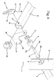
- a moving scaffold in accordance with the present invention has been generally identified with reference numeral 1.
- the moving scaffold 1 commonly referred to as cradle, is defined by a frame having a tubular metal structure and comprising at least two pairs of vertical side shoulders 2 disposed parallel to each other and having a plurality of horizontal steps or rungs 3.
- each rung is fitted into through openings obtained by cutting in the respective side shoulders 2, and fastened therein by riveting and/or welding.
- the vertical shoulders 2 therefore have holes inside which a housing 8 is formed which can be utilised for connection with further structural elements.
- Housing 8 communicates with the outside through an opening axially in alignment with the respective rung 3.
- the frame defining the moving scaffold 1 further comprises at least one pair of horizontal crosspieces 4 connecting the pairs of vertical side shoulders 2 with each other.
- a flat support surface 5 or platform which preferably rests on a pair of rungs 3 and on which the operators work.
- the frame of cradle 1 is an articulated quadrilateral; therefore the presence of at least one tie-rod or brace 6 acting as a stiffening element is required, said brace being diagonally disposed between the pairs of side shoulders 2.
- Brace 6 is connected to the side shoulders 2 at two respective rungs 3, placed at different heights, by a quick-fit mechanism 7 permanently connected to each end 6b of brace 6.
- each brace 6 has an axial extension orthogonal to the axis 6a of brace 6, and is inserted into the housing 8 of a predetermined rung 3.
- brace 6 has a through hole 13 at each of its ends 6b.
- two or more braces 6 disposed cross-wise can be present.
- Brace 6 can be a metal bar having a rectangular section Figs. 2-4 and 6 ) or a round bar ( Figs. 5 and 7 ).
- an insert 20 ( Fig. 4 ) of plastic material is positioned at the end 6b of each brace 6, which insert is adapted to fill the inner empty space at the end 6b of brace 6, making brace 6 stiffer at that exact point and being a support for it.
- brace 6 at its ends 6b is acted upon by a compression force.
- brace 6 In the second case, shown in Figs. 5 and 7 , the end 6b of brace 6 is flattened, by pressing for example. Therefore, due to the particular conformation, use of filling elements is not required.
- the quick-fit mechanism 7 comprises an elastically-deformable expandable dowel 9 to be axially fitted into housing 8 formed in the shoulder, at the rung 3 to which the brace 6 is to be connected.
- the expandable dowel 9 is connected to the end 6b of brace 6 by a pin 10 slidably inserted into the expandable dowel 9.
- Pin 10 has a flanged, i.e. enlarged, head 10b pressing the expandable dowel 9 against one side of brace 6 so as to deform it.
- Pin 10 extends along an axis 10a transverse to the longitudinal axis 6a of the respective brace 6.
- pin 10 passes through the end 6b of brace 6, inside hole 13, and has an end portion 10c, opposite to the flanged head 10b, that projects from brace 6.
- a spacer 11, slidably passed through by pin 10 is present between the expandable dowel 9 and the side of brace 6.
- the quick-fit mechanism 7 further comprises quick locking/unlocking means 12, connected to pin 10 and in particular to the end 10c of pin 10.
- the quick locking/unlocking means 12 is movable between an activation position ( Fig. 3 ) at which the expandable dowel 9 is deformed and firmly locked within housing 8, and a deactivation position ( Fig. 2 ) at which the expandable dowel 9 is in a rest position and can be disengaged from housing 8.
- the locking/unlocking means 12 comprises a lever 14 connected by a peg 23 to the end 10c of pin 10.
- Lever 14 is able to rotate around a hinge axis 15 transverse to the axis 10a of pin 10.
- lever 14 causes the axial displacement of pin 10 towards lever 14 and the consequent compression of the expandable dowel 9 between the head 10b of pin 10 and the side of brace 6.
- lever 14 has an end cam 16 that, by interfering against the side of brace 6 during rotation of lever 14, causes the simultaneous moving apart of the hinge axis 15 from said brace 6. Following this movement, lever 14 pulls pin 10 and causes axial sliding of same.
- the expandable dowel 9 compressed between the flanged head 10b of pin 10 and spacer 11, expands in the radial direction, i.e. a direction orthogonal to the axis 10a of pin 10, interfering by friction with the inner walls of housing 8.
- This swelling causes locking of mechanism 7, and particularly of the expandable dowel 9, inside the housing, and ensures a steady and permanent connection between brace 6 and the vertical shoulders 2.
- brace 6 is acted upon by compression, following rotation of lever 14 and sliding of pin 10. Therefore in case of a rectangular-section brace ( Figs. 2-6 ), it is preferred and also advantageous that the stiffening insert 20 be introduced at the end 6b, thus giving the brace 6 a structural support due to the compression caused by the expandable dowel 9 and pin 10.
- the brace of circular section ( Fig. 5 ) has a flat end 6b also provided with a hole 13.
- spacer 11 between the brace 6 and expandable dowel 9 can be advantageously present inside the quick-fit mechanism 7, to eliminate possible level differences between the various elements.
- spacer 11 placed between the expandable dowel 9 and brace 6
- a further spacer 22 is placed which is located between brace 6 and lever 14.
- each housing 8 has a perimetric enlargement 16 obtained following a riveting and/or welding operation for example, carried out during the step of securing the end of rung 3 to the respective side shoulder 2.
- the enlargement 16 creates a mechanical interference with the compressed expandable dowel 9 so as to avoid accidental disengagement of said expandable dowel 9.
- the cradle 1 can further comprise a safety device 17 maintaining the connection between the brace 6 and the vertical side shoulder 2 even when the expandable dowel 9, although inserted in housing 8, is not deformed.
- This safety device 17 comprises a suitably shaped plate hinged on the axis 10a of the mechanism 7.
- the plate comprises a U-shaped portion 18 that, under work conditions, encompasses the vertical shoulder 2 to which brace 6 is connected.
- the plate can be positioned in the work condition, following an angular rotation around its hinging axis 10a, starting from a rest condition shown in Fig. 4 at which the U-shaped portion 18 is released from the vertical shoulder 2, so as to enable transverse movement of brace 6 for insertion and extraction of the expandable dowel 9 into and from housing 8.
- Figs. 6 to 7 differ from the previously described ones due to the structure of the locking/unlocking means 12 comprising, instead of lever 14, a knob (114) connected to a corresponding end 10c of pin 10 opposite to the flanged head 10b.
- the flanged head 10b is defined by a threaded nut 115a operatively engaged on the corresponding end of pin 10 and acting against the expandable dowel 9 after interposition of a washer 115b.
- the knob 114 is adapted to be rotated about the geometric axis 10a, possibly together with pin 10, to promote axial sliding of the pin itself and consequent compression of the expandable dowel 9 between the head 10b and brace 6.
- cam devices 116 are operatively interposed between the brace 6 and knob 114 to pull pin 10 and cause axial sliding of same, following rotation of the knob around axis 10a.
- the cam devices 116 preferably comprise at least one counter-lug 119 forward projecting from the knob 114 towards the brace 6, in parallel to axis 10a.
- the counter-lug 119 operates in slidable-rest relationship on a helical projection 120 extending around axis 10a of pin 10.
- two counter-lugs 119 are present which are diametrically opposite relative to axis 10a and cooperage with respective helical projections 120 carried by an abutment plate 121 interposed between the brace 6 and knob 114 and slidably passed through by pin 10.
- the abutment plate 121 can be provided with rotation-preventing protrusions 122 acting against opposite side walls of brace 6 to avoid undesirable rotations of the plate itself around axis 10a during operation of knob 114.
- the abutment plate 121 may be provided with at least one rotation-preventing peg (not shown in the drawings) designed to be fitted into a respective hole 122a formed in the end of brace 6.
- a mere angular rotation of lever 14 or of knob 114 ensures the steady connection of the brace to the rest of the frame, without running the risk of accidental separations.
- the quick-fit mechanism is permanently connected to the brace, in such a manner that accidental losses of structural elements during the dismantling and transport steps cannot occur.
Abstract
Description
- The present invention relates to a moving scaffold.
- Moving scaffolds, more commonly referred to as "cradles", are moving structures mainly used for small building works such as plastering or painting.
- The moving scaffolds or cradles of known type are tubular structures made of aluminium or steel, having varying base sizes proportional to the height to which a work is to be made. Typically, these cradles are used for finish or servicing works at heights in the range of between 2 to 20 metres. The moving scaffold can be provided with at least one pair of wheels enabling the assembly to be moved manually and at will in the worksite.
- Cradles comprise a frame consisting of two pairs of vertical side shoulders with steps or rungs and at least one pair of horizontal crosspieces connecting the two pairs of vertical shoulders with each other.
- A stiffening element supports the articulated quadrilateral defined by the frame and prevents the structure from bending.
- The stiffening elements are tie-rods or braces for example, that are disposed cross-wise in an oblique orientation and connect the shoulders to each other.
- Finally, at least one flat support surface on which the operators stand is placed in a transverse direction relative to the side shoulders.
- In the vicinity of, or at each rung, the vertical shoulders have holes aligned with the rung axis, for connection of the tie-rods.
- In moving scaffolds of the known art, the tie-rods are tubular metal bars terminating at both ends with a slot. Each slot is able to be disposed axially superposed on said hole of the vertical shoulder, to which it is connected by a suitable fastening element. The latter can be a key or a knob with a threaded shank to maintain connection between tie-rod and vertical shoulder.
- The key is generally a metal element comprising a pivot and a suitably shaped portion. The pivot is fitted through the tie-rod slot and one of the holes provided in the shoulder. Following rotation of the key around the pivot axis, the shaped portion is coupled to the vertical shoulder preventing disengagement of the tie-rod from the rest of the structure.
- Alternatively, the fastening element can be a knob having a threaded shank to be screwed down within a threaded seat formed through the slot and the hole at the rung.
- In both solutions, the fastening element is an additional component of the scaffold with which further elements such as spacers or safety latches are to be possibly associated.
- Both the mounting and dismantling steps of the scaffold are therefore unpractical due to the presence of separated components that must be assembled to make the cradle safe.
- The smallest parts, in particular the elements of the connecting mechanism between the tie-rods and vertical shoulders can get lost more easily because they may be separated from the remainder of the frame.
- It is an object of the present invention to provide a moving scaffold or cradle that is devoid of the above described drawbacks.
- In particular, the present invention aims at proposing a cradle that can be assembled in a quick and simple manner, while at the same time ensuring high safety levels.
- It is a further aim of the invention to propose a cradle that is not equipped with individual elements of small sizes that can easily get lost.
-
Document FR 2 927 919 A1 - In accordance with the present invention a moving scaffold or cradle is provided which comprises the features present in one or more of the appended claims.
- The present invention is now described with reference to the accompanying drawings, illustrating a nonlimiting embodiment thereof, in which:
-
Fig. 1 shows a cradle in accordance with the present invention; -
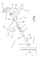
Fig. 2 shows a detail of a first embodiment of the cradle in accordance with the present invention in a first operating position; -
Fig. 2a shows a detail seen inFig. 2 , to an enlarged scale; -
Fig. 3 shows a detail of a first embodiment of the cradle in accordance with the present invention, in a second operating position; -
Fig. 3a shows a detail seen inFig. 3 , to an enlarged scale; -
Fig. 4 is an exploded view of a component shown inFigs. 2 and3 ; -
Fig. 5 is an exploded view of a component of the cradle according to the invention, in a second embodiment; -
Figs. 6 and7 are exploded views of further variants of the invention; -
Figs. 8 and9 are perspective views of two distinct components to be used in the variants shown inFigs. 6 and7 . - With reference to the drawings, a moving scaffold in accordance with the present invention has been generally identified with
reference numeral 1. - The moving
scaffold 1, commonly referred to as cradle, is defined by a frame having a tubular metal structure and comprising at least two pairs ofvertical side shoulders 2 disposed parallel to each other and having a plurality of horizontal steps orrungs 3. - The ends of each rung are fitted into through openings obtained by cutting in the
respective side shoulders 2, and fastened therein by riveting and/or welding. At eachrung 3, thevertical shoulders 2 therefore have holes inside which ahousing 8 is formed which can be utilised for connection with further structural elements. -
Housing 8 communicates with the outside through an opening axially in alignment with therespective rung 3. - The frame defining the moving
scaffold 1 further comprises at least one pair ofhorizontal crosspieces 4 connecting the pairs ofvertical side shoulders 2 with each other. - Horizontally disposed between the pairs of
side shoulders 2 is aflat support surface 5 or platform which preferably rests on a pair ofrungs 3 and on which the operators work. - The frame of
cradle 1 is an articulated quadrilateral; therefore the presence of at least one tie-rod orbrace 6 acting as a stiffening element is required, said brace being diagonally disposed between the pairs ofside shoulders 2. - Brace 6 is connected to the
side shoulders 2 at tworespective rungs 3, placed at different heights, by a quick-fit mechanism 7 permanently connected to eachend 6b ofbrace 6. - In particular, the quick-
fit mechanism 7 of each end of eachbrace 6 has an axial extension orthogonal to theaxis 6a ofbrace 6, and is inserted into thehousing 8 of apredetermined rung 3. In fact,brace 6 has a throughhole 13 at each of itsends 6b. Preferably two ormore braces 6 disposed cross-wise can be present. - Brace 6 can be a metal bar having a rectangular section
Figs. 2-4 and6 ) or a round bar (Figs. 5 and7 ). - In the first case, shown in
Figs. 2-4 and6 , an insert 20 (Fig. 4 ) of plastic material is positioned at theend 6b of eachbrace 6, which insert is adapted to fill the inner empty space at theend 6b ofbrace 6, makingbrace 6 stiffer at that exact point and being a support for it. As better explained in the following, in fact,brace 6 at itsends 6b is acted upon by a compression force. - In the second case, shown in
Figs. 5 and7 , theend 6b ofbrace 6 is flattened, by pressing for example. Therefore, due to the particular conformation, use of filling elements is not required. - The quick-
fit mechanism 7 comprises an elastically-deformableexpandable dowel 9 to be axially fitted intohousing 8 formed in the shoulder, at therung 3 to which thebrace 6 is to be connected. Theexpandable dowel 9 is connected to theend 6b ofbrace 6 by apin 10 slidably inserted into theexpandable dowel 9. -
Pin 10 has a flanged, i.e. enlarged,head 10b pressing theexpandable dowel 9 against one side ofbrace 6 so as to deform it. -
Pin 10 extends along anaxis 10a transverse to thelongitudinal axis 6a of therespective brace 6. In particular,pin 10 passes through theend 6b ofbrace 6, insidehole 13, and has anend portion 10c, opposite to the flangedhead 10b, that projects frombrace 6. - A
spacer 11, slidably passed through bypin 10 is present between theexpandable dowel 9 and the side ofbrace 6. - The quick-
fit mechanism 7 further comprises quick locking/unlocking means 12, connected topin 10 and in particular to theend 10c ofpin 10. The quick locking/unlocking means 12 is movable between an activation position (Fig. 3 ) at which theexpandable dowel 9 is deformed and firmly locked withinhousing 8, and a deactivation position (Fig. 2 ) at which theexpandable dowel 9 is in a rest position and can be disengaged fromhousing 8. - In particular, in the embodiments shown in
Figs. 1 to 5 , the locking/unlocking means 12 comprises alever 14 connected by apeg 23 to theend 10c ofpin 10.Lever 14 is able to rotate around ahinge axis 15 transverse to theaxis 10a ofpin 10. - Rotation of
lever 14 causes the axial displacement ofpin 10 towardslever 14 and the consequent compression of theexpandable dowel 9 between thehead 10b ofpin 10 and the side ofbrace 6. In fact,lever 14 has anend cam 16 that, by interfering against the side ofbrace 6 during rotation oflever 14, causes the simultaneous moving apart of thehinge axis 15 from saidbrace 6. Following this movement,lever 14 pullspin 10 and causes axial sliding of same. - In this way, the
expandable dowel 9, compressed between theflanged head 10b ofpin 10 andspacer 11, expands in the radial direction, i.e. a direction orthogonal to theaxis 10a ofpin 10, interfering by friction with the inner walls ofhousing 8. - This swelling causes locking of
mechanism 7, and particularly of theexpandable dowel 9, inside the housing, and ensures a steady and permanent connection betweenbrace 6 and thevertical shoulders 2. - The
end 6b ofbrace 6 is acted upon by compression, following rotation oflever 14 and sliding ofpin 10. Therefore in case of a rectangular-section brace (Figs. 2-6 ), it is preferred and also advantageous that the stiffeninginsert 20 be introduced at theend 6b, thus giving thebrace 6 a structural support due to the compression caused by theexpandable dowel 9 andpin 10. On the contrary, the brace of circular section (Fig. 5 ) has aflat end 6b also provided with ahole 13. - In addition to
spacer 11 between thebrace 6 andexpandable dowel 9,further spacers 22 can be advantageously present inside the quick-fit mechanism 7, to eliminate possible level differences between the various elements. For instance, when there is themechanism 7 shown inFig. 5 , in addition tospacer 11 placed between theexpandable dowel 9 andbrace 6, afurther spacer 22 is placed which is located betweenbrace 6 andlever 14. - The outer edge of each
housing 8 has aperimetric enlargement 16 obtained following a riveting and/or welding operation for example, carried out during the step of securing the end ofrung 3 to therespective side shoulder 2. Theenlargement 16 creates a mechanical interference with the compressedexpandable dowel 9 so as to avoid accidental disengagement of saidexpandable dowel 9. - The
cradle 1 can further comprise asafety device 17 maintaining the connection between thebrace 6 and thevertical side shoulder 2 even when theexpandable dowel 9, although inserted inhousing 8, is not deformed. Thissafety device 17 comprises a suitably shaped plate hinged on theaxis 10a of themechanism 7. - The plate comprises a
U-shaped portion 18 that, under work conditions, encompasses thevertical shoulder 2 to whichbrace 6 is connected. The plate can be positioned in the work condition, following an angular rotation around its hingingaxis 10a, starting from a rest condition shown inFig. 4 at which theU-shaped portion 18 is released from thevertical shoulder 2, so as to enable transverse movement ofbrace 6 for insertion and extraction of theexpandable dowel 9 into and fromhousing 8. - The embodiments shown in
Figs. 6 to 7 differ from the previously described ones due to the structure of the locking/unlockingmeans 12 comprising, instead oflever 14, a knob (114) connected to acorresponding end 10c ofpin 10 opposite to theflanged head 10b. In this case theflanged head 10b is defined by a threadednut 115a operatively engaged on the corresponding end ofpin 10 and acting against theexpandable dowel 9 after interposition of awasher 115b. - The
knob 114 is adapted to be rotated about thegeometric axis 10a, possibly together withpin 10, to promote axial sliding of the pin itself and consequent compression of theexpandable dowel 9 between the head 10b andbrace 6. - To this
aim cam devices 116 are operatively interposed between thebrace 6 andknob 114 to pullpin 10 and cause axial sliding of same, following rotation of the knob aroundaxis 10a. Thecam devices 116 preferably comprise at least one counter-lug 119 forward projecting from theknob 114 towards thebrace 6, in parallel toaxis 10a. The counter-lug 119 operates in slidable-rest relationship on ahelical projection 120 extending aroundaxis 10a ofpin 10. In the example shown, twocounter-lugs 119 are present which are diametrically opposite relative toaxis 10a and cooperage with respectivehelical projections 120 carried by anabutment plate 121 interposed between thebrace 6 andknob 114 and slidably passed through bypin 10. Theabutment plate 121 can be provided with rotation-preventingprotrusions 122 acting against opposite side walls ofbrace 6 to avoid undesirable rotations of the plate itself aroundaxis 10a during operation ofknob 114. In addition to or in place of the rotation-preventingprotrusions 122, theabutment plate 121 may be provided with at least one rotation-preventing peg (not shown in the drawings) designed to be fitted into arespective hole 122a formed in the end ofbrace 6. - Mounting and dismantling of
cradle 1 appears to be quick and braces 6 are firmly connected to the rest of the frame by means of the described quick-fit mechanism. - A mere angular rotation of
lever 14 or ofknob 114 ensures the steady connection of the brace to the rest of the frame, without running the risk of accidental separations. - The quick-fit mechanism is permanently connected to the brace, in such a manner that accidental losses of structural elements during the dismantling and transport steps cannot occur.
Claims (15)
- A cradle or moving scaffold comprising a frame defined by at least two pairs of vertical side shoulders (2) disposed parallel to each other, each pair having a plurality of rungs (3), at least one flat support surface for workmen (5) located transversely between the pairs of side shoulders (2) and at least one brace (6) diagonally disposed between the pairs of side shoulders (2), wherein said brace (6) is connected to said side shoulders (2) by a quick-fit mechanism (7) permanently connected to each end of each brace (6), wherein said side shoulders (2) have housings (8) communicating with the outside, characterised in that said quick-fit mechanism (7) comprises:- an elastically-deformable expandable dowel (9), to be axially inserted into one of said housings.
- A cradle as claimed in claim 1, wherein said quick-fit mechanism (7) comprises a pin (10) slidably inserted into said expandable dowel (9), said pin (10) having a flanged head (10b) axially compressing the expandable dowel (9) for radially expanding it.
- A cradle as claimed in claim 2, wherein said pin (10) extends along an axis (10a) transverse to the longitudinal axis (6a) of the respective brace (6).
- A cradle as claimed in claim 2 or 3, wherein said expandable dowel (9) is compressible between the flanged head (10b) of said pin (10) and one side of said brace (6).
- A cradle as claimed in one or more of claims 2 to 4, wherein said quick-fit mechanism (7) comprises quick locking/unlocking means (7) connected to said pin (10) and movable between an activation position, at which the expandable dowel (9) is deformed and firmly locked inside the housing (8), and a deactivation position, at which the expandable dowel is in a rest position and can be released from the housing (8).
- A cradle as claimed in one or more of claims 2 to 5, wherein said quick-fit mechanism (7) comprises a lever connected to one end (10c) of said pin (10) opposite to the flanged head (10b); said lever (14) being rotatable about a hinge axis (15) transverse to an axis (10a) of the pin (10) for promoting axial sliding of said pin and the consequent compression of said expandable dowel (9) between the head (10b) of the pin (10) and the brace (6).
- A cradle as claimed in claim 6, wherein said lever (14) is disposed on the opposite side of said expandable dowel (9) relative to the brace (6); said lever (14) having a cam end (16) that, following rotation of the lever around the hinge axis (15), pulls the pin (10) and causes axial sliding of same.
- A cradle as claimed in one or more of claims 2 to 5, wherein said quick-fit mechanism (7) comprises a knob (114) connected to one end (10c) of said pin (10) opposite to the flanged head (10b); said knob (114) being rotatable about the axis (10a) of the pin (10) to promote axial sliding of said pin and consequent compression of said expandable dowel (9) between the head (10b) of the pin (10) and the brace (6).
- A cradle as claimed in claim 8, wherein said knob (114) is disposed on the opposite side of said expandable dowel (9) relative to the brace (6); cam devices (116) being operatively interposed between the brace (6) and said knob (114) to pull the pin (10) and cause axial sliding of same, following rotation of the knob around the axis (10a) of the pin (10).
- A cradle as claimed in claim 9, wherein said cam devices (116) comprise at least one counter-lug (119) slidable on a helical projection (120) extending around the axis (10a) of the pin (10), one of which is integral with the knob (114) while the other is carried by an abutment plate (121) interposed between the brace (6) and the knob (114).
- A cradle as claimed in one or more of claims 2 to 9, wherein said mechanism (7) further comprises at least one spacer (11) slidably passed through by the pin (10) and axially interposed between the expandable dowel (9) and the brace (6) .
- A cradle as claimed in one or more of the preceding claims, wherein said mechanism (7) further comprises a safety device (17) ensuring connection between the brace (6) and the vertical side shoulder (2), wherein said safety device (17) comprises a shaped plate, hinged on the brace and having a U-shaped portion (18) encompassing the vertical shoulder (2) to which the brace (6) is connected.
- A cradle as claimed in one or more of the preceding claims, wherein said housing (8) on an outer edge thereof has an enlargement (16) creating a mechanical interference with the expandable dowel (9) in the deformed configuration, to prevent the occurrence of an accidental disengagement of the expandable dowel (9) from the respective housing (8).
- A cradle as claimed in one or more of the preceding claims, wherein said at least one brace has a tubular section with flattened ends, each carrying said quick-fit mechanism (7).
- A cradle as claimed in one or more of the preceding claims, wherein said quick-fit mechanism (7) comprises at least one end insert (20) filling the empty end (6b) of the brace (6) of tubular section, to counteract compression stresses imposed to the end of the brace.
Priority Applications (1)
| Application Number | Priority Date | Filing Date | Title |
|---|---|---|---|
| EP10167640A EP2314797B1 (en) | 2009-10-22 | 2010-06-29 | Moving scaffold |
Applications Claiming Priority (2)
| Application Number | Priority Date | Filing Date | Title |
|---|---|---|---|
| EP09425419A EP2314796A1 (en) | 2009-10-22 | 2009-10-22 | Cradle |
| EP10167640A EP2314797B1 (en) | 2009-10-22 | 2010-06-29 | Moving scaffold |
Publications (2)
| Publication Number | Publication Date |
|---|---|
| EP2314797A1 true EP2314797A1 (en) | 2011-04-27 |
| EP2314797B1 EP2314797B1 (en) | 2012-01-04 |
Family
ID=41719344
Family Applications (2)
| Application Number | Title | Priority Date | Filing Date |
|---|---|---|---|
| EP09425419A Withdrawn EP2314796A1 (en) | 2009-10-22 | 2009-10-22 | Cradle |
| EP10167640A Not-in-force EP2314797B1 (en) | 2009-10-22 | 2010-06-29 | Moving scaffold |
Family Applications Before (1)
| Application Number | Title | Priority Date | Filing Date |
|---|---|---|---|
| EP09425419A Withdrawn EP2314796A1 (en) | 2009-10-22 | 2009-10-22 | Cradle |
Country Status (2)
| Country | Link |
|---|---|
| EP (2) | EP2314796A1 (en) |
| AT (1) | ATE540179T1 (en) |
Cited By (2)
| Publication number | Priority date | Publication date | Assignee | Title |
|---|---|---|---|---|
| FR3070701A1 (en) * | 2017-09-06 | 2019-03-08 | Cdh Group | SYSTEM FOR FASTENING A STIFFENER AND / OR A GUARD RAIL TO A SCAFFOLDING CAPABLE OF FACILITATING ACCESS TO A SCAFFOLD FLOOR |
| CN110145110A (en) * | 2019-05-10 | 2019-08-20 | 中国三冶集团有限公司 | One discharge plate buckle type scaffold |
Families Citing this family (2)
| Publication number | Priority date | Publication date | Assignee | Title |
|---|---|---|---|---|
| FR3068375B1 (en) * | 2017-06-28 | 2021-10-08 | Cdh Group | DEVICE FOR FIXING A REINFORCEMENT PART ON A SCAFFOLDING, SCAFFOLDING EQUIPPED WITH SUCH A DEVICE |
| EP4098892A1 (en) * | 2021-05-31 | 2022-12-07 | Dedalo Tech Societa' a Responsabilita' Limitata Semplificata | Locking pin for scaffolding structures |
Citations (5)
| Publication number | Priority date | Publication date | Assignee | Title |
|---|---|---|---|---|
| FR1568237A (en) * | 1968-03-11 | 1969-05-23 | ||
| DE1559006A1 (en) * | 1965-06-30 | 1969-08-21 | Juculano Theodore Charles | Device for easily detachable connection of the uprights and fillers of scaffolding |
| DE10245743A1 (en) * | 2002-10-01 | 2004-04-15 | Peri Gmbh | Collapsible frame has horizontal beams with projections at ends with hook elements engaging in opening of vertical post for connection |
| EP1686221A2 (en) * | 2004-12-29 | 2006-08-02 | Centaure | Connecting device for parts of a scaffold |
| FR2927919A1 (en) | 2008-02-25 | 2009-08-28 | Centaure Sa | Scaffolding element e.g. diagonal brace, for constructing temporary, fixed or mobile stile, has mounting core whose external surface has sliding ramps forming continuity between angular sectors of proximal and distal transversal sections |
-
2009
- 2009-10-22 EP EP09425419A patent/EP2314796A1/en not_active Withdrawn
-
2010
- 2010-06-29 AT AT10167640T patent/ATE540179T1/en active
- 2010-06-29 EP EP10167640A patent/EP2314797B1/en not_active Not-in-force
Patent Citations (5)
| Publication number | Priority date | Publication date | Assignee | Title |
|---|---|---|---|---|
| DE1559006A1 (en) * | 1965-06-30 | 1969-08-21 | Juculano Theodore Charles | Device for easily detachable connection of the uprights and fillers of scaffolding |
| FR1568237A (en) * | 1968-03-11 | 1969-05-23 | ||
| DE10245743A1 (en) * | 2002-10-01 | 2004-04-15 | Peri Gmbh | Collapsible frame has horizontal beams with projections at ends with hook elements engaging in opening of vertical post for connection |
| EP1686221A2 (en) * | 2004-12-29 | 2006-08-02 | Centaure | Connecting device for parts of a scaffold |
| FR2927919A1 (en) | 2008-02-25 | 2009-08-28 | Centaure Sa | Scaffolding element e.g. diagonal brace, for constructing temporary, fixed or mobile stile, has mounting core whose external surface has sliding ramps forming continuity between angular sectors of proximal and distal transversal sections |
Cited By (2)
| Publication number | Priority date | Publication date | Assignee | Title |
|---|---|---|---|---|
| FR3070701A1 (en) * | 2017-09-06 | 2019-03-08 | Cdh Group | SYSTEM FOR FASTENING A STIFFENER AND / OR A GUARD RAIL TO A SCAFFOLDING CAPABLE OF FACILITATING ACCESS TO A SCAFFOLD FLOOR |
| CN110145110A (en) * | 2019-05-10 | 2019-08-20 | 中国三冶集团有限公司 | One discharge plate buckle type scaffold |
Also Published As
| Publication number | Publication date |
|---|---|
| EP2314797B1 (en) | 2012-01-04 |
| EP2314796A1 (en) | 2011-04-27 |
| ATE540179T1 (en) | 2012-01-15 |
Similar Documents
| Publication | Publication Date | Title |
|---|---|---|
| EP2314797B1 (en) | Moving scaffold | |
| JP6305523B2 (en) | Platform unit for use with scaffold structure | |
| EP3015623B1 (en) | Method and apparatus for assembly of a shoring tower | |
| US5112155A (en) | Connector for assembling components of scaffolding | |
| MX2013008244A (en) | Scaffold apparatus, method and system. | |
| EP3492688B1 (en) | Arrangement introduced in a device having a hook for anchoring a ladder to cables | |
| CN117627520A (en) | Ladder hinge and ladder incorporating same | |
| US8794381B2 (en) | Fittings for builders' trestles | |
| KR20190107726A (en) | Connector for temporary scaffold | |
| KR20180046603A (en) | Holding member for scaffold and scaffold using it | |
| EP1650377B1 (en) | Side closure for facade scaffolding | |
| WO2006086989A1 (en) | Safety lock for scaffolding | |
| GB2415225A (en) | Kickboard bracket and telescopic rail for builders' trestle | |
| US20220010569A1 (en) | Scaffolding post connection rosette with hollow embossments of reduced nominal thickness, and scaffolding subassembly | |
| KR102034405B1 (en) | Safety Scaffold for Falling Preventing | |
| JP5574208B1 (en) | Brace upper mounting bracket | |
| WO1988003212A1 (en) | Scaffolding system | |
| EP3336279A1 (en) | Mobile scaffolding | |
| JP2017036624A (en) | Extendable leg device | |
| EP2808464A1 (en) | Scaffolding tower assembly and method for erecting scaffolding tower | |
| WO2000034601A1 (en) | A scaffolding arrangement with a rotatable cam for lowering a load bearing element | |
| US9677291B2 (en) | Turnbuckle clip for use with concrete forming products | |
| JP3160446U (en) | Scaffolding board | |
| JP5292496B2 (en) | Scaffolding board | |
| CN219158344U (en) | Assembly comprising a folding ladder and a platform |
Legal Events
| Date | Code | Title | Description |
|---|---|---|---|
| PUAI | Public reference made under article 153(3) epc to a published international application that has entered the european phase |
Free format text: ORIGINAL CODE: 0009012 |
|
| 17P | Request for examination filed |
Effective date: 20101129 |
|
| AK | Designated contracting states |
Kind code of ref document: A1 Designated state(s): AL AT BE BG CH CY CZ DE DK EE ES FI FR GB GR HR HU IE IS IT LI LT LU LV MC MK MT NL NO PL PT RO SE SI SK SM TR |
|
| AX | Request for extension of the european patent |
Extension state: BA ME RS |
|
| GRAP | Despatch of communication of intention to grant a patent |
Free format text: ORIGINAL CODE: EPIDOSNIGR1 |
|
| RIC1 | Information provided on ipc code assigned before grant |
Ipc: E04G 5/16 20060101ALI20110728BHEP Ipc: E04G 7/30 20060101AFI20110728BHEP |
|
| GRAS | Grant fee paid |
Free format text: ORIGINAL CODE: EPIDOSNIGR3 |
|
| GRAA | (expected) grant |
Free format text: ORIGINAL CODE: 0009210 |
|
| AK | Designated contracting states |
Kind code of ref document: B1 Designated state(s): AL AT BE BG CH CY CZ DE DK EE ES FI FR GB GR HR HU IE IS IT LI LT LU LV MC MK MT NL NO PL PT RO SE SI SK SM TR |
|
| REG | Reference to a national code |
Ref country code: GB Ref legal event code: FG4D |
|
| REG | Reference to a national code |
Ref country code: CH Ref legal event code: EP |
|
| REG | Reference to a national code |
Ref country code: AT Ref legal event code: REF Ref document number: 540179 Country of ref document: AT Kind code of ref document: T Effective date: 20120115 |
|
| REG | Reference to a national code |
Ref country code: IE Ref legal event code: FG4D |
|
| REG | Reference to a national code |
Ref country code: DE Ref legal event code: R096 Ref document number: 602010000622 Country of ref document: DE Effective date: 20120308 |
|
| REG | Reference to a national code |
Ref country code: NL Ref legal event code: VDEP Effective date: 20120104 |
|
| PG25 | Lapsed in a contracting state [announced via postgrant information from national office to epo] |
Ref country code: SI Free format text: LAPSE BECAUSE OF FAILURE TO SUBMIT A TRANSLATION OF THE DESCRIPTION OR TO PAY THE FEE WITHIN THE PRESCRIBED TIME-LIMIT Effective date: 20120104 |
|
| LTIE | Lt: invalidation of european patent or patent extension |
Effective date: 20120104 |
|
| PG25 | Lapsed in a contracting state [announced via postgrant information from national office to epo] |
Ref country code: BG Free format text: LAPSE BECAUSE OF FAILURE TO SUBMIT A TRANSLATION OF THE DESCRIPTION OR TO PAY THE FEE WITHIN THE PRESCRIBED TIME-LIMIT Effective date: 20120404 Ref country code: NL Free format text: LAPSE BECAUSE OF FAILURE TO SUBMIT A TRANSLATION OF THE DESCRIPTION OR TO PAY THE FEE WITHIN THE PRESCRIBED TIME-LIMIT Effective date: 20120104 Ref country code: HR Free format text: LAPSE BECAUSE OF FAILURE TO SUBMIT A TRANSLATION OF THE DESCRIPTION OR TO PAY THE FEE WITHIN THE PRESCRIBED TIME-LIMIT Effective date: 20120104 Ref country code: BE Free format text: LAPSE BECAUSE OF FAILURE TO SUBMIT A TRANSLATION OF THE DESCRIPTION OR TO PAY THE FEE WITHIN THE PRESCRIBED TIME-LIMIT Effective date: 20120104 Ref country code: LT Free format text: LAPSE BECAUSE OF FAILURE TO SUBMIT A TRANSLATION OF THE DESCRIPTION OR TO PAY THE FEE WITHIN THE PRESCRIBED TIME-LIMIT Effective date: 20120104 Ref country code: NO Free format text: LAPSE BECAUSE OF FAILURE TO SUBMIT A TRANSLATION OF THE DESCRIPTION OR TO PAY THE FEE WITHIN THE PRESCRIBED TIME-LIMIT Effective date: 20120404 Ref country code: IS Free format text: LAPSE BECAUSE OF FAILURE TO SUBMIT A TRANSLATION OF THE DESCRIPTION OR TO PAY THE FEE WITHIN THE PRESCRIBED TIME-LIMIT Effective date: 20120504 |
|
| PG25 | Lapsed in a contracting state [announced via postgrant information from national office to epo] |
Ref country code: LV Free format text: LAPSE BECAUSE OF FAILURE TO SUBMIT A TRANSLATION OF THE DESCRIPTION OR TO PAY THE FEE WITHIN THE PRESCRIBED TIME-LIMIT Effective date: 20120104 Ref country code: PL Free format text: LAPSE BECAUSE OF FAILURE TO SUBMIT A TRANSLATION OF THE DESCRIPTION OR TO PAY THE FEE WITHIN THE PRESCRIBED TIME-LIMIT Effective date: 20120104 Ref country code: PT Free format text: LAPSE BECAUSE OF FAILURE TO SUBMIT A TRANSLATION OF THE DESCRIPTION OR TO PAY THE FEE WITHIN THE PRESCRIBED TIME-LIMIT Effective date: 20120504 Ref country code: FI Free format text: LAPSE BECAUSE OF FAILURE TO SUBMIT A TRANSLATION OF THE DESCRIPTION OR TO PAY THE FEE WITHIN THE PRESCRIBED TIME-LIMIT Effective date: 20120104 Ref country code: GR Free format text: LAPSE BECAUSE OF FAILURE TO SUBMIT A TRANSLATION OF THE DESCRIPTION OR TO PAY THE FEE WITHIN THE PRESCRIBED TIME-LIMIT Effective date: 20120405 |
|
| REG | Reference to a national code |
Ref country code: AT Ref legal event code: MK05 Ref document number: 540179 Country of ref document: AT Kind code of ref document: T Effective date: 20120104 |
|
| PG25 | Lapsed in a contracting state [announced via postgrant information from national office to epo] |
Ref country code: CY Free format text: LAPSE BECAUSE OF FAILURE TO SUBMIT A TRANSLATION OF THE DESCRIPTION OR TO PAY THE FEE WITHIN THE PRESCRIBED TIME-LIMIT Effective date: 20120104 |
|
| PG25 | Lapsed in a contracting state [announced via postgrant information from national office to epo] |
Ref country code: EE Free format text: LAPSE BECAUSE OF FAILURE TO SUBMIT A TRANSLATION OF THE DESCRIPTION OR TO PAY THE FEE WITHIN THE PRESCRIBED TIME-LIMIT Effective date: 20120104 Ref country code: RO Free format text: LAPSE BECAUSE OF FAILURE TO SUBMIT A TRANSLATION OF THE DESCRIPTION OR TO PAY THE FEE WITHIN THE PRESCRIBED TIME-LIMIT Effective date: 20120104 Ref country code: SE Free format text: LAPSE BECAUSE OF FAILURE TO SUBMIT A TRANSLATION OF THE DESCRIPTION OR TO PAY THE FEE WITHIN THE PRESCRIBED TIME-LIMIT Effective date: 20120104 Ref country code: DK Free format text: LAPSE BECAUSE OF FAILURE TO SUBMIT A TRANSLATION OF THE DESCRIPTION OR TO PAY THE FEE WITHIN THE PRESCRIBED TIME-LIMIT Effective date: 20120104 Ref country code: CZ Free format text: LAPSE BECAUSE OF FAILURE TO SUBMIT A TRANSLATION OF THE DESCRIPTION OR TO PAY THE FEE WITHIN THE PRESCRIBED TIME-LIMIT Effective date: 20120104 |
|
| PLBE | No opposition filed within time limit |
Free format text: ORIGINAL CODE: 0009261 |
|
| STAA | Information on the status of an ep patent application or granted ep patent |
Free format text: STATUS: NO OPPOSITION FILED WITHIN TIME LIMIT |
|
| PG25 | Lapsed in a contracting state [announced via postgrant information from national office to epo] |
Ref country code: SK Free format text: LAPSE BECAUSE OF FAILURE TO SUBMIT A TRANSLATION OF THE DESCRIPTION OR TO PAY THE FEE WITHIN THE PRESCRIBED TIME-LIMIT Effective date: 20120104 |
|
| 26N | No opposition filed |
Effective date: 20121005 |
|
| PG25 | Lapsed in a contracting state [announced via postgrant information from national office to epo] |
Ref country code: AT Free format text: LAPSE BECAUSE OF FAILURE TO SUBMIT A TRANSLATION OF THE DESCRIPTION OR TO PAY THE FEE WITHIN THE PRESCRIBED TIME-LIMIT Effective date: 20120104 Ref country code: MC Free format text: LAPSE BECAUSE OF NON-PAYMENT OF DUE FEES Effective date: 20120630 |
|
| REG | Reference to a national code |
Ref country code: DE Ref legal event code: R097 Ref document number: 602010000622 Country of ref document: DE Effective date: 20121005 |
|
| PG25 | Lapsed in a contracting state [announced via postgrant information from national office to epo] |
Ref country code: MK Free format text: LAPSE BECAUSE OF FAILURE TO SUBMIT A TRANSLATION OF THE DESCRIPTION OR TO PAY THE FEE WITHIN THE PRESCRIBED TIME-LIMIT Effective date: 20120104 |
|
| REG | Reference to a national code |
Ref country code: IE Ref legal event code: MM4A |
|
| PG25 | Lapsed in a contracting state [announced via postgrant information from national office to epo] |
Ref country code: IE Free format text: LAPSE BECAUSE OF NON-PAYMENT OF DUE FEES Effective date: 20120629 Ref country code: ES Free format text: LAPSE BECAUSE OF FAILURE TO SUBMIT A TRANSLATION OF THE DESCRIPTION OR TO PAY THE FEE WITHIN THE PRESCRIBED TIME-LIMIT Effective date: 20120415 |
|
| PG25 | Lapsed in a contracting state [announced via postgrant information from national office to epo] |
Ref country code: MT Free format text: LAPSE BECAUSE OF FAILURE TO SUBMIT A TRANSLATION OF THE DESCRIPTION OR TO PAY THE FEE WITHIN THE PRESCRIBED TIME-LIMIT Effective date: 20120104 |
|
| PG25 | Lapsed in a contracting state [announced via postgrant information from national office to epo] |
Ref country code: AL Free format text: LAPSE BECAUSE OF FAILURE TO SUBMIT A TRANSLATION OF THE DESCRIPTION OR TO PAY THE FEE WITHIN THE PRESCRIBED TIME-LIMIT Effective date: 20120104 |
|
| PG25 | Lapsed in a contracting state [announced via postgrant information from national office to epo] |
Ref country code: TR Free format text: LAPSE BECAUSE OF FAILURE TO SUBMIT A TRANSLATION OF THE DESCRIPTION OR TO PAY THE FEE WITHIN THE PRESCRIBED TIME-LIMIT Effective date: 20120104 |
|
| PG25 | Lapsed in a contracting state [announced via postgrant information from national office to epo] |
Ref country code: LU Free format text: LAPSE BECAUSE OF NON-PAYMENT OF DUE FEES Effective date: 20120629 Ref country code: SM Free format text: LAPSE BECAUSE OF FAILURE TO SUBMIT A TRANSLATION OF THE DESCRIPTION OR TO PAY THE FEE WITHIN THE PRESCRIBED TIME-LIMIT Effective date: 20120104 |
|
| PG25 | Lapsed in a contracting state [announced via postgrant information from national office to epo] |
Ref country code: HU Free format text: LAPSE BECAUSE OF FAILURE TO SUBMIT A TRANSLATION OF THE DESCRIPTION OR TO PAY THE FEE WITHIN THE PRESCRIBED TIME-LIMIT Effective date: 20100629 |
|
| REG | Reference to a national code |
Ref country code: CH Ref legal event code: PL |
|
| GBPC | Gb: european patent ceased through non-payment of renewal fee |
Effective date: 20140629 |
|
| PG25 | Lapsed in a contracting state [announced via postgrant information from national office to epo] |
Ref country code: LI Free format text: LAPSE BECAUSE OF NON-PAYMENT OF DUE FEES Effective date: 20140630 Ref country code: CH Free format text: LAPSE BECAUSE OF NON-PAYMENT OF DUE FEES Effective date: 20140630 |
|
| PG25 | Lapsed in a contracting state [announced via postgrant information from national office to epo] |
Ref country code: GB Free format text: LAPSE BECAUSE OF NON-PAYMENT OF DUE FEES Effective date: 20140629 |
|
| REG | Reference to a national code |
Ref country code: FR Ref legal event code: PLFP Year of fee payment: 7 |
|
| PGFP | Annual fee paid to national office [announced via postgrant information from national office to epo] |
Ref country code: FR Payment date: 20160630 Year of fee payment: 7 |
|
| PGFP | Annual fee paid to national office [announced via postgrant information from national office to epo] |
Ref country code: DE Payment date: 20160831 Year of fee payment: 7 Ref country code: IT Payment date: 20160622 Year of fee payment: 7 |
|
| REG | Reference to a national code |
Ref country code: DE Ref legal event code: R119 Ref document number: 602010000622 Country of ref document: DE |
|
| REG | Reference to a national code |
Ref country code: FR Ref legal event code: ST Effective date: 20180228 |
|
| PG25 | Lapsed in a contracting state [announced via postgrant information from national office to epo] |
Ref country code: DE Free format text: LAPSE BECAUSE OF NON-PAYMENT OF DUE FEES Effective date: 20180103 |
|
| PG25 | Lapsed in a contracting state [announced via postgrant information from national office to epo] |
Ref country code: FR Free format text: LAPSE BECAUSE OF NON-PAYMENT OF DUE FEES Effective date: 20170630 Ref country code: IT Free format text: LAPSE BECAUSE OF NON-PAYMENT OF DUE FEES Effective date: 20170629 |