EP2314399A1 - Method for treating surface of casting mold and casting mold using same - Google Patents
Method for treating surface of casting mold and casting mold using same Download PDFInfo
- Publication number
- EP2314399A1 EP2314399A1 EP09803012A EP09803012A EP2314399A1 EP 2314399 A1 EP2314399 A1 EP 2314399A1 EP 09803012 A EP09803012 A EP 09803012A EP 09803012 A EP09803012 A EP 09803012A EP 2314399 A1 EP2314399 A1 EP 2314399A1
- Authority
- EP
- European Patent Office
- Prior art keywords
- carbon
- casting mold
- film
- fullerenes
- mold
- Prior art date
- Legal status (The legal status is an assumption and is not a legal conclusion. Google has not performed a legal analysis and makes no representation as to the accuracy of the status listed.)
- Granted
Links
- 238000005266 casting Methods 0.000 title claims abstract description 66
- 238000000034 method Methods 0.000 title claims abstract description 58
- OKTJSMMVPCPJKN-UHFFFAOYSA-N Carbon Chemical compound [C] OKTJSMMVPCPJKN-UHFFFAOYSA-N 0.000 claims abstract description 67
- XMWRBQBLMFGWIX-UHFFFAOYSA-N C60 fullerene Chemical class C12=C3C(C4=C56)=C7C8=C5C5=C9C%10=C6C6=C4C1=C1C4=C6C6=C%10C%10=C9C9=C%11C5=C8C5=C8C7=C3C3=C7C2=C1C1=C2C4=C6C4=C%10C6=C9C9=C%11C5=C5C8=C3C3=C7C1=C1C2=C4C6=C2C9=C5C3=C12 XMWRBQBLMFGWIX-UHFFFAOYSA-N 0.000 claims abstract description 65
- 229910052799 carbon Inorganic materials 0.000 claims abstract description 59
- 229910003472 fullerene Inorganic materials 0.000 claims abstract description 57
- 229910021392 nanocarbon Inorganic materials 0.000 claims abstract description 54
- 238000004381 surface treatment Methods 0.000 claims abstract description 30
- 239000011203 carbon fibre reinforced carbon Substances 0.000 claims abstract description 8
- 229910021393 carbon nanotube Inorganic materials 0.000 claims abstract description 8
- 239000002041 carbon nanotube Substances 0.000 claims abstract description 8
- 229910052782 aluminium Inorganic materials 0.000 abstract description 18
- XAGFODPZIPBFFR-UHFFFAOYSA-N aluminium Chemical compound [Al] XAGFODPZIPBFFR-UHFFFAOYSA-N 0.000 abstract description 18
- 239000000463 material Substances 0.000 abstract description 11
- 238000012360 testing method Methods 0.000 description 46
- 230000000052 comparative effect Effects 0.000 description 35
- 230000003578 releasing effect Effects 0.000 description 15
- 238000004512 die casting Methods 0.000 description 13
- 238000000465 moulding Methods 0.000 description 12
- 238000005259 measurement Methods 0.000 description 11
- 229910052751 metal Inorganic materials 0.000 description 10
- 239000002184 metal Substances 0.000 description 10
- 239000007789 gas Substances 0.000 description 6
- 238000001878 scanning electron micrograph Methods 0.000 description 6
- QGZKDVFQNNGYKY-UHFFFAOYSA-N Ammonia Chemical compound N QGZKDVFQNNGYKY-UHFFFAOYSA-N 0.000 description 5
- 239000000314 lubricant Substances 0.000 description 5
- 238000012423 maintenance Methods 0.000 description 4
- 238000004519 manufacturing process Methods 0.000 description 4
- 229910000838 Al alloy Inorganic materials 0.000 description 3
- HSFWRNGVRCDJHI-UHFFFAOYSA-N alpha-acetylene Natural products C#C HSFWRNGVRCDJHI-UHFFFAOYSA-N 0.000 description 3
- 239000004744 fabric Substances 0.000 description 3
- IJGRMHOSHXDMSA-UHFFFAOYSA-N Atomic nitrogen Chemical compound N#N IJGRMHOSHXDMSA-UHFFFAOYSA-N 0.000 description 2
- RWSOTUBLDIXVET-UHFFFAOYSA-N Dihydrogen sulfide Chemical compound S RWSOTUBLDIXVET-UHFFFAOYSA-N 0.000 description 2
- XEEYBQQBJWHFJM-UHFFFAOYSA-N Iron Chemical compound [Fe] XEEYBQQBJWHFJM-UHFFFAOYSA-N 0.000 description 2
- XUIMIQQOPSSXEZ-UHFFFAOYSA-N Silicon Chemical compound [Si] XUIMIQQOPSSXEZ-UHFFFAOYSA-N 0.000 description 2
- 229910000831 Steel Inorganic materials 0.000 description 2
- 150000001721 carbon Chemical class 0.000 description 2
- 125000004432 carbon atom Chemical group C* 0.000 description 2
- 229910001873 dinitrogen Inorganic materials 0.000 description 2
- 239000000839 emulsion Substances 0.000 description 2
- 125000002534 ethynyl group Chemical group [H]C#C* 0.000 description 2
- 238000010438 heat treatment Methods 0.000 description 2
- 150000004767 nitrides Chemical class 0.000 description 2
- 239000000843 powder Substances 0.000 description 2
- 229910052710 silicon Inorganic materials 0.000 description 2
- 239000010703 silicon Substances 0.000 description 2
- 239000010959 steel Substances 0.000 description 2
- 229910001315 Tool steel Inorganic materials 0.000 description 1
- 229910045601 alloy Inorganic materials 0.000 description 1
- 239000000956 alloy Substances 0.000 description 1
- 229910021529 ammonia Inorganic materials 0.000 description 1
- 239000003575 carbonaceous material Substances 0.000 description 1
- 238000001816 cooling Methods 0.000 description 1
- 238000005516 engineering process Methods 0.000 description 1
- 125000000524 functional group Chemical group 0.000 description 1
- 229910000037 hydrogen sulfide Inorganic materials 0.000 description 1
- 238000002347 injection Methods 0.000 description 1
- 239000007924 injection Substances 0.000 description 1
- 229910052742 iron Inorganic materials 0.000 description 1
- 230000002045 lasting effect Effects 0.000 description 1
- 239000000203 mixture Substances 0.000 description 1
- 238000012986 modification Methods 0.000 description 1
- 230000004048 modification Effects 0.000 description 1
- 239000012299 nitrogen atmosphere Substances 0.000 description 1
- 229910000069 nitrogen hydride Inorganic materials 0.000 description 1
- 238000003825 pressing Methods 0.000 description 1
- 239000012495 reaction gas Substances 0.000 description 1
- 230000000717 retained effect Effects 0.000 description 1
- 239000000243 solution Substances 0.000 description 1
- 239000000126 substance Substances 0.000 description 1
Images


Classifications
-
- B—PERFORMING OPERATIONS; TRANSPORTING
- B22—CASTING; POWDER METALLURGY
- B22C—FOUNDRY MOULDING
- B22C9/00—Moulds or cores; Moulding processes
- B22C9/06—Permanent moulds for shaped castings
-
- B—PERFORMING OPERATIONS; TRANSPORTING
- B22—CASTING; POWDER METALLURGY
- B22C—FOUNDRY MOULDING
- B22C3/00—Selection of compositions for coating the surfaces of moulds, cores, or patterns
-
- B—PERFORMING OPERATIONS; TRANSPORTING
- B22—CASTING; POWDER METALLURGY
- B22D—CASTING OF METALS; CASTING OF OTHER SUBSTANCES BY THE SAME PROCESSES OR DEVICES
- B22D17/00—Pressure die casting or injection die casting, i.e. casting in which the metal is forced into a mould under high pressure
- B22D17/20—Accessories: Details
- B22D17/2007—Methods or apparatus for cleaning or lubricating moulds
-
- C—CHEMISTRY; METALLURGY
- C01—INORGANIC CHEMISTRY
- C01B—NON-METALLIC ELEMENTS; COMPOUNDS THEREOF; METALLOIDS OR COMPOUNDS THEREOF NOT COVERED BY SUBCLASS C01C
- C01B32/00—Carbon; Compounds thereof
- C01B32/15—Nano-sized carbon materials
-
- C—CHEMISTRY; METALLURGY
- C01—INORGANIC CHEMISTRY
- C01B—NON-METALLIC ELEMENTS; COMPOUNDS THEREOF; METALLOIDS OR COMPOUNDS THEREOF NOT COVERED BY SUBCLASS C01C
- C01B32/00—Carbon; Compounds thereof
- C01B32/15—Nano-sized carbon materials
- C01B32/152—Fullerenes
-
- C—CHEMISTRY; METALLURGY
- C23—COATING METALLIC MATERIAL; COATING MATERIAL WITH METALLIC MATERIAL; CHEMICAL SURFACE TREATMENT; DIFFUSION TREATMENT OF METALLIC MATERIAL; COATING BY VACUUM EVAPORATION, BY SPUTTERING, BY ION IMPLANTATION OR BY CHEMICAL VAPOUR DEPOSITION, IN GENERAL; INHIBITING CORROSION OF METALLIC MATERIAL OR INCRUSTATION IN GENERAL
- C23C—COATING METALLIC MATERIAL; COATING MATERIAL WITH METALLIC MATERIAL; SURFACE TREATMENT OF METALLIC MATERIAL BY DIFFUSION INTO THE SURFACE, BY CHEMICAL CONVERSION OR SUBSTITUTION; COATING BY VACUUM EVAPORATION, BY SPUTTERING, BY ION IMPLANTATION OR BY CHEMICAL VAPOUR DEPOSITION, IN GENERAL
- C23C24/00—Coating starting from inorganic powder
- C23C24/08—Coating starting from inorganic powder by application of heat or pressure and heat
- C23C24/082—Coating starting from inorganic powder by application of heat or pressure and heat without intermediate formation of a liquid in the layer
Abstract
Description
- The present invention relates to a casting mold surface treatment method, and a casting mold having a carbon film formed on its surface by this surface treatment method.
- A casting technique for molding a product using a casting mold is a technique capable of producing products in large quantities with a consistent shape and quality, and is used in manufacturing products using a variety of materials. In the casting process, a die lubricant is generally applied to a molding surface of the casting mold, by which the product is released more easily when the molded product is to be removed from the casting mold. However, when casting is repeated, the material may stick to the casting mold, and removing the product from the casting mold becomes more difficult.
- For example, when aluminum alloy, etc. is to be cast by a die casting method, molten aluminum is filled rapidly into a metal cavity under high pressure. Molten metal may stick to the portion of the casting mold making contact with the molten aluminum, and release resistance upon ejecting the product from the casting mold increases.
- This problem can be resolved by covering the surface of the casting mold with a carbon film. The carbon film prevents the molten metal and the base material of the casting mold from making direct contact, suppressing the sticking of molten metal to the casting mold and an increase in release resistance. For example, in
Patent Document 1, carbon material having fullerenes as its principal component is rubbed onto the surface of the casting mold used for aluminum die casting. This formed carbon film having fullerenes as its principal component on the surface of the casting mold reduces release resistance and prevents from sticking. - Patent Document 1: Japanese Patent Application Publication No.
2007-144499 - According to the technique of
Patent Document 1, although the carbon film having fullerenes as its principal component and formed on the casting mold surface need not be applied each time the casting process is performed, its effectiveness in reducing the release resistance is lost after the casting has been performed a certain number of times. When the effectiveness in reducing the release resistance has been lost, a maintenance operation of re-covering the casting mold with the carbon film having fullerenes as its principal component must be performed to restore the effectiveness of releasing the casting mold. From the viewpoint of increasing production efficiency, it is preferred that maintenance is less frequent, and that the release effectiveness, i.e., the effectiveness in reducing release resistance and preventing sticking, lasts longer. - To deal with this, in the present invention, a casting mold surface treatment method is taught, which comprises applying fullerenes to a surface of a carbon film (termed "nanocarbon film" below), which covers a surface of a casting mold and contains at least one type of nanocarbon selected from the group of carbon nanocoils, carbon nanotubes and carbon nanofilaments.
- When surface treating of the casting mold is performed using the surface treatment method of the present invention, the fullerenes are applied to the surface of the nanocarbon film covering the surface of the casting mold, thereby the fullerenes fills into spaces or asperities in the nanocarbon film. In the carbon film formed on the surface of the casting mold, the fullerene content at the surface side of the carbon film thus becomes greater than the fullerene content at the casting mold side. That is, more fullerenes are contained near the surface of the carbon film.
- When the surface of the casting mold is covered by the carbon film containing fullerenes near the surface of the nanocarbon film, as described above, and casting is performed using this casting mold, release effectiveness can be retained longer.
- Further, a surface treatment method of the present invention be termed as a casting mold surface treatment method including a nanocarbon film forming step of forming, on a surface of a casting mold, a carbon film containing at least one type of nanocarbon selected from the group of carbon nanocoils, carbon nanotubes and carbon nanofilaments, and a fullerene applying step of applying fullerenes to a surface of the nanocarbon film. That is, the surface treatment method of the present invention may include, prior to the fullerene applying step, the step of forming the carbon film containing nanocarbons on the surface of the casting mold.
- According to the present invention, a carbon film with longer lasting release effectiveness can be formed on the surface of the casting mold. By making the release effectiveness last longer, maintenance of the casting mold can be reduced, and production efficiency in the casting process can be increased.
-
-
Fig. 1 explains a release resistance measurement test device used in the embodiments and comparative examples, and shows an application of a die lubricant. -
Fig. 2 explains the release resistance measurement test device used in the embodiments and comparative examples, and shows a casting of molten metal. -
Fig. 3 explains the release resistance measurement test device used in the embodiments and comparative examples, and shows a measurement of an releasing load applied by tension. -
Fig. 4 is a profile of a nanocarbon film forming process of the embodiments and the comparative examples. -
Fig. 5 shows release resistance measurement test results of the embodiments and the comparative examples. -
Fig. 6 shows an SEM image of a carbon film surface formed by the embodiments. -
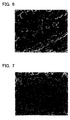
Fig. 7 shows an SEM image of a carbon film surface formed by the comparative examples. -
Fig. 8 shows an SEM image of a portion ofFig. 7 taken at larger scale. -
Fig. 9 shows a mold of a die casting device used in the embodiments and comparative examples. - In the surface treatment method of the present invention, preferably, a casting mold whose surface has already been covered by a nanocarbon film may be obtained, and fullerenes may be further applied to this casting mold. Further, the surface treatment method may preferably include a step of forming a carbon film containing nanocarbons on the casting mold, and a step of applying fullerenes to the surface of the carbon film that contains nanocarbons.
- A carbon film formed by the surface treatment method of the present invention includes fullerenes and at least one type of nanocarbon selected from the group of carbon nanocoils, carbon nanotubes and carbon nanofilaments. The carbon film formed by the surface treatment method of the present invention need not necessarily be composed only of carbon.
- Fullerenes are carbon clusters having a closed shell structure, and normally have an even number of carbon atoms ranging from 60∼130. Specific examples are: C60, C70, C76, C78, C80, C82, C84, C86, C88, C90; C92, C94, C96 and higher-order carbon clusters having a greater number of carbon atoms. Apart from the above fullerenes, the fullerenes in the present invention include fullerene derivatives in which other molecules or functional groups have been chemically modified in the fullerene molecules. In the fullerene applying step, the fullerene application may be performed using a mixture of the fullerenes and other substances.
- Preferred aspects of below embodiments will be listed.
- 1. In the fullerene applying step, a fullerene powder may be applied directly to the nanocarbon film.
- 2. In the nanocarbon film forming step, the nanocarbon film is formed, and a nitride film and a sulfurized film may be formed between the nanocarbon film and a treated base material.
- (Release Resistance Measurement Test)
A carbon film was formed on a steel surface according toEmbodiment 1 and Comparative Examples 1∼3, and the release resistance of a treated surface was measured using an automatic tension testing device Lub-Tester-U (MEC International). The Lub-Tester-U is a device in which, after aring body 2 is positioned on atest bed 1 and molten aluminum is poured into thering body 2, as shown inFig. 2 , aweight 3 is positioned after the aluminum has solidified, as shown inFig. 3 , and frictional resistance while pulling thering body 2 is measured by the device. Thetest bed 1 is manufactured from SKD61 (alloy tool steel: JIS G4404), and has the dimensions 200mm x 200mm x 30mm. The surface treatment described below was performed on thistest bed 1. - A nanocarbon film was formed on a surface of the
test bed 1 by the following method. Moreover, the following method was taught in Japanese Patent Application Publication No.2008-105082 - Nanocarbon Film Forming Process:
Thetest bed 1 was placed in an atmospheric furnace, air was purged using a vacuum pump, then nitrogen gas (N2) was circulated to create an N2 atmosphere. Next, in accordance with the process profile shown inFig. 4 , heating to 480°C for 0.5h was performed while reaction gas (hydrogen sulfide (H2S) gas, acetylene (C2H2) gas, ammonia (NH3) gas) was circulated. After 0.5h from beginning the heating, when 480°C was reached, supply of hydrogen sulfide gas was halted, then after a further 0.5h, supply of acetylene gas was halted. The temperature was maintained at 480°C for 4.5h while the ammonia gas was circulated, then supply of the ammonia gas was halted, the supply of gas was switched to nitrogen gas, and cooling was started. A nanocarbon film was thus formed on the surface of thetest bed 1, and a nitride film and sulfurized film were formed between the base material of thetest bed 1 and the nanocarbon film. - In
Embodiment 1, a fullerene applying process described below was further performed on thetest bed 1 which had undergone the nanocarbon film forming process. Moreover, inEmbodiment 1, fullerenes are applied to the surface of the nanocarbon film. - Fullerene Applying Process:
After thetest bed 1 was heated once to 300°C, fullerene C60 powder was applied to the nanocarbon film formed on the surface of thetest bed 1 using a cloth to which the fullerene C60 powder (nanom purple ST, manufactured by Frontier Carbon Corp.) had been applied. Sufficient fullerene powder was applied to the cloth, then the fullerene powder was applied to the entire nanocarbon film surface while pressing with an average pressure of 10∼300g/cm2. Moreover, while the fullerene powder was being applied using the cloth, the temperature of thetest bed 1 was between 100°C and less than 300°C. Using this method, the quantity of fullerenes applied to the surface of the test bed was 1mg/cm2. - (Comparative Example 1)
Only the fullerene applying process described inEmbodiment 1 was performed on thetest bed 1 having the same material, shape, and size asEmbodiment 1. - (Comparative Example 2)
Only the nanocarbon film forming process described inEmbodiment 1 was performed on thetest bed 1 having the same material, shape, and size asEmbodiment 1, and the fullerene applying process was not performed. - (Comparative Example 3)
Surface treatment was performed on thetest bed 1 having the same material, shape, and size asEmbodiment 1, with the order of the nanocarbon film forming process and the fullerene applying process described inEmbodiment 1 having been reversed. That is, first the fullerene applying process described inEmbodiment 1 was performed on thetest bed 1, forming the fullerene carbon film. Next, the nanocarbon film forming process described inEmbodiment 1 was performed on thetest bed 1 upon which the fullerene carbon film had been formed, forming the nanocarbon film on the surface of the fullerene carbon film. - Release Resistance Measurement Test:
The release resistance of thetest bed 1, which had undergone surface treatment according toEmbodiment 1 and Comparative Examples 1∼3, was measured using an automatic tension testing device. Thering body 2 was manufactured from SKD61, had a height of 50mm, and had an inner diameter 70mm and an outer diameter 90mm at the surface making contact with thetest bed 1. The inner diameter of thering body 2 increased slightly as it rose from the surface making contact with thetest bed 1. ADC12 (aluminum alloy die casting JIS H5302) was used in the molten aluminum. As shown inFig. 1 , a conventionally used silicon emulsion die lubricant was applied to the carbon film formed on thetest bed 1 and, as shown inFig. 2 , thering body 2 was mounted, 90cc of molten aluminum (ADC12) at 650°C was poured into thering body 2, was cooled for 40 seconds, and allowed to solidify. Further, as shown inFig. 3 , a9kg iron weight 3 was mounted, and the releasing load was measured while pulling thering body 2 at a constant speed of 50mm/s using a push-pull 4. The release resistance measurement test was repeated using the test beds which had undergone the surface treatment ofEmbodiment 1 and Comparative Examples 1∼3, and the changes in the releasing load were examined. The results are shown inFig. 5 . - In
Fig. 5 , the releasing load is on the vertical axis, and the number of implementations of the release resistance measurement test is shown on the horizontal axis as the number of moldings. In the test beds which had undergone the surface treatment of Comparative Examples 1∼3, an almost constant releasing load of 5∼8kgf could be maintained for a certain number of moldings. However, the releasing load increased markedly when a certain number of moldings was reached, rapidly exceeding 20kgf. By contrast, in the test bed which had undergone the surface treatment ofEmbodiment 1, a marked increase in releasing load, as in Comparative Examples 1∼3, did not occur even when the number of moldings exceeded 50, and a low releasing load of 5∼8kgf was maintained. - The greater the number of moldings until a marked increase in the releasing load, the longer the releasing effect can be said to last. From the results shown in
Fig. 5 , it was found that the carbon film formed by the surface treatment method as inEmbodiment 1 in which the nanocarbon film forming process is performed first and then the fullerene applying process is performed, has a longer release effectiveness than that formed by the surface treatment method as in Comparative Examples 1∼3, in which only one of the processes is performed, and has a longer release effectiveness than that formed by the surface treatment method in which the order of the two processes is reversed. - Further, in Comparative Example 1 and
Embodiment 1, the releasing load was nearly identical while the number of moldings was small (up to five), and was slightly less than in Comparative Example 2 and Comparative Example 3. It was conjectured that, since the outermost layer was covered by fullerenes in Comparative Example 1 andEmbodiment 1, release resistance was reduced by the fullerenes. Further, in Comparative Example 2, although the releasing load was slightly greater than in Comparative Example 1 for a small number of moldings, the number of moldings until the releasing load increased markedly was more than twice that of Comparative Example 1. This was conjectured to be due to the nanocarbon film formed in Comparative Example 2 peeling off less readily than the carbon film, to which the fullerenes had been applied, of Comparative Example 1. -
Fig. 6 is an SEM image of thetest bed 1 having the carbon film formed according toEmbodiment 1, andFigs. 7 ,8 are SEM images of thetest bed 1 having the carbon film formed according to Comparative Example 2. All were taken before performing the release resistance measurement test.Fig. 8 is an enlarged photograph of a portion ofFig. 7 , and the line in the lower right area of the photograph shows a length of 2µm. This shows that performing the nanocarbon film forming process according to Comparative Example 2 forms a nanocarbon film containing fiber-shaped nanocarbons on thetest bed 1.Fig. 6 is equivalent to an example in which the fullerene applying process has been further performed on the nanocarbon film ofFig. 7 . ComparingFig. 6 and Fig. 7 , surface unevenness has been reduced in the carbon film ofEmbodiment 1 shown inFig. 6 . That is, this shows that application of fullerenes to the surface of the nanocarbon film fills in the unevenness of the nanocarbon film and smoothens the carbon film surface. - Considering the results of the release resistance measurement test of
Fig. 5 together with the results of the SEM images ofFigs. 6, 7 , and8 , it was conjectured that, inEmbodiment 1, a lower releasing load was maintained for a greater number of moldings due to surface unevenness being mitigated by filling fullerenes into spaces in the nanocarbon film formed on the test bed surface, and by the fullerenes, which are highly effective in reducing release resistance, being trapped by the nanocarbon film which does not readily peel off the test bed surface. - (Sticking Test) In
Embodiment 2 and Comparative Example 4, surface treatment was performed on a molding surface of a die casting mold for casting aluminum products, as shown inFig. 9 , and the occurrence of sticking during the die casting process for aluminum products was tested. The die casting mold was a mold manufactured from SKD61 for a housing of a transaxle of a motor vehicle, and ADC12 was used in the aluminum alloy that was cast. As shown inFig. 9 , the die casting mold used in the sticking test consisted of a fixedmold 11 and amovable mold 12. When the fixedmold 11 and themovable mold 12 have been clamped together, a space available between the fixedmold 11 and themovable mold 12 is acavity 13, thiscavity 13 being surrounded by acavity surface 21 of the fixedmold 11 and acavity surface 22 of themovable mold 12. A moltenmetal pouring path 14,plunger 15, and moltenmetal input hole 16 are formed in the fixedmold 11. Aplate 18 and acast removal pin 17 for removing the product after casting are formed in themovable mold 12. The surface treatment ofEmbodiment 2 and Comparative Example 4, described below, was performed on the cavity surfaces 21, 22 of themovable mold 11 and the fixedmold 12. - As in
Embodiment 1, the nanocarbon film forming process and then the fullerene applying process were performed on the cavity surfaces 21, 22 of the fixedmold 11 and themovable mold 12, these constituting the die casting mold manufactured from SKD61 for casting a housing of a transaxle of a motor vehicle. - (Comparative Example 4)
Only the nanocarbon film forming process described inEmbodiment 1 was performed on the cavity surfaces 21, 22 of the fixedmold 11 andmovable mold 12 having the same material, shape, and size asEmbodiment 2, and the fullerene applying process was not performed. - Sticking Test:
The die casting mold for a housing of a transaxle of a motor vehicle, which underwent the surface treatment inEmbodiment 2 and Comparative Example 4, was repeatedly used for die casting aluminum products, and then was examined to see whether molten aluminum had stuck to the die casting mold. - A conventional silicon emulsion die lubricant was applied to the cavity surfaces 21, 22 of the fixed
mold 11 and themovable mold 12, then the fixedmold 11 andmovable mold 12 were clamped with a clamping pressure of 2000t. In the state ofFig. 9 , the casting was performed by pouring molten aluminum (ADC12) into the moltenmetal pouring path 14 from the moltenmetal input hole 16, and using theplunger 15 to inject the molten aluminum at 670°C into thecavity 13 with a casting pressure 46MPa and injection speed 3m/s. After the fixedmold 11 and themovable mold 12 were opened, the cast removal pin 17 (manufactured from SKD61) was moved in a direction of protruding from thecavity surface 22, and the cast aluminum product was removed. The procedures from applying the die lubricant to removing the molded product were treated as one sticking test shot, which was repeated. - After the sticking test was repeated, of the total surface area of the
cavity surface 21 of the fixedmold 11 and thecavity surface 22 of themovable mold 12, the portion of surface area where molten aluminum stuck was examined, and is shown in Table 1. The sticking area in Table 1 shows a ratio calculated using, as 1, the surface area where sticking occurred in Comparative Example 4. -
[Table 1] number of shots sticking surface area Embodiment 2 100 0.2 Comparative Example 4 50 1 - As shown in Table 1, in using the die casting mold which underwent surface treatment in
Embodiment 2, the sticking surface area was 0.2 that of the Comparative Example despite twice the number of shots than Comparative Example 4. That is, when using the casting mold having the carbon film created by the surface treatment method of the present invention, sticking of molten aluminum onto the casting mold during the aluminum casting could be significantly reduced. - As described above, when the casting mold surface treatment method of the present invention was performed, the effectiveness of reducing release resistance was maintained for longer, and the sticking of molten metal was inhibited. This was conjectured to be due to smoothening the unevenness of the surface by filling the fullerenes into the spaces in the nanocarbons film, and the fullerenes being trapped by the nanocarbon film, Smoothening was achieved by applying the fullerenes, which highly effectively reduce the release resistance, to the casting mold surface; this having been covered by the nanocarbon film which does not peel off readily. By lengthening the release effectiveness, the maintenance to restore the casting mold release effectiveness can be reduced, and the production efficiency in the casting process using the casting mold can be increased.
- Moreover, the method of forming the nanocarbon film of the present invention is not restricted to the method using an atmospheric furnace, as in the above embodiments. Further, the method of applying the fullerenes is not restricted to the method of applying fullerene powder directly to the nanocarbon film, as in the above embodiments.
- Specific examples of the present invention are described above in detail, but these examples are merely illustrative and place no limitation on the scope of the patent claims. The technology described in the patent claims also encompasses various changes and modifications to the specific examples described above.
- The technical elements explained in the present specification or drawings provide technical utility either independently or through various combinations. The present invention is not limited to the combinations described at the time the claims are filed Further; the purpose of the examples illustrated by the present specification or drawings is to satisfy multiple objectives simultaneously, and satisfying any one of those objectives gives technical utility to the present invention.
Claims (3)
- A casting mold surface treatment method comprising applying fullerenes to a surface of a carbon film, which covers a surface of a casting mold and contains at least one type of nanocarbon selected from the group of carbon nanocoils, carbon nanotubes and carbon nanofilaments.
- A casting mold surface treatment method comprising:a nanocarbon film forming step of forming, on a surface of a casting mold, a carbon film containing at least one type of nanocarbon selected from the group of carbon nanocoils, carbon nanotubes and carbon nanofilaments, anda fullerene applying step of applying fullerenes to a surface of the carbon film.
- A casting mold having its surface covered by a carbon film containing at least one type of nanocarbon selected from the group of carbon nanocoils, carbon nanotubes and carbon nanofilaments, wherein
fullerenes are included in the carbon film, and the fullerene content at a surface side of the carbon film is greater than the fullerene content at a casting mold side.
Applications Claiming Priority (2)
| Application Number | Priority Date | Filing Date | Title |
|---|---|---|---|
| JP2008198588A JP5036656B2 (en) | 2008-07-31 | 2008-07-31 | Surface treatment method for casting mold and casting mold using the same |
| PCT/JP2009/063559 WO2010013770A1 (en) | 2008-07-31 | 2009-07-30 | Method for treating surface of casting mold and casting mold using same |
Publications (3)
| Publication Number | Publication Date |
|---|---|
| EP2314399A1 true EP2314399A1 (en) | 2011-04-27 |
| EP2314399A4 EP2314399A4 (en) | 2012-05-02 |
| EP2314399B1 EP2314399B1 (en) | 2014-10-15 |
Family
ID=41610469
Family Applications (1)
| Application Number | Title | Priority Date | Filing Date |
|---|---|---|---|
| EP09803012.5A Active EP2314399B1 (en) | 2008-07-31 | 2009-07-30 | Method for treating surface of casting mold and casting mold using same |
Country Status (7)
| Country | Link |
|---|---|
| US (2) | US8256493B2 (en) |
| EP (1) | EP2314399B1 (en) |
| JP (1) | JP5036656B2 (en) |
| KR (1) | KR101193429B1 (en) |
| CN (1) | CN102105243B (en) |
| CA (1) | CA2730893C (en) |
| WO (1) | WO2010013770A1 (en) |
Cited By (3)
| Publication number | Priority date | Publication date | Assignee | Title |
|---|---|---|---|---|
| WO2012146977A1 (en) * | 2011-04-28 | 2012-11-01 | Toyota Jidosha Kabushiki Kaisha | Surface treatment method for metal material and mold treated by surface treatment method |
| WO2014024021A3 (en) * | 2012-08-10 | 2014-05-30 | Toyota Jidosha Kabushiki Kaisha | Casting mold and cast article produced using the same |
| EP2762250A4 (en) * | 2011-09-28 | 2015-05-20 | Toyota Motor Co Ltd | Member for casting, casting method, and method for producing lubricant used therefor |
Families Citing this family (16)
| Publication number | Priority date | Publication date | Assignee | Title |
|---|---|---|---|---|
| JP5036656B2 (en) * | 2008-07-31 | 2012-09-26 | トヨタ自動車株式会社 | Surface treatment method for casting mold and casting mold using the same |
| JP5060458B2 (en) | 2008-12-05 | 2012-10-31 | トヨタ自動車株式会社 | Die-cast mold and die-cast method |
| JP4554704B2 (en) * | 2008-12-10 | 2010-09-29 | トヨタ自動車株式会社 | Surface treatment method |
| JP5028502B2 (en) * | 2010-01-22 | 2012-09-19 | 株式会社豊田中央研究所 | Mold, solidified body and production method thereof |
| JP5614292B2 (en) * | 2011-01-11 | 2014-10-29 | トヨタ自動車株式会社 | Mold surface treatment method |
| JP5644590B2 (en) * | 2011-03-02 | 2014-12-24 | トヨタ自動車株式会社 | Surface treatment method |
| KR101257403B1 (en) | 2011-03-03 | 2013-04-23 | 동의대학교 산학협력단 | Electroforming Method Using Carbon Nano Tube Coating Film |
| JP5584658B2 (en) * | 2011-07-11 | 2014-09-03 | トヨタ自動車株式会社 | Maintenance method of molten metal detection sensor |
| CN102268634B (en) * | 2011-08-05 | 2012-10-17 | 肇庆理士电源技术有限公司 | Casting welding die and oxidation passivation method thereof |
| WO2013038503A1 (en) * | 2011-09-13 | 2013-03-21 | トヨタ自動車株式会社 | Film and method for manufacturing same |
| WO2013065197A1 (en) * | 2011-11-04 | 2013-05-10 | トヨタ自動車株式会社 | Porous body and method for producing same |
| JP5776790B2 (en) * | 2011-12-07 | 2015-09-09 | トヨタ自動車株式会社 | Casting member and manufacturing method thereof |
| JP5835129B2 (en) * | 2012-06-29 | 2015-12-24 | トヨタ自動車株式会社 | Surface treatment method |
| CN104338919B (en) * | 2013-07-25 | 2016-11-23 | 本田技研工业株式会社 | Casting molds |
| JP6197579B2 (en) * | 2013-10-29 | 2017-09-20 | トヨタ自動車株式会社 | Metal surface treatment method |
| JP2019038018A (en) * | 2017-08-25 | 2019-03-14 | アイシン精機株式会社 | Component for aluminum die-casting die |
Citations (2)
| Publication number | Priority date | Publication date | Assignee | Title |
|---|---|---|---|---|
| JP2007144499A (en) * | 2005-11-30 | 2007-06-14 | Toyota Motor Corp | Casting method and method for manufacturing casting mold |
| JP2008105082A (en) * | 2006-10-27 | 2008-05-08 | Matsuoka Tekkosho:Kk | Mold |
Family Cites Families (11)
| Publication number | Priority date | Publication date | Assignee | Title |
|---|---|---|---|---|
| JP4701568B2 (en) | 2001-09-14 | 2011-06-15 | 住友電気工業株式会社 | Covering member for metal forming machine |
| JP4680712B2 (en) * | 2004-08-16 | 2011-05-11 | トヨタ自動車株式会社 | Product forming method and film forming material member |
| CN102173410A (en) * | 2004-08-16 | 2011-09-07 | 株式会社Mec国际 | Article for film formation, method for film formation, and release agent |
| WO2006123748A1 (en) * | 2005-05-18 | 2006-11-23 | Mitsubishi Chemical Corporation | Carburized metal material and method for producing same |
| JP4832918B2 (en) | 2005-05-18 | 2011-12-07 | トヨタ自動車株式会社 | Carburized metal material and method for producing the same |
| JP4723908B2 (en) | 2005-05-27 | 2011-07-13 | トヨタ自動車株式会社 | Method for producing fullerene-containing extruded product |
| JP4799291B2 (en) | 2005-09-29 | 2011-10-26 | トヨタ自動車株式会社 | Alloy steel and manufacturing method thereof |
| JP4963362B2 (en) | 2005-10-28 | 2012-06-27 | トヨタ自動車株式会社 | Carbon film and method for producing the same |
| JP4895633B2 (en) | 2006-02-15 | 2012-03-14 | クレトイシ株式会社 | Rotating body for rotary film forming apparatus and method for producing the same |
| EP2154690A4 (en) * | 2007-04-27 | 2015-04-01 | Kuraray Co | Transparent conductive film and method for producing transparent conductive film |
| JP5036656B2 (en) * | 2008-07-31 | 2012-09-26 | トヨタ自動車株式会社 | Surface treatment method for casting mold and casting mold using the same |
-
2008
- 2008-07-31 JP JP2008198588A patent/JP5036656B2/en active Active
-
2009
- 2009-07-30 CN CN200980129008.5A patent/CN102105243B/en active Active
- 2009-07-30 EP EP09803012.5A patent/EP2314399B1/en active Active
- 2009-07-30 CA CA2730893A patent/CA2730893C/en active Active
- 2009-07-30 WO PCT/JP2009/063559 patent/WO2010013770A1/en active Application Filing
- 2009-07-30 KR KR1020117000903A patent/KR101193429B1/en active IP Right Grant
- 2009-07-30 US US13/056,520 patent/US8256493B2/en active Active
-
2012
- 2012-07-19 US US13/553,136 patent/US8413708B2/en active Active
Patent Citations (2)
| Publication number | Priority date | Publication date | Assignee | Title |
|---|---|---|---|---|
| JP2007144499A (en) * | 2005-11-30 | 2007-06-14 | Toyota Motor Corp | Casting method and method for manufacturing casting mold |
| JP2008105082A (en) * | 2006-10-27 | 2008-05-08 | Matsuoka Tekkosho:Kk | Mold |
Non-Patent Citations (1)
| Title |
|---|
| See also references of WO2010013770A1 * |
Cited By (6)
| Publication number | Priority date | Publication date | Assignee | Title |
|---|---|---|---|---|
| WO2012146977A1 (en) * | 2011-04-28 | 2012-11-01 | Toyota Jidosha Kabushiki Kaisha | Surface treatment method for metal material and mold treated by surface treatment method |
| KR101552415B1 (en) | 2011-04-28 | 2015-09-10 | 도요타지도샤가부시키가이샤 | Surface treatment method for metal material and mold treated by surface treatment method |
| US9644255B2 (en) | 2011-04-28 | 2017-05-09 | Toyota Jidosha Kabushiki Kaisha | Surface treatment method for metal material and mold treated by surface treatment method |
| EP2762250A4 (en) * | 2011-09-28 | 2015-05-20 | Toyota Motor Co Ltd | Member for casting, casting method, and method for producing lubricant used therefor |
| WO2014024021A3 (en) * | 2012-08-10 | 2014-05-30 | Toyota Jidosha Kabushiki Kaisha | Casting mold and cast article produced using the same |
| US9498818B2 (en) | 2012-08-10 | 2016-11-22 | Toyota Jidosha Kabushiki Kaisha | Casting mold and cast article produced using the same |
Also Published As
| Publication number | Publication date |
|---|---|
| JP5036656B2 (en) | 2012-09-26 |
| US8413708B2 (en) | 2013-04-09 |
| KR101193429B1 (en) | 2012-10-24 |
| WO2010013770A1 (en) | 2010-02-04 |
| CA2730893C (en) | 2012-07-03 |
| EP2314399B1 (en) | 2014-10-15 |
| CN102105243A (en) | 2011-06-22 |
| CA2730893A1 (en) | 2010-02-04 |
| JP2010036194A (en) | 2010-02-18 |
| US8256493B2 (en) | 2012-09-04 |
| EP2314399A4 (en) | 2012-05-02 |
| CN102105243B (en) | 2014-10-22 |
| KR20110018944A (en) | 2011-02-24 |
| US20110133053A1 (en) | 2011-06-09 |
| US20120288622A1 (en) | 2012-11-15 |
Similar Documents
| Publication | Publication Date | Title |
|---|---|---|
| EP2314399B1 (en) | Method for treating surface of casting mold and casting mold using same | |
| JP5008944B2 (en) | Mold | |
| JP4694358B2 (en) | Casting method and casting mold manufacturing method | |
| JP4868052B2 (en) | Mold surface treatment method | |
| EP2882549B1 (en) | Casting mold and cast article produced using the same | |
| DE112011101613T5 (en) | Process for the surface treatment of a casting mold | |
| WO2020018477A1 (en) | Aluminum casting alloys | |
| US8342230B2 (en) | Casting method | |
| HU208270B (en) | Lose-pattern, pressure precision casting method | |
| JP5618476B2 (en) | Die casting equipment | |
| EP2762250A1 (en) | Member for casting, casting method, and method for producing lubricant used therefor | |
| KR100537493B1 (en) | Die casting apparatus and die casting method | |
| JP3603658B2 (en) | Manufacturing method of forged member | |
| US20020003033A1 (en) | Method of casting and casting machine | |
| US6923242B2 (en) | Aluminum casting method | |
| EP1348504B1 (en) | Billet, horizontal continuous casting process, and thixocasting process | |
| JPS60108156A (en) | Production of composite member | |
| JP4121336B2 (en) | Manufacturing method of casting mold and layered steel member | |
| WO2019222138A1 (en) | Direct chill permanent mold casting system and method of same | |
| WO2004020685A1 (en) | Member made of steel product having layers formed thereon and method for producing member | |
| JP2014009394A (en) | Surface treatment method |
Legal Events
| Date | Code | Title | Description |
|---|---|---|---|
| PUAI | Public reference made under article 153(3) epc to a published international application that has entered the european phase |
Free format text: ORIGINAL CODE: 0009012 |
|
| 17P | Request for examination filed |
Effective date: 20110124 |
|
| AK | Designated contracting states |
Kind code of ref document: A1 Designated state(s): AT BE BG CH CY CZ DE DK EE ES FI FR GB GR HR HU IE IS IT LI LT LU LV MC MK MT NL NO PL PT RO SE SI SK SM TR |
|
| AX | Request for extension of the european patent |
Extension state: AL BA RS |
|
| DAX | Request for extension of the european patent (deleted) | ||
| A4 | Supplementary search report drawn up and despatched |
Effective date: 20120404 |
|
| RIC1 | Information provided on ipc code assigned before grant |
Ipc: B22C 9/06 20060101AFI20120329BHEP Ipc: B22D 17/20 20060101ALI20120329BHEP Ipc: B22C 3/00 20060101ALI20120329BHEP Ipc: C01B 31/02 20060101ALI20120329BHEP |
|
| RAP1 | Party data changed (applicant data changed or rights of an application transferred) |
Owner name: MEC INTERNATIONAL CO., LTD. Owner name: TOYOTA JIDOSHA KABUSHIKI KAISHA |
|
| 17Q | First examination report despatched |
Effective date: 20130702 |
|
| GRAP | Despatch of communication of intention to grant a patent |
Free format text: ORIGINAL CODE: EPIDOSNIGR1 |
|
| INTG | Intention to grant announced |
Effective date: 20140520 |
|
| GRAS | Grant fee paid |
Free format text: ORIGINAL CODE: EPIDOSNIGR3 |
|
| GRAA | (expected) grant |
Free format text: ORIGINAL CODE: 0009210 |
|
| AK | Designated contracting states |
Kind code of ref document: B1 Designated state(s): AT BE BG CH CY CZ DE DK EE ES FI FR GB GR HR HU IE IS IT LI LT LU LV MC MK MT NL NO PL PT RO SE SI SK SM TR |
|
| REG | Reference to a national code |
Ref country code: GB Ref legal event code: FG4D Ref country code: CH Ref legal event code: EP |
|
| REG | Reference to a national code |
Ref country code: IE Ref legal event code: FG4D |
|
| REG | Reference to a national code |
Ref country code: AT Ref legal event code: REF Ref document number: 691396 Country of ref document: AT Kind code of ref document: T Effective date: 20141115 |
|
| REG | Reference to a national code |
Ref country code: DE Ref legal event code: R096 Ref document number: 602009027234 Country of ref document: DE Effective date: 20141127 |
|
| REG | Reference to a national code |
Ref country code: NL Ref legal event code: VDEP Effective date: 20141015 |
|
| REG | Reference to a national code |
Ref country code: AT Ref legal event code: MK05 Ref document number: 691396 Country of ref document: AT Kind code of ref document: T Effective date: 20141015 |
|
| REG | Reference to a national code |
Ref country code: LT Ref legal event code: MG4D |
|
| PG25 | Lapsed in a contracting state [announced via postgrant information from national office to epo] |
Ref country code: NL Free format text: LAPSE BECAUSE OF FAILURE TO SUBMIT A TRANSLATION OF THE DESCRIPTION OR TO PAY THE FEE WITHIN THE PRESCRIBED TIME-LIMIT Effective date: 20141015 |
|
| PG25 | Lapsed in a contracting state [announced via postgrant information from national office to epo] |
Ref country code: LT Free format text: LAPSE BECAUSE OF FAILURE TO SUBMIT A TRANSLATION OF THE DESCRIPTION OR TO PAY THE FEE WITHIN THE PRESCRIBED TIME-LIMIT Effective date: 20141015 Ref country code: PT Free format text: LAPSE BECAUSE OF FAILURE TO SUBMIT A TRANSLATION OF THE DESCRIPTION OR TO PAY THE FEE WITHIN THE PRESCRIBED TIME-LIMIT Effective date: 20150216 Ref country code: IS Free format text: LAPSE BECAUSE OF FAILURE TO SUBMIT A TRANSLATION OF THE DESCRIPTION OR TO PAY THE FEE WITHIN THE PRESCRIBED TIME-LIMIT Effective date: 20150215 Ref country code: FI Free format text: LAPSE BECAUSE OF FAILURE TO SUBMIT A TRANSLATION OF THE DESCRIPTION OR TO PAY THE FEE WITHIN THE PRESCRIBED TIME-LIMIT Effective date: 20141015 Ref country code: ES Free format text: LAPSE BECAUSE OF FAILURE TO SUBMIT A TRANSLATION OF THE DESCRIPTION OR TO PAY THE FEE WITHIN THE PRESCRIBED TIME-LIMIT Effective date: 20141015 Ref country code: NO Free format text: LAPSE BECAUSE OF FAILURE TO SUBMIT A TRANSLATION OF THE DESCRIPTION OR TO PAY THE FEE WITHIN THE PRESCRIBED TIME-LIMIT Effective date: 20150115 |
|
| PG25 | Lapsed in a contracting state [announced via postgrant information from national office to epo] |
Ref country code: LV Free format text: LAPSE BECAUSE OF FAILURE TO SUBMIT A TRANSLATION OF THE DESCRIPTION OR TO PAY THE FEE WITHIN THE PRESCRIBED TIME-LIMIT Effective date: 20141015 Ref country code: SE Free format text: LAPSE BECAUSE OF FAILURE TO SUBMIT A TRANSLATION OF THE DESCRIPTION OR TO PAY THE FEE WITHIN THE PRESCRIBED TIME-LIMIT Effective date: 20141015 Ref country code: AT Free format text: LAPSE BECAUSE OF FAILURE TO SUBMIT A TRANSLATION OF THE DESCRIPTION OR TO PAY THE FEE WITHIN THE PRESCRIBED TIME-LIMIT Effective date: 20141015 Ref country code: CY Free format text: LAPSE BECAUSE OF FAILURE TO SUBMIT A TRANSLATION OF THE DESCRIPTION OR TO PAY THE FEE WITHIN THE PRESCRIBED TIME-LIMIT Effective date: 20141015 Ref country code: GR Free format text: LAPSE BECAUSE OF FAILURE TO SUBMIT A TRANSLATION OF THE DESCRIPTION OR TO PAY THE FEE WITHIN THE PRESCRIBED TIME-LIMIT Effective date: 20150116 Ref country code: HR Free format text: LAPSE BECAUSE OF FAILURE TO SUBMIT A TRANSLATION OF THE DESCRIPTION OR TO PAY THE FEE WITHIN THE PRESCRIBED TIME-LIMIT Effective date: 20141015 Ref country code: PL Free format text: LAPSE BECAUSE OF FAILURE TO SUBMIT A TRANSLATION OF THE DESCRIPTION OR TO PAY THE FEE WITHIN THE PRESCRIBED TIME-LIMIT Effective date: 20141015 |
|
| REG | Reference to a national code |
Ref country code: DE Ref legal event code: R097 Ref document number: 602009027234 Country of ref document: DE |
|
| PG25 | Lapsed in a contracting state [announced via postgrant information from national office to epo] |
Ref country code: CZ Free format text: LAPSE BECAUSE OF FAILURE TO SUBMIT A TRANSLATION OF THE DESCRIPTION OR TO PAY THE FEE WITHIN THE PRESCRIBED TIME-LIMIT Effective date: 20141015 Ref country code: SK Free format text: LAPSE BECAUSE OF FAILURE TO SUBMIT A TRANSLATION OF THE DESCRIPTION OR TO PAY THE FEE WITHIN THE PRESCRIBED TIME-LIMIT Effective date: 20141015 Ref country code: EE Free format text: LAPSE BECAUSE OF FAILURE TO SUBMIT A TRANSLATION OF THE DESCRIPTION OR TO PAY THE FEE WITHIN THE PRESCRIBED TIME-LIMIT Effective date: 20141015 Ref country code: DK Free format text: LAPSE BECAUSE OF FAILURE TO SUBMIT A TRANSLATION OF THE DESCRIPTION OR TO PAY THE FEE WITHIN THE PRESCRIBED TIME-LIMIT Effective date: 20141015 Ref country code: RO Free format text: LAPSE BECAUSE OF FAILURE TO SUBMIT A TRANSLATION OF THE DESCRIPTION OR TO PAY THE FEE WITHIN THE PRESCRIBED TIME-LIMIT Effective date: 20141015 |
|
| PLBE | No opposition filed within time limit |
Free format text: ORIGINAL CODE: 0009261 |
|
| STAA | Information on the status of an ep patent application or granted ep patent |
Free format text: STATUS: NO OPPOSITION FILED WITHIN TIME LIMIT |
|
| PG25 | Lapsed in a contracting state [announced via postgrant information from national office to epo] |
Ref country code: IT Free format text: LAPSE BECAUSE OF FAILURE TO SUBMIT A TRANSLATION OF THE DESCRIPTION OR TO PAY THE FEE WITHIN THE PRESCRIBED TIME-LIMIT Effective date: 20141015 |
|
| 26N | No opposition filed |
Effective date: 20150716 |
|
| PG25 | Lapsed in a contracting state [announced via postgrant information from national office to epo] |
Ref country code: MC Free format text: LAPSE BECAUSE OF FAILURE TO SUBMIT A TRANSLATION OF THE DESCRIPTION OR TO PAY THE FEE WITHIN THE PRESCRIBED TIME-LIMIT Effective date: 20141015 Ref country code: SI Free format text: LAPSE BECAUSE OF FAILURE TO SUBMIT A TRANSLATION OF THE DESCRIPTION OR TO PAY THE FEE WITHIN THE PRESCRIBED TIME-LIMIT Effective date: 20141015 |
|
| REG | Reference to a national code |
Ref country code: CH Ref legal event code: PL |
|
| PG25 | Lapsed in a contracting state [announced via postgrant information from national office to epo] |
Ref country code: LU Free format text: LAPSE BECAUSE OF FAILURE TO SUBMIT A TRANSLATION OF THE DESCRIPTION OR TO PAY THE FEE WITHIN THE PRESCRIBED TIME-LIMIT Effective date: 20150730 |
|
| REG | Reference to a national code |
Ref country code: IE Ref legal event code: MM4A |
|
| PG25 | Lapsed in a contracting state [announced via postgrant information from national office to epo] |
Ref country code: CH Free format text: LAPSE BECAUSE OF NON-PAYMENT OF DUE FEES Effective date: 20150731 Ref country code: LI Free format text: LAPSE BECAUSE OF NON-PAYMENT OF DUE FEES Effective date: 20150731 |
|
| REG | Reference to a national code |
Ref country code: FR Ref legal event code: PLFP Year of fee payment: 8 |
|
| PG25 | Lapsed in a contracting state [announced via postgrant information from national office to epo] |
Ref country code: IE Free format text: LAPSE BECAUSE OF NON-PAYMENT OF DUE FEES Effective date: 20150730 |
|
| PG25 | Lapsed in a contracting state [announced via postgrant information from national office to epo] |
Ref country code: MT Free format text: LAPSE BECAUSE OF FAILURE TO SUBMIT A TRANSLATION OF THE DESCRIPTION OR TO PAY THE FEE WITHIN THE PRESCRIBED TIME-LIMIT Effective date: 20141015 |
|
| PG25 | Lapsed in a contracting state [announced via postgrant information from national office to epo] |
Ref country code: SM Free format text: LAPSE BECAUSE OF FAILURE TO SUBMIT A TRANSLATION OF THE DESCRIPTION OR TO PAY THE FEE WITHIN THE PRESCRIBED TIME-LIMIT Effective date: 20141015 Ref country code: BG Free format text: LAPSE BECAUSE OF FAILURE TO SUBMIT A TRANSLATION OF THE DESCRIPTION OR TO PAY THE FEE WITHIN THE PRESCRIBED TIME-LIMIT Effective date: 20141015 Ref country code: HU Free format text: LAPSE BECAUSE OF FAILURE TO SUBMIT A TRANSLATION OF THE DESCRIPTION OR TO PAY THE FEE WITHIN THE PRESCRIBED TIME-LIMIT; INVALID AB INITIO Effective date: 20090730 |
|
| REG | Reference to a national code |
Ref country code: FR Ref legal event code: PLFP Year of fee payment: 9 |
|
| PG25 | Lapsed in a contracting state [announced via postgrant information from national office to epo] |
Ref country code: TR Free format text: LAPSE BECAUSE OF FAILURE TO SUBMIT A TRANSLATION OF THE DESCRIPTION OR TO PAY THE FEE WITHIN THE PRESCRIBED TIME-LIMIT Effective date: 20141015 |
|
| PG25 | Lapsed in a contracting state [announced via postgrant information from national office to epo] |
Ref country code: BE Free format text: LAPSE BECAUSE OF FAILURE TO SUBMIT A TRANSLATION OF THE DESCRIPTION OR TO PAY THE FEE WITHIN THE PRESCRIBED TIME-LIMIT Effective date: 20141015 |
|
| REG | Reference to a national code |
Ref country code: FR Ref legal event code: PLFP Year of fee payment: 10 |
|
| PG25 | Lapsed in a contracting state [announced via postgrant information from national office to epo] |
Ref country code: MK Free format text: LAPSE BECAUSE OF FAILURE TO SUBMIT A TRANSLATION OF THE DESCRIPTION OR TO PAY THE FEE WITHIN THE PRESCRIBED TIME-LIMIT Effective date: 20141015 |
|
| P01 | Opt-out of the competence of the unified patent court (upc) registered |
Effective date: 20230427 |
|
| PGFP | Annual fee paid to national office [announced via postgrant information from national office to epo] |
Ref country code: FR Payment date: 20230608 Year of fee payment: 15 |
|
| PGFP | Annual fee paid to national office [announced via postgrant information from national office to epo] |
Ref country code: GB Payment date: 20230608 Year of fee payment: 15 |
|
| PGFP | Annual fee paid to national office [announced via postgrant information from national office to epo] |
Ref country code: DE Payment date: 20230607 Year of fee payment: 15 |