EP2313686B1 - A furnace system with internal flue gas recirculation - Google Patents
A furnace system with internal flue gas recirculation Download PDFInfo
- Publication number
- EP2313686B1 EP2313686B1 EP09764940.4A EP09764940A EP2313686B1 EP 2313686 B1 EP2313686 B1 EP 2313686B1 EP 09764940 A EP09764940 A EP 09764940A EP 2313686 B1 EP2313686 B1 EP 2313686B1
- Authority
- EP
- European Patent Office
- Prior art keywords
- furnace system
- interior area
- oxygen
- duct
- fluid
- Prior art date
- Legal status (The legal status is an assumption and is not a legal conclusion. Google has not performed a legal analysis and makes no representation as to the accuracy of the status listed.)
- Active
Links
Images

Classifications
-
- F—MECHANICAL ENGINEERING; LIGHTING; HEATING; WEAPONS; BLASTING
- F23—COMBUSTION APPARATUS; COMBUSTION PROCESSES
- F23C—METHODS OR APPARATUS FOR COMBUSTION USING FLUID FUEL OR SOLID FUEL SUSPENDED IN A CARRIER GAS OR AIR
- F23C5/00—Disposition of burners with respect to the combustion chamber or to one another; Mounting of burners in combustion apparatus
- F23C5/08—Disposition of burners
- F23C5/32—Disposition of burners to obtain rotating flames, i.e. flames moving helically or spirally
-
- F—MECHANICAL ENGINEERING; LIGHTING; HEATING; WEAPONS; BLASTING
- F23—COMBUSTION APPARATUS; COMBUSTION PROCESSES
- F23C—METHODS OR APPARATUS FOR COMBUSTION USING FLUID FUEL OR SOLID FUEL SUSPENDED IN A CARRIER GAS OR AIR
- F23C9/00—Combustion apparatus characterised by arrangements for returning combustion products or flue gases to the combustion chamber
-
- F—MECHANICAL ENGINEERING; LIGHTING; HEATING; WEAPONS; BLASTING
- F23—COMBUSTION APPARATUS; COMBUSTION PROCESSES
- F23C—METHODS OR APPARATUS FOR COMBUSTION USING FLUID FUEL OR SOLID FUEL SUSPENDED IN A CARRIER GAS OR AIR
- F23C9/00—Combustion apparatus characterised by arrangements for returning combustion products or flue gases to the combustion chamber
- F23C9/003—Combustion apparatus characterised by arrangements for returning combustion products or flue gases to the combustion chamber for pulverulent fuel
-
- F—MECHANICAL ENGINEERING; LIGHTING; HEATING; WEAPONS; BLASTING
- F23—COMBUSTION APPARATUS; COMBUSTION PROCESSES
- F23D—BURNERS
- F23D1/00—Burners for combustion of pulverulent fuel
- F23D1/02—Vortex burners, e.g. for cyclone-type combustion apparatus
-
- F—MECHANICAL ENGINEERING; LIGHTING; HEATING; WEAPONS; BLASTING
- F23—COMBUSTION APPARATUS; COMBUSTION PROCESSES
- F23L—SUPPLYING AIR OR NON-COMBUSTIBLE LIQUIDS OR GASES TO COMBUSTION APPARATUS IN GENERAL ; VALVES OR DAMPERS SPECIALLY ADAPTED FOR CONTROLLING AIR SUPPLY OR DRAUGHT IN COMBUSTION APPARATUS; INDUCING DRAUGHT IN COMBUSTION APPARATUS; TOPS FOR CHIMNEYS OR VENTILATING SHAFTS; TERMINALS FOR FLUES
- F23L7/00—Supplying non-combustible liquids or gases, other than air, to the fire, e.g. oxygen, steam
-
- F—MECHANICAL ENGINEERING; LIGHTING; HEATING; WEAPONS; BLASTING
- F23—COMBUSTION APPARATUS; COMBUSTION PROCESSES
- F23L—SUPPLYING AIR OR NON-COMBUSTIBLE LIQUIDS OR GASES TO COMBUSTION APPARATUS IN GENERAL ; VALVES OR DAMPERS SPECIALLY ADAPTED FOR CONTROLLING AIR SUPPLY OR DRAUGHT IN COMBUSTION APPARATUS; INDUCING DRAUGHT IN COMBUSTION APPARATUS; TOPS FOR CHIMNEYS OR VENTILATING SHAFTS; TERMINALS FOR FLUES
- F23L7/00—Supplying non-combustible liquids or gases, other than air, to the fire, e.g. oxygen, steam
- F23L7/007—Supplying oxygen or oxygen-enriched air
-
- F—MECHANICAL ENGINEERING; LIGHTING; HEATING; WEAPONS; BLASTING
- F23—COMBUSTION APPARATUS; COMBUSTION PROCESSES
- F23N—REGULATING OR CONTROLLING COMBUSTION
- F23N5/00—Systems for controlling combustion
- F23N5/003—Systems for controlling combustion using detectors sensitive to combustion gas properties
-
- F—MECHANICAL ENGINEERING; LIGHTING; HEATING; WEAPONS; BLASTING
- F23—COMBUSTION APPARATUS; COMBUSTION PROCESSES
- F23C—METHODS OR APPARATUS FOR COMBUSTION USING FLUID FUEL OR SOLID FUEL SUSPENDED IN A CARRIER GAS OR AIR
- F23C2202/00—Fluegas recirculation
- F23C2202/30—Premixing fluegas with combustion air
-
- F—MECHANICAL ENGINEERING; LIGHTING; HEATING; WEAPONS; BLASTING
- F23—COMBUSTION APPARATUS; COMBUSTION PROCESSES
- F23C—METHODS OR APPARATUS FOR COMBUSTION USING FLUID FUEL OR SOLID FUEL SUSPENDED IN A CARRIER GAS OR AIR
- F23C2202/00—Fluegas recirculation
- F23C2202/50—Control of recirculation rate
-
- F—MECHANICAL ENGINEERING; LIGHTING; HEATING; WEAPONS; BLASTING
- F23—COMBUSTION APPARATUS; COMBUSTION PROCESSES
- F23C—METHODS OR APPARATUS FOR COMBUSTION USING FLUID FUEL OR SOLID FUEL SUSPENDED IN A CARRIER GAS OR AIR
- F23C2900/00—Special features of, or arrangements for combustion apparatus using fluid fuels or solid fuels suspended in air; Combustion processes therefor
- F23C2900/09002—Specific devices inducing or forcing flue gas recirculation
-
- F—MECHANICAL ENGINEERING; LIGHTING; HEATING; WEAPONS; BLASTING
- F23—COMBUSTION APPARATUS; COMBUSTION PROCESSES
- F23L—SUPPLYING AIR OR NON-COMBUSTIBLE LIQUIDS OR GASES TO COMBUSTION APPARATUS IN GENERAL ; VALVES OR DAMPERS SPECIALLY ADAPTED FOR CONTROLLING AIR SUPPLY OR DRAUGHT IN COMBUSTION APPARATUS; INDUCING DRAUGHT IN COMBUSTION APPARATUS; TOPS FOR CHIMNEYS OR VENTILATING SHAFTS; TERMINALS FOR FLUES
- F23L2900/00—Special arrangements for supplying or treating air or oxidant for combustion; Injecting inert gas, water or steam into the combustion chamber
- F23L2900/07005—Injecting pure oxygen or oxygen enriched air
-
- F—MECHANICAL ENGINEERING; LIGHTING; HEATING; WEAPONS; BLASTING
- F23—COMBUSTION APPARATUS; COMBUSTION PROCESSES
- F23L—SUPPLYING AIR OR NON-COMBUSTIBLE LIQUIDS OR GASES TO COMBUSTION APPARATUS IN GENERAL ; VALVES OR DAMPERS SPECIALLY ADAPTED FOR CONTROLLING AIR SUPPLY OR DRAUGHT IN COMBUSTION APPARATUS; INDUCING DRAUGHT IN COMBUSTION APPARATUS; TOPS FOR CHIMNEYS OR VENTILATING SHAFTS; TERMINALS FOR FLUES
- F23L2900/00—Special arrangements for supplying or treating air or oxidant for combustion; Injecting inert gas, water or steam into the combustion chamber
- F23L2900/07009—Injection of steam into the combustion chamber
-
- Y—GENERAL TAGGING OF NEW TECHNOLOGICAL DEVELOPMENTS; GENERAL TAGGING OF CROSS-SECTIONAL TECHNOLOGIES SPANNING OVER SEVERAL SECTIONS OF THE IPC; TECHNICAL SUBJECTS COVERED BY FORMER USPC CROSS-REFERENCE ART COLLECTIONS [XRACs] AND DIGESTS
- Y02—TECHNOLOGIES OR APPLICATIONS FOR MITIGATION OR ADAPTATION AGAINST CLIMATE CHANGE
- Y02E—REDUCTION OF GREENHOUSE GAS [GHG] EMISSIONS, RELATED TO ENERGY GENERATION, TRANSMISSION OR DISTRIBUTION
- Y02E20/00—Combustion technologies with mitigation potential
- Y02E20/34—Indirect CO2mitigation, i.e. by acting on non CO2directly related matters of the process, e.g. pre-heating or heat recovery
Definitions
- the present invention relates generally to a fossil fuel fired furnace system, and more particularly, to an oxyfuel fired furnace system having an internal flue gas recirculation system.
- boilers can be used to produce steam for use in electric turbines and in chemical processes for providing energy to initiate a chemical reaction.
- the combustion process employed in boilers often utilizes fossil fuels such as coal or oil.
- pollutants such as unburned fuel, particulate, ash, NOx and other combustion byproducts are generated. If allowed to enter the atmosphere in sufficient amounts, these pollutants can detrimentally impact the environment and pose health hazards to humans and animals.
- a furnace system including a combustion vessel.
- a flue duct is coupled to an outlet end of the combustion vessel and is in fluid communication with an interior area defined thereby.
- a recirculation duct also forms a portion of the furnace system and extends outwardly from the flue duct and provides fluid communication between the flue duct and the interior area of the combustion vessel.
- a conveying device is disposed at least partially in the recirculation duct for facilitating flow of one or more fluids through the recirculation duct into the interior area of the combustion vessel in response to commands issued from a controller.
- the conveying device is an eductor for conveying a fluid such as, but not limited to oxygen, steam, flue gas or combinations thereof into the interior area defined by the combustion vessel.
- a furnace system generally designated by the reference number 10, includes a combustion vessel 12 defining an interior area 14.
- the combustion vessel 12 also defines a hopper 18 at a lower portion of an end 16 thereof.
- the combustion vessel 12 defines a conduit 19 which during operation, conveys flue gases FG out of the combustion vessel.
- the combustion vessel 12 also defines a first and a second aperture, 20 and 22 respectively, that open into the interior area 14.
- a manifold 24 or wind box is coupled to the combustion vessel 12 and is in fluid communication with the interior area 14.
- the manifold 24 has an inwardly facing opening 26 and two outwardly facing openings 28 and 30.
- the manifold 24 wraps around a portion of the combustion vessel 12. Portions of the manifold 24 are positioned over at least one of the first and second apertures, 20 and 22 respectively, such that an interior area 34 defined by the manifold is in fluid communication with the interior area 14 of the combustion vessel 12.
- the interior area 14 of the combustion vessel 12 is also in fluid communication with flue duct 42 for facilitating the flow of flue gas FG therethrough.
- flue duct 44 is in fluid communication with the flue duct 42 as well as with a second hopper section 46.
- a first heat exchanger for example an economizer 45, is positioned in and is in fluid communication with the flue duct 44. During operation, the economizer 45 cools the flue gas FG flowing therethrough.
- a second heat exchanger 50 such as an air preheater, is positioned downstream of and is in fluid communication with the flue duct 44 via, in the illustrated embodiment, conduit 48.
- a second conduit 52 extends between and is in fluid communication with the flue duct 44 and the manifold 24. The second conduit 52 extends from the flue duct 44 downstream of an outlet 47 of the economizer 45.
- economizer 45 is described as being one potential means of cooling the flue gas FG, other heat exchanger means may be employed, such as but not limited to ultra critical steam panels, steam heating means, steam production means and combinations thereof without departing from the broader aspects disclosed herein.
- the second conduit 52 and the manifold 24 cooperate to define a recirculation duct 55 which provides fluid communication between the flue duct 44 and the interior area 14 of the combustion vessel 12.
- the second conduit 52 can be installed during initial construction of the furnace system 10 or can be installed during a retrofit operation, after initial construction.
- the furnace system 10 also includes a pollution control system 54 in fluid communication with, and positioned downstream of, the second heat exchanger 50.
- the furnace system of FIG. 2 is similar to that illustrated in FIG. 1 , therefore like elements are assigned like numerals, preceded by the number 1.
- the furnace system generally designated by the reference number 110, includes a combustion vessel 112 defining an interior area 114.
- the combustion vessel 112 defines a first and a second aperture 120 and 122, respectively, that open into the interior area 114.
- a manifold 124 or wind box is coupled to the combustion vessel 112 and is in fluid communication with the interior area 114.
- the manifold 124 is positioned over at least one of the first and second apertures 120 and 122, respectively, such that an interior area 134 defined by the manifold is in fluid communication with the interior area 114 of the combustion vessel 112.
- the interior area 114 of the combustion vessel 112 is in fluid communication with flue duct 142 for facilitating the flow of flue gas FG therethrough.
- flue duct 144 is in fluid communication with the flue duct 142.
- a first heat exchanger, for example an economizer 145 is positioned in and is in fluid communication with the flue duct 144.
- a second conduit 152 extends between and is in fluid communication with flue duct 144 and the manifold 124. The second conduit 152 extends from the flue duct 144 downstream of an outlet 147 of the economizer 145.
- a second heat exchanger 150 such as an air preheater, is positioned downstream of and is in fluid communication with the flue duct 144 via, in the illustrated embodiment, conduit 148.
- the second conduit 152 and the manifold 124 cooperate to define a recirculation duct 155 which provides fluid communication between the flue duct 144 and the interior area 114 of the combustion vessel 112.
- the furnace system 110 further includes a pollution control system 154 in fluid communication with, and positioned downstream of, the second heat exchanger 150.
- an eductor 156 is positioned in the second conduit 152 for facilitating flow of one or more fluids into the interior area 114 of the combustion vessel 112 in response to commands, for example a command signal regarding combustion vessel temperature regulation, steam production and/or steam parameter measurement, issued from a controller 178 such as, but not limited, to a computer or programmable logic controller.
- a motive fluid, such as oxygen, is supplied to a portion 158, such as a central portion, of the eductor 156 at a predetermined pressure e.g. 34473,78 to 344737,86 N/m 2 ( 5 to 50 psig).
- An air stream designated by arrow A flows into an air separation unit 160 which separates nitrogen from the air and supplies oxygen to the eductor 156 via suitable piping 162.
- Flow of pressurized oxygen into the central portion 158 of the eductor causes flue gas FG to be entrained into an inlet 164 of the eductor and discharged through an outlet 166 of the eductor together with the oxygen into the interior area 134 of the manifold 124 and into the interior area 114 of the combustion vessel 112.
- air separation unit 160 is shown and described as supplying oxygen to the eductor 156, it is contemplated that other means of supplying the oxygen can be employed, including but not limited to an oxygen sources such as oxygen tanks and/or cylinders in addition to or in place of the air separation unit.
- Recirculation of a portion of the flue gas FG into the combustion vessel 112 helps regulate furnace temperatures and steam conditions within a predetermined range and allows a greater mass flow of gas through the combustion vessel.
- recirculation of the flue gas FG into the combustion vessel reduces the overall mass flow rate of flue gas flowing downstream of the flue duct 144.
- the introduction of oxygen (or any low nitrogen fluid) into the combustion vessel 112 reduces pollutants and the recirculation of flue gas FG into the combustion vessel 112 reduces the mass flow rate of the flue gas FG to be treated by the pollution control system 154, thus smaller, less costly second heat exchangers 150 and pollution control systems can be employed.
- oxygen is described as the motive fluid for use in the eductor 156
- other fluids can be employed including but not limited to steam, flue gas, flue gas processed by the pollution control system 154 or a combination thereof.
- the eductor 156 is shown and described as being positioned in the second conduit 152 for discharging oxygen and flue gas FG into the combustion vessel 112
- other devices for conveying the flue gas into the combustion vessel can be employed including but not limited to a compressor, fan or blower as illustrated in FIG. 3 as described below.
- eductor 156 is shown and described as being positioned in the second conduit 152, it is contemplated that portions of the eductor may extend outside of the second conduit, for example into the manifold 124, into the flue duct 144 and/or protrude into an external area 159 outside of the second conduit.
- the furnace system 210 includes a fan 270 disposed in the second conduit 252 for conveying flue gas FG from the flue duct 244 into the interior area 214 of the combustion vessel 212.
- the fan 270 is coupled to a drive unit (not shown) which operates the fan in response to a command signal, for example a command signal regarding combustion vessel temperature regulation, steam production and/or steam parameter measurement, issued by a controller 278 such as, but not limited to, a computer or programmable logic controller.
- a fan 270 is shown and described for conveying the flue gas FG from the duct 244 into the combustion vessel 212, other devices such as, but not limited to, blowers and compressors can be employed without departing from the broader aspects disclosed herein.
- the fan 270 is shown and described as being positioned in the second conduit 252, it is contemplated that portions of the fan and/or drive unit may extend outside of the second conduit, for example into the manifold 224, into the flue duct 144 and/or protrude into the external area 159 outside of the second conduit.
- a tangentially fired furnace 310 includes a combustion vessel 312 having an interior area 314.
- the combustion vessel 312 is illustrated with four apertures 320, 321, 322 and 323 extending therethrough.
- a lance 380, 381, 382 and 383 is positioned in respective ones of the apertures 320, 321, 322 and 323 and oriented at a predetermined angle T measured from respective adjacent portions of the combustion vessel 312.
- the angle T is of an appropriate magnitude, for example an acute angle, to cause a fluid, such as oxygen, and fuel flowing through the lance to rotate in the interior area 314 as shown by the arrows R.
- the lances 380, 381, 382 and 383 extend into the interior area 336 of the combustion chamber 312 for improved control of the combustion process. While the lances 380, 381, 382 and 383 are shown and described as being positioned in respective ones of the apertures 320, 321, 322 and 323 and oriented at a predetermined angle T measured from respective adjacent portions of the combustion vessel 312, it is contemplated that nozzles can be substituted for or positioned on a distal end of the lances.
- fuel F such as pulverized coal
- the fuel F can be blown into the manifold 24 along with a combustion fluid such as oxygen.
- flue gas FG exits the conduit end portion 119 of the combustion vessel 112 and flows through the flue ducts 142 and 144, respectively, to the second heat exchanger 150 and to the pollution control unit 154 for processing.
- a portion of the flue gas FG is re-circulated to the combustion vessel 112 through the second conduit 152 by operation of the eductor 156.
- the eductor 156 operates in response to a command signal, for example a command signal regarding combustion vessel temperature regulation, steam production and/or steam parameter measurement, generated from the controller 178. Operation of the eductor 156 causes pressurized oxygen to flow through the eductor and thereby entrain flue gas from the flue duct 144. The eductor 156 discharges the oxygen and the flue gas FG into the interior area 134 of the manifold 124 and into the interior area 114 of the combustion vessel 112. The oxygen is provided to the eductor 156 by the air separation unit 160.
- a command signal for example a command signal regarding combustion vessel temperature regulation, steam production and/or steam parameter measurement
Landscapes
- Engineering & Computer Science (AREA)
- Chemical & Material Sciences (AREA)
- Combustion & Propulsion (AREA)
- Mechanical Engineering (AREA)
- General Engineering & Computer Science (AREA)
- Air Supply (AREA)
- Waste-Gas Treatment And Other Accessory Devices For Furnaces (AREA)
- Chimneys And Flues (AREA)
- Combustion Of Fluid Fuel (AREA)
Description
- The present invention relates generally to a fossil fuel fired furnace system, and more particularly, to an oxyfuel fired furnace system having an internal flue gas recirculation system.
- Steam generators, also referred to as boilers or furnaces, are used in various systems. For example, boilers can be used to produce steam for use in electric turbines and in chemical processes for providing energy to initiate a chemical reaction. The combustion process employed in boilers often utilizes fossil fuels such as coal or oil. Generally, during the combustion process pollutants such as unburned fuel, particulate, ash, NOx and other combustion byproducts are generated. If allowed to enter the atmosphere in sufficient amounts, these pollutants can detrimentally impact the environment and pose health hazards to humans and animals.
- From
US 4, 294, 178 a furnace is known that bums pulverized coal. A part of the flue gas is recirculated back to the furnace to reduce the combustion temperature. - From
US 5, 309, 850 a closed combustion system is known that is used to incinerate hazardous wastes and vitrify ash. An incinerator is provided that is supplied with pure oxygen, hazardous waste and fuel for incinerating the hazardous waste. Using pure oxygen results in higher flame temperatures than those in air fired boilers. - According to aspects illustrated herein, there is provided a furnace system including a combustion vessel. A flue duct is coupled to an outlet end of the combustion vessel and is in fluid communication with an interior area defined thereby. A recirculation duct also forms a portion of the furnace system and extends outwardly from the flue duct and provides fluid communication between the flue duct and the interior area of the combustion vessel.
- According to the invention as defined in claim 1, a conveying device is disposed at least partially in the recirculation duct for facilitating flow of one or more fluids through the recirculation duct into the interior area of the combustion vessel in response to commands issued from a controller. The conveying device is an eductor for conveying a fluid such as, but not limited to oxygen, steam, flue gas or combinations thereof into the interior area defined by the combustion vessel.
- The above described and other features are illustrated by the following figures and detailed description.
- Referring now to the Figures, which are exemplary embodiments, and wherein like elements are numbered alike:
-
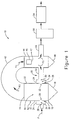
FIG. 1 schematically illustrates a furnace system in accordance with an embodiment which is not covered by the present invention; -
FIG. 2 schematically illustrates the furnace system ofFIG. 1 with an eductor type conveying device in accordance with the present invention; -
FIG. 3 schematically illustrates a portion of the furnace system ofFIG. 1 and shows a fan-type conveying device hazardous waste; and -
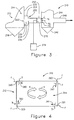
FIG. 4 is a cross sectional view of the furnace system ofFIG. 1 showing a tangential firing configuration. - As shown in
FIG. 1 , a furnace system, generally designated by thereference number 10, includes acombustion vessel 12 defining aninterior area 14. Thecombustion vessel 12 also defines ahopper 18 at a lower portion of anend 16 thereof. Generally opposite thehopper 18, thecombustion vessel 12 defines aconduit 19 which during operation, conveys flue gases FG out of the combustion vessel. In the illustrated embodiment, thecombustion vessel 12 also defines a first and a second aperture, 20 and 22 respectively, that open into theinterior area 14. - Still referring to
FIG. 1 , amanifold 24 or wind box is coupled to thecombustion vessel 12 and is in fluid communication with theinterior area 14. The manifold 24 has an inwardly facing opening 26 and two outwardly facingopenings manifold 24 wraps around a portion of thecombustion vessel 12. Portions of themanifold 24 are positioned over at least one of the first and second apertures, 20 and 22 respectively, such that aninterior area 34 defined by the manifold is in fluid communication with theinterior area 14 of thecombustion vessel 12. - The
interior area 14 of thecombustion vessel 12 is also in fluid communication withflue duct 42 for facilitating the flow of flue gas FG therethrough. Similarly,flue duct 44 is in fluid communication with theflue duct 42 as well as with asecond hopper section 46. A first heat exchanger, for example aneconomizer 45, is positioned in and is in fluid communication with theflue duct 44. During operation, theeconomizer 45 cools the flue gas FG flowing therethrough. Asecond heat exchanger 50, such as an air preheater, is positioned downstream of and is in fluid communication with theflue duct 44 via, in the illustrated embodiment,conduit 48. Asecond conduit 52 extends between and is in fluid communication with theflue duct 44 and themanifold 24. Thesecond conduit 52 extends from theflue duct 44 downstream of anoutlet 47 of theeconomizer 45. - While the
economizer 45 is described as being one potential means of cooling the flue gas FG, other heat exchanger means may be employed, such as but not limited to ultra critical steam panels, steam heating means, steam production means and combinations thereof without departing from the broader aspects disclosed herein. - The
second conduit 52 and themanifold 24 cooperate to define arecirculation duct 55 which provides fluid communication between theflue duct 44 and theinterior area 14 of thecombustion vessel 12. Thesecond conduit 52 can be installed during initial construction of thefurnace system 10 or can be installed during a retrofit operation, after initial construction. Thefurnace system 10 also includes apollution control system 54 in fluid communication with, and positioned downstream of, thesecond heat exchanger 50. - The furnace system of
FIG. 2 is similar to that illustrated inFIG. 1 , therefore like elements are assigned like numerals, preceded by the number 1. Accordingly the furnace system, generally designated by thereference number 110, includes acombustion vessel 112 defining aninterior area 114. Thecombustion vessel 112 defines a first and asecond aperture interior area 114. Amanifold 124 or wind box is coupled to thecombustion vessel 112 and is in fluid communication with theinterior area 114. Themanifold 124 is positioned over at least one of the first andsecond apertures interior area 134 defined by the manifold is in fluid communication with theinterior area 114 of thecombustion vessel 112. - The
interior area 114 of thecombustion vessel 112 is in fluid communication withflue duct 142 for facilitating the flow of flue gas FG therethrough. Similarly,flue duct 144 is in fluid communication with theflue duct 142. A first heat exchanger, for example aneconomizer 145 is positioned in and is in fluid communication with theflue duct 144. Asecond conduit 152 extends between and is in fluid communication withflue duct 144 and themanifold 124. Thesecond conduit 152 extends from theflue duct 144 downstream of anoutlet 147 of theeconomizer 145. Asecond heat exchanger 150, such as an air preheater, is positioned downstream of and is in fluid communication with theflue duct 144 via, in the illustrated embodiment, conduit 148. Thesecond conduit 152 and themanifold 124 cooperate to define arecirculation duct 155 which provides fluid communication between theflue duct 144 and theinterior area 114 of thecombustion vessel 112. Thefurnace system 110 further includes apollution control system 154 in fluid communication with, and positioned downstream of, thesecond heat exchanger 150. - Still referring to
FIG. 2 , aneductor 156 is positioned in thesecond conduit 152 for facilitating flow of one or more fluids into theinterior area 114 of thecombustion vessel 112 in response to commands, for example a command signal regarding combustion vessel temperature regulation, steam production and/or steam parameter measurement, issued from acontroller 178 such as, but not limited, to a computer or programmable logic controller. A motive fluid, such as oxygen, is supplied to aportion 158, such as a central portion, of theeductor 156 at a predetermined pressure e.g.34473,78 344737,86 air separation unit 160 which separates nitrogen from the air and supplies oxygen to theeductor 156 viasuitable piping 162. Flow of pressurized oxygen into thecentral portion 158 of the eductor, possibly by a nozzle, causes flue gas FG to be entrained into aninlet 164 of the eductor and discharged through anoutlet 166 of the eductor together with the oxygen into theinterior area 134 of themanifold 124 and into theinterior area 114 of thecombustion vessel 112. - While the
air separation unit 160 is shown and described as supplying oxygen to theeductor 156, it is contemplated that other means of supplying the oxygen can be employed, including but not limited to an oxygen sources such as oxygen tanks and/or cylinders in addition to or in place of the air separation unit. - Recirculation of a portion of the flue gas FG into the
combustion vessel 112 helps regulate furnace temperatures and steam conditions within a predetermined range and allows a greater mass flow of gas through the combustion vessel. In addition, recirculation of the flue gas FG into the combustion vessel reduces the overall mass flow rate of flue gas flowing downstream of theflue duct 144. The introduction of oxygen (or any low nitrogen fluid) into thecombustion vessel 112 reduces pollutants and the recirculation of flue gas FG into thecombustion vessel 112 reduces the mass flow rate of the flue gas FG to be treated by thepollution control system 154, thus smaller, less costlysecond heat exchangers 150 and pollution control systems can be employed. - Although, oxygen is described as the motive fluid for use in the
eductor 156, other fluids can be employed including but not limited to steam, flue gas, flue gas processed by thepollution control system 154 or a combination thereof. While theeductor 156 is shown and described as being positioned in thesecond conduit 152 for discharging oxygen and flue gas FG into thecombustion vessel 112, other devices for conveying the flue gas into the combustion vessel can be employed including but not limited to a compressor, fan or blower as illustrated inFIG. 3 as described below. Although theeductor 156 is shown and described as being positioned in thesecond conduit 152, it is contemplated that portions of the eductor may extend outside of the second conduit, for example into the manifold 124, into theflue duct 144 and/or protrude into anexternal area 159 outside of the second conduit. - The furnace system of
FIG. 3 is similar to that illustrated inFIG. 1 , therefore like elements are assigned like numerals, preceded by the number 2. As illustrated inFIG. 3 , thefurnace system 210 includes afan 270 disposed in thesecond conduit 252 for conveying flue gas FG from theflue duct 244 into theinterior area 214 of thecombustion vessel 212. Thefan 270 is coupled to a drive unit (not shown) which operates the fan in response to a command signal, for example a command signal regarding combustion vessel temperature regulation, steam production and/or steam parameter measurement, issued by acontroller 278 such as, but not limited to, a computer or programmable logic controller. - While a
fan 270 is shown and described for conveying the flue gas FG from theduct 244 into thecombustion vessel 212, other devices such as, but not limited to, blowers and compressors can be employed without departing from the broader aspects disclosed herein. Although thefan 270 is shown and described as being positioned in thesecond conduit 252, it is contemplated that portions of the fan and/or drive unit may extend outside of the second conduit, for example into the manifold 224, into theflue duct 144 and/or protrude into theexternal area 159 outside of the second conduit. - The furnace system of
FIG. 4 is similar to that illustrated inFIG. 1 , therefore like elements are assigned like numerals, preceded by the number 3. Referring toFIG 4 , a tangentially firedfurnace 310 includes acombustion vessel 312 having aninterior area 314. Thecombustion vessel 312 is illustrated with fourapertures lance apertures combustion vessel 312. The angle T is of an appropriate magnitude, for example an acute angle, to cause a fluid, such as oxygen, and fuel flowing through the lance to rotate in theinterior area 314 as shown by the arrows R. Thelances combustion chamber 312 for improved control of the combustion process. While thelances apertures combustion vessel 312, it is contemplated that nozzles can be substituted for or positioned on a distal end of the lances. - Referring back to
FIG. 2 , during operation, fuel F, such as pulverized coal, is conveyed into theinterior area 134 of the manifold 124 through theopening 128 and into theinterior area 114 of thecombustion vessel 112 for initiation of combustion. The fuel F can be blown into the manifold 24 along with a combustion fluid such as oxygen. As a result of the combustion, flue gas FG exits theconduit end portion 119 of thecombustion vessel 112 and flows through theflue ducts second heat exchanger 150 and to thepollution control unit 154 for processing. A portion of the flue gas FG is re-circulated to thecombustion vessel 112 through thesecond conduit 152 by operation of theeductor 156. Theeductor 156 operates in response to a command signal, for example a command signal regarding combustion vessel temperature regulation, steam production and/or steam parameter measurement, generated from thecontroller 178. Operation of the eductor 156 causes pressurized oxygen to flow through the eductor and thereby entrain flue gas from theflue duct 144. The eductor 156 discharges the oxygen and the flue gas FG into theinterior area 134 of the manifold 124 and into theinterior area 114 of thecombustion vessel 112. The oxygen is provided to theeductor 156 by theair separation unit 160. - While the invention has been described with reference to various exemplary embodiments, it will be understood by those skilled in the art that various changes may be made and equivalents may be substituted for elements thereof without departing from the scope of the invention. In addition, many modifications may be made to adapt a particular situation or material to the teachings of the invention without departing from the essential scope thereof. Therefore, it is intended that the invention not be limited to the particular embodiment disclosed as the best mode contemplated for carrying out this invention, but that the invention will include all embodiments falling within the scope of the appended claims.
Claims (13)
- A furnace system for combusting fuel and oxygen comprising:An oxy-fuel combustion vessel (112) that receives fuel and oxygen for combustion therein, having an outlet end (116) and at least one aperture (120, 122), that opens into an interior area (114) defined by said oxy-fuel combustion vessel (112);an oxygen source (160) to supply a gas stream of oxygen to the oxy-fuel combustion vessel (112);a flue duct (144) coupled to said outlet end (116) and in fluid communication with said interior area (114);a heat exchanger (145) disposed in said flue duct (144) for cooling at least one fluid flowing through said flue duct;the recirculation duct (155) comprising a second conduit (152) and a manifold (124), the second conduit (152) extending from said flue duct (144), at a position downstream of said heat exchanger (145), to said at least one aperture (120, 122), and providing fluid communication between said flue duct (144) and said interior area (114) to provide greater mass flow to the oxy-fuel combustion vessel (112); anda conveying means (156) for causing flow of at least one fluid through said recirculation duct into said interior area (114, 214), characterized in, thatan eductor (156) is positioned in the second conduit (152) for facilitating flow of one or more fluids into the interior area (114) of the combustion vessel (112) in response to commands issued from a controller (178), and in that the oxygen source (160) supplies oxygen to the eductor (156) via a suitable piping (162).
- The furnace system of claim 1, wherein the conveying means (156, 270) is disposed at least partially in said recirculation duct (155, 255).
- The furnace system of claim 1 or 2, further comprising a controller (178, 278) that provides a command signal to the conveying means, for controlling the flow of at least one fluid through said recirculation duct into said interior area (114).
- The furnace system of claim 1 to 3, wherein said conveying means comprises at least one of a fan and a blower and a compressor (270).
- The furnace system of claims 1 to 3, wherein said conveying means comprises the eductor (156) having a motive fluid supplied thereto for conveying said at least one fluid and said motive fluid into said interior area (114, 214, 314).
- The furnace system of claim 5, wherein said motive fluid is oxygen.
- The furnace system of claim 5, wherein said motive fluid is steam.
- The furnace system of claim 5, wherein said motive fluid is flue gas.
- The furnace system of one of the foregoing claims, further comprising:a pollution control system (154) in fluid communication with said flue duct (144, 244) for processing flue gas discharged from said interior area (114, 214, 314);a second heat exchanger (150) in fluid communication with said flue duct (144, 244); and whereinsaid recirculation duct (155, 255) is positioned upstream of at least one of said pollution control system (154) and said second heat exchanger (150).
- The furnace system of one of the foregoing claims , wherein said at least one fluid is flue gas.
- The furnace system of one of the foregoing claims, wherein said furnace system (310) is tangentially-fired for combusting a fuel in the presence of oxygen.
- The furnace system of one of the foregoing claims, wherein the oxygen source is at least one of an air separation unit (160) and oxygen vessels.
- The furnace system of claims 11 or 12, wherein at least one nozzle (380, 381, 382, 383) extends into said interior area (314), said nozzle (380, 381, 382, 383) having a passage extending therethrough for conveying a portion of said oxygen through said nozzle (380, 381, 382, 383) into said interior area (314).
Priority Applications (1)
| Application Number | Priority Date | Filing Date | Title |
|---|---|---|---|
| HRP20161479TT HRP20161479T1 (en) | 2008-06-25 | 2009-06-25 | FURNACE SYSTEM WITH INTERNAL Flue gas recirculation |
Applications Claiming Priority (3)
| Application Number | Priority Date | Filing Date | Title |
|---|---|---|---|
| US7545108P | 2008-06-25 | 2008-06-25 | |
| US12/490,818 US20090320725A1 (en) | 2008-06-25 | 2009-06-24 | Furnace system with internal flue gas recirculation |
| PCT/US2009/048606 WO2009158465A2 (en) | 2008-06-25 | 2009-06-25 | A furnace system with internal flue gas recirculation |
Publications (2)
| Publication Number | Publication Date |
|---|---|
| EP2313686A2 EP2313686A2 (en) | 2011-04-27 |
| EP2313686B1 true EP2313686B1 (en) | 2016-08-10 |
Family
ID=41445292
Family Applications (1)
| Application Number | Title | Priority Date | Filing Date |
|---|---|---|---|
| EP09764940.4A Active EP2313686B1 (en) | 2008-06-25 | 2009-06-25 | A furnace system with internal flue gas recirculation |
Country Status (13)
| Country | Link |
|---|---|
| US (1) | US20090320725A1 (en) |
| EP (1) | EP2313686B1 (en) |
| JP (2) | JP2011526355A (en) |
| KR (1) | KR101297066B1 (en) |
| CN (2) | CN105276574A (en) |
| AU (1) | AU2009262148B2 (en) |
| CA (1) | CA2728389C (en) |
| ES (1) | ES2602608T3 (en) |
| HR (1) | HRP20161479T1 (en) |
| HU (1) | HUE029484T2 (en) |
| IL (1) | IL209519A0 (en) |
| PL (1) | PL2313686T3 (en) |
| WO (1) | WO2009158465A2 (en) |
Families Citing this family (10)
| Publication number | Priority date | Publication date | Assignee | Title |
|---|---|---|---|---|
| DE102010017578B3 (en) * | 2010-06-25 | 2012-01-05 | Fien-Krematech Gmbh I. G. | cremator |
| US20120129112A1 (en) * | 2010-11-22 | 2012-05-24 | Foster Wheeler North America Corp. | Method Of And A System For Combusting Fuel In An Oxyfuel Combustion Boiler |
| US9696030B2 (en) * | 2013-01-28 | 2017-07-04 | General Electric Technology Gmbh | Oxy-combustion coupled firing and recirculation system |
| FR3002024B1 (en) * | 2013-02-12 | 2015-02-06 | Jose Cousseau | FACILITY FOR THE PRODUCTION AND TREATMENT OF SMOKE |
| CN104421930B (en) * | 2013-08-28 | 2018-10-12 | 常州市利众环保科技有限公司 | Circulating combustion heating drinking water boiler |
| RU2560658C1 (en) * | 2014-10-31 | 2015-08-20 | Юрий Иванович Лафа | Method of burning of furnace gases in vertical chamber furnace and vertical chamber furnace |
| CN105650628B (en) * | 2016-02-06 | 2019-04-30 | 中国科学院工程热物理研究所 | Circulating fluidized bed oxygen-enriched combustion device and method for supplying air for oxygen-enriched combustion |
| CN105928350A (en) * | 2016-05-23 | 2016-09-07 | 卢柳平 | Cleaning hot air generation system |
| CN109631025A (en) * | 2018-12-18 | 2019-04-16 | 哈尔滨工业大学 | A kind of Anti-slagging swirling pulverized coal combustion device suitable for industrial coal powder boiler |
| CN109631023A (en) * | 2018-12-18 | 2019-04-16 | 哈尔滨工业大学 | There is the cyclone burner of precombustion chamber using the multiple radial grading of flue gas recirculation |
Citations (2)
| Publication number | Priority date | Publication date | Assignee | Title |
|---|---|---|---|---|
| US5309850A (en) * | 1992-11-18 | 1994-05-10 | The Babcock & Wilcox Company | Incineration of hazardous wastes using closed cycle combustion ash vitrification |
| EP2116765A2 (en) * | 2008-05-07 | 2009-11-11 | Hitachi, Ltd. | Oxyfuel boiler system and method of retrofit of air fired boiler to oxyfuel boiler |
Family Cites Families (37)
| Publication number | Priority date | Publication date | Assignee | Title |
|---|---|---|---|---|
| US3781162A (en) * | 1972-03-24 | 1973-12-25 | Babcock & Wilcox Co | Reducing nox formation by combustion |
| US3880570A (en) * | 1973-09-04 | 1975-04-29 | Babcock & Wilcox Co | Method and apparatus for reducing nitric in combustion furnaces |
| JPS51115335A (en) * | 1975-04-03 | 1976-10-09 | Kawasaki Heavy Ind Ltd | Exhaust gas circulation device of combustion system |
| JPS5334142A (en) * | 1976-09-10 | 1978-03-30 | Rozai Kogyo Kk | Combustion method of burner for industrial use |
| US4167909A (en) * | 1976-12-09 | 1979-09-18 | Dauvergne Hector A | Solid fuel burner |
| US4294178A (en) * | 1979-07-12 | 1981-10-13 | Combustion Engineering, Inc. | Tangential firing system |
| GB2134921A (en) * | 1983-02-14 | 1984-08-22 | Combustion Eng | High temperature pyrolysis process |
| JPS59197717A (en) * | 1983-04-22 | 1984-11-09 | Babcock Hitachi Kk | Fluidized-bed incinerator controlling temperature of exhaust gas |
| CN87210595U (en) * | 1987-09-29 | 1988-06-22 | 张务振 | Injector for recycling flue gases |
| US4995807A (en) * | 1989-03-20 | 1991-02-26 | Bryan Steam Corporation | Flue gas recirculation system |
| US5209656A (en) * | 1991-08-29 | 1993-05-11 | Praxair Technology, Inc. | Combustion system for high velocity gas injection |
| JP2748214B2 (en) * | 1993-05-11 | 1998-05-06 | 川崎重工業株式会社 | Combustion control method in fluidized bed furnace |
| US5511971A (en) * | 1993-08-23 | 1996-04-30 | Benz; Robert P. | Low nox burner process for boilers |
| JP3089151B2 (en) * | 1993-11-25 | 2000-09-18 | 三菱重工業株式会社 | High pressure spray combustion device |
| JP3338555B2 (en) * | 1994-05-24 | 2002-10-28 | 電源開発株式会社 | Combustion burner for carbon dioxide recovery type exhaust gas recirculation boiler equipment |
| US6148743A (en) * | 1996-04-29 | 2000-11-21 | Foster Wheeler Corporation | Air nozzle for a furnace |
| US6095792A (en) * | 1998-08-21 | 2000-08-01 | Texaco Inc. | Flue gas recirculation system and method |
| US6383462B1 (en) * | 1999-10-26 | 2002-05-07 | John Zink Company, Llc | Fuel dilution methods and apparatus for NOx reduction |
| US6383461B1 (en) * | 1999-10-26 | 2002-05-07 | John Zink Company, Llc | Fuel dilution methods and apparatus for NOx reduction |
| WO2001075361A1 (en) * | 2000-03-31 | 2001-10-11 | Aqua-Chem, Inc. | Low pollution emission burner |
| US6609907B1 (en) * | 2001-02-13 | 2003-08-26 | Entropy Technology And Environmental Consultants, Lp | Apparatus and method to control emissions of nitrogen oxide |
| JP2002243110A (en) * | 2001-02-19 | 2002-08-28 | Hitachi Ltd | Pulverized coal boiler |
| FR2825777A1 (en) * | 2001-06-06 | 2002-12-13 | Air Liquide | Oxygen and/or fuel gas injection involves using a lance in which at least a part of the oxygen or fuel gas is mixed with the combustion products or fumes from the furnace before it is injected |
| US6935251B2 (en) * | 2002-02-15 | 2005-08-30 | American Air Liquide, Inc. | Steam-generating combustion system and method for emission control using oxygen enhancement |
| US7484956B2 (en) * | 2003-09-16 | 2009-02-03 | Praxair Technology, Inc. | Low NOx combustion using cogenerated oxygen and nitrogen streams |
| CN2676041Y (en) * | 2003-12-25 | 2005-02-02 | 乐长义 | Hypothermal gas recirculation equipment for boiler of large capacity power station |
| JP2005265299A (en) * | 2004-03-18 | 2005-09-29 | Ishikawajima Harima Heavy Ind Co Ltd | Boiler device |
| CN2752614Y (en) * | 2004-12-01 | 2006-01-18 | 魏福民 | Boiler with smoke circulating unit |
| JP2007101083A (en) * | 2005-10-05 | 2007-04-19 | Ishikawajima Harima Heavy Ind Co Ltd | Coal / wood co-firing method, co-firing burner and co-firing equipment |
| US8034283B2 (en) * | 2005-10-31 | 2011-10-11 | Kobe Steel, Ltd. | Rotary hearth furnace and method of operating the same |
| JP4731293B2 (en) * | 2005-11-28 | 2011-07-20 | 電源開発株式会社 | Combustion control method and apparatus for oxyfuel boiler |
| JP2007147161A (en) * | 2005-11-28 | 2007-06-14 | Electric Power Dev Co Ltd | Exhaust gas disposal method and apparatus for combustion apparatus |
| JP2007192475A (en) * | 2006-01-19 | 2007-08-02 | Babcock Hitachi Kk | Boiler device and its operation method |
| JP2007198635A (en) * | 2006-01-24 | 2007-08-09 | Kawasaki Heavy Ind Ltd | Shaft type waste melting furnace and operation method thereof |
| CN100491822C (en) * | 2007-03-14 | 2009-05-27 | 哈尔滨工业大学 | Method of denitration utilizing biomass direct burning and smoke gas recirculating technology |
| US8084010B2 (en) * | 2008-04-14 | 2011-12-27 | Plasma Energy Technologies Inc. | Coal/coke/heavy residual oil boiler with sulfur and carbon dioxide capture and recovery |
| US20090297993A1 (en) * | 2008-05-30 | 2009-12-03 | Foster Wheeler Energia Oy | Method of and System For Generating Power By Oxyfuel Combustion |
-
2009
- 2009-06-24 US US12/490,818 patent/US20090320725A1/en not_active Abandoned
- 2009-06-25 AU AU2009262148A patent/AU2009262148B2/en not_active Ceased
- 2009-06-25 HU HUE09764940A patent/HUE029484T2/en unknown
- 2009-06-25 ES ES09764940.4T patent/ES2602608T3/en active Active
- 2009-06-25 WO PCT/US2009/048606 patent/WO2009158465A2/en not_active Ceased
- 2009-06-25 CN CN201510754354.XA patent/CN105276574A/en active Pending
- 2009-06-25 EP EP09764940.4A patent/EP2313686B1/en active Active
- 2009-06-25 CN CN2009801250586A patent/CN102077024A/en active Pending
- 2009-06-25 HR HRP20161479TT patent/HRP20161479T1/en unknown
- 2009-06-25 JP JP2011516644A patent/JP2011526355A/en active Pending
- 2009-06-25 CA CA2728389A patent/CA2728389C/en not_active Expired - Fee Related
- 2009-06-25 PL PL09764940T patent/PL2313686T3/en unknown
- 2009-06-25 KR KR1020117001725A patent/KR101297066B1/en not_active Expired - Fee Related
-
2010
- 2010-11-23 IL IL209519A patent/IL209519A0/en not_active IP Right Cessation
-
2015
- 2015-02-06 JP JP2015022549A patent/JP6118357B2/en active Active
Patent Citations (2)
| Publication number | Priority date | Publication date | Assignee | Title |
|---|---|---|---|---|
| US5309850A (en) * | 1992-11-18 | 1994-05-10 | The Babcock & Wilcox Company | Incineration of hazardous wastes using closed cycle combustion ash vitrification |
| EP2116765A2 (en) * | 2008-05-07 | 2009-11-11 | Hitachi, Ltd. | Oxyfuel boiler system and method of retrofit of air fired boiler to oxyfuel boiler |
Also Published As
| Publication number | Publication date |
|---|---|
| AU2009262148B2 (en) | 2013-03-07 |
| KR101297066B1 (en) | 2013-08-19 |
| JP2011526355A (en) | 2011-10-06 |
| KR20110031207A (en) | 2011-03-24 |
| EP2313686A2 (en) | 2011-04-27 |
| US20090320725A1 (en) | 2009-12-31 |
| HUE029484T2 (en) | 2017-02-28 |
| JP2015111041A (en) | 2015-06-18 |
| IL209519A0 (en) | 2011-01-31 |
| CA2728389A1 (en) | 2009-12-30 |
| HRP20161479T1 (en) | 2016-12-30 |
| JP6118357B2 (en) | 2017-04-19 |
| PL2313686T3 (en) | 2017-01-31 |
| ES2602608T3 (en) | 2017-02-21 |
| CN105276574A (en) | 2016-01-27 |
| CA2728389C (en) | 2013-07-30 |
| AU2009262148A1 (en) | 2009-12-30 |
| WO2009158465A2 (en) | 2009-12-30 |
| CN102077024A (en) | 2011-05-25 |
| WO2009158465A3 (en) | 2010-06-17 |
Similar Documents
| Publication | Publication Date | Title |
|---|---|---|
| CA2728389C (en) | A furnace system with internal flue gas recirculation | |
| US20120125759A1 (en) | Vertical Calcined Petroleum Coke Incinerator | |
| JP2004084981A (en) | Waste incinerator | |
| CN104769384A (en) | System and method for retrofitting a burner front and injecting a second fuel into a general purpose furnace | |
| EP2588809B1 (en) | Method and system for low-emission incineration of low-calorific waste gas | |
| CN115218184A (en) | A connecting channel device for transporting flue gas from a straw gasification combustion device to a coal-fired boiler | |
| CN114729745A (en) | Mechanical grate furnace | |
| EP2458274B1 (en) | Particulate solid fuel burner with special overfire air injection | |
| AU2020331697B2 (en) | A gasification apparatus and method | |
| CN113739169B (en) | A low nitrogen tail gas incinerator | |
| JP3998302B2 (en) | Secondary combustion method for waste incinerator | |
| JP7229796B2 (en) | BFG burner device, boiler provided with same, and method of operating BFG burner device | |
| RU2859820C1 (en) | Waste thermal treatment plant | |
| JP2015209992A (en) | Waste incineration treatment equipment and waste incineration treatment method | |
| CN110986059A (en) | Multistage burning and large-treatment-capacity waste water incineration device | |
| JP6183787B2 (en) | Grate-type waste incinerator and waste incineration method | |
| CN110418919A (en) | Secondary combustion apparatus and method | |
| US20150086930A1 (en) | System and method for retrofitting a burner front and injecting a second fuel into a utility furnace | |
| US20030202915A1 (en) | Apparatus for removal of pollution from gas stream | |
| JP6646542B2 (en) | Waste incineration equipment | |
| RU2289063C1 (en) | Plant for plasma lighting and stabilization of burning of coal-dust flame | |
| JP2002005422A (en) | Combustion method of combustion melting furnace and combustion melting furnace | |
| EP4162204A1 (en) | Plant for burning waste | |
| US20150090165A1 (en) | System and method for retrofitting a burner front and injecting a second fuel into a utility furnace | |
| HK40016716A (en) | Post-combustion device and method |
Legal Events
| Date | Code | Title | Description |
|---|---|---|---|
| PUAI | Public reference made under article 153(3) epc to a published international application that has entered the european phase |
Free format text: ORIGINAL CODE: 0009012 |
|
| 17P | Request for examination filed |
Effective date: 20110124 |
|
| AK | Designated contracting states |
Kind code of ref document: A2 Designated state(s): AT BE BG CH CY CZ DE DK EE ES FI FR GB GR HR HU IE IS IT LI LT LU LV MC MK MT NL NO PL PT RO SE SI SK TR |
|
| AX | Request for extension of the european patent |
Extension state: AL BA RS |
|
| DAX | Request for extension of the european patent (deleted) | ||
| 17Q | First examination report despatched |
Effective date: 20121017 |
|
| REG | Reference to a national code |
Ref country code: DE Ref legal event code: R079 Ref document number: 602009040270 Country of ref document: DE Free format text: PREVIOUS MAIN CLASS: F23B0080020000 Ipc: F23C0005320000 |
|
| GRAP | Despatch of communication of intention to grant a patent |
Free format text: ORIGINAL CODE: EPIDOSNIGR1 |
|
| RIC1 | Information provided on ipc code assigned before grant |
Ipc: F24H 3/12 20060101ALI20160119BHEP Ipc: F23D 1/02 20060101ALI20160119BHEP Ipc: F23C 5/32 20060101AFI20160119BHEP Ipc: F23L 7/00 20060101ALI20160119BHEP Ipc: F23C 9/00 20060101ALI20160119BHEP |
|
| INTG | Intention to grant announced |
Effective date: 20160212 |
|
| GRAS | Grant fee paid |
Free format text: ORIGINAL CODE: EPIDOSNIGR3 |
|
| GRAA | (expected) grant |
Free format text: ORIGINAL CODE: 0009210 |
|
| AK | Designated contracting states |
Kind code of ref document: B1 Designated state(s): AT BE BG CH CY CZ DE DK EE ES FI FR GB GR HR HU IE IS IT LI LT LU LV MC MK MT NL NO PL PT RO SE SI SK TR |
|
| REG | Reference to a national code |
Ref country code: GB Ref legal event code: FG4D |
|
| REG | Reference to a national code |
Ref country code: CH Ref legal event code: EP Ref country code: AT Ref legal event code: REF Ref document number: 819385 Country of ref document: AT Kind code of ref document: T Effective date: 20160815 |
|
| RAP2 | Party data changed (patent owner data changed or rights of a patent transferred) |
Owner name: GENERAL ELECTRIC TECHNOLOGY GMBH |
|
| REG | Reference to a national code |
Ref country code: IE Ref legal event code: FG4D |
|
| REG | Reference to a national code |
Ref country code: DE Ref legal event code: R096 Ref document number: 602009040270 Country of ref document: DE |
|
| REG | Reference to a national code |
Ref country code: HR Ref legal event code: TUEP Ref document number: P20161479 Country of ref document: HR |
|
| REG | Reference to a national code |
Ref country code: LT Ref legal event code: MG4D |
|
| REG | Reference to a national code |
Ref country code: NL Ref legal event code: MP Effective date: 20160810 |
|
| REG | Reference to a national code |
Ref country code: HR Ref legal event code: T1PR Ref document number: P20161479 Country of ref document: HR |
|
| REG | Reference to a national code |
Ref country code: AT Ref legal event code: MK05 Ref document number: 819385 Country of ref document: AT Kind code of ref document: T Effective date: 20160810 |
|
| PG25 | Lapsed in a contracting state [announced via postgrant information from national office to epo] |
Ref country code: NL Free format text: LAPSE BECAUSE OF FAILURE TO SUBMIT A TRANSLATION OF THE DESCRIPTION OR TO PAY THE FEE WITHIN THE PRESCRIBED TIME-LIMIT Effective date: 20160810 Ref country code: NO Free format text: LAPSE BECAUSE OF FAILURE TO SUBMIT A TRANSLATION OF THE DESCRIPTION OR TO PAY THE FEE WITHIN THE PRESCRIBED TIME-LIMIT Effective date: 20161110 Ref country code: IT Free format text: LAPSE BECAUSE OF FAILURE TO SUBMIT A TRANSLATION OF THE DESCRIPTION OR TO PAY THE FEE WITHIN THE PRESCRIBED TIME-LIMIT Effective date: 20160810 Ref country code: IS Free format text: LAPSE BECAUSE OF FAILURE TO SUBMIT A TRANSLATION OF THE DESCRIPTION OR TO PAY THE FEE WITHIN THE PRESCRIBED TIME-LIMIT Effective date: 20161210 Ref country code: FI Free format text: LAPSE BECAUSE OF FAILURE TO SUBMIT A TRANSLATION OF THE DESCRIPTION OR TO PAY THE FEE WITHIN THE PRESCRIBED TIME-LIMIT Effective date: 20160810 Ref country code: LT Free format text: LAPSE BECAUSE OF FAILURE TO SUBMIT A TRANSLATION OF THE DESCRIPTION OR TO PAY THE FEE WITHIN THE PRESCRIBED TIME-LIMIT Effective date: 20160810 |
|
| REG | Reference to a national code |
Ref country code: ES Ref legal event code: FG2A Ref document number: 2602608 Country of ref document: ES Kind code of ref document: T3 Effective date: 20170221 |
|
| PG25 | Lapsed in a contracting state [announced via postgrant information from national office to epo] |
Ref country code: AT Free format text: LAPSE BECAUSE OF FAILURE TO SUBMIT A TRANSLATION OF THE DESCRIPTION OR TO PAY THE FEE WITHIN THE PRESCRIBED TIME-LIMIT Effective date: 20160810 Ref country code: LV Free format text: LAPSE BECAUSE OF FAILURE TO SUBMIT A TRANSLATION OF THE DESCRIPTION OR TO PAY THE FEE WITHIN THE PRESCRIBED TIME-LIMIT Effective date: 20160810 Ref country code: PT Free format text: LAPSE BECAUSE OF FAILURE TO SUBMIT A TRANSLATION OF THE DESCRIPTION OR TO PAY THE FEE WITHIN THE PRESCRIBED TIME-LIMIT Effective date: 20161212 Ref country code: SE Free format text: LAPSE BECAUSE OF FAILURE TO SUBMIT A TRANSLATION OF THE DESCRIPTION OR TO PAY THE FEE WITHIN THE PRESCRIBED TIME-LIMIT Effective date: 20160810 |
|
| REG | Reference to a national code |
Ref country code: HU Ref legal event code: AG4A Ref document number: E029484 Country of ref document: HU |
|
| REG | Reference to a national code |
Ref country code: RO Ref legal event code: EPE |
|
| REG | Reference to a national code |
Ref country code: GR Ref legal event code: EP Ref document number: 20160402803 Country of ref document: GR Effective date: 20170222 |
|
| PG25 | Lapsed in a contracting state [announced via postgrant information from national office to epo] |
Ref country code: EE Free format text: LAPSE BECAUSE OF FAILURE TO SUBMIT A TRANSLATION OF THE DESCRIPTION OR TO PAY THE FEE WITHIN THE PRESCRIBED TIME-LIMIT Effective date: 20160810 |
|
| REG | Reference to a national code |
Ref country code: DE Ref legal event code: R097 Ref document number: 602009040270 Country of ref document: DE |
|
| PG25 | Lapsed in a contracting state [announced via postgrant information from national office to epo] |
Ref country code: BE Free format text: LAPSE BECAUSE OF FAILURE TO SUBMIT A TRANSLATION OF THE DESCRIPTION OR TO PAY THE FEE WITHIN THE PRESCRIBED TIME-LIMIT Effective date: 20160810 Ref country code: SK Free format text: LAPSE BECAUSE OF FAILURE TO SUBMIT A TRANSLATION OF THE DESCRIPTION OR TO PAY THE FEE WITHIN THE PRESCRIBED TIME-LIMIT Effective date: 20160810 Ref country code: DK Free format text: LAPSE BECAUSE OF FAILURE TO SUBMIT A TRANSLATION OF THE DESCRIPTION OR TO PAY THE FEE WITHIN THE PRESCRIBED TIME-LIMIT Effective date: 20160810 Ref country code: BG Free format text: LAPSE BECAUSE OF FAILURE TO SUBMIT A TRANSLATION OF THE DESCRIPTION OR TO PAY THE FEE WITHIN THE PRESCRIBED TIME-LIMIT Effective date: 20161110 Ref country code: CZ Free format text: LAPSE BECAUSE OF FAILURE TO SUBMIT A TRANSLATION OF THE DESCRIPTION OR TO PAY THE FEE WITHIN THE PRESCRIBED TIME-LIMIT Effective date: 20160810 |
|
| REG | Reference to a national code |
Ref country code: HR Ref legal event code: ODRP Ref document number: P20161479 Country of ref document: HR Payment date: 20170605 Year of fee payment: 9 |
|
| PLBE | No opposition filed within time limit |
Free format text: ORIGINAL CODE: 0009261 |
|
| STAA | Information on the status of an ep patent application or granted ep patent |
Free format text: STATUS: NO OPPOSITION FILED WITHIN TIME LIMIT |
|
| REG | Reference to a national code |
Ref country code: FR Ref legal event code: PLFP Year of fee payment: 9 |
|
| 26N | No opposition filed |
Effective date: 20170511 |
|
| PGFP | Annual fee paid to national office [announced via postgrant information from national office to epo] |
Ref country code: FR Payment date: 20170627 Year of fee payment: 9 Ref country code: GB Payment date: 20170627 Year of fee payment: 9 Ref country code: HR Payment date: 20170605 Year of fee payment: 9 Ref country code: RO Payment date: 20170606 Year of fee payment: 9 Ref country code: GR Payment date: 20170628 Year of fee payment: 9 |
|
| PG25 | Lapsed in a contracting state [announced via postgrant information from national office to epo] |
Ref country code: SI Free format text: LAPSE BECAUSE OF FAILURE TO SUBMIT A TRANSLATION OF THE DESCRIPTION OR TO PAY THE FEE WITHIN THE PRESCRIBED TIME-LIMIT Effective date: 20160810 |
|
| PGFP | Annual fee paid to national office [announced via postgrant information from national office to epo] |
Ref country code: HU Payment date: 20170602 Year of fee payment: 9 |
|
| PGFP | Annual fee paid to national office [announced via postgrant information from national office to epo] |
Ref country code: ES Payment date: 20170705 Year of fee payment: 9 |
|
| PG25 | Lapsed in a contracting state [announced via postgrant information from national office to epo] |
Ref country code: MC Free format text: LAPSE BECAUSE OF FAILURE TO SUBMIT A TRANSLATION OF THE DESCRIPTION OR TO PAY THE FEE WITHIN THE PRESCRIBED TIME-LIMIT Effective date: 20160810 |
|
| REG | Reference to a national code |
Ref country code: CH Ref legal event code: PL |
|
| REG | Reference to a national code |
Ref country code: IE Ref legal event code: MM4A |
|
| PG25 | Lapsed in a contracting state [announced via postgrant information from national office to epo] |
Ref country code: CH Free format text: LAPSE BECAUSE OF NON-PAYMENT OF DUE FEES Effective date: 20170630 Ref country code: LU Free format text: LAPSE BECAUSE OF NON-PAYMENT OF DUE FEES Effective date: 20170625 Ref country code: LI Free format text: LAPSE BECAUSE OF NON-PAYMENT OF DUE FEES Effective date: 20170630 Ref country code: IE Free format text: LAPSE BECAUSE OF NON-PAYMENT OF DUE FEES Effective date: 20170625 |
|
| PG25 | Lapsed in a contracting state [announced via postgrant information from national office to epo] |
Ref country code: MT Free format text: LAPSE BECAUSE OF NON-PAYMENT OF DUE FEES Effective date: 20170625 |
|
| REG | Reference to a national code |
Ref country code: HR Ref legal event code: PBON Ref document number: P20161479 Country of ref document: HR Effective date: 20180625 |
|
| PG25 | Lapsed in a contracting state [announced via postgrant information from national office to epo] |
Ref country code: RO Free format text: LAPSE BECAUSE OF NON-PAYMENT OF DUE FEES Effective date: 20180625 |
|
| GBPC | Gb: european patent ceased through non-payment of renewal fee |
Effective date: 20180625 |
|
| PG25 | Lapsed in a contracting state [announced via postgrant information from national office to epo] |
Ref country code: GB Free format text: LAPSE BECAUSE OF NON-PAYMENT OF DUE FEES Effective date: 20180625 Ref country code: FR Free format text: LAPSE BECAUSE OF NON-PAYMENT OF DUE FEES Effective date: 20180630 Ref country code: HR Free format text: LAPSE BECAUSE OF NON-PAYMENT OF DUE FEES Effective date: 20180625 Ref country code: HU Free format text: LAPSE BECAUSE OF NON-PAYMENT OF DUE FEES Effective date: 20180626 |
|
| PG25 | Lapsed in a contracting state [announced via postgrant information from national office to epo] |
Ref country code: GR Free format text: LAPSE BECAUSE OF NON-PAYMENT OF DUE FEES Effective date: 20190107 |
|
| REG | Reference to a national code |
Ref country code: ES Ref legal event code: FD2A Effective date: 20190916 |
|
| PG25 | Lapsed in a contracting state [announced via postgrant information from national office to epo] |
Ref country code: CY Free format text: LAPSE BECAUSE OF NON-PAYMENT OF DUE FEES Effective date: 20160810 Ref country code: ES Free format text: LAPSE BECAUSE OF NON-PAYMENT OF DUE FEES Effective date: 20180626 |
|
| PG25 | Lapsed in a contracting state [announced via postgrant information from national office to epo] |
Ref country code: MK Free format text: LAPSE BECAUSE OF FAILURE TO SUBMIT A TRANSLATION OF THE DESCRIPTION OR TO PAY THE FEE WITHIN THE PRESCRIBED TIME-LIMIT Effective date: 20160810 |
|
| PGFP | Annual fee paid to national office [announced via postgrant information from national office to epo] |
Ref country code: DE Payment date: 20200519 Year of fee payment: 12 |
|
| PGFP | Annual fee paid to national office [announced via postgrant information from national office to epo] |
Ref country code: PL Payment date: 20200521 Year of fee payment: 12 |
|
| REG | Reference to a national code |
Ref country code: DE Ref legal event code: R119 Ref document number: 602009040270 Country of ref document: DE |
|
| PG25 | Lapsed in a contracting state [announced via postgrant information from national office to epo] |
Ref country code: DE Free format text: LAPSE BECAUSE OF NON-PAYMENT OF DUE FEES Effective date: 20220101 |
|
| PG25 | Lapsed in a contracting state [announced via postgrant information from national office to epo] |
Ref country code: PL Free format text: LAPSE BECAUSE OF NON-PAYMENT OF DUE FEES Effective date: 20210625 |
|
| PGFP | Annual fee paid to national office [announced via postgrant information from national office to epo] |
Ref country code: TR Payment date: 20250529 Year of fee payment: 17 |