EP2313277B1 - Method and system for nozzle compensation in non-contact material deposition - Google Patents
Method and system for nozzle compensation in non-contact material deposition Download PDFInfo
- Publication number
- EP2313277B1 EP2313277B1 EP09766330A EP09766330A EP2313277B1 EP 2313277 B1 EP2313277 B1 EP 2313277B1 EP 09766330 A EP09766330 A EP 09766330A EP 09766330 A EP09766330 A EP 09766330A EP 2313277 B1 EP2313277 B1 EP 2313277B1
- Authority
- EP
- European Patent Office
- Prior art keywords
- nozzles
- printing
- printing unit
- active
- nozzle
- Prior art date
- Legal status (The legal status is an assumption and is not a legal conclusion. Google has not performed a legal analysis and makes no representation as to the accuracy of the status listed.)
- Not-in-force
Links
- 238000000034 method Methods 0.000 title claims abstract description 75
- 239000000463 material Substances 0.000 title claims description 19
- 230000008021 deposition Effects 0.000 title description 7
- 238000007639 printing Methods 0.000 claims abstract description 143
- 238000007689 inspection Methods 0.000 claims abstract description 25
- 238000000151 deposition Methods 0.000 claims description 17
- 239000004065 semiconductor Substances 0.000 claims description 4
- 239000004020 conductor Substances 0.000 claims description 3
- 238000001465 metallisation Methods 0.000 claims description 2
- 239000011111 cardboard Substances 0.000 claims 1
- 230000008569 process Effects 0.000 description 23
- 238000012423 maintenance Methods 0.000 description 10
- 238000012545 processing Methods 0.000 description 9
- 238000003860 storage Methods 0.000 description 7
- 239000000758 substrate Substances 0.000 description 7
- 230000015654 memory Effects 0.000 description 5
- 235000012431 wafers Nutrition 0.000 description 4
- 239000000443 aerosol Substances 0.000 description 3
- 230000002950 deficient Effects 0.000 description 3
- 238000010586 diagram Methods 0.000 description 3
- 230000006870 function Effects 0.000 description 3
- 238000003384 imaging method Methods 0.000 description 3
- 238000004519 manufacturing process Methods 0.000 description 3
- 238000012986 modification Methods 0.000 description 2
- 230000004048 modification Effects 0.000 description 2
- 238000006467 substitution reaction Methods 0.000 description 2
- 238000000266 aerosol jet deposition Methods 0.000 description 1
- 230000015556 catabolic process Effects 0.000 description 1
- 238000006731 degradation reaction Methods 0.000 description 1
- 238000001514 detection method Methods 0.000 description 1
- 238000009826 distribution Methods 0.000 description 1
- 238000001035 drying Methods 0.000 description 1
- 238000002347 injection Methods 0.000 description 1
- 239000007924 injection Substances 0.000 description 1
- 238000007641 inkjet printing Methods 0.000 description 1
- 230000007257 malfunction Effects 0.000 description 1
- 230000007246 mechanism Effects 0.000 description 1
- 239000002184 metal Substances 0.000 description 1
- 230000008520 organization Effects 0.000 description 1
- 238000004806 packaging method and process Methods 0.000 description 1
- 238000000059 patterning Methods 0.000 description 1
- 230000000737 periodic effect Effects 0.000 description 1
- 238000010926 purge Methods 0.000 description 1
- 230000008439 repair process Effects 0.000 description 1
- 238000012360 testing method Methods 0.000 description 1
- 230000000007 visual effect Effects 0.000 description 1
Images


Classifications
-
- B—PERFORMING OPERATIONS; TRANSPORTING
- B41—PRINTING; LINING MACHINES; TYPEWRITERS; STAMPS
- B41J—TYPEWRITERS; SELECTIVE PRINTING MECHANISMS, i.e. MECHANISMS PRINTING OTHERWISE THAN FROM A FORME; CORRECTION OF TYPOGRAPHICAL ERRORS
- B41J2/00—Typewriters or selective printing mechanisms characterised by the printing or marking process for which they are designed
- B41J2/005—Typewriters or selective printing mechanisms characterised by the printing or marking process for which they are designed characterised by bringing liquid or particles selectively into contact with a printing material
- B41J2/01—Ink jet
- B41J2/135—Nozzles
- B41J2/165—Prevention or detection of nozzle clogging, e.g. cleaning, capping or moistening for nozzles
-
- B—PERFORMING OPERATIONS; TRANSPORTING
- B41—PRINTING; LINING MACHINES; TYPEWRITERS; STAMPS
- B41J—TYPEWRITERS; SELECTIVE PRINTING MECHANISMS, i.e. MECHANISMS PRINTING OTHERWISE THAN FROM A FORME; CORRECTION OF TYPOGRAPHICAL ERRORS
- B41J2/00—Typewriters or selective printing mechanisms characterised by the printing or marking process for which they are designed
- B41J2/005—Typewriters or selective printing mechanisms characterised by the printing or marking process for which they are designed characterised by bringing liquid or particles selectively into contact with a printing material
- B41J2/01—Ink jet
- B41J2/135—Nozzles
- B41J2/165—Prevention or detection of nozzle clogging, e.g. cleaning, capping or moistening for nozzles
- B41J2/16579—Detection means therefor, e.g. for nozzle clogging
-
- B—PERFORMING OPERATIONS; TRANSPORTING
- B41—PRINTING; LINING MACHINES; TYPEWRITERS; STAMPS
- B41J—TYPEWRITERS; SELECTIVE PRINTING MECHANISMS, i.e. MECHANISMS PRINTING OTHERWISE THAN FROM A FORME; CORRECTION OF TYPOGRAPHICAL ERRORS
- B41J2/00—Typewriters or selective printing mechanisms characterised by the printing or marking process for which they are designed
- B41J2/005—Typewriters or selective printing mechanisms characterised by the printing or marking process for which they are designed characterised by bringing liquid or particles selectively into contact with a printing material
- B41J2/01—Ink jet
- B41J2/21—Ink jet for multi-colour printing
-
- B—PERFORMING OPERATIONS; TRANSPORTING
- B41—PRINTING; LINING MACHINES; TYPEWRITERS; STAMPS
- B41J—TYPEWRITERS; SELECTIVE PRINTING MECHANISMS, i.e. MECHANISMS PRINTING OTHERWISE THAN FROM A FORME; CORRECTION OF TYPOGRAPHICAL ERRORS
- B41J2/00—Typewriters or selective printing mechanisms characterised by the printing or marking process for which they are designed
- B41J2/005—Typewriters or selective printing mechanisms characterised by the printing or marking process for which they are designed characterised by bringing liquid or particles selectively into contact with a printing material
- B41J2/01—Ink jet
- B41J2/21—Ink jet for multi-colour printing
- B41J2/2132—Print quality control characterised by dot disposition, e.g. for reducing white stripes or banding
- B41J2/2139—Compensation for malfunctioning nozzles creating dot place or dot size errors
-
- B—PERFORMING OPERATIONS; TRANSPORTING
- B41—PRINTING; LINING MACHINES; TYPEWRITERS; STAMPS
- B41J—TYPEWRITERS; SELECTIVE PRINTING MECHANISMS, i.e. MECHANISMS PRINTING OTHERWISE THAN FROM A FORME; CORRECTION OF TYPOGRAPHICAL ERRORS
- B41J29/00—Details of, or accessories for, typewriters or selective printing mechanisms not otherwise provided for
- B41J29/38—Drives, motors, controls or automatic cut-off devices for the entire printing mechanism
Definitions
- Non-contact material deposition printing is an appealing method for patterning and depositing materials in the printed electronics and solar cell industries. For example, forming conductive lines by directly depositing conductive materials on the back or front surface of the solar cell to provide a conduction path for the charge generated by the cell may increase the efficiency of the solar cell as well as the productivity of mass-manufacturing.
- Deposition printing techniques such as ink jet printing or aerosol printing involves depositing droplets of print material from nozzles by moving a print head and a substrate relative to one another along a printing direction.
- One of the problems associated with deposition printing is faulty nozzles that may stop jetting or may jet poorly. Accordingly, a faulty nozzle may result in uneven conductive lines which may lead to inefficient or inoperative solar cells.
- Fig. 1 shows an exemplary printing system according to embodiments of the invention
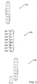
- Fig. 2 shows printing units having redundant nozzles and positioned parallel to the print direction helpful in demonstrating embodiments of the invention
- Fig. 3 is a flowchart diagram illustrating a method for printing according to some embodiments of the present invention.
- Embodiments of the invention may be applicable to a variety of printing systems and methods.
- exemplary embodiments and references of non-contact material deposition systems will mostly be for the application of fabrication of conducting metal lines for solar cells using an inkjet system.
- the scope of the invention is not limited by such exemplary embodiments and may be applied to other deposition systems, such an aerosol jet deposition system or a dispenser and to other applications, such as graphics, press, mass media, packaging, electronics and others.
- the invention and embodiments thereof are directed to a system and method for inspection of print nozzles while a print process or a print job is in progress and replacing actively printing nozzles as needed.
- the system comprises redundant print heads or printing units such that the number of print heads is higher than the number of print head required to perform a desired printing task. At any given time during printing a portion of the heads may be active while the remaining print head(s) may be redundant.
- a first subset selected from a plurality of print heads installed in a system would be designated to deposit material on a substrate
- a second, different subset of print heads may be subjected to, or undergo a maintenance procedure.
- a first print head is actively depositing material on a substrate
- a second print head may be relocated from a printing area or zone to an inspection, service or maintenance area. While the second print head is being inspected, serviced, repaired or otherwise subjected to a maintenance procedure, the first print head may continue to print and/or deposit material.
- the method may include printing lines on a substrate, for example printing contact lines on a semiconductor wafer by depositing material from a printing unit having nozzles arranged in one or more rows.
- the printing unit may comprise redundant nozzles.
- the number of nozzles in a printing unit is larger than the number of nozzles needed to accomplish a desired printing task, for example printing a line at a desired resolution.
- a portion of the nozzles within a printing unit is active while the remaining nozzles are redundant or inactive.
- the printing is done only by nozzles designated as active nozzles while the remaining nozzles are designated as inactive nozzles.
- material may be selectively deposited
- the method may further include moving the printing unit to an inspection zone while continuing the printing with active nozzles of another printing unit, which may perform the tasks of the former printing unit.
- the nozzles are inspected and one of the active nozzles may be identified as a faulty nozzle.
- the inspection may be done at the printing zone without moving the printing unit to the inspection zone.
- the identified faulty nozzle may be designated as inactive and one of the previously designated as inactive nozzles may become an active nozzle to replace the faulty nozzle.
- the method may further include moving the printing unit back from the inspection zone to the printing zone and continue printing with that unit such that the new active nozzle would replace the faulty nozzle.
- the system may analyze the inspection data and may choose a best set of nozzles to be the active nozzles based on predetermined considerations. Then, the chosen nozzles may be designated or specified as active nozzles while the remaining nozzles of the printing unit would be designated as inactive. Determining the best set of nozzles may be based on a required droplet size, stability of jetting and/or choosing nozzles having substantially similar deviation of their jetting direction from a normal to the nozzle plate (orifice plate). Other parameters may be taken into consideration for choosing the best set of nozzles without departing from the scope of the invention.
- system 100 may be capable of executing continuous high speed, high volume print jobs without frequently stopping for maintenance or inspection. It will be noted that system 100 may be applicable to a variety of printing systems, e.g., inkjet or aerosol dispensing systems.
- System 100 may include printing units or print heads 105A-105F, a printing zone 110, such as a conveyor or platform (not shown) defining the width of a print area, on which print media, such as semiconductor wafers may be placed and a service zone 125, in which maintenance and inspection of the printing units and their nozzles may take place.
- Service zone 125 may include one or more maintenance stations to perform various maintenance operations to the printing units. Although only six exemplary printing units are shown, any applicable number of printing units may be used without departing from the scope of the invention. The number of printing units is determined such that at least one printing unit is redundant. The redundancy enables the simultaneous inspection of non-active nozzles when active nozzles continue with the printing process. Accordingly, at least one printing unit from units 105A - 105F may be capable of independently moving between printing zone 110 and service zone 125 while the other printing units remain at the printing zone and continue with the printing process. Service zone 125 may be near or in close proximity to printing zone 110. According to some embodiments of the invention, printing units 105A-F may be mounted on rails such that they may be moved from printing zone 110 to service zone 125. Any other transport units or mechanisms may be used without departing from the scope of the invention.
- Each printing unit 105A-F comprises nozzles 106 arranged in one or more rows.
- each row has eight nozzles arranged in parallel to the printing or scanning direction X.
- each tow may include tens or hundreds of nozzles.
- Each row includes redundant nozzles for substitution of faulty nozzles upon detection.
- a faulty nozzle may be, for example, a clogged nozzle that cannot jet any material, a weak or partially clogged nozzle that can jet only a portion from the desired amount of material or a nozzle that jet in a direction that strongly deviates from the direction of jetting of the majority of the nozzles.
- Printing units 105A-C may be positioned in proximity to printing zone 110 such that the rows would be parallel to the print direction X. If the substrate is moved by a conveyor, the printing direction may be represented by the direction of advance of the substrate. In such a configuration, each row may print a single metallization line in a direction parallel to the print direction in one scan. Other setups or configurations of the printing unit with respect to the print direction are possible according to other embodiments of the invention.
- System 100 may further include a controller 115 to control the printing process and an image acquisition unit 120 coupled to controller 115.
- controller 115 may perform, or be involved in, tasks or functions such as, but not limited to, coordination, configuration, scheduling, arbitration, supervising, operation and/or management of components of system 100 and their operations.
- controller 115 may control the movement of printing units 105A-F and the printed objects in printing zone 110.
- Controller 115 may comprise any required or suitable hardware, software, firmware or a combination thereof.
- controller 115 may be a computing device comprising a controller and/or central processing unit (CPU), a memory and input and output units.
- CPU central processing unit
- Image acquisition unit 120 may comprise a detector or imaging device 121, such as camera or charge coupled device (CCD) to inspect the status and condition of the nozzles by acquiring, for example, images of droplets of material that exits the nozzles. Any other suitable visual detector or any other method of identifying the status of the nozzles may be used. Image acquisition unit 120 may further comprise an image processing unit 122 to analyze the images and determine the current status of the inspected nozzles and storage 123 to store data related to the status of the nozzles.
- CCD charge coupled device
- detector 121 may be coupled to a dedicated computing and storage device for processing and storing the captured images or alternatively controller 115 may perform these operations.
- a pulsed light source such as a pulsed laser source or a pulsed light emitting diode (LED) may be coupled to detector 121 to enable imaging of droplets being deposited from the nozzles.
- Controller 115 may further control and manage the inspection procedure, for example coordinating the ejection of droplets, the light pulses and the operation of the camera.
- Printing units 210, 220 and 230 may be used to print conductive lines on a semiconductor wafer in the production of solar cells.
- a first subset of nozzles may be designated as active nozzles, for example, nozzles 224-228 may be designated as active.
- a second subset of nozzles within printing unit 220, for example, nozzles 221-223 may be designated as inactive.
- the defective nozzle may be substituted by any one of the inactive nozzles 221-223.
- nozzle 225 may be re-designated as inactive and nozzle 222 may be re-designated as active.
- a print process while a print process is in progress and while one or more printing units defining a first subset of printing units is actively depositing, another one or more printing units defining a second subset of printing units may move to service zone 125 for maintenance and/or inspection. Further, if desired, the status of at least one pair of nozzles may be interchanged such that the previously active nozzle would become inactive and the previously inactive nozzle would become active.
- the printing units relocated to service zone 125 may be inspected, serviced and configured.
- nozzles may be inspected by acquiring images of droplets dispensed or ejected by nozzles of the inspected unit. The images may then be analyzed by image processing unit 122. Based on the analysis, faulty nozzles may be identified and replaced by redundant nozzles. Further, various working parameters may be modified or verified. For example, based on the inspection of a nozzle, working parameters such as pressure, temperature or voltage may be modified.
- image processing unit 122 may receive images from detector 121 and process such images by applying any suitable image processing techniques. For example, analysis of shape, trajectory and velocity of jetted droplets may be performed by the image processing unit. For example, image processing may be used to determine a condition of a nozzle based on an image of droplets being ejected from the nozzle. Another example may be comparing two or more images, possibly acquired over a predefined period of time. By comparing or otherwise relating images, various conditions, faults or other aspects of a nozzle may be determined. For example, degradation in the performance of a nozzle may be detected by comparing consecutive or successive images.
- detector 121 may be an infrared camera that may record temperatures, thus providing a temperature distribution of ejected ink or aerosol. While as described herein, imaging device or detector 121 may be placed at the service area, other configurations are possible. For example, one or more cameras may be placed near, around or in proximity of a printing area, e.g., area 110. Such cameras may obtain images during the printing process of nozzles depositing material onto a test substrate.
- Storage system or unit 123 may receive and store images acquired by detector 121 and/or obtained from a different source, e.g., a remote server or a removable storage media such as a compact disk (CD) or memory chip.
- a different source e.g., a remote server or a removable storage media such as a compact disk (CD) or memory chip.
- reference images of a desired ejection may be loaded into or otherwise stored in a storage device and may be used for comparing with or otherwise relating to images acquired by detector 121.
- a reference image may contain an image of an ideal, otherwise desirable ejection or deposition and thus may be used, for example by comparing it to a second image in order to determine if an injection imaged in the second image is acceptable or otherwise determine a quality of the ejection or other functional parameters related to the nozzle from which the imaged droplet has jetted.
- the redundancy of the printing unit or print heads may enable dynamically selecting the print heads that participate in a print process. Accordingly, redundant, spare, unused or idle print heads may exist and/or be available during a print process. Such redundant print heads may enable dynamic replacement of print heads while a print process is ongoing, active or in progress. For example, if a first print head is active, e.g., actively participating in a print process by depositing material on a media, needs, or is selected to be serviced or inspected, a second, inactive, idle or redundant print head may replace the first print head by being made active. Accordingly, the first print head, now being replaced, may be made inactive and may further be inspected, serviced or be otherwise subjected to a maintenance procedure.
- a first print head is active, e.g., actively participating in a print process by depositing material on a media, needs, or is selected to be serviced or inspected
- a second, inactive, idle or redundant print head may replace the first print head by being made active
- the printing units or print heads is equipped with redundant nozzles.
- a print head that may require one hundred (100) nozzles in order to perform its intended tasks may be equipped with five hundred (500) nozzles.
- redundancy of nozzles as described herein may enable dynamically selecting or designating a subset of nozzles as active. Such redundancy may further enable replacing active nozzles by inactive ones.
- a second, inactive or redundant nozzle may be selected, made active, and may replace the first nozzle by ejecting material onto a surface or media.
- the method may include commencing a print process using a first printing unit or print head.
- information in a print file may be provided to a printing system such as system 100 described in Fig. 1 .
- controller 115 may cause a conveyor to locate wafers such that a subset of nozzles, designated as active nozzles in both printing units 230 and 220 may deposit conductive material on them.
- controller 115 may control the nozzles and printing units such that material is deposited according to specifications or parameters in the print file.
- the method may include moving the one or more printing units, for example printing unit 220 to a service zone. During the time that the printing unit is being inspected and/or serviced at the service zone, another printing unit, such as printing unit 210 that was previously redundant may become active so that the printing process may continue with printing units 210 and 230. As shown by block 330, the method may include inspecting the nozzles of printing unit 200 and identifying one or more nozzles, for example nozzle 225 as faulty or defective nozzle.
- the method may include determining whether the fault can be repaired. For example, if a total obstruction of a nozzle's orifice is detected, a procedure may exist to remove the obstructions from the orifice thus repairing the fault. Other detected faults may be such that require a complex, possibly manual procedure in order to be fixed. Classifying a fault as one that may be handled or repaired immediately or while a print process is in progress may be according to various parameters and/or configurations. If the fault may be repaired, flow may include servicing the nozzle. For example, the working parameters may be modified or an automated purging procedure may be executed.
- the method may include choosing a best set of nozzles as best nozzles based on the inspection. Accordingly, the method may include designating a faulty nozzle as inactive when repair is impossible or undesirable. Nozzles identified as inactive may not participate in the printing process until their status is changed to "active". As shown by block 340, the method may comprise designating the nozzles of the chosen set as active and the faulty nozzles and remaining nozzles of the printing unit as inactive. For example, the method may include designating a nozzle, from the same row of the newly faulty nozzle that was previously designated an inactive nozzle as active. For example, after determining that nozzle 225 is faulty, a redundant nozzle that was previously inactive and did not participate in the printing process, such as nozzle 223 may be designated as an active nozzle that would replace the faulty nozzle 225.
- a first, faulty nozzle may be designated as inactive and a second, inactive nozzle may be designated as active in order to compensate for the faulty nozzle
- nozzles within the same printing unit and possibly the same row may be replaced based on a predefined schedule.
- nozzles may be designated as active or inactive periodically.
- a first nozzle may be replaced by a second nozzle
- other combinations are possible.
- a faulty nozzle may be replaced by two redundant nozzles. For example, such two nozzles may be instructed such that their combined operation is the same as an expected operation of the faulty, replaced nozzle.
- the method may include after the inspection is over, moving the first printing unit back to the printing zone.
- printing unit 220 may replace, for example, printing unit 210 in performing the ongoing print process and printing unit 210 may be moved to the service area for inspection.
- printing unit 220 may replace, for example, printing unit 230 in performing the ongoing print process and printing unit 230 may be moved to the service area for inspection.
- the method may comprise ceasing to print with a working printing unit and continuing with the print process using the first printing unit.
- the first printing unit may be for example, unit 220 in which the newly active nozzle, nozzle 221 replaces the previously used and now faulty nozzle 225.
- Embodiments of the invention may include an article such as a computer or processor readable medium, or a computer or processor storage medium, such as for example a memory, a disk drive, or a USB flash memory, encoding, including or storing instructions, e.g., computer-executable instructions, which when executed by a processor or controller, carry out methods disclosed herein.
- an article such as a computer or processor readable medium, or a computer or processor storage medium, such as for example a memory, a disk drive, or a USB flash memory, encoding, including or storing instructions, e.g., computer-executable instructions, which when executed by a processor or controller, carry out methods disclosed herein.
- the terms “plurality” and “a plurality” as used herein may include, for example, “multiple” or “two or more”.
- the terms “plurality” or “a plurality” may be used throughout the specification to describe two or more components, devices, elements, units, parameters, or the like.
- the method embodiments described herein are not constrained to a particular order or sequence. Additionally, some of the described method embodiments or elements thereof can occur or be performed at the same point in time or overlapping points in time.
- an execution of an executable code segment such as a function, task, sub-task or program may be referred to as execution of the function, program or other component.
Landscapes
- Engineering & Computer Science (AREA)
- Quality & Reliability (AREA)
- Application Of Or Painting With Fluid Materials (AREA)
- Ink Jet (AREA)
- Coating Apparatus (AREA)
- Manufacturing Of Printed Wiring (AREA)
Abstract
Description
- Non-contact material deposition printing is an appealing method for patterning and depositing materials in the printed electronics and solar cell industries. For example, forming conductive lines by directly depositing conductive materials on the back or front surface of the solar cell to provide a conduction path for the charge generated by the cell may increase the efficiency of the solar cell as well as the productivity of mass-manufacturing.
- Deposition printing techniques, such as ink jet printing or aerosol printing involves depositing droplets of print material from nozzles by moving a print head and a substrate relative to one another along a printing direction. One of the problems associated with deposition printing is faulty nozzles that may stop jetting or may jet poorly. Accordingly, a faulty nozzle may result in uneven conductive lines which may lead to inefficient or inoperative solar cells.
- The subject matter regarded as the invention is particularly pointed out and distinctly claimed in the concluding portion of the specification. Document
WO 2008/065657 defines the preamble of the first claim. The invention, however, both as to organization and method of operation, together with objects, features and advantages thereof, may best be understood by reference to the following detailed description when read with the accompanied drawings in which: -
Fig. 1 shows an exemplary printing system according to embodiments of the invention; -
Fig. 2 shows printing units having redundant nozzles and positioned parallel to the print direction helpful in demonstrating embodiments of the invention; and -
Fig. 3 is a flowchart diagram illustrating a method for printing according to some embodiments of the present invention. - It will be appreciated that for simplicity and clarity of illustration, elements shown in the figures have not necessarily been drawn to scale. For example, the dimensions of some of the elements may be exaggerated relative to other elements for clarity. Further, where considered appropriate, reference numerals may be repeated among the figures to indicate corresponding or analogous elements.
- In the following detailed description, numerous specific details are set forth in order to provide a thorough understanding of the invention. However, it will be understood by those of ordinary skill in the art that the invention may be practiced without these specific details. In other instances, well-known methods, procedures, components, modules, units and/or circuits have not been described in detail so as not to obscure the invention.
- Embodiments of the invention may be applicable to a variety of printing systems and methods. For the sake of clarity and simplicity exemplary embodiments and references of non-contact material deposition systems will mostly be for the application of fabrication of conducting metal lines for solar cells using an inkjet system. However, the scope of the invention is not limited by such exemplary embodiments and may be applied to other deposition systems, such an aerosol jet deposition system or a dispenser and to other applications, such as graphics, press, mass media, packaging, electronics and others.
- The invention and embodiments thereof are directed to a system and method for inspection of print nozzles while a print process or a print job is in progress and replacing actively printing nozzles as needed. According to the invention, the system comprises redundant print heads or printing units such that the number of print heads is higher than the number of print head required to perform a desired printing task. At any given time during printing a portion of the heads may be active while the remaining print head(s) may be redundant.
- According, while a print process is in progress, a first subset selected from a plurality of print heads installed in a system would be designated to deposit material on a substrate, a second, different subset of print heads may be subjected to, or undergo a maintenance procedure. For example, while a first print head is actively depositing material on a substrate, a second print head may be relocated from a printing area or zone to an inspection, service or maintenance area. While the second print head is being inspected, serviced, repaired or otherwise subjected to a maintenance procedure, the first print head may continue to print and/or deposit material.
- In some embodiments, the method may include printing lines on a substrate, for example printing contact lines on a semiconductor wafer by depositing material from a printing unit having nozzles arranged in one or more rows. According to the invention, the printing unit may comprise redundant nozzles. The number of nozzles in a printing unit is larger than the number of nozzles needed to accomplish a desired printing task, for example printing a line at a desired resolution. At any given time during printing, a portion of the nozzles within a printing unit is active while the remaining nozzles are redundant or inactive. The printing is done only by nozzles designated as active nozzles while the remaining nozzles are designated as inactive nozzles. Within a particular row, material may be selectively deposited
- The method may further include moving the printing unit to an inspection zone while continuing the printing with active nozzles of another printing unit, which may perform the tasks of the former printing unit. In the inspection zone the nozzles are inspected and one of the active nozzles may be identified as a faulty nozzle. According to some embodiments, the inspection may be done at the printing zone without moving the printing unit to the inspection zone.
- Then, the identified faulty nozzle may be designated as inactive and one of the previously designated as inactive nozzles may become an active nozzle to replace the faulty nozzle. The method may further include moving the printing unit back from the inspection zone to the printing zone and continue printing with that unit such that the new active nozzle would replace the faulty nozzle.
- According to embodiments of the invention, after all the nozzles are inspected in the inspection zone or the printing zone, the system may analyze the inspection data and may choose a best set of nozzles to be the active nozzles based on predetermined considerations. Then, the chosen nozzles may be designated or specified as active nozzles while the remaining nozzles of the printing unit would be designated as inactive. Determining the best set of nozzles may be based on a required droplet size, stability of jetting and/or choosing nozzles having substantially similar deviation of their jetting direction from a normal to the nozzle plate (orifice plate). Other parameters may be taken into consideration for choosing the best set of nozzles without departing from the scope of the invention.
- Reference is made to
Fig. 1 showing a high-level block diagram of an exemplary printing system according to exemplary embodiments of the invention. The exemplary system,denoted system 100 may be capable of executing continuous high speed, high volume print jobs without frequently stopping for maintenance or inspection. It will be noted thatsystem 100 may be applicable to a variety of printing systems, e.g., inkjet or aerosol dispensing systems.System 100 may include printing units orprint heads 105A-105F, aprinting zone 110, such as a conveyor or platform (not shown) defining the width of a print area, on which print media, such as semiconductor wafers may be placed and aservice zone 125, in which maintenance and inspection of the printing units and their nozzles may take place. -
Service zone 125 may include one or more maintenance stations to perform various maintenance operations to the printing units. Although only six exemplary printing units are shown, any applicable number of printing units may be used without departing from the scope of the invention. The number of printing units is determined such that at least one printing unit is redundant. The redundancy enables the simultaneous inspection of non-active nozzles when active nozzles continue with the printing process. Accordingly, at least one printing unit fromunits 105A - 105F may be capable of independently moving betweenprinting zone 110 andservice zone 125 while the other printing units remain at the printing zone and continue with the printing process.Service zone 125 may be near or in close proximity toprinting zone 110. According to some embodiments of the invention,printing units 105A-F may be mounted on rails such that they may be moved fromprinting zone 110 toservice zone 125. Any other transport units or mechanisms may be used without departing from the scope of the invention. - Each
printing unit 105A-F comprisesnozzles 106 arranged in one or more rows. In the exemplary illustration ofFig. 1 , each row has eight nozzles arranged in parallel to the printing or scanning direction X. However, it will be appreciated by those skilled in the art that each tow may include tens or hundreds of nozzles. Each row includes redundant nozzles for substitution of faulty nozzles upon detection. A faulty nozzle may be, for example, a clogged nozzle that cannot jet any material, a weak or partially clogged nozzle that can jet only a portion from the desired amount of material or a nozzle that jet in a direction that strongly deviates from the direction of jetting of the majority of the nozzles. -
Printing units 105A-C may be positioned in proximity toprinting zone 110 such that the rows would be parallel to the print direction X. If the substrate is moved by a conveyor, the printing direction may be represented by the direction of advance of the substrate. In such a configuration, each row may print a single metallization line in a direction parallel to the print direction in one scan. Other setups or configurations of the printing unit with respect to the print direction are possible according to other embodiments of the invention. -
System 100 may further include acontroller 115 to control the printing process and animage acquisition unit 120 coupled tocontroller 115. According to embodiments of the invention,controller 115 may perform, or be involved in, tasks or functions such as, but not limited to, coordination, configuration, scheduling, arbitration, supervising, operation and/or management of components ofsystem 100 and their operations. For example,controller 115 may control the movement ofprinting units 105A-F and the printed objects inprinting zone 110.Controller 115 may comprise any required or suitable hardware, software, firmware or a combination thereof. For example,controller 115 may be a computing device comprising a controller and/or central processing unit (CPU), a memory and input and output units. -
Image acquisition unit 120 may comprise a detector orimaging device 121, such as camera or charge coupled device (CCD) to inspect the status and condition of the nozzles by acquiring, for example, images of droplets of material that exits the nozzles. Any other suitable visual detector or any other method of identifying the status of the nozzles may be used.Image acquisition unit 120 may further comprise animage processing unit 122 to analyze the images and determine the current status of the inspected nozzles andstorage 123 to store data related to the status of the nozzles. - According to embodiments of the invention,
detector 121 may be coupled to a dedicated computing and storage device for processing and storing the captured images or alternativelycontroller 115 may perform these operations. According to embodiments of the invention, a pulsed light source, such as a pulsed laser source or a pulsed light emitting diode (LED) may be coupled todetector 121 to enable imaging of droplets being deposited from the nozzles.Controller 115 may further control and manage the inspection procedure, for example coordinating the ejection of droplets, the light pulses and the operation of the camera. - Reference is now made to
Fig. 2 , which illustrates an array of printing units having redundant nozzles and positioned parallel to the print direction to demonstrate embodiments of the invention.Printing units printing unit 220, for example, nozzles 221-223 may be designated as inactive. Upon identifying that a nozzle, for example,nozzle 225 is defective, the defective nozzle may be substituted by any one of the inactive nozzles 221-223. For example,nozzle 225 may be re-designated as inactive and nozzle 222 may be re-designated as active. - According to embodiments of the invention, while a print process is in progress and while one or more printing units defining a first subset of printing units is actively depositing, another one or more printing units defining a second subset of printing units may move to
service zone 125 for maintenance and/or inspection. Further, if desired, the status of at least one pair of nozzles may be interchanged such that the previously active nozzle would become inactive and the previously inactive nozzle would become active. - The printing units relocated to
service zone 125 may be inspected, serviced and configured. For example, nozzles may be inspected by acquiring images of droplets dispensed or ejected by nozzles of the inspected unit. The images may then be analyzed byimage processing unit 122. Based on the analysis, faulty nozzles may be identified and replaced by redundant nozzles. Further, various working parameters may be modified or verified. For example, based on the inspection of a nozzle, working parameters such as pressure, temperature or voltage may be modified. - Referring back to
Fig. 1 ,image processing unit 122 may receive images fromdetector 121 and process such images by applying any suitable image processing techniques. For example, analysis of shape, trajectory and velocity of jetted droplets may be performed by the image processing unit. For example, image processing may be used to determine a condition of a nozzle based on an image of droplets being ejected from the nozzle. Another example may be comparing two or more images, possibly acquired over a predefined period of time. By comparing or otherwise relating images, various conditions, faults or other aspects of a nozzle may be determined. For example, degradation in the performance of a nozzle may be detected by comparing consecutive or successive images. - While a video camera may provide images related to visible light, other images may be produced. For example,
detector 121 may be an infrared camera that may record temperatures, thus providing a temperature distribution of ejected ink or aerosol. While as described herein, imaging device ordetector 121 may be placed at the service area, other configurations are possible. For example, one or more cameras may be placed near, around or in proximity of a printing area, e.g.,area 110. Such cameras may obtain images during the printing process of nozzles depositing material onto a test substrate. - Storage system or
unit 123 may receive and store images acquired bydetector 121 and/or obtained from a different source, e.g., a remote server or a removable storage media such as a compact disk (CD) or memory chip. For example, reference images of a desired ejection may be loaded into or otherwise stored in a storage device and may be used for comparing with or otherwise relating to images acquired bydetector 121. A reference image may contain an image of an ideal, otherwise desirable ejection or deposition and thus may be used, for example by comparing it to a second image in order to determine if an injection imaged in the second image is acceptable or otherwise determine a quality of the ejection or other functional parameters related to the nozzle from which the imaged droplet has jetted. - It should be appreciated by those skilled in the art that the redundancy of the printing unit or print heads may enable dynamically selecting the print heads that participate in a print process. Accordingly, redundant, spare, unused or idle print heads may exist and/or be available during a print process. Such redundant print heads may enable dynamic replacement of print heads while a print process is ongoing, active or in progress. For example, if a first print head is active, e.g., actively participating in a print process by depositing material on a media, needs, or is selected to be serviced or inspected, a second, inactive, idle or redundant print head may replace the first print head by being made active. Accordingly, the first print head, now being replaced, may be made inactive and may further be inspected, serviced or be otherwise subjected to a maintenance procedure.
- According to embodiments of the invention, the printing units or print heads is equipped with redundant nozzles. For example, a print head that may require one hundred (100) nozzles in order to perform its intended tasks may be equipped with five hundred (500) nozzles. Accordingly, only a subset of nozzles fitted, included or installed in a print head may actively participate in a print process, e.g., actually eject material onto a surface or media. According to embodiments of the invention, redundancy of nozzles as described herein may enable dynamically selecting or designating a subset of nozzles as active. Such redundancy may further enable replacing active nozzles by inactive ones. For example, upon determining that a first nozzle in a print head needs to be replaced or serviced, e.g., due to a malfunction or as part of a scheduled or periodic maintenance routine, a second, inactive or redundant nozzle may be selected, made active, and may replace the first nozzle by ejecting material onto a surface or media.
- Reference is made to
Fig. 3 showing a flowchart diagram illustrating a method for printing according to some embodiments of the present invention. As shown byblock 310, the method may include commencing a print process using a first printing unit or print head. For example, information in a print file may be provided to a printing system such assystem 100 described inFig. 1 . Provided with such information,controller 115 may cause a conveyor to locate wafers such that a subset of nozzles, designated as active nozzles in both printingunits controller 115 may control the nozzles and printing units such that material is deposited according to specifications or parameters in the print file. - As shown by
block 320, the method may include moving the one or more printing units, forexample printing unit 220 to a service zone. During the time that the printing unit is being inspected and/or serviced at the service zone, another printing unit, such asprinting unit 210 that was previously redundant may become active so that the printing process may continue withprinting units block 330, the method may include inspecting the nozzles of printing unit 200 and identifying one or more nozzles, forexample nozzle 225 as faulty or defective nozzle. - The method may include determining whether the fault can be repaired. For example, if a total obstruction of a nozzle's orifice is detected, a procedure may exist to remove the obstructions from the orifice thus repairing the fault. Other detected faults may be such that require a complex, possibly manual procedure in order to be fixed. Classifying a fault as one that may be handled or repaired immediately or while a print process is in progress may be according to various parameters and/or configurations. If the fault may be repaired, flow may include servicing the nozzle. For example, the working parameters may be modified or an automated purging procedure may be executed.
- As shown by
block 335, the method may include choosing a best set of nozzles as best nozzles based on the inspection. Accordingly, the method may include designating a faulty nozzle as inactive when repair is impossible or undesirable. Nozzles identified as inactive may not participate in the printing process until their status is changed to "active". As shown byblock 340, the method may comprise designating the nozzles of the chosen set as active and the faulty nozzles and remaining nozzles of the printing unit as inactive. For example, the method may include designating a nozzle, from the same row of the newly faulty nozzle that was previously designated an inactive nozzle as active. For example, after determining thatnozzle 225 is faulty, a redundant nozzle that was previously inactive and did not participate in the printing process, such asnozzle 223 may be designated as an active nozzle that would replace thefaulty nozzle 225. - While as described herein, a first, faulty nozzle may be designated as inactive and a second, inactive nozzle may be designated as active in order to compensate for the faulty nozzle, other scenarios are possible. For example, nozzles within the same printing unit and possibly the same row may be replaced based on a predefined schedule. For example, in order to avoid drying of ink in nozzles, nozzles may be designated as active or inactive periodically. While in some embodiments a first nozzle may be replaced by a second nozzle, other combinations are possible. For example, a faulty nozzle may be replaced by two redundant nozzles. For example, such two nozzles may be instructed such that their combined operation is the same as an expected operation of the faulty, replaced nozzle.
- As shown by
block 345, the method may include after the inspection is over, moving the first printing unit back to the printing zone. As other print heads may be printing at such time,printing unit 220 may replace, for example, printingunit 210 in performing the ongoing print process andprinting unit 210 may be moved to the service area for inspection. Alternatively, printingunit 220 may replace, for example, printingunit 230 in performing the ongoing print process andprinting unit 230 may be moved to the service area for inspection. Accordingly, as shown byblock 350, the method may comprise ceasing to print with a working printing unit and continuing with the print process using the first printing unit. The first printing unit may be for example,unit 220 in which the newly active nozzle,nozzle 221 replaces the previously used and nowfaulty nozzle 225. - Embodiments of the invention may include an article such as a computer or processor readable medium, or a computer or processor storage medium, such as for example a memory, a disk drive, or a USB flash memory, encoding, including or storing instructions, e.g., computer-executable instructions, which when executed by a processor or controller, carry out methods disclosed herein.
- Although embodiments of the invention are not limited in this regard, the terms "plurality" and "a plurality" as used herein may include, for example, "multiple" or "two or more". The terms "plurality" or "a plurality" may be used throughout the specification to describe two or more components, devices, elements, units, parameters, or the like.
- Unless explicitly stated, the method embodiments described herein are not constrained to a particular order or sequence. Additionally, some of the described method embodiments or elements thereof can occur or be performed at the same point in time or overlapping points in time. As known in the art, an execution of an executable code segment such as a function, task, sub-task or program may be referred to as execution of the function, program or other component.
- Although embodiments of the invention are not limited in this regard, discussions utilizing terms such as, for example, "processing," "computing," "calculating," "determining," "establishing", "analyzing", "checking", or the like, may refer to operation(s) and/or process(es) of a computer, a computing platform, a computing system, or other electronic computing device, that manipulate and/or transform data represented as physical (e.g., electronic) quantities within the computer's registers and/or memories into other data similarly represented as physical quantities within the computer's registers and/or memories or other information storage medium that may store instructions to perform operations and/or processes.
- While certain features of the invention have been illustrated and described herein, many modifications, substitutions, changes, and equivalents may occur to those skilled in the art. It is, therefore, to be understood that the appended claims are intended to cover all such modifications and changes as fall within the true spirit of the invention.
Claims (12)
- A method of printing, the method comprising:printing in a printing zone using a first printing unit (220) having nozzles, a first portion of the nozzles is designated as active nozzles (224-228) and a second portion of the nozzles is designated as inactive nozzles (221-223), wherein the printing is done by selectively depositing material from the active nozzles of the first printing unit;stopping the printing with the first printing unit while continuing the printing with active nozzles of a second printing unit (210, 230),inspecting the nozzles of the first printing unit;choosing a new set of active nozzles based on inspection results; andcontinuing the printing using the first printing unit (220) with the new set of active nozzles;characterised in that the nozzles are arranged in a row having a direction parallel to the scanning direction.
- The method of claim 1 comprising:moving the first printing unit to an inspection zone prior to inspecting; andmoving the first printing unit back to the printing zone for continuing the printing.
- The method of claim 1, wherein printing comprises printing a line in a scanning direction.
- The method of claim 1 comprising:identifying one of the active nozzles of the first printing unit as a faulty nozzle;designating the faulty nozzle as inactive and designating one of the inactive nozzles of the first printing unit as a new active nozzle, so as the new active nozzle replaces the faulty nozzle.
- The method of claim 1, wherein inspecting comprises:acquiring images of ejections of droplets performed by the nozzles of the first printing unit; andidentifying the faulty nozzle based on an analysis of the images.
- The method of claim 5, wherein the analysis comprises determining the size of droplets and the size of deviation of a jetting direction from a predetermined direction.
- The method of claim 1, wherein depositing is depositing an electrically conductive material on one of a printed card board or a semiconductor wafer to produce metallization conduction lines.
- The method of claim 1, wherein the new set of active nozzles is chosen based on a required droplet size.
- The method of claim 1, wherein the new set of active nozzles is chosen based on the degree of stability of jetting from the nozzles.
- The method of claim 1, wherein the new set of active nozzles is chosen based the jetting direction of the nozzles.
- The method of claim 1 comprising:inspecting at least a portion of the nozzles; andanalyzing inspection data.
- The method of claim 11, wherein analyzing the inspection data comprises determining the size of droplets ejected from the nozzles and the size of deviation of a jetting direction from a predetermined direction.
Applications Claiming Priority (2)
| Application Number | Priority Date | Filing Date | Title |
|---|---|---|---|
| US7388908P | 2008-06-19 | 2008-06-19 | |
| PCT/IL2009/000612 WO2009153795A1 (en) | 2008-06-19 | 2009-06-18 | Method and system for nozzle compensation in non-contact material deposition |
Publications (2)
| Publication Number | Publication Date |
|---|---|
| EP2313277A1 EP2313277A1 (en) | 2011-04-27 |
| EP2313277B1 true EP2313277B1 (en) | 2012-05-09 |
Family
ID=41151904
Family Applications (1)
| Application Number | Title | Priority Date | Filing Date |
|---|---|---|---|
| EP09766330A Not-in-force EP2313277B1 (en) | 2008-06-19 | 2009-06-18 | Method and system for nozzle compensation in non-contact material deposition |
Country Status (7)
| Country | Link |
|---|---|
| EP (1) | EP2313277B1 (en) |
| JP (2) | JP2011526199A (en) |
| KR (1) | KR101641392B1 (en) |
| CN (1) | CN102574396B (en) |
| AT (1) | ATE556851T1 (en) |
| TW (1) | TWI448390B (en) |
| WO (1) | WO2009153795A1 (en) |
Families Citing this family (15)
| Publication number | Priority date | Publication date | Assignee | Title |
|---|---|---|---|---|
| CN102574396B (en) * | 2008-06-19 | 2015-05-20 | 迅捷有限公司 | Method and system for nozzle compensation in non-contact material deposition |
| DK2472268T3 (en) | 2010-12-30 | 2013-03-04 | Alltec Angewandte Laserlicht Technologie Gmbh | Marking or scanning apparatus having a measuring device for measuring the velocity of an object and method for measuring the velocity of an object with such a marking or scanning apparatus |
| EP2472842B1 (en) | 2010-12-30 | 2020-03-04 | ALLTEC Angewandte Laserlicht Technologie Gesellschaft mit beschränkter Haftung | Sensor apparatus |
| DK2471665T3 (en) | 2010-12-30 | 2013-05-06 | Alltec Angewandte Laserlicht Technologie Gmbh | Selection and / or scanning head, device and method |
| DK2471663T3 (en) | 2010-12-30 | 2012-10-01 | Alltec Angewandte Laserlicht Technologie Gmbh | Method of applying a marking to an article and marking device |
| EP2471669B1 (en) | 2010-12-30 | 2013-07-10 | ALLTEC Angewandte Laserlicht Technologie Gesellschaft mit beschränkter Haftung | Marking apparatus |
| ES2398780T3 (en) | 2010-12-30 | 2013-03-21 | ALLTEC Angewandte Laserlicht Technologie Gesellschaft mit beschränkter Haftung | Surveillance device and monitoring procedure for marking elements of a marking head |
| EP2471658B1 (en) | 2010-12-30 | 2018-10-03 | ALLTEC Angewandte Laserlicht Technologie Gesellschaft mit beschränkter Haftung | Marking apparatus |
| EP2471666B1 (en) | 2010-12-30 | 2012-09-12 | ALLTEC Angewandte Laserlicht Technologie Gesellschaft mit beschränkter Haftung | Marking apparatus and method for operating a marking apparatus |
| EP2471664B1 (en) * | 2010-12-30 | 2013-04-24 | ALLTEC Angewandte Laserlicht Technologie Gesellschaft mit beschränkter Haftung | Device for marking and/or scanning an object |
| EP2472843B1 (en) | 2010-12-30 | 2018-11-07 | ALLTEC Angewandte Laserlicht Technologie Gesellschaft mit beschränkter Haftung | Method for controlling an apparatus for printing and/or scanning an object |
| JP5995929B2 (en) * | 2014-08-28 | 2016-09-21 | 富士フイルム株式会社 | Image recording apparatus and method |
| CN108068462B (en) * | 2018-01-03 | 2019-09-06 | 京东方科技集团股份有限公司 | Inkjet printing device and inkjet printing method |
| JP2020185524A (en) * | 2019-05-14 | 2020-11-19 | キヤノン株式会社 | Discharge material discharge device |
| US12337524B2 (en) | 2019-08-27 | 2025-06-24 | Peridot Print Llc | Modifying print data near and/or at overlap areas between printhead dies |
Family Cites Families (21)
| Publication number | Priority date | Publication date | Assignee | Title |
|---|---|---|---|---|
| US5587730A (en) * | 1994-09-30 | 1996-12-24 | Xerox Corporation | Redundant full width array thermal ink jet printing for improved reliability |
| JP2001044601A (en) * | 1999-07-30 | 2001-02-16 | Brother Ind Ltd | Printed circuit board wiring pattern forming equipment |
| JP3774638B2 (en) * | 2001-04-24 | 2006-05-17 | ハリマ化成株式会社 | Circuit pattern forming method using inkjet printing method |
| JP2004055965A (en) * | 2002-07-23 | 2004-02-19 | Seiko Epson Corp | Wiring board, semiconductor device, manufacturing method thereof, circuit board, and electronic equipment |
| JP4164305B2 (en) * | 2002-07-24 | 2008-10-15 | キヤノン株式会社 | Inkjet recording method and inkjet recording apparatus |
| JP3690380B2 (en) * | 2002-08-02 | 2005-08-31 | セイコーエプソン株式会社 | Material arrangement method, electronic device manufacturing method, electro-optical device manufacturing method |
| US7407264B2 (en) * | 2002-10-01 | 2008-08-05 | Sony Corporation | Liquid discharging apparatus and liquid discharging method |
| JP2004165035A (en) * | 2002-11-14 | 2004-06-10 | Seiko Epson Corp | Ejection inspection method and ejection inspection device for droplet ejection head in organic EL device manufacturing apparatus, and organic EL device manufacturing apparatus, organic EL device, organic EL device manufacturing method, and electronic equipment |
| JP2004237697A (en) * | 2003-02-10 | 2004-08-26 | Sony Corp | Liquid ejection device and liquid ejection method |
| EP1452319B1 (en) * | 2003-02-26 | 2015-10-21 | Océ-Technologies B.V. | Printing method and printer with failure compensation |
| KR100545288B1 (en) * | 2003-03-28 | 2006-01-25 | 주식회사 잉크테크 | Organic silver conpound and it's preparation method, organic silver ink and it's direct wiring method |
| JP2004321891A (en) * | 2003-04-23 | 2004-11-18 | Seiko Epson Corp | Droplet discharge device, method of manufacturing electro-optical device, electro-optical device, and electronic apparatus |
| JP2004338171A (en) * | 2003-05-14 | 2004-12-02 | Seiko Epson Corp | Drawing apparatus, drawing method, device and electronic apparatus |
| JP2005104037A (en) * | 2003-09-30 | 2005-04-21 | Fuji Photo Film Co Ltd | Image forming device and recording control method |
| US6942308B2 (en) * | 2003-10-10 | 2005-09-13 | Hewlett-Packard Development Company, L.P. | Compensation of lateral position changes in printing |
| JP2005193511A (en) * | 2004-01-07 | 2005-07-21 | Canon Inc | Inkjet array drawing device |
| JP2006187872A (en) * | 2004-12-28 | 2006-07-20 | Canon Inc | Inkjet recording apparatus and inkjet recording method |
| KR20060088373A (en) * | 2005-02-01 | 2006-08-04 | 엘지.필립스 엘시디 주식회사 | Inkjet Printing Equipment with Nozzle Monitoring Device |
| KR20060115125A (en) * | 2005-05-04 | 2006-11-08 | 삼성전자주식회사 | Inkjet Image Forming Device and Defective Nozzle Compensation Method |
| CN101663171B (en) * | 2006-11-28 | 2011-12-14 | Xjet有限公司 | Inkjet printing system with movable print heads and methods thereof |
| CN102574396B (en) * | 2008-06-19 | 2015-05-20 | 迅捷有限公司 | Method and system for nozzle compensation in non-contact material deposition |
-
2009
- 2009-06-18 CN CN200980123292.5A patent/CN102574396B/en not_active Expired - Fee Related
- 2009-06-18 AT AT09766330T patent/ATE556851T1/en active
- 2009-06-18 EP EP09766330A patent/EP2313277B1/en not_active Not-in-force
- 2009-06-18 WO PCT/IL2009/000612 patent/WO2009153795A1/en not_active Ceased
- 2009-06-18 KR KR1020117001294A patent/KR101641392B1/en not_active Expired - Fee Related
- 2009-06-18 JP JP2011514200A patent/JP2011526199A/en active Pending
- 2009-06-19 TW TW098120609A patent/TWI448390B/en not_active IP Right Cessation
-
2014
- 2014-07-10 JP JP2014142159A patent/JP5972937B2/en not_active Expired - Fee Related
Also Published As
| Publication number | Publication date |
|---|---|
| JP2011526199A (en) | 2011-10-06 |
| KR20110038675A (en) | 2011-04-14 |
| JP5972937B2 (en) | 2016-08-17 |
| ATE556851T1 (en) | 2012-05-15 |
| TWI448390B (en) | 2014-08-11 |
| JP2015006668A (en) | 2015-01-15 |
| TW201008788A (en) | 2010-03-01 |
| CN102574396B (en) | 2015-05-20 |
| WO2009153795A1 (en) | 2009-12-23 |
| EP2313277A1 (en) | 2011-04-27 |
| CN102574396A (en) | 2012-07-11 |
| KR101641392B1 (en) | 2016-07-20 |
Similar Documents
| Publication | Publication Date | Title |
|---|---|---|
| CN102574396B (en) | Method and system for nozzle compensation in non-contact material deposition | |
| US20180324959A1 (en) | Method and system for nozzle compensation in non-contact material deposition | |
| TWI410333B (en) | Inkjet printing system with movable print heads and methods thereof | |
| KR102017399B1 (en) | Fast measurement of droplet parameters in industrial printing system | |
| JP2020024943A (en) | Techniques for printing ink droplet measurement and control of depositing fluids within close tolerances | |
| KR101925672B1 (en) | Techniques for print ink droplet measurement and control to deposit fluids within precise tolerances | |
| US20190001666A1 (en) | Device and method for detecting ink droplet | |
| TWI686312B (en) | Method of fabricating thin-film layers of electronic products | |
| EP3002127B1 (en) | Image recording apparatus and method | |
| JP2019155307A (en) | Inkjet discharge inspection method and inkjet coating method | |
| TW202144194A (en) | Ink coating device, control device thereof, and inkjet head inspection method capable of suppressing an increase in the inspection time of nozzle quality | |
| JP5761896B2 (en) | Droplet application method and apparatus | |
| JP5834823B2 (en) | Liquid ejection inspection apparatus, liquid ejection inspection method, printing apparatus, and program | |
| US11400730B2 (en) | Systems and methods for predicting printing device failures or maintenance needs | |
| US20240198658A1 (en) | Control unit and substrate treating apparatus including the same | |
| US20240075740A1 (en) | Inkjet head unit and substrate treatment apparatus including the same | |
| US12552151B2 (en) | Substrate processing apparatus and method | |
| US12138913B2 (en) | Control unit and substrate treating apparatus including the same | |
| WO2010109457A1 (en) | Method and apparatus for print unit inspection and calibration | |
| JP2020536227A (en) | Methods and Devices for Creating Printed Microarrays | |
| KR20240140237A (en) | Bad nozzle prediction method and system using smart machine learning | |
| WO2023164395A1 (en) | Print head management accessories | |
| JP2011161394A (en) | Method for discharging droplet | |
| JP2013233742A (en) | Positioning method |
Legal Events
| Date | Code | Title | Description |
|---|---|---|---|
| PUAI | Public reference made under article 153(3) epc to a published international application that has entered the european phase |
Free format text: ORIGINAL CODE: 0009012 |
|
| 17P | Request for examination filed |
Effective date: 20110119 |
|
| AK | Designated contracting states |
Kind code of ref document: A1 Designated state(s): AT BE BG CH CY CZ DE DK EE ES FI FR GB GR HR HU IE IS IT LI LT LU LV MC MK MT NL NO PL PT RO SE SI SK TR |
|
| AX | Request for extension of the european patent |
Extension state: AL BA RS |
|
| 17Q | First examination report despatched |
Effective date: 20110721 |
|
| DAX | Request for extension of the european patent (deleted) | ||
| GRAP | Despatch of communication of intention to grant a patent |
Free format text: ORIGINAL CODE: EPIDOSNIGR1 |
|
| GRAS | Grant fee paid |
Free format text: ORIGINAL CODE: EPIDOSNIGR3 |
|
| GRAA | (expected) grant |
Free format text: ORIGINAL CODE: 0009210 |
|
| AK | Designated contracting states |
Kind code of ref document: B1 Designated state(s): AT BE BG CH CY CZ DE DK EE ES FI FR GB GR HR HU IE IS IT LI LT LU LV MC MK MT NL NO PL PT RO SE SI SK TR |
|
| REG | Reference to a national code |
Ref country code: GB Ref legal event code: FG4D |
|
| REG | Reference to a national code |
Ref country code: AT Ref legal event code: REF Ref document number: 556851 Country of ref document: AT Kind code of ref document: T Effective date: 20120515 Ref country code: CH Ref legal event code: EP |
|
| REG | Reference to a national code |
Ref country code: IE Ref legal event code: FG4D |
|
| REG | Reference to a national code |
Ref country code: DE Ref legal event code: R096 Ref document number: 602009006818 Country of ref document: DE Effective date: 20120712 |
|
| REG | Reference to a national code |
Ref country code: NL Ref legal event code: VDEP Effective date: 20120509 |
|
| REG | Reference to a national code |
Ref country code: LT Ref legal event code: MG4D Effective date: 20120509 |
|
| PG25 | Lapsed in a contracting state [announced via postgrant information from national office to epo] |
Ref country code: LT Free format text: LAPSE BECAUSE OF FAILURE TO SUBMIT A TRANSLATION OF THE DESCRIPTION OR TO PAY THE FEE WITHIN THE PRESCRIBED TIME-LIMIT Effective date: 20120509 Ref country code: CY Free format text: LAPSE BECAUSE OF FAILURE TO SUBMIT A TRANSLATION OF THE DESCRIPTION OR TO PAY THE FEE WITHIN THE PRESCRIBED TIME-LIMIT Effective date: 20120509 Ref country code: SE Free format text: LAPSE BECAUSE OF FAILURE TO SUBMIT A TRANSLATION OF THE DESCRIPTION OR TO PAY THE FEE WITHIN THE PRESCRIBED TIME-LIMIT Effective date: 20120509 Ref country code: PL Free format text: LAPSE BECAUSE OF FAILURE TO SUBMIT A TRANSLATION OF THE DESCRIPTION OR TO PAY THE FEE WITHIN THE PRESCRIBED TIME-LIMIT Effective date: 20120509 Ref country code: NO Free format text: LAPSE BECAUSE OF FAILURE TO SUBMIT A TRANSLATION OF THE DESCRIPTION OR TO PAY THE FEE WITHIN THE PRESCRIBED TIME-LIMIT Effective date: 20120809 Ref country code: IS Free format text: LAPSE BECAUSE OF FAILURE TO SUBMIT A TRANSLATION OF THE DESCRIPTION OR TO PAY THE FEE WITHIN THE PRESCRIBED TIME-LIMIT Effective date: 20120909 Ref country code: FI Free format text: LAPSE BECAUSE OF FAILURE TO SUBMIT A TRANSLATION OF THE DESCRIPTION OR TO PAY THE FEE WITHIN THE PRESCRIBED TIME-LIMIT Effective date: 20120509 |
|
| REG | Reference to a national code |
Ref country code: AT Ref legal event code: MK05 Ref document number: 556851 Country of ref document: AT Kind code of ref document: T Effective date: 20120509 |
|
| PG25 | Lapsed in a contracting state [announced via postgrant information from national office to epo] |
Ref country code: PT Free format text: LAPSE BECAUSE OF FAILURE TO SUBMIT A TRANSLATION OF THE DESCRIPTION OR TO PAY THE FEE WITHIN THE PRESCRIBED TIME-LIMIT Effective date: 20120910 Ref country code: HR Free format text: LAPSE BECAUSE OF FAILURE TO SUBMIT A TRANSLATION OF THE DESCRIPTION OR TO PAY THE FEE WITHIN THE PRESCRIBED TIME-LIMIT Effective date: 20120509 Ref country code: LV Free format text: LAPSE BECAUSE OF FAILURE TO SUBMIT A TRANSLATION OF THE DESCRIPTION OR TO PAY THE FEE WITHIN THE PRESCRIBED TIME-LIMIT Effective date: 20120509 Ref country code: GR Free format text: LAPSE BECAUSE OF FAILURE TO SUBMIT A TRANSLATION OF THE DESCRIPTION OR TO PAY THE FEE WITHIN THE PRESCRIBED TIME-LIMIT Effective date: 20120810 Ref country code: SI Free format text: LAPSE BECAUSE OF FAILURE TO SUBMIT A TRANSLATION OF THE DESCRIPTION OR TO PAY THE FEE WITHIN THE PRESCRIBED TIME-LIMIT Effective date: 20120509 |
|
| PG25 | Lapsed in a contracting state [announced via postgrant information from national office to epo] |
Ref country code: BE Free format text: LAPSE BECAUSE OF FAILURE TO SUBMIT A TRANSLATION OF THE DESCRIPTION OR TO PAY THE FEE WITHIN THE PRESCRIBED TIME-LIMIT Effective date: 20120509 |
|
| PG25 | Lapsed in a contracting state [announced via postgrant information from national office to epo] |
Ref country code: CZ Free format text: LAPSE BECAUSE OF FAILURE TO SUBMIT A TRANSLATION OF THE DESCRIPTION OR TO PAY THE FEE WITHIN THE PRESCRIBED TIME-LIMIT Effective date: 20120509 Ref country code: RO Free format text: LAPSE BECAUSE OF FAILURE TO SUBMIT A TRANSLATION OF THE DESCRIPTION OR TO PAY THE FEE WITHIN THE PRESCRIBED TIME-LIMIT Effective date: 20120509 Ref country code: SK Free format text: LAPSE BECAUSE OF FAILURE TO SUBMIT A TRANSLATION OF THE DESCRIPTION OR TO PAY THE FEE WITHIN THE PRESCRIBED TIME-LIMIT Effective date: 20120509 Ref country code: MC Free format text: LAPSE BECAUSE OF NON-PAYMENT OF DUE FEES Effective date: 20120630 Ref country code: NL Free format text: LAPSE BECAUSE OF FAILURE TO SUBMIT A TRANSLATION OF THE DESCRIPTION OR TO PAY THE FEE WITHIN THE PRESCRIBED TIME-LIMIT Effective date: 20120509 Ref country code: AT Free format text: LAPSE BECAUSE OF FAILURE TO SUBMIT A TRANSLATION OF THE DESCRIPTION OR TO PAY THE FEE WITHIN THE PRESCRIBED TIME-LIMIT Effective date: 20120509 Ref country code: EE Free format text: LAPSE BECAUSE OF FAILURE TO SUBMIT A TRANSLATION OF THE DESCRIPTION OR TO PAY THE FEE WITHIN THE PRESCRIBED TIME-LIMIT Effective date: 20120509 Ref country code: DK Free format text: LAPSE BECAUSE OF FAILURE TO SUBMIT A TRANSLATION OF THE DESCRIPTION OR TO PAY THE FEE WITHIN THE PRESCRIBED TIME-LIMIT Effective date: 20120509 |
|
| PG25 | Lapsed in a contracting state [announced via postgrant information from national office to epo] |
Ref country code: IT Free format text: LAPSE BECAUSE OF FAILURE TO SUBMIT A TRANSLATION OF THE DESCRIPTION OR TO PAY THE FEE WITHIN THE PRESCRIBED TIME-LIMIT Effective date: 20120509 Ref country code: MK Free format text: LAPSE BECAUSE OF FAILURE TO SUBMIT A TRANSLATION OF THE DESCRIPTION OR TO PAY THE FEE WITHIN THE PRESCRIBED TIME-LIMIT Effective date: 20120509 |
|
| PLBE | No opposition filed within time limit |
Free format text: ORIGINAL CODE: 0009261 |
|
| STAA | Information on the status of an ep patent application or granted ep patent |
Free format text: STATUS: NO OPPOSITION FILED WITHIN TIME LIMIT |
|
| REG | Reference to a national code |
Ref country code: IE Ref legal event code: MM4A |
|
| REG | Reference to a national code |
Ref country code: FR Ref legal event code: ST Effective date: 20130228 |
|
| 26N | No opposition filed |
Effective date: 20130212 |
|
| PG25 | Lapsed in a contracting state [announced via postgrant information from national office to epo] |
Ref country code: ES Free format text: LAPSE BECAUSE OF FAILURE TO SUBMIT A TRANSLATION OF THE DESCRIPTION OR TO PAY THE FEE WITHIN THE PRESCRIBED TIME-LIMIT Effective date: 20120820 Ref country code: IE Free format text: LAPSE BECAUSE OF NON-PAYMENT OF DUE FEES Effective date: 20120618 Ref country code: FR Free format text: LAPSE BECAUSE OF NON-PAYMENT OF DUE FEES Effective date: 20120709 |
|
| REG | Reference to a national code |
Ref country code: DE Ref legal event code: R097 Ref document number: 602009006818 Country of ref document: DE Effective date: 20130212 |
|
| PG25 | Lapsed in a contracting state [announced via postgrant information from national office to epo] |
Ref country code: MT Free format text: LAPSE BECAUSE OF FAILURE TO SUBMIT A TRANSLATION OF THE DESCRIPTION OR TO PAY THE FEE WITHIN THE PRESCRIBED TIME-LIMIT Effective date: 20120509 Ref country code: BG Free format text: LAPSE BECAUSE OF FAILURE TO SUBMIT A TRANSLATION OF THE DESCRIPTION OR TO PAY THE FEE WITHIN THE PRESCRIBED TIME-LIMIT Effective date: 20120809 |
|
| REG | Reference to a national code |
Ref country code: CH Ref legal event code: PL |
|
| GBPC | Gb: european patent ceased through non-payment of renewal fee |
Effective date: 20130618 |
|
| PG25 | Lapsed in a contracting state [announced via postgrant information from national office to epo] |
Ref country code: GB Free format text: LAPSE BECAUSE OF NON-PAYMENT OF DUE FEES Effective date: 20130618 Ref country code: TR Free format text: LAPSE BECAUSE OF FAILURE TO SUBMIT A TRANSLATION OF THE DESCRIPTION OR TO PAY THE FEE WITHIN THE PRESCRIBED TIME-LIMIT Effective date: 20120509 Ref country code: LI Free format text: LAPSE BECAUSE OF NON-PAYMENT OF DUE FEES Effective date: 20130630 Ref country code: CH Free format text: LAPSE BECAUSE OF NON-PAYMENT OF DUE FEES Effective date: 20130630 |
|
| PG25 | Lapsed in a contracting state [announced via postgrant information from national office to epo] |
Ref country code: LU Free format text: LAPSE BECAUSE OF NON-PAYMENT OF DUE FEES Effective date: 20120618 |
|
| PG25 | Lapsed in a contracting state [announced via postgrant information from national office to epo] |
Ref country code: HU Free format text: LAPSE BECAUSE OF FAILURE TO SUBMIT A TRANSLATION OF THE DESCRIPTION OR TO PAY THE FEE WITHIN THE PRESCRIBED TIME-LIMIT Effective date: 20090618 |
|
| PGFP | Annual fee paid to national office [announced via postgrant information from national office to epo] |
Ref country code: DE Payment date: 20230620 Year of fee payment: 15 |
|
| REG | Reference to a national code |
Ref country code: DE Ref legal event code: R119 Ref document number: 602009006818 Country of ref document: DE |
|
| PG25 | Lapsed in a contracting state [announced via postgrant information from national office to epo] |
Ref country code: DE Free format text: LAPSE BECAUSE OF NON-PAYMENT OF DUE FEES Effective date: 20250101 |