EP2313125B1 - Dialyseur à double faisceau de fibres - Google Patents
Dialyseur à double faisceau de fibres Download PDFInfo
- Publication number
- EP2313125B1 EP2313125B1 EP09798633.5A EP09798633A EP2313125B1 EP 2313125 B1 EP2313125 B1 EP 2313125B1 EP 09798633 A EP09798633 A EP 09798633A EP 2313125 B1 EP2313125 B1 EP 2313125B1
- Authority
- EP
- European Patent Office
- Prior art keywords
- dialysate
- chamber
- blood
- dialyzer
- compartment
- Prior art date
- Legal status (The legal status is an assumption and is not a legal conclusion. Google has not performed a legal analysis and makes no representation as to the accuracy of the status listed.)
- Active
Links
- 239000000835 fiber Substances 0.000 title description 110
- 210000004369 blood Anatomy 0.000 claims description 92
- 239000008280 blood Substances 0.000 claims description 92
- 238000001914 filtration Methods 0.000 claims description 34
- 230000017531 blood circulation Effects 0.000 claims description 27
- 238000000502 dialysis Methods 0.000 claims description 25
- XLYOFNOQVPJJNP-UHFFFAOYSA-N water Substances O XLYOFNOQVPJJNP-UHFFFAOYSA-N 0.000 claims description 10
- 239000012510 hollow fiber Substances 0.000 claims description 8
- 239000000463 material Substances 0.000 claims description 7
- 230000001154 acute effect Effects 0.000 claims 2
- 239000012530 fluid Substances 0.000 description 39
- 239000012528 membrane Substances 0.000 description 26
- 238000000108 ultra-filtration Methods 0.000 description 17
- 238000006467 substitution reaction Methods 0.000 description 12
- 238000011282 treatment Methods 0.000 description 10
- 150000001875 compounds Chemical class 0.000 description 9
- 238000004382 potting Methods 0.000 description 9
- 210000002381 plasma Anatomy 0.000 description 8
- 108090000623 proteins and genes Proteins 0.000 description 6
- 102000004169 proteins and genes Human genes 0.000 description 6
- 239000003053 toxin Substances 0.000 description 6
- 231100000765 toxin Toxicity 0.000 description 6
- 108700012359 toxins Proteins 0.000 description 6
- 230000005465 channeling Effects 0.000 description 5
- 230000000694 effects Effects 0.000 description 5
- 230000001419 dependent effect Effects 0.000 description 4
- 238000009826 distribution Methods 0.000 description 4
- 230000004907 flux Effects 0.000 description 4
- 238000000034 method Methods 0.000 description 4
- 230000008901 benefit Effects 0.000 description 3
- 238000004891 communication Methods 0.000 description 3
- 238000004519 manufacturing process Methods 0.000 description 3
- 238000012986 modification Methods 0.000 description 3
- 230000004048 modification Effects 0.000 description 3
- 230000009467 reduction Effects 0.000 description 3
- 150000003384 small molecules Chemical class 0.000 description 3
- 108010017384 Blood Proteins Proteins 0.000 description 2
- 102000004506 Blood Proteins Human genes 0.000 description 2
- 206010053567 Coagulopathies Diseases 0.000 description 2
- FAPWRFPIFSIZLT-UHFFFAOYSA-M Sodium chloride Chemical compound [Na+].[Cl-] FAPWRFPIFSIZLT-UHFFFAOYSA-M 0.000 description 2
- XSQUKJJJFZCRTK-UHFFFAOYSA-N Urea Chemical compound NC(N)=O XSQUKJJJFZCRTK-UHFFFAOYSA-N 0.000 description 2
- 239000004202 carbamide Substances 0.000 description 2
- 230000035602 clotting Effects 0.000 description 2
- DDRJAANPRJIHGJ-UHFFFAOYSA-N creatinine Chemical compound CN1CC(=O)NC1=N DDRJAANPRJIHGJ-UHFFFAOYSA-N 0.000 description 2
- 238000013461 design Methods 0.000 description 2
- 238000009792 diffusion process Methods 0.000 description 2
- 238000010790 dilution Methods 0.000 description 2
- 239000012895 dilution Substances 0.000 description 2
- 239000002158 endotoxin Substances 0.000 description 2
- 238000005516 engineering process Methods 0.000 description 2
- 238000001631 haemodialysis Methods 0.000 description 2
- 238000005534 hematocrit Methods 0.000 description 2
- 230000000322 hemodialysis Effects 0.000 description 2
- 230000001965 increasing effect Effects 0.000 description 2
- 238000001802 infusion Methods 0.000 description 2
- 239000000203 mixture Substances 0.000 description 2
- 229920002492 poly(sulfone) Polymers 0.000 description 2
- 239000011780 sodium chloride Substances 0.000 description 2
- 239000000126 substance Substances 0.000 description 2
- 108010088751 Albumins Proteins 0.000 description 1
- 102000009027 Albumins Human genes 0.000 description 1
- 241000894006 Bacteria Species 0.000 description 1
- 108091003079 Bovine Serum Albumin Proteins 0.000 description 1
- 101710112672 Probable tape measure protein Proteins 0.000 description 1
- 101710204224 Tape measure protein Proteins 0.000 description 1
- 230000009471 action Effects 0.000 description 1
- 230000002411 adverse Effects 0.000 description 1
- 238000013459 approach Methods 0.000 description 1
- 238000004364 calculation method Methods 0.000 description 1
- 229940109239 creatinine Drugs 0.000 description 1
- 238000002788 crimping Methods 0.000 description 1
- 230000003247 decreasing effect Effects 0.000 description 1
- 239000000385 dialysis solution Substances 0.000 description 1
- 230000008030 elimination Effects 0.000 description 1
- 238000003379 elimination reaction Methods 0.000 description 1
- 210000003743 erythrocyte Anatomy 0.000 description 1
- 230000002706 hydrostatic effect Effects 0.000 description 1
- 230000001939 inductive effect Effects 0.000 description 1
- QYSGYZVSCZSLHT-UHFFFAOYSA-N octafluoropropane Chemical compound FC(F)(F)C(F)(F)C(F)(F)F QYSGYZVSCZSLHT-UHFFFAOYSA-N 0.000 description 1
- 230000003204 osmotic effect Effects 0.000 description 1
- 230000037361 pathway Effects 0.000 description 1
- 229920002635 polyurethane Polymers 0.000 description 1
- 239000004814 polyurethane Substances 0.000 description 1
- 239000011148 porous material Substances 0.000 description 1
- 238000002560 therapeutic procedure Methods 0.000 description 1
Images


Classifications
-
- A—HUMAN NECESSITIES
- A61—MEDICAL OR VETERINARY SCIENCE; HYGIENE
- A61M—DEVICES FOR INTRODUCING MEDIA INTO, OR ONTO, THE BODY; DEVICES FOR TRANSDUCING BODY MEDIA OR FOR TAKING MEDIA FROM THE BODY; DEVICES FOR PRODUCING OR ENDING SLEEP OR STUPOR
- A61M1/00—Suction or pumping devices for medical purposes; Devices for carrying-off, for treatment of, or for carrying-over, body-liquids; Drainage systems
- A61M1/14—Dialysis systems; Artificial kidneys; Blood oxygenators ; Reciprocating systems for treatment of body fluids, e.g. single needle systems for hemofiltration or pheresis
- A61M1/16—Dialysis systems; Artificial kidneys; Blood oxygenators ; Reciprocating systems for treatment of body fluids, e.g. single needle systems for hemofiltration or pheresis with membranes
- A61M1/1601—Control or regulation
-
- A—HUMAN NECESSITIES
- A61—MEDICAL OR VETERINARY SCIENCE; HYGIENE
- A61M—DEVICES FOR INTRODUCING MEDIA INTO, OR ONTO, THE BODY; DEVICES FOR TRANSDUCING BODY MEDIA OR FOR TAKING MEDIA FROM THE BODY; DEVICES FOR PRODUCING OR ENDING SLEEP OR STUPOR
- A61M1/00—Suction or pumping devices for medical purposes; Devices for carrying-off, for treatment of, or for carrying-over, body-liquids; Drainage systems
- A61M1/14—Dialysis systems; Artificial kidneys; Blood oxygenators ; Reciprocating systems for treatment of body fluids, e.g. single needle systems for hemofiltration or pheresis
- A61M1/16—Dialysis systems; Artificial kidneys; Blood oxygenators ; Reciprocating systems for treatment of body fluids, e.g. single needle systems for hemofiltration or pheresis with membranes
- A61M1/1621—Constructional aspects thereof
- A61M1/1633—Constructional aspects thereof with more than one dialyser unit
-
- A—HUMAN NECESSITIES
- A61—MEDICAL OR VETERINARY SCIENCE; HYGIENE
- A61M—DEVICES FOR INTRODUCING MEDIA INTO, OR ONTO, THE BODY; DEVICES FOR TRANSDUCING BODY MEDIA OR FOR TAKING MEDIA FROM THE BODY; DEVICES FOR PRODUCING OR ENDING SLEEP OR STUPOR
- A61M1/00—Suction or pumping devices for medical purposes; Devices for carrying-off, for treatment of, or for carrying-over, body-liquids; Drainage systems
- A61M1/34—Filtering material out of the blood by passing it through a membrane, i.e. hemofiltration or diafiltration
- A61M1/3413—Diafiltration
- A61M1/3417—Diafiltration using distinct filters for dialysis and ultra-filtration
-
- B—PERFORMING OPERATIONS; TRANSPORTING
- B01—PHYSICAL OR CHEMICAL PROCESSES OR APPARATUS IN GENERAL
- B01D—SEPARATION
- B01D63/00—Apparatus in general for separation processes using semi-permeable membranes
- B01D63/02—Hollow fibre modules
- B01D63/04—Hollow fibre modules comprising multiple hollow fibre assemblies
- B01D63/043—Hollow fibre modules comprising multiple hollow fibre assemblies with separate tube sheets
-
- B—PERFORMING OPERATIONS; TRANSPORTING
- B01—PHYSICAL OR CHEMICAL PROCESSES OR APPARATUS IN GENERAL
- B01D—SEPARATION
- B01D69/00—Semi-permeable membranes for separation processes or apparatus characterised by their form, structure or properties; Manufacturing processes specially adapted therefor
- B01D69/08—Hollow fibre membranes
- B01D69/084—Undulated fibres
-
- A—HUMAN NECESSITIES
- A61—MEDICAL OR VETERINARY SCIENCE; HYGIENE
- A61M—DEVICES FOR INTRODUCING MEDIA INTO, OR ONTO, THE BODY; DEVICES FOR TRANSDUCING BODY MEDIA OR FOR TAKING MEDIA FROM THE BODY; DEVICES FOR PRODUCING OR ENDING SLEEP OR STUPOR
- A61M2205/00—General characteristics of the apparatus
- A61M2205/33—Controlling, regulating or measuring
- A61M2205/3331—Pressure; Flow
- A61M2205/3334—Measuring or controlling the flow rate
-
- B—PERFORMING OPERATIONS; TRANSPORTING
- B01—PHYSICAL OR CHEMICAL PROCESSES OR APPARATUS IN GENERAL
- B01D—SEPARATION
- B01D2319/00—Membrane assemblies within one housing
- B01D2319/02—Elements in series
Definitions
- the present invention relates to dialyzers, and particularly single-unit dialyzers that can be used with all existing dialysis equipment to provide dialytic therapies having increased efficiency.
- a dialyzer according to the invention is composed of two bundles of hollow fibers constituted by semi-permeable membranes, preferably housed within a single casing that delimits, in effect, two chambers.
- the dialyzer further includes an intermediate chamber in which blood flows from one fiber bundle to the other so that the blood coming from the first fiber bundle becomes intermixed and thus homogenized.
- This dialyzer is arranged to be connected to a standard dialysis machine via a blood inlet and outlet and a dialysate inlet and outlet. No additional connections are required.
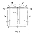
- FIG. 1 shows one preferred embodiment of the invention, which can be delineated as a double fiber bundle dialyzer.
- This apparatus is composed, in effect, of an outer casing that delimits two dialyzation chambers 2, 4 that may be disposed, effectively, side by side.
- Each dialyzation chamber 2, 4 is closed off by a respective part of the outer casing and manifolds 24, 26, 28, to be described below.
- Each dialyzation chamber contains a filter member in the form of a bundle 12, 14, respectively, of semi-permeable hollow membrane fibers.
- Each fiber has the form of a small diameter hollow tube.
- the outer casing parts have a common wall 20, the common wall being provided, near the bottom of the outer casing, with an opening forming a constricted passage for dialysate.
- Manifold 24 is provided with openings that place the upper ends of the fibers of bundle 12 in communication with a blood outlet compartment 30, while manifold 26 is provided with openings that place the upper ends of the fibers of bundle 14 in communication with a blood inlet compartment 34.
- Compartments 30 and 34 are delimited by header caps.
- Manifold 28 is provided with openings that place the lower ends of the fibers of bundles 12 and 14 in communication with an intermediate chamber 38 in which blood flows from the fibers of bundle 14 to the fibers of bundle 12 while blood from the various fibers become intermixed so that the blood entering the fibers of bundle 12 is of a more uniform composition.
- the component delimiting chamber 38 may be a further header cap.
- Manifolds 24, 26 and 28 close off the portions of each chamber 2, 4 through which dialysate flows so that dialysate cannot flow into chamber 38.
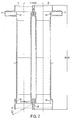
- Figure 2 is a cross-sectional view of one preferred embodiment of the outer casing of a dialyzer according to the present invention.
- This embodiment is composed essentially of two circularly cylindrical tubes delimiting the dialyzation chambers 2, 4.
- Common wall 20 with opening 22 is provided at the lower end of the outer casing.
- opening 22 may have a circular cross section with a diameter of the order of 1.4 mm and a longitudinal axis that has a length of the order of 6.6 mm and is inclined at an angle of the order of 60° - 85° to the longitudinal axis of each chamber 2, 4 and oriented to produce a flow having a direction with a component parallel to the direction of dialysate flow in chamber 4.
- the overall length of the outer casing may be of the order of 28.6 cm and the distance between the longitudinal axes of chambers 2 and 4 may be of the order of 5.2 cm.
- each chamber 2, 4 is of the order of 3.6 cm at the center of the chamber. However, other diameter values can be used. In general, the diameter of the chamber will be related to the size of the fiber bundle. As a rule of thumb, the total area of the fibers in a bundle, based on the outer diameters of all of the fiber OD in one plane, should preferably be approximately 50 - 55% of the cross-sectional area of the chamber in the same plane.
- manifolds 24, 26 and 28 are shown in broken lines in Figure 2 .
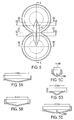
- Figure 3 shows an example of top header caps delimiting compartments 30 and 34.
- Figures 4 , 5 and 5A-5E show an example of the bottom header cap delimiting compartment 38.
- the bottom header cap is provided with a channel 60 designed to aid blood flow from fiber bundle 14 to fiber bundle 12.
- the dimensions of channel 60 are of the order of 10.5 mm wide and 5.3 mm high and the radius of curvature of channel 60 is also 5.3 mm.
- Channel 60 extends essentially between the midpoints of the two halves of the header cap. This provides a path for the blood to travel and mix while minimizing the pressure drop where chamber 38 narrows between fiber bundles.
- the top part is curved but the bottom forms a semicircle or "D shape" with the flat top of the manifold.
- the volumes enclosed by the fibers of bundles 12 and 14 define respective blood compartments in chambers 2 and 4, while the volumes surrounding the fibers of bundles 12 and 14 define respective dialysate compartments in chambers 2 and 4.
- Manifolds 24, 26 and 28 constitute walls that close off the upper ends of the dialysate compartments and manifold 28 constitutes a wall that close off the lower ends of the dialysate compartments.
- the lower end of common wall 20 bounds a constricted passage between the two dialysate compartments.
- Compartment 34 is provided with an inlet passage 40 for the delivery of blood into the apparatus, while compartment 30 has a blood outlet 42 for removal of blood from the apparatus.
- chamber 2 is provided with a dialysate inlet 44, while chamber 4 is provided with a dialysate outlet 46.
- fresh dialysate is introduced through inlet 44 into the dialysate compartment in chamber 2, flows through opening, or restricted passage, 22 near the bottom of common wall 20 into the dialysate compartment in chamber 4, and then out through outlet 46.
- blood that is to be dialyzed is introduced into chamber 34 via inlet 40, flows through the fibers of bundle 14 into intermediate chamber 38, and then flows through the fibers of bundle 12 to chamber 30 and finally exits the apparatus through outlet 42.
- plasma water is removed from blood flowing through the fibers of bundle 14 and is transferred into the dialysate compartment in chamber 4 by being filtered across the semipermeable membranes forming the walls of the fibers of bundle 14.
- intermediate chamber 38 Upon exiting the blood compartment in chamber 4, the blood enters and flows through intermediate chamber 38 and then into the blood compartment in chamber 2.
- the function of intermediate chamber 38 will be described below.
- HDF Hemodiafiltration
- Fresh dialysate fluid for this system may be generated using existing methods and standard dialysis equipment.
- the dialysate fluid enters the dialysate compartment in chamber 2 and flows in counter-current with respect to the blood flow.
- This dialysate fluid performs two functions: 1) it acts to set up a concentration gradient relative to the blood compartment, thereby inducing diffusion of solutes across the semi-permeable membranes from the blood compartment to the dialysate compartment in chamber 2; and 2) because of the relatively higher pressure of the incoming dialysate compared to the blood compartment pressure, it produces a backfiltration of dialysate into the blood compartment.
- the dialysate fluid Upon exiting chamber 2, the dialysate fluid enters the dialysate compartment in chamber 4, still flowing in counter-current with respect to the blood flow in the respective blood compartment.
- the dialysate flow rate increases as the dialysate flows through the dialysate compartment in chamber 4, due to filtration of plasma water from the blood compartment across the semi-permeable membranes of the fibers of bundle 14.
- Dialysate also flows around the fibers of each fiber bundle, entering at one side of the respective dialysate chamber and flowing diagonally across the chamber and around the membrane fibers before exiting at the other side, and the other end, of the respective chamber. This flow across, or around, both fiber bundles may enhance fiber surface contact and diffusive removal of substances.
- the spent or used dialysate Upon exiting the dialyzer, the spent or used dialysate is transported back to the dialysis machine and to the drain in a conventional manner.
- the fibers of both bundles may be of the same material and both bundles also have the purpose of diffusive removal of toxins. It is also possible, at high protein concentrations in the blood, that some backfiltration starts in fiber bundle 14.
- the volumetric control of a dialysis machine ensures proper ultrafiltration and controls the rates of filtration and backfiltration.
- the fiber bundle involved in the backfiltration, in chamber 2 acts as a final fluid quality filter and has been shown to bring both bacteria and endotoxin to levels that approach pharmaceutical grade fluids.
- the advantage of this system is that small molecules such as urea can be removed efficiently due to the appropriately large surface area of the two fiber bundles, and midsized molecules are removed efficiently due to the large filtration with backfiltration, which is optimized with this double fiber bundle configuration. No additional dialyzers, no final ultrafilters, no additional pumps or external equipment and no external substitution fluid are required.
- the dialyzer according to the invention can be given a large membrane surface area that will result in improved urea and creatinine removal.
- the novel technology on which the present invention is based makes possible a dialyzer having a membrane surface area of 3.0 m 2 or more.
- the double dialyzer configuration according to the present invention resolves the clotting issue as discussed herein, and also resolves the reverse ultrafiltration alarm problem by decreasing the dialysate out pressure due to the restricted passage between the dialysate compartments.
- the rate of ultrafiltration and midsize molecule removal will be greater in the dialyzer according to the invention than in prior art systems having the same dialyzer area and similar Kuf, Kuf being the coefficient of ultrafiltration for the filter member, i.e., the rate of plasma water fluid flux across the membrane, or fiber wall, per hour per mmHg of transmembrane pressure (TMP).
- TMP transmembrane pressure
- dialysate distribution and resultant clearance will be better in dialyzers according to the invention, at least when crimped fibers are used for the membranes. Specifically, crimped fibers result in a more uniform dialysate flow throughout the dialyzer. This results in improved clearance of small molecules. Also, the provision of two separate dialysate compartments communicating via the restricted passage, or orifice, will help to redistribute the dialysate flows so any channeling, even with straight fibers, will be all but eliminated in the second dialysate compartment.
- the system according to the present invention is constructed and operated to maintain the counter-current dialysate flow throughout both bundles whereas at least one existing dialyzer has a single chamber with counter-current flow in one stage that contains a filter bundle and concurrent flow, i.e., blood and dialysate flows in the same direction, in a second stage containing another bundle, which greatly reduces the diffusion gradient.
- a filter bundle and concurrent flow i.e., blood and dialysate flows in the same direction
- substitution fluid it is necessary to add substitution fluid directly into a space between the fiber bundles. If substitution fluid is not added, this dialyzer clots very quickly.
- the second stage will have a lower small molecule removal rate since the concentration gradient is smaller.
- substitution fluid requires a separate filter for the fluid generated on-line and a separate pump to control infusion, making the system more complicated and expensive to run than a dialyzer according to the invention.
- dialyzers according to the invention are intended to be connected to standard dialysis machines that are already in dialysis clinics to perform an HDF treatment.
- prior art machines require a specialized structure that has extra sensors to measure the amount of filtration, separate pumps to return the substitution fluid and extra filters since they reinfuse the substitution fluid either directly into the blood line or into the header of the dialyzer.
- these other systems will need to calculate the volume going into the system (blood and dialysate) and the volume coming out (blood and dialysate).
- the system needs to calculate the rates of filtration and then must add the proper amount of substitution fluid to the system to balance the fluid removed. So the equipment is complicated by balances or fluid control units that measure the fluid exchanged.
- the fluid balancing system can be a diaphragm pump such as in the Frensius machines or flow meter controlled system such as in the Gambro machines.
- An advantage of the present invention is that the double fiber bundle dialyzer can be used with any known dialysis machine with volumetric control to perform an HDF treatment without needing to set up additional infusion lines, filters and/or pumps or units.
- a dialyzer according to the invention can be used in existing dialysis machines without the need for additional hardware or modifications.
- a dialyzer according to the invention can be used with known dialysis machines, such as a standard Fresenius machine, on which a dialyzer according to the invention was tested, in place of a conventional dialyzer, using the exact same set-up as for a standard dialysis treatment, including standard blood lines.
- the dialyzer according to the invention will automatically enhance the filtration and back filtration based on its design. Nearly all current dialysis machines have a place for an ultrafilter. This is a filter that filters the dialysate fluid prior to reaching the dialyzer. It is a component of a dialysis machine, possibly not needed in systems according to the present invention.
- An ultrafilter is usually a hollow fiber filter similar to a standard dialyzer, but is designed to have the fluid diffuse across the fibers (filtration) and then flow to the dialyzer. All machines marketed within the past 5 years or more have a built in ultrafilter (also called an endotoxin filter).
- the double fiber bundle dialyzer according to the invention differs from the prior art (e.g., U.S. Pat. No. 5,700,372 ) in several ways.
- One important difference is that in the system according to the invention, blood passes through and exits the fibers of bundle 14, then enters a large space, i . e ., intermediate chamber 38, where the blood exiting all of the fibers of bundle 14 is mixed together before entering the fibers of bundle 12. No filtration, or back filtration, or substitution of fluid occurs in intermediate chamber 38; only blood flows through intermediate chamber 38.
- Chamber 38 performs an important function that serves to eliminate, or at least minimize, the adverse effects of a common problem in dialysis known as "channeling".
- Channeling can occur on the dialysate side or the blood side of the fibers. Channeling on the blood side is when blood flows through different fibers at different rates. In the fibers in which a relatively fast flow occurs, the fibers see more blood than do the fibers in which a slower blood flow occurs, although ultrafiltration occurs from all of the fibers. In the fibers experiencing slow blood flow, while plasma water is being removed by ultrafiltration (raising the hematocrit: the proportion of blood volume that is occupied by red blood cells), the blood will tend to clot and the fibers will become blocked.
- intermediate chamber space 38 in the double fiber bundle system acts to mix the blood while no filtration, or back filtration, or substitution of fluid is occurring so that the blood entering the fibers of bundle 12 is homogenous and at nearly the same pressure from one fiber to another.
- the pore size for toxin removal should be selected to produce as sharp a drop as possible in the elimination rate of molecules at 65,000 or 66,000 Daltons (the universal mass unit or atomic mass unit). Little or no molecular weight substances above 65,000 or 66,000 Daltons should be removed. This will minimize protein losses during treatment.
- membrane material of the fibers in bundles 12 and 14 would be a product marketed by Asahi Kasei Kuraray Medical Co., Ltd. under the trade names REXBRANE and Polysulfone APS, a polysulfone membrane with a hydrophilic gel layer.
- the fibers should be crimped to enhance dialysate flow. This crimping gives the fibers a form that follows a sinuous path along their length, which is the form of the REXBRANE fibers.
- Each fiber bundle may have a KuF (Coefficient of Ultrafiltration) of 20 - 26 ml/h/(mmHg TMP), TMP can be calculated as the average pressure on the blood side of the membrane minus the average pressure on the dialysate side of the membrane.
- KuF Coefficient of Ultrafiltration
- TMP is mostly determined by the hydrostatic pressure of the blood flow on the blood side of the membrane (favoring flux from the blood side to the dialysate side), the opposite pressure of the dialysate fluid on the dialysate side of the membrane (favoring dialysate fluid flux to the blood side) as well as the opposite pressure associated with the oncotic pressures (which is a form of osmotic pressure exerted by proteins in blood plasma that normally tends to pull water into the circulatory system) of the blood proteins (favoring fluid flux from the dialysate side to the blood side).
- the oncotic pressures increase as the protein concentration increases due to less plasma water and a relatively higher protein concentration.
- the pressure drop between the inlet and outlet of the dialysate compartment in chamber 2 is slight due to the presence of the constricted passage between the dialysate compartments.
- the pressure drop across the constricted passage is lower with a 500 ml/min flow rate since the flow is lower. This yields a higher average pressure in the dialysate compartment of chamber 4 for a 500 ml/min dialysate flow than for an 800 ml/min flow.
- the higher pressure on the dialysate side of chamber 4 yields a drop in TMP.
- the conventional volumetric controller (not shown) of the dialysis machine to which the dialyzer is connected which makes sure that the dialysate volume entering via inlet 44 is the same as the volume that leaves via outlet 46, can apply a slight negative pressure at outlet 46, thereby pulling fluid from the blood side to make the incoming and outgoing volumes the same.
- Additional fluid removal is normally programmed into the dialysis machine in order to remove the excess fluid a patient consumes between treatments. This excess fluid removal is controlled by a separate pump in all dialysis machines and works in conjunction with the present invention.
- the Kuf coefficient of ultrafiltration
- the Kuf is calculated for the fibers of bundle 14 only using human blood reconstituted with saline and bovine albumin at a concentration of ⁇ 6g/dL (this also effects the measured Kuf. If it was measured with saline, the Kuf would be calculated to be much higher due to the lower viscosity and lack of blood proteins, i.e. albumin).
- the total dialysate pressure drop between inlet 44 and outlet 46 should be about 170 mmHg. There is some variability dependent on blood flow, rate of filtration with backfiltration and access needle size used or catheter type (which effects venous pressure of returning blood at outlet 42).
- the pressure drop in Chamber 2 will vary dependent on blood flow, a higher blood flow resulting in a higher pressure drop.
- a pressure drop of 75% at blood flows of 550 ml/min and a pressure drop of 62% at blood flows of 350 ml/min were measured.
- the double dialyzer according to the invention has two separate bundles of fibers for filtration, with fiber bundle headers at the ends of the chambers.
- Manifolds 24, 26 and 28 may be constituted by potting compound bodies.
- the fibers enter and exit through these bodies so that the blood encounters some resistance upon entering the fibers and the resistance at the entry to each fiber bundle aids filtration.
- the potting compound is used to separate the internal pathways presented by the fibers from the dialysate compartments. This is done by inserting the fiber bundles into the dialyzer casing. Thus, a lower end header cap will be provided.
- the potting compound bodies are formed in place before the top and bottom header caps are put in place.
- a special cap is clamped on each end of the casing and potting compound (polyurethane material) is injected into the special caps and around the fibers.
- the chambers are usually spun in order to distribute the potting compound so as to reliably form seals between the dialysate side and blood side of each chamber.
- potting compound seals will be formed around the fiber ends that will extend into chamber 38, as well as around the fiber ends that will extend into compartments 30 and 34, after which the fiber bundle ends projecting from the potting compound bodies may be sliced off.
- the header caps may then be assembled to the ends of the casing.
- Two separate dialysate compartments are provided in order to be able to provide the flow constriction 22 therebetween to control the rates of filtration and backfiltration.
- the flow constriction between dialysate compartments, near the bottom of wall 20, is a key component of the double dialyzer according to the invention. If the flow constriction yields too low of a pressure drop, the machine will alarm for low TMP because the average dialysate pressure will be too low for the amount of filtration the system produces.
- the dialyzer could clot as the TMP of fiber bundle 14 in chamber 4 increases (because of very low dialysate pressures), causing additional ultrafiltration of plasma water and hemoconcentrating the blood in chamber 4.
- the membrane fibers can have a smaller ID, and/or thinner walls, and/or smaller or larger fiber membrane surface areas (e.g., 0.9 to 1.8 m 2 for each bundle). It is possible to have a difference in area between the two fiber bundles. This could be, for example 1.3 m 2 for bundle 12 and 1.5 m2 for bundle 14, although this may make manufacturing more difficult.
- Unequal surface areas may also have to be balanced by possibly changing the filtration capability of the fiber bundles. If a fiber bundle having a smaller surface area were provided in one chamber, this may need to be compensated with a higher filtration capability in order to provide the correct filtration and backfiltration. If the inner diameter of each fiber were made smaller, the result would be an increase in pressure drop and an increase in filtration. There are numerous possible configurations.
- the constricted passage 22 in wall 20 is important because if there were no constriction, the pressure at dialysate outlet 46 would be substantially equal to the pressure at dialysate inlet 44, so that there would be less filtration with backfiltration. Therefore, clearance of middle weight toxins would be reduced and there would also be problems with the dialysis machine because the dialysate pressure at outlet 46 would be higher than if the constricted passage was present. This higher pressure at outlet 46 will result in a reverse TMP alarm.
- a double fiber bundle with similar parameters but smaller total membrane surface areas can be used to provide a hemodiafiltration treatment at lower blood flows (200 ml/min) and lower dialysate flows (100 - 500 ml/min).
- the constricted passage between dialysate compartments will still be required in order to drop the average of the dialysate side pressures to allow the double fiber bundle dialyzer system to run on standard equipment.
- Distribution rings or dialysate diverters, commonly used in this art, may also be provided near the inlet and outlet of dialysate ports 44 and 46, below manifolds 24 and 26, and at the bottom of the chambers, above manifold 28, to aid in distribution of the dialysate around the fibers. Examples of such diverters are disclosed in U.S. Pat. Nos. 4,396,510 ; 5,084,244 ; and 6, 623, 638 .
- the casing shown in Figure 2 is provided with diverters 52, 53, 54 and 55, which may be integral parts of the casing.
- Dialysate entering via inlet 44 flows around diverter 52 and upwardly over the upper edge of diverter 52 before entering the dialysate compartment in chamber 2.
- dialysate exiting from passage 22 will flow around diverter 55 and then under the lower edge of diverter 55 before entering the dialysate compartment in chamber 4.
- Diverters 53 and 54 are also used to aid in dialysate flow distribution by forcing the fluid to flow from the center of the dialyzer over the diverter to the periphery where dialysate will flow through restricted passage via diverter 53 and to port 46 via diverter 54. Since channeling commonly occurs along the walls of the chambers, the diverters force the dialysate away from the walls to the center where the fibers are located.
- This present invention may also be used with the specialized dialysis machines capable of delivering HDF treatments.
- the use of pre-dilution HDF (fluid infused before entering the dialyzer) using the present invention as the dialyzer will deliver a rate of filtration equal to or greater than the amount of filtration of which a standard HDF dialyzer in the same pre-dilution modality is capable.
Landscapes
- Health & Medical Sciences (AREA)
- Heart & Thoracic Surgery (AREA)
- Urology & Nephrology (AREA)
- Animal Behavior & Ethology (AREA)
- Hematology (AREA)
- Veterinary Medicine (AREA)
- Vascular Medicine (AREA)
- Engineering & Computer Science (AREA)
- Anesthesiology (AREA)
- Biomedical Technology (AREA)
- Public Health (AREA)
- Life Sciences & Earth Sciences (AREA)
- General Health & Medical Sciences (AREA)
- Emergency Medicine (AREA)
- Chemical & Material Sciences (AREA)
- Chemical Kinetics & Catalysis (AREA)
- External Artificial Organs (AREA)
Claims (16)
- Dialyseur comprenant :des première et deuxième chambres de dialyse (2, 4), et une chambre intermédiaire (38) interposée entre lesdites première et deuxième chambres de dialyse (2, 4), où,chacune desdites chambres de dialyse (2, 4) a des première et deuxième extrémités opposées ;chacune desdites chambres de dialyse contient un élément de filtre qui sépare ladite chambre en un compartiment de sang (12, 14) et un compartiment de dialysat, chacun desdits compartiments s'étendant entre lesdites première et deuxième extrémités ;ledit élément de filtre dans ladite première chambre est réalisé en un matériau filtrant pour filtrer l'eau plasmatique à partir du sang ;ledit élément de filtre dans ladite deuxième chambre est réalisé en un matériau filtrant pour le passage du dialysat dudit compartiment de dialysat audit compartiment de sang (12, 14) ;ladite première chambre (4) a, au niveau de ladite première extrémité de celle-ci, une entrée de sang (40) communiquant avec ledit compartiment de sang et une sortie de dialysat (46) communiquant avec ledit compartiment de dialysat ;ladite deuxième chambre (2) a, au niveau de ladite première extrémité de celle-ci, une sortie de sang (42) communiquant avec ledit compartiment de sang et une entrée de dialysat (44) communiquant avec ledit compartiment de dialysat ;ladite chambre intermédiaire (38) s'étend entre ladite deuxième extrémité de ladite première chambre de dialyse (4) et ladite deuxième extrémité de ladite deuxième chambre de dialyse (2) et communique uniquement avec lesdits compartiments de sang (12, 14) ;lesdites entrées et sorties de sang et de dialysat (40, 42, 44, 46) sont positionnées pour produire des écoulements de dialysat à contre-courant par rapport à des écoulements de sang dans lesdites deux chambres ; etlesdites première et deuxième chambres (2, 4) sont construites pour fournir un trajet d'écoulement de dialysat entre lesdits compartiments de dialysat au niveau desdites deuxièmes extrémités desdites chambrescaractérisé en ce que ledit trajet d'écoulement de dialysat fournit un passage à étranglement (22) entre lesdits compartiments de dialysat, où ledit passage à étranglement (22) est orienté pour fournir un trajet d'écoulement qui forme un angle aigu avec la direction d'écoulement de sang dans chacun desdits compartiments de sang (12, 14).
- Dialyseur de la revendication 1, dans lequel lesdites première et deuxième chambres (2, 4) sont séparées par une paroi commune (20) ayant une ouverture (22) qui constitue ledit trajet d'écoulement de dialysat et qui fournit ledit passage à étranglement (22) entre lesdits compartiments de dialysat.
- Dialyseur de la revendication 2, dans lequel ladite paroi commune (20) a une partie positionnée entre ladite ouverture et lesdites deuxièmes extrémités desdites chambres de dialyse.
- Dialyseur de la revendication 3, dans lequel chacun desdits éléments de filtre comprend un faisceau de fibres creuses du matériau filtrant respectif.
- Dialyseur de la revendication 4, comprenant en outre un premier déflecteur d'écoulement disposé dans ledit compartiment de dialysat dans ladite deuxième chambre (2) au niveau de ladite entrée de dialysat pour distribuer le dialysat autour desdites fibres creuses dans ladite deuxième chambre (2).
- Dialyseur de la revendication 5, comprenant en outre un deuxième déflecteur d'écoulement disposé dans ledit compartiment de dialysat dans ladite première chambre (4) au niveau dudit trajet d'écoulement de dialysat pour distribuer le dialysat autour desdites fibres creuses dans ladite première chambre (4).
- Dialyseur de la revendication 1, dans lequel chacun desdits éléments de filtre comprend un faisceau de fibres creuses du matériau filtrant respectif.
- Dialyseur de la revendication 7, comprenant en outre un premier déflecteur d'écoulement disposé dans ledit compartiment de dialysat dans ladite deuxième chambre (2) au niveau de ladite entrée de dialysat pour distribuer le dialysat autour desdites fibres creuses dans ladite deuxième chambre (2).
- Dialyseur de la revendication 8, comprenant en outre un deuxième déflecteur d'écoulement disposé dans ledit compartiment de dialysat dans ladite première chambre (4) au niveau dudit trajet d'écoulement de dialysat pour distribuer le dialysat autour desdites fibres creuses dans ladite première chambre (4).
- Dialyseur de la revendication 1, dans lequel ledit passage à étranglement (22) a un diamètre de l'ordre de 1,0 mm à 1,6 mm.
- Dialyseur de la revendication 10, dans lequel ledit passage à étranglement (22) a une section transversale circulaire.
- Dialyseur de la revendication 11, dans lequel l'angle aigu a une valeur de l'ordre de 60' à 85'.
- Dialyseur de la revendication 1, dans lequel ledit trajet d'écoulement de dialysat est dimensionné pour produire une chute de pression de dialysat de 50 mmHg à un débit de dialysat de 500 ml/min.
- Dialyseur de la revendication 1, dans lequel ledit trajet d'écoulement de dialysat est dimensionné pour produire une chute de pression de dialysat d'environ 100 mmHg à un débit de dialysat de 800 ml/min.
- Dialyseur de la revendication 1, dans lequel le passage à étranglement (22) est conçu pour produire une chute de pression de dialysat entre ladite deuxième chambre de dialyse (2) et ladite première chambre de dialyse (4), et, pour effectuer une dialyse, les seules connexions audit dialyseur étant constituées de ladite entrée de sang (40), de ladite sortie de sang (42), de ladite entrée de dialysat (44) et de ladite sortie de dialysat (46).
- Dialyseur de la revendication 1, dans lequel, ledit passage à étranglement (22) est dimensionné de sorte que, lors du fonctionnement dudit dialyseur, la chute de pression de dialysat entre ladite deuxième chambre de dialyse et ladite première chambre de dialyse provoque l'élimination de l'eau plasmatique du sang dans ledit compartiment de sang de ladite première chambre de dialyse (4) et provoque la filtration du dialysat à partir dudit compartiment de dialysat dans ledit compartiment de sang de ladite deuxième chambre de dialyse (2).
Applications Claiming Priority (2)
| Application Number | Priority Date | Filing Date | Title |
|---|---|---|---|
| US8076908P | 2008-07-15 | 2008-07-15 | |
| PCT/US2009/050494 WO2010009095A2 (fr) | 2008-07-15 | 2009-07-14 | Dialyseur à double faisceau de fibres |
Publications (3)
| Publication Number | Publication Date |
|---|---|
| EP2313125A2 EP2313125A2 (fr) | 2011-04-27 |
| EP2313125A4 EP2313125A4 (fr) | 2015-01-21 |
| EP2313125B1 true EP2313125B1 (fr) | 2016-04-06 |
Family
ID=41550984
Family Applications (1)
| Application Number | Title | Priority Date | Filing Date |
|---|---|---|---|
| EP09798633.5A Active EP2313125B1 (fr) | 2008-07-15 | 2009-07-14 | Dialyseur à double faisceau de fibres |
Country Status (5)
| Country | Link |
|---|---|
| US (2) | US8883008B2 (fr) |
| EP (1) | EP2313125B1 (fr) |
| JP (1) | JP5216916B2 (fr) |
| BR (1) | BRPI0916763B8 (fr) |
| WO (1) | WO2010009095A2 (fr) |
Families Citing this family (20)
| Publication number | Priority date | Publication date | Assignee | Title |
|---|---|---|---|---|
| DE102011110472A1 (de) * | 2011-07-29 | 2013-01-31 | Fresenius Medical Care Deutschland Gmbh | Verfahren sowie Vorrichtungen zum Ablösen von Gasansammlungen von einem Gerinnselfänger eines extrakorporalen Blutkreislaufs |
| ES2757557T3 (es) | 2011-12-29 | 2020-04-29 | Delcath Systems Inc | Filtro y aparato de bastidor y método de uso |
| EP2800592B1 (fr) * | 2012-01-04 | 2019-03-06 | Medtronic Inc. | Système de filtration à étages multiples pour l'élimination d'un fluide du sang |
| US10010663B2 (en) | 2013-02-01 | 2018-07-03 | Medtronic, Inc. | Fluid circuit for delivery of renal replacement therapies |
| US10850016B2 (en) | 2013-02-01 | 2020-12-01 | Medtronic, Inc. | Modular fluid therapy system having jumpered flow paths and systems and methods for cleaning and disinfection |
| US9623164B2 (en) | 2013-02-01 | 2017-04-18 | Medtronic, Inc. | Systems and methods for multifunctional volumetric fluid control |
| US9144640B2 (en) | 2013-02-02 | 2015-09-29 | Medtronic, Inc. | Sorbent cartridge configurations for improved dialysate regeneration |
| US9827361B2 (en) | 2013-02-02 | 2017-11-28 | Medtronic, Inc. | pH buffer measurement system for hemodialysis systems |
| WO2015153370A2 (fr) | 2014-03-29 | 2015-10-08 | Labib Mohamed E | Cartouches et systèmes de traitement du sang, et procédés pour des thérapies sanguines extracorporelles |
| US9713665B2 (en) | 2014-12-10 | 2017-07-25 | Medtronic, Inc. | Degassing system for dialysis |
| US10098993B2 (en) | 2014-12-10 | 2018-10-16 | Medtronic, Inc. | Sensing and storage system for fluid balance |
| US10874787B2 (en) | 2014-12-10 | 2020-12-29 | Medtronic, Inc. | Degassing system for dialysis |
| WO2016130128A1 (fr) * | 2015-02-12 | 2016-08-18 | Mirimedical Llc | Dialyseur à double faisceau de fibres amélioré |
| US10426884B2 (en) | 2015-06-26 | 2019-10-01 | Novaflux Inc. | Cartridges and systems for outside-in flow in membrane-based therapies |
| WO2017053805A1 (fr) | 2015-09-24 | 2017-03-30 | Labib Mohamed E | Cartouches pour thérapies basées sur une membrane de fibres creuses |
| US11278654B2 (en) | 2017-12-07 | 2022-03-22 | Medtronic, Inc. | Pneumatic manifold for a dialysis system |
| US11033667B2 (en) | 2018-02-02 | 2021-06-15 | Medtronic, Inc. | Sorbent manifold for a dialysis system |
| US11110215B2 (en) | 2018-02-23 | 2021-09-07 | Medtronic, Inc. | Degasser and vent manifolds for dialysis |
| DE102018008459A1 (de) | 2018-10-29 | 2020-04-30 | Enmodes Gmbh | Vorrichtung für den Stoffaustausch zwischen Blut- und wenigstens einem Gas/Gasgemisch |
| US10926019B2 (en) | 2019-06-05 | 2021-02-23 | Choon Kee Lee | Gradient dialysate hemodiafiltration |
Family Cites Families (24)
| Publication number | Priority date | Publication date | Assignee | Title |
|---|---|---|---|---|
| US4289623A (en) * | 1975-11-05 | 1981-09-15 | Extracorporeal Medical Specialties, Inc. | Hollow fiber dialysis |
| SE7611942L (sv) * | 1975-11-05 | 1977-05-06 | Extracorporeal Med Spec | Dialysator med ihaliga fibrer |
| US4227295A (en) * | 1978-07-27 | 1980-10-14 | Baxter Travenol Laboratories, Inc. | Method of potting the ends of a bundle of hollow fibers positioned in a casing |
| DE2851929A1 (de) * | 1978-12-01 | 1980-06-04 | Peter Weiss | Dialysator fuer kuenstliche nieren |
| US4396510A (en) * | 1981-01-08 | 1983-08-02 | Bio-Med Corporation | Mass transfer device |
| US4707268A (en) * | 1982-10-18 | 1987-11-17 | Baxter Travenol Laboratories, Inc. | Hollow fiber potted microfilter |
| JPS61276563A (ja) | 1985-04-24 | 1986-12-06 | バイオ・ライン・サプライズ・リミテツド | 二つのボデイの透析器 |
| DE8512777U1 (de) * | 1985-04-30 | 1985-06-20 | Bio Line Supplies Ltd., St. Helier | Zweitteilige Dialysiervorrichtung |
| JPH0614965B2 (ja) * | 1989-01-10 | 1994-03-02 | テルモ株式会社 | 人工肺 |
| EP0701826B1 (fr) * | 1994-09-02 | 2000-03-22 | Terumo Kabushiki Kaisha | Appareil de dialyse |
| JPH09276401A (ja) | 1996-04-15 | 1997-10-28 | Nitto Denko Corp | 血液透析用膜モジュ−ル |
| US5899980A (en) * | 1997-08-11 | 1999-05-04 | Trivnet Ltd. | Retail method over a wide area network |
| US6406631B1 (en) * | 1999-07-30 | 2002-06-18 | Nephros, Inc. | Two stage diafiltration method and apparatus |
| US6315895B1 (en) * | 1999-12-30 | 2001-11-13 | Nephros, Inc. | Dual-stage hemodiafiltration cartridge |
| KR100604460B1 (ko) * | 2000-12-11 | 2006-07-26 | 니프로스, 인코포레이티드 | 혈액 투석여과/혈액 여과 카트리지 |
| US6623638B2 (en) * | 2001-06-01 | 2003-09-23 | Baxter International Inc. | Hemodialyzer having improved dialysate perfusion |
| US6702561B2 (en) * | 2001-07-12 | 2004-03-09 | Nxstage Medical, Inc. | Devices for potting a filter for blood processing |
| US6843779B1 (en) * | 2001-09-17 | 2005-01-18 | Mirimedical, Llc | Hemodialysis system |
| JP4173969B2 (ja) * | 2002-03-14 | 2008-10-29 | 旭化成クラレメディカル株式会社 | 血液透析ろ過器及び血液透析ろ過装置 |
| EP1444998A1 (fr) * | 2003-02-05 | 2004-08-11 | B. Braun Medizintechnologie GmbH | Appareil de traitement pour liquide biologique |
| EP1466657B1 (fr) * | 2003-04-11 | 2012-10-03 | Gambro Lundia AB | Dispositif de filtration avec plus d'une chambre à filtration |
| JP4328902B2 (ja) | 2003-10-14 | 2009-09-09 | 鐘一 金 | オンライン型大量液置換型血液透析器 |
| US7874998B2 (en) * | 2005-11-04 | 2011-01-25 | The Regents Of The University Of Michigan | Filtration devices and related methods thereof |
| KR20090118536A (ko) * | 2008-05-14 | 2009-11-18 | 탑엠앤에이 주식회사 | 혈액 투석장치 |
-
2009
- 2009-07-14 BR BRPI0916763A patent/BRPI0916763B8/pt not_active IP Right Cessation
- 2009-07-14 EP EP09798633.5A patent/EP2313125B1/fr active Active
- 2009-07-14 WO PCT/US2009/050494 patent/WO2010009095A2/fr active Application Filing
- 2009-07-14 JP JP2011518832A patent/JP5216916B2/ja active Active
- 2009-07-14 US US13/054,306 patent/US8883008B2/en active Active
-
2014
- 2014-02-12 US US14/178,861 patent/US20140158605A1/en not_active Abandoned
Also Published As
| Publication number | Publication date |
|---|---|
| EP2313125A2 (fr) | 2011-04-27 |
| US8883008B2 (en) | 2014-11-11 |
| WO2010009095A3 (fr) | 2010-03-18 |
| BRPI0916763B8 (pt) | 2021-06-22 |
| WO2010009095A2 (fr) | 2010-01-21 |
| US20110120930A1 (en) | 2011-05-26 |
| BRPI0916763B1 (pt) | 2020-01-14 |
| JP5216916B2 (ja) | 2013-06-19 |
| US20140158605A1 (en) | 2014-06-12 |
| EP2313125A4 (fr) | 2015-01-21 |
| BRPI0916763A2 (pt) | 2018-02-14 |
| JP2011528268A (ja) | 2011-11-17 |
Similar Documents
| Publication | Publication Date | Title |
|---|---|---|
| EP2313125B1 (fr) | Dialyseur à double faisceau de fibres | |
| KR100649260B1 (ko) | 이중-스테이지 여과 카트리지 | |
| KR100604460B1 (ko) | 혈액 투석여과/혈액 여과 카트리지 | |
| CN101035576B (zh) | 聚砜血液透析器 | |
| JP4571621B2 (ja) | 溶質の選択的抽出による血液の体外処理のための装置及び方法 | |
| JP2003518996A (ja) | 二段式血液透析濾過カートリッジ | |
| US20070119781A1 (en) | Apparatus and method for enhanced hemodialysis performance | |
| US5942112A (en) | Hollow fiber ultradialyzer apparatus | |
| US10744251B2 (en) | Double fiber bundle dialyzer | |
| Ronco et al. | New developments in hemodialyzers | |
| US20180280884A1 (en) | Filter device, system and method for filtration of fluids | |
| Ronco | What clinically important advances in understanding and improving dialyzer function have occurred recently? | |
| Lee et al. | Convection‐enhanced high‐flux hemodialysis | |
| Vienken et al. | New developments in hemodialyzers | |
| Fiore et al. | Internal hemodiafiltration (iHDF): a possible option to expand hemodiafiltration therapy | |
| US11179678B2 (en) | System and method for filtration and/or dilution of fluids | |
| KR100929147B1 (ko) | 환류가 향상된 혈액투석기 | |
| Atasoyu et al. | Which One is More Effective: Ethylene Vinyl Alcohol (EVAL) or Polysul-phone Dialyzer? |
Legal Events
| Date | Code | Title | Description |
|---|---|---|---|
| PUAI | Public reference made under article 153(3) epc to a published international application that has entered the european phase |
Free format text: ORIGINAL CODE: 0009012 |
|
| 17P | Request for examination filed |
Effective date: 20110211 |
|
| AK | Designated contracting states |
Kind code of ref document: A2 Designated state(s): AT BE BG CH CY CZ DE DK EE ES FI FR GB GR HR HU IE IS IT LI LT LU LV MC MK MT NL NO PL PT RO SE SI SK SM TR |
|
| AX | Request for extension of the european patent |
Extension state: AL BA RS |
|
| DAX | Request for extension of the european patent (deleted) | ||
| A4 | Supplementary search report drawn up and despatched |
Effective date: 20141218 |
|
| GRAP | Despatch of communication of intention to grant a patent |
Free format text: ORIGINAL CODE: EPIDOSNIGR1 |
|
| INTG | Intention to grant announced |
Effective date: 20151026 |
|
| GRAS | Grant fee paid |
Free format text: ORIGINAL CODE: EPIDOSNIGR3 |
|
| GRAA | (expected) grant |
Free format text: ORIGINAL CODE: 0009210 |
|
| AK | Designated contracting states |
Kind code of ref document: B1 Designated state(s): AT BE BG CH CY CZ DE DK EE ES FI FR GB GR HR HU IE IS IT LI LT LU LV MC MK MT NL NO PL PT RO SE SI SK SM TR |
|
| REG | Reference to a national code |
Ref country code: GB Ref legal event code: FG4D |
|
| REG | Reference to a national code |
Ref country code: AT Ref legal event code: REF Ref document number: 787029 Country of ref document: AT Kind code of ref document: T Effective date: 20160415 Ref country code: CH Ref legal event code: EP |
|
| REG | Reference to a national code |
Ref country code: IE Ref legal event code: FG4D |
|
| REG | Reference to a national code |
Ref country code: DE Ref legal event code: R096 Ref document number: 602009037559 Country of ref document: DE |
|
| REG | Reference to a national code |
Ref country code: FR Ref legal event code: PLFP Year of fee payment: 8 |
|
| REG | Reference to a national code |
Ref country code: LT Ref legal event code: MG4D Ref country code: NL Ref legal event code: MP Effective date: 20160406 |
|
| REG | Reference to a national code |
Ref country code: AT Ref legal event code: MK05 Ref document number: 787029 Country of ref document: AT Kind code of ref document: T Effective date: 20160406 |
|
| PG25 | Lapsed in a contracting state [announced via postgrant information from national office to epo] |
Ref country code: NL Free format text: LAPSE BECAUSE OF FAILURE TO SUBMIT A TRANSLATION OF THE DESCRIPTION OR TO PAY THE FEE WITHIN THE PRESCRIBED TIME-LIMIT Effective date: 20160406 |
|
| PG25 | Lapsed in a contracting state [announced via postgrant information from national office to epo] |
Ref country code: LT Free format text: LAPSE BECAUSE OF FAILURE TO SUBMIT A TRANSLATION OF THE DESCRIPTION OR TO PAY THE FEE WITHIN THE PRESCRIBED TIME-LIMIT Effective date: 20160406 Ref country code: PL Free format text: LAPSE BECAUSE OF FAILURE TO SUBMIT A TRANSLATION OF THE DESCRIPTION OR TO PAY THE FEE WITHIN THE PRESCRIBED TIME-LIMIT Effective date: 20160406 Ref country code: IS Free format text: LAPSE BECAUSE OF FAILURE TO SUBMIT A TRANSLATION OF THE DESCRIPTION OR TO PAY THE FEE WITHIN THE PRESCRIBED TIME-LIMIT Effective date: 20160806 Ref country code: NO Free format text: LAPSE BECAUSE OF FAILURE TO SUBMIT A TRANSLATION OF THE DESCRIPTION OR TO PAY THE FEE WITHIN THE PRESCRIBED TIME-LIMIT Effective date: 20160706 Ref country code: FI Free format text: LAPSE BECAUSE OF FAILURE TO SUBMIT A TRANSLATION OF THE DESCRIPTION OR TO PAY THE FEE WITHIN THE PRESCRIBED TIME-LIMIT Effective date: 20160406 |
|
| PG25 | Lapsed in a contracting state [announced via postgrant information from national office to epo] |
Ref country code: ES Free format text: LAPSE BECAUSE OF FAILURE TO SUBMIT A TRANSLATION OF THE DESCRIPTION OR TO PAY THE FEE WITHIN THE PRESCRIBED TIME-LIMIT Effective date: 20160406 Ref country code: HR Free format text: LAPSE BECAUSE OF FAILURE TO SUBMIT A TRANSLATION OF THE DESCRIPTION OR TO PAY THE FEE WITHIN THE PRESCRIBED TIME-LIMIT Effective date: 20160406 Ref country code: AT Free format text: LAPSE BECAUSE OF FAILURE TO SUBMIT A TRANSLATION OF THE DESCRIPTION OR TO PAY THE FEE WITHIN THE PRESCRIBED TIME-LIMIT Effective date: 20160406 Ref country code: SE Free format text: LAPSE BECAUSE OF FAILURE TO SUBMIT A TRANSLATION OF THE DESCRIPTION OR TO PAY THE FEE WITHIN THE PRESCRIBED TIME-LIMIT Effective date: 20160406 Ref country code: GR Free format text: LAPSE BECAUSE OF FAILURE TO SUBMIT A TRANSLATION OF THE DESCRIPTION OR TO PAY THE FEE WITHIN THE PRESCRIBED TIME-LIMIT Effective date: 20160707 Ref country code: PT Free format text: LAPSE BECAUSE OF FAILURE TO SUBMIT A TRANSLATION OF THE DESCRIPTION OR TO PAY THE FEE WITHIN THE PRESCRIBED TIME-LIMIT Effective date: 20160808 Ref country code: LV Free format text: LAPSE BECAUSE OF FAILURE TO SUBMIT A TRANSLATION OF THE DESCRIPTION OR TO PAY THE FEE WITHIN THE PRESCRIBED TIME-LIMIT Effective date: 20160406 |
|
| PG25 | Lapsed in a contracting state [announced via postgrant information from national office to epo] |
Ref country code: BE Free format text: LAPSE BECAUSE OF FAILURE TO SUBMIT A TRANSLATION OF THE DESCRIPTION OR TO PAY THE FEE WITHIN THE PRESCRIBED TIME-LIMIT Effective date: 20160406 |
|
| REG | Reference to a national code |
Ref country code: DE Ref legal event code: R097 Ref document number: 602009037559 Country of ref document: DE |
|
| PG25 | Lapsed in a contracting state [announced via postgrant information from national office to epo] |
Ref country code: DK Free format text: LAPSE BECAUSE OF FAILURE TO SUBMIT A TRANSLATION OF THE DESCRIPTION OR TO PAY THE FEE WITHIN THE PRESCRIBED TIME-LIMIT Effective date: 20160406 Ref country code: CZ Free format text: LAPSE BECAUSE OF FAILURE TO SUBMIT A TRANSLATION OF THE DESCRIPTION OR TO PAY THE FEE WITHIN THE PRESCRIBED TIME-LIMIT Effective date: 20160406 Ref country code: EE Free format text: LAPSE BECAUSE OF FAILURE TO SUBMIT A TRANSLATION OF THE DESCRIPTION OR TO PAY THE FEE WITHIN THE PRESCRIBED TIME-LIMIT Effective date: 20160406 Ref country code: SK Free format text: LAPSE BECAUSE OF FAILURE TO SUBMIT A TRANSLATION OF THE DESCRIPTION OR TO PAY THE FEE WITHIN THE PRESCRIBED TIME-LIMIT Effective date: 20160406 Ref country code: RO Free format text: LAPSE BECAUSE OF FAILURE TO SUBMIT A TRANSLATION OF THE DESCRIPTION OR TO PAY THE FEE WITHIN THE PRESCRIBED TIME-LIMIT Effective date: 20160406 |
|
| PLBE | No opposition filed within time limit |
Free format text: ORIGINAL CODE: 0009261 |
|
| STAA | Information on the status of an ep patent application or granted ep patent |
Free format text: STATUS: NO OPPOSITION FILED WITHIN TIME LIMIT |
|
| PG25 | Lapsed in a contracting state [announced via postgrant information from national office to epo] |
Ref country code: SM Free format text: LAPSE BECAUSE OF FAILURE TO SUBMIT A TRANSLATION OF THE DESCRIPTION OR TO PAY THE FEE WITHIN THE PRESCRIBED TIME-LIMIT Effective date: 20160406 |
|
| REG | Reference to a national code |
Ref country code: CH Ref legal event code: PL |
|
| 26N | No opposition filed |
Effective date: 20170110 |
|
| GBPC | Gb: european patent ceased through non-payment of renewal fee |
Effective date: 20160714 |
|
| PG25 | Lapsed in a contracting state [announced via postgrant information from national office to epo] |
Ref country code: MC Free format text: LAPSE BECAUSE OF FAILURE TO SUBMIT A TRANSLATION OF THE DESCRIPTION OR TO PAY THE FEE WITHIN THE PRESCRIBED TIME-LIMIT Effective date: 20160406 |
|
| PG25 | Lapsed in a contracting state [announced via postgrant information from national office to epo] |
Ref country code: LI Free format text: LAPSE BECAUSE OF NON-PAYMENT OF DUE FEES Effective date: 20160731 Ref country code: CH Free format text: LAPSE BECAUSE OF NON-PAYMENT OF DUE FEES Effective date: 20160731 |
|
| REG | Reference to a national code |
Ref country code: IE Ref legal event code: MM4A |
|
| PG25 | Lapsed in a contracting state [announced via postgrant information from national office to epo] |
Ref country code: GB Free format text: LAPSE BECAUSE OF NON-PAYMENT OF DUE FEES Effective date: 20160714 Ref country code: SI Free format text: LAPSE BECAUSE OF FAILURE TO SUBMIT A TRANSLATION OF THE DESCRIPTION OR TO PAY THE FEE WITHIN THE PRESCRIBED TIME-LIMIT Effective date: 20160406 |
|
| REG | Reference to a national code |
Ref country code: FR Ref legal event code: PLFP Year of fee payment: 9 |
|
| PG25 | Lapsed in a contracting state [announced via postgrant information from national office to epo] |
Ref country code: IE Free format text: LAPSE BECAUSE OF NON-PAYMENT OF DUE FEES Effective date: 20160714 |
|
| PG25 | Lapsed in a contracting state [announced via postgrant information from national office to epo] |
Ref country code: LU Free format text: LAPSE BECAUSE OF NON-PAYMENT OF DUE FEES Effective date: 20160714 |
|
| PG25 | Lapsed in a contracting state [announced via postgrant information from national office to epo] |
Ref country code: CY Free format text: LAPSE BECAUSE OF FAILURE TO SUBMIT A TRANSLATION OF THE DESCRIPTION OR TO PAY THE FEE WITHIN THE PRESCRIBED TIME-LIMIT Effective date: 20160406 Ref country code: HU Free format text: LAPSE BECAUSE OF FAILURE TO SUBMIT A TRANSLATION OF THE DESCRIPTION OR TO PAY THE FEE WITHIN THE PRESCRIBED TIME-LIMIT; INVALID AB INITIO Effective date: 20090714 |
|
| PG25 | Lapsed in a contracting state [announced via postgrant information from national office to epo] |
Ref country code: TR Free format text: LAPSE BECAUSE OF FAILURE TO SUBMIT A TRANSLATION OF THE DESCRIPTION OR TO PAY THE FEE WITHIN THE PRESCRIBED TIME-LIMIT Effective date: 20160406 Ref country code: MT Free format text: LAPSE BECAUSE OF NON-PAYMENT OF DUE FEES Effective date: 20160731 Ref country code: MK Free format text: LAPSE BECAUSE OF FAILURE TO SUBMIT A TRANSLATION OF THE DESCRIPTION OR TO PAY THE FEE WITHIN THE PRESCRIBED TIME-LIMIT Effective date: 20160406 |
|
| REG | Reference to a national code |
Ref country code: FR Ref legal event code: PLFP Year of fee payment: 10 |
|
| PG25 | Lapsed in a contracting state [announced via postgrant information from national office to epo] |
Ref country code: BG Free format text: LAPSE BECAUSE OF FAILURE TO SUBMIT A TRANSLATION OF THE DESCRIPTION OR TO PAY THE FEE WITHIN THE PRESCRIBED TIME-LIMIT Effective date: 20160406 |
|
| PGFP | Annual fee paid to national office [announced via postgrant information from national office to epo] |
Ref country code: IT Payment date: 20230727 Year of fee payment: 15 |
|
| PGFP | Annual fee paid to national office [announced via postgrant information from national office to epo] |
Ref country code: FR Payment date: 20230727 Year of fee payment: 15 |
|
| PGFP | Annual fee paid to national office [announced via postgrant information from national office to epo] |
Ref country code: DE Payment date: 20240719 Year of fee payment: 16 |