EP2312781B1 - Verfahren zum Erzeugen eines Satzes von Schutzverbindungen - Google Patents
Verfahren zum Erzeugen eines Satzes von Schutzverbindungen Download PDFInfo
- Publication number
- EP2312781B1 EP2312781B1 EP09290785.6A EP09290785A EP2312781B1 EP 2312781 B1 EP2312781 B1 EP 2312781B1 EP 09290785 A EP09290785 A EP 09290785A EP 2312781 B1 EP2312781 B1 EP 2312781B1
- Authority
- EP
- European Patent Office
- Prior art keywords
- protecting
- connections
- signals
- wss
- generating
- Prior art date
- Legal status (The legal status is an assumption and is not a legal conclusion. Google has not performed a legal analysis and makes no representation as to the accuracy of the status listed.)
- Not-in-force
Links
- 238000000034 method Methods 0.000 title claims description 16
- 230000003287 optical effect Effects 0.000 claims description 26
- 230000000903 blocking effect Effects 0.000 claims description 7
- 230000004927 fusion Effects 0.000 description 12
- 238000010586 diagram Methods 0.000 description 6
- 230000004913 activation Effects 0.000 description 3
- 230000005540 biological transmission Effects 0.000 description 1
- 238000001914 filtration Methods 0.000 description 1
- 230000005693 optoelectronics Effects 0.000 description 1
- 230000000644 propagated effect Effects 0.000 description 1
- 238000011084 recovery Methods 0.000 description 1
- 230000008929 regeneration Effects 0.000 description 1
- 238000011069 regeneration method Methods 0.000 description 1
Images



Classifications
-
- H—ELECTRICITY
- H04—ELECTRIC COMMUNICATION TECHNIQUE
- H04J—MULTIPLEX COMMUNICATION
- H04J14/00—Optical multiplex systems
- H04J14/02—Wavelength-division multiplex systems
- H04J14/0287—Protection in WDM systems
- H04J14/0293—Optical channel protection
- H04J14/0295—Shared protection at the optical channel (1:1, n:m)
Definitions
- the present invention relates to the field of optical communication networks and in particular of protecting connections in transparent or semi-transparent optical networks.
- Transparent optical networks refer to networks wherein optical signals may be transmitted from source to destination without optoelectronic regeneration.
- protection which corresponds to a spare connection using a different path, is needed in case of failure of a connection in a link.
- Different kinds of protection are known in the state of the art:
- the present invention refers to a method for generating a set of protecting connections in an optical network in order to insure protection of a set of working connections, , said protecting connections having a path different from the working connections wherein the signals of at least two protecting connections having at least a partial common path are merged into a combined signal and are transmitted on common wavelength channel along said at least partial common path.
- the protecting connections corresponding to two working connections being in a common shared risk link group are transmitted on two different wavelength channels.
- a combined signal of merged signals corresponds to one of the merged signals or a fusion of the merged signals.
- combined signals are transmitted to the different destinations of the different protecting signals merged in said combined signals.
- the corresponding protecting connection in case of failure of a working connection, is set up by transmitting the corresponding protecting signal and blocking the other signals at the merging points along said protecting connection.
- the action of merging signals in a combined signal and on a common wavelength channel is achieved by wavelength selective switches (WSS).
- WSS wavelength selective switches
- the action of merging signals in a combined signal and on a common wavelength channel is achieved by optical couplers.
- the action of transmitting a combined signal to different destinations is achieved by wavelength selective switches (WSS).
- WSS wavelength selective switches
- the action of transmitting a combined signal to different destinations is achieved by optical couplers.
- the action of blocking signals at merging points along a protecting connection is achieved by wavelength selective switches (WSS).
- WSS wavelength selective switches
- the present invention also refers to a wavelength selective switch (WSS) comprising a plurality of inputs configured to receive protecting connections having at least a partial common path and a plurality of outputs configured to transmit protecting connections wherein it also comprises means configured to produce the fusion of at least two signals corresponding to protecting connections received on its inputs and means configured to transmit a signal resulting from said fusion on an output.
- WSS wavelength selective switch
- the present invention also refers to a wavelength selective switch (WSS) comprising a plurality of inputs configured to receive protecting connections having at least a partial common path and a plurality of outputs configured to transmit protecting connections wherein it also comprises means configured to broadcast a signal received on an input to at least two different outputs.
- WSS wavelength selective switch
- the present invention also refers to an optical cross-connect (OXC) comprising at least two wavelength selective switches (WSS) wherein said wavelength selective switches (WSS) are combined in order to allow the fusion of at least two received signals on a common output and the broadcasting of a received signal on at least two different outputs.
- OXC optical cross-connect
- WSS wavelength selective switches
- EP 1821439 A1 discloses a device and method for combining/ recombining bits for generating a protection connection in a network.
- US 6643464 B1 discloses a method for improving protection bandwidth efficiency which uses a protection ring for sharing some of the protection paths so as to overlap on a given link with other protection paths or other rings.
- US 20040193724 A1 discloses a shared data network for path-based recovery by determining how much protection bandwidth has to be reserved on a first link for two protection paths in such a way that the protection bandwidth reserved on the first link is shared between the protection paths.
- CAPEX refers to the expression capital expenditure.
- the embodiments of the present invention refer to a sharing of protection resources between several protecting connections in order to reduce the protection cost.
- Protecting connections having at least partial common path with at least another protecting connection are therefore gathered on a common protecting connection along the at least partial common path.
- all the protecting connections are active which allows to minimize the delay of the protection set up in case of failure.
- signals corresponding to several connections said signals are merged in a combined signal which is transmitted on a single wavelength channel.
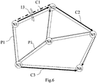
- Fig.1 represents a portion of an optical network 1 comprising six nodes (N1, N2, N3, N4, N5, N6) connected by optical links 3. Three connections (C1, C2, C3) are established and correspond to working connections. In the present invention, it is supposed that C1, C2 and C3 have disjoint paths.
- protecting connections corresponding to the connection of the source and the destination of the working connection but using a different path, have to be foreseen in order to provide sparing solutions in case of failure in a working connection.
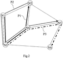
- Such protecting connections P1, P2, P3 are represented in Fig.2 according to the example of Fig.1 .
- P1, P2 and P3 being respectively the protecting connections corresponding to C1, C2 and C3.
- the configuration presented in Fig.1 and Fig.2 corresponds to a situation wherein working connections do not belong to a common shared risk link group and wherein the corresponding protecting connections have at least a partial common path.
- Working connections which do not belong to a common shared risk link group have paths that are partially or totally disjoint from each other such that the risk of both connection to have a failure at the same time is greatly reduced.
- the working and protecting connections are transmitted on the same wavelength channel and is the same for the three connections (which is possible thanks to the assumption that the working connections have disjoint path) in order to save CAPEX costs.
- working connections may have different wavelength channel but their protecting connection are transmitted on the same wavelength channel as the other protecting channel having at least a partial common path.
- protecting signals are merged as a single combined signal in order to be transmitted along the common path.
- the optical cross-connects located in the nodes of the network can perform transparent fusions by merging the received signals on a common output in order to produce the fusion of the received signals, the combined signal being then the cumulation of the received signals and can therefore be transmitted on a single wavelength channel.
- Fig.3 represents a portion of network wherein three signals Pa, Pb and Pc sent respectively from nodes N10, N11 and N13 are transmitted toward node N15. At node N12, Pa and Pb are combined to produce Pab and in node N14, Pab and Pc are combined to produce Pabc.
- the signals Pab and Pabc may refer to different signals in function of the node configuration as described by the following equations:
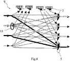
- Such fusion 5 can be achieved, for example, by wavelength selective switches (WSS) 7 such as presented in the optical cross connect 9 described in Fig.4 .
- WSS wavelength selective switches
- the combined signal may to one of the merged protecting signals or the fusion of said merged protecting signals.
- only one of the protecting signals can be transmitted as a combined signal along the common path due to the incapacity of the used WSS to perform a fusion of the incoming signals.
- the combined signal PC2 is split and broadcasted toward both directions.
- Such split 11 can also be achieved by wavelength selective switches (WSS) 7 as described in Fig.4 .
- WSS wavelength selective switches
- the combined signal PC2 is transmitted on one side to node N2 and on the other side to node N5 and then to node N6 as represented in Fig.5 .
- amplifiers and equalizers can be used in order to adjust the signal power at the output of a node after a split 11 or a fusion 5.
- the idea of the embodiments of the present invention is to block the other protecting signals along the path in order to retrieve the signal corresponding to P1 at node N2. Such blocking may be achieved by the filtering function of the wavelength selective switches (WSS) 7. Thus, at node N1, the signal corresponding to the protecting connection P2 is blocked such that the combined signal PC1 corresponds to the signal P1.
- WSS wavelength selective switches
- the signal corresponding to the protecting connection P3 is blocked such that the combined signal PC2 corresponds to the signal P1.
- the signal received at node N2 corresponds to the signal P1 and the failing connection C1 is therefore replaced by the protecting connection P1.
- the delay of the protection is reduced and corresponds to the time required for the wavelength selective switches (WSS) 7 to be aware of the failure and to transmit the selected signal (P1 in the present example) and block the unselected signals (P2 and P3 in the present example) at the merging points along the path of the protecting connection corresponding to the selected protection.
- the signalization process refers to the following steps:
- the embodiments of the present invention by sharing a wavelength channel between different protecting signals having at least a partial common path allow to reduce the CAPEX costs with respect to a 1+1 protection scheme (using a wavelength channel for each protecting signal) while providing a reduced protection delay with respect to the protection schemes in which the protecting signals are not active before failure.
- the offered protection solution provides a new trade-off allowing reducing the protection delay while limiting the cost of said protection.
Landscapes
- Engineering & Computer Science (AREA)
- Computer Networks & Wireless Communication (AREA)
- Signal Processing (AREA)
- Optical Communication System (AREA)
Claims (13)
- Verfahren zum Erzeugen eines Satzes von Schutzverbindungen (P1, P2, P3) in einem optischen Netzwerk (1), um Schutz eines Satzes von Arbeitsverbindungen (C1, C2, C3) zu gewährleisten, wobei die Schutzverbindungen (P1, P2, P3) einen von den Arbeitsverbindungen (C1, C2, C3) unterschiedlichen Pfad aufweisen, wobei:- die Arbeitsverbindungen (C1, C2, C3) des Satzes teilweise oder vollständig getrennte Pfade aufweisen,- die Schutzverbindungen (P1, P2, P3) auf demselben Wellenlängenkanal gesendet werden,- die Signale von mindestens zwei Schutzverbindungen (P1, P2, P3), die mindestens einen teilweise gemeinsamen Pfad aufweisen, transparent in ein Kombinationssignal (PC1, PC2) vereint und auf einem gemeinsamen Wellenlängenkanal entlang dem mindestens teilweise gemeinsamen Pfad gesendet werden.
- Verfahren zum Erzeugen eines Satzes von Schutzverbindungen in einem optischen Netzwerk nach Anspruch 1, wobei für zwei Arbeitsverbindungen in einer gemeinsam genutzten Risikoverbindungsstreckengruppe die entsprechenden Schutzverbindungen auf zwei unterschiedlichen Wellenlängenkanälen gesendet werden.
- Verfahren zum Erzeugen eines Satzes von Schutzverbindungen in einem optischen Netzwerk nach Anspruch 1 oder 2, wobei ein Kombinationssignal von vereinten Signalen einem der vereinten Signale oder einer Kumulation der vereinten Signale entspricht.
- Verfahren zum Erzeugen eines Satzes von Schutzverbindungen in einem optischen Netzwerk nach einem der vorhergehenden Ansprüche, wobei Kombinationssignale an verschiedene Ziele der verschiedenen in den Kombinationssignalen vereinten Schutzsignale gesendet werden.
- Verfahren zum Erzeugen eines Satzes von Schutzverbindungen in einem optischen Netzwerk nach einem der vorhergehenden Ansprüche, wobei im Falle eines Versagens einer Arbeitsverbindung die entsprechende Schutzverbindung durch Senden des entsprechenden Schutzsignals und Blockieren der anderen Signale an den Vereinigungspunkten entlang der Schutzverbindungen aufgesetzt wird.
- Verfahren zum Erzeugen eines Satzes von Schutzverbindungen in einem optischen Netzwerk nach einem der vorhergehenden Ansprüche, wobei die Handlung des Vereinens von Signalen in ein Kombinationssignal und auf einem gemeinsamen Wellenlängenkanal durch wellenlängenselektive Schalter, WSS, (7) erreicht wird.
- Verfahren zum Erzeugen eines Satzes von Schutzverbindungen in einem optischen Netzwerk nach einem der vorhergehenden Ansprüche, wobei die Handlung des Vereinens von Signalen in ein Kombinationssignal und auf einem gemeinsamen Wellenlängenkanal durch optische Koppler erreicht wird.
- Verfahren zum Erzeugen eines Satzes von Schutzverbindungen in einem optischen Netzwerk nach einem der vorhergehenden Ansprüche im Kombination mit Anspruch 4, wobei die Handlung des Sendens eines Kombinationssignals an verschiedene Ziele durch wellenlängenselektive Schalter, WSS, (7) erreicht wird.
- Verfahren zum Erzeugen eines Satzes von Schutzverbindungen in einem optischen Netzwerk nach einem der vorhergehenden Ansprüche im Kombination mit Anspruch 4, wobei die Handlung des Sendens eines Kombinationssignals an verschiedene Ziele durch optische Koppler erreicht wird.
- Verfahren zum Erzeugen eines Satzes von Schutzverbindungen in einem optischen Netzwerk nach nach einem der vorhergehenden Ansprüche im Kombination mit Anspruch 5, wobei die Handlung des Blockierens von Signalen an Vereinigungspunkten entlang einer Schutzverbindung durch wellenlängenselektive Schalter, WSS, (7) erreicht wird.
- Wellenlängenselektiver Schalter, WSS, (7), umfassend mehrere Eingänge, die ausgelegt sind zum Empfangen von Schutzverbindungen (P1, P2, P3), die mindestens einen teilweise gemeinsamen Pfad aufweisen, und einen Ausgang, der ausgelegt ist zum Senden von Schutzverbindungen (P1, P2, P3), wobei der WSS auch ein Mittel, das ausgelegt ist zum Erstellen einer Kumulation von mindestens zwei Signalen, die an den Eingängen empfangenen Schutzverbindungen (P1, P2, P3) entsprechen, und ein Mittel, das ausgelegt ist zum Senden eines sich aus der Kumulation ergebenden Signals an dem Ausgang, umfasst.
- Wellenlängenselektiver Schalter, WSS, (7) nach Anspruch 11, wobei der WSS auch ein Mittel umfasst, das ausgelegt ist zum Rundsenden eines an dem Eingang empfangenen Signals an mindestens zwei verschiedene Ausgänge.
- Optische Überkreuzverbindung, OXC, (9), umfassend mindestens einen wellenlängenselektiven Schalter, WSS, (7) nach Anspruch 11 und mindestens einen wellenlängenselektiven Schalter, WSS, (7) nach Anspruch 12, wobei die wellenlängenselektiven Schalter, WSS, (7) kombiniert sind, um die Kumulation von mindestens zwei empfangenen Signalen auf einem gemeinsamen Ausgang und das Rundsenden eines empfangenen Signals auf mindestens zwei verschiedenen Ausgängen zu erlauben.
Priority Applications (1)
| Application Number | Priority Date | Filing Date | Title |
|---|---|---|---|
| EP09290785.6A EP2312781B1 (de) | 2009-10-15 | 2009-10-15 | Verfahren zum Erzeugen eines Satzes von Schutzverbindungen |
Applications Claiming Priority (1)
| Application Number | Priority Date | Filing Date | Title |
|---|---|---|---|
| EP09290785.6A EP2312781B1 (de) | 2009-10-15 | 2009-10-15 | Verfahren zum Erzeugen eines Satzes von Schutzverbindungen |
Publications (2)
| Publication Number | Publication Date |
|---|---|
| EP2312781A1 EP2312781A1 (de) | 2011-04-20 |
| EP2312781B1 true EP2312781B1 (de) | 2018-08-29 |
Family
ID=41724671
Family Applications (1)
| Application Number | Title | Priority Date | Filing Date |
|---|---|---|---|
| EP09290785.6A Not-in-force EP2312781B1 (de) | 2009-10-15 | 2009-10-15 | Verfahren zum Erzeugen eines Satzes von Schutzverbindungen |
Country Status (1)
| Country | Link |
|---|---|
| EP (1) | EP2312781B1 (de) |
Family Cites Families (3)
| Publication number | Priority date | Publication date | Assignee | Title |
|---|---|---|---|---|
| US6643464B1 (en) * | 1999-07-07 | 2003-11-04 | Nortel Networks Limited | Constrained optical mesh protection for transmission systems |
| US7606237B2 (en) * | 2003-03-31 | 2009-10-20 | Alcatel-Lucent Usa Inc. | Sharing restoration path bandwidth in mesh networks |
| FR2897491B1 (fr) * | 2006-02-16 | 2008-05-09 | Alcatel Sa | Dispositif de combinaison/recombinaison de bits pour la protection de trafic dans un noeud d'un reseau de communication |
-
2009
- 2009-10-15 EP EP09290785.6A patent/EP2312781B1/de not_active Not-in-force
Also Published As
| Publication number | Publication date |
|---|---|
| EP2312781A1 (de) | 2011-04-20 |
Similar Documents
| Publication | Publication Date | Title |
|---|---|---|
| US7274869B1 (en) | System and method for providing destination-to-source protection switch setup in optical network topologies | |
| US6657952B1 (en) | Ring network for sharing protection resource by working communication paths | |
| EP3022857B1 (de) | Verfahren und vorrichtung für lokalen pfadschutz | |
| EP1161014A1 (de) | Selbstschützendes optisches Nachrichtenübertragungs-Ringnetzwerk | |
| US10498479B2 (en) | Reconfigurable add/drop multiplexing in optical networks | |
| KR100875934B1 (ko) | 멀티링 네트워크 운영방법 및 장치 | |
| CN101729182B (zh) | 单纤双向环网保护方法、系统及装置 | |
| JP2020048177A (ja) | Roadmサービス側の光ファイバ接続をマッチングさせるための装置および方法 | |
| US20060133804A1 (en) | Method and apparatus for protecting optical signals within a wavelength division multiplexed environment | |
| US6579018B1 (en) | Four-fiber ring optical cross connect system using 4×4 switch matrices | |
| EP3057247B1 (de) | Vorrichtung für rekonfigurierbaren optischen add/drop-multiplexer | |
| EP2151931A1 (de) | Wellenlängenuntereilungs-Multiplexer und regeneratives Wiederholungsverfahren in einem Multiplexing-Netzwerk zur Wellenlängenaufteilung | |
| US6185021B1 (en) | Cross-connecting optical translator array | |
| US7787763B2 (en) | System and method for protecting optical light-trails | |
| US7272311B2 (en) | Optical ring network for burst data communication | |
| EP1715609A1 (de) | Vorrichtung zur implementierung eines gemeinsam benutzten optischen kanalschutzes in wdm-systemen und verfahren dafür | |
| JP3993591B2 (ja) | 両方向波長分割多重方式のアッド/ドロップ自己回復ハブ形環状網 | |
| EP1453234A2 (de) | Vorrichtung und Verfahren zur optischen Kommunikation | |
| JP2012151603A (ja) | 光伝送装置 | |
| EP2312781A1 (de) | Verfahren zum Erzeugen eines Satzes von Schutzverbindungen | |
| CA2448641A1 (en) | Virtual protection channel for fiber optic ring network | |
| US8149687B2 (en) | Intra-node fault recovery within a multi-stage switching architecture | |
| JP2008545334A (ja) | ネットワークデータプレーン内の隣接ネットワーク素子の発見 | |
| US20030039433A1 (en) | Optical communication circuit | |
| KR20140123712A (ko) | 광통신 장치, 그리고 이의 보호 절체 방법 |
Legal Events
| Date | Code | Title | Description |
|---|---|---|---|
| PUAI | Public reference made under article 153(3) epc to a published international application that has entered the european phase |
Free format text: ORIGINAL CODE: 0009012 |
|
| AK | Designated contracting states |
Kind code of ref document: A1 Designated state(s): AT BE BG CH CY CZ DE DK EE ES FI FR GB GR HR HU IE IS IT LI LT LU LV MC MK MT NL NO PL PT RO SE SI SK SM TR |
|
| AX | Request for extension of the european patent |
Extension state: AL BA RS |
|
| 17P | Request for examination filed |
Effective date: 20111020 |
|
| RAP1 | Party data changed (applicant data changed or rights of an application transferred) |
Owner name: ALCATEL LUCENT |
|
| 111Z | Information provided on other rights and legal means of execution |
Free format text: AT BE BG CH CY CZ DE DK EE ES FI FR GB GR HR HU IE IS IT LI LT LU LV MC MK MT NL NO PL PT RO SE SI SK SM TR Effective date: 20130410 |
|
| RAP1 | Party data changed (applicant data changed or rights of an application transferred) |
Owner name: ALCATEL LUCENT |
|
| D11X | Information provided on other rights and legal means of execution (deleted) | ||
| STAA | Information on the status of an ep patent application or granted ep patent |
Free format text: STATUS: EXAMINATION IS IN PROGRESS |
|
| 17Q | First examination report despatched |
Effective date: 20170217 |
|
| GRAP | Despatch of communication of intention to grant a patent |
Free format text: ORIGINAL CODE: EPIDOSNIGR1 |
|
| STAA | Information on the status of an ep patent application or granted ep patent |
Free format text: STATUS: GRANT OF PATENT IS INTENDED |
|
| INTG | Intention to grant announced |
Effective date: 20180205 |
|
| RIN1 | Information on inventor provided before grant (corrected) |
Inventor name: MOREA, ANNALISA Inventor name: DOUVILLE, RICHARD Inventor name: ZAMI, THIERRY |
|
| RAP1 | Party data changed (applicant data changed or rights of an application transferred) |
Owner name: ALCATEL LUCENT |
|
| GRAS | Grant fee paid |
Free format text: ORIGINAL CODE: EPIDOSNIGR3 |
|
| GRAJ | Information related to disapproval of communication of intention to grant by the applicant or resumption of examination proceedings by the epo deleted |
Free format text: ORIGINAL CODE: EPIDOSDIGR1 |
|
| GRAL | Information related to payment of fee for publishing/printing deleted |
Free format text: ORIGINAL CODE: EPIDOSDIGR3 |
|
| STAA | Information on the status of an ep patent application or granted ep patent |
Free format text: STATUS: EXAMINATION IS IN PROGRESS |
|
| GRAR | Information related to intention to grant a patent recorded |
Free format text: ORIGINAL CODE: EPIDOSNIGR71 |
|
| STAA | Information on the status of an ep patent application or granted ep patent |
Free format text: STATUS: GRANT OF PATENT IS INTENDED |
|
| INTC | Intention to grant announced (deleted) | ||
| GRAA | (expected) grant |
Free format text: ORIGINAL CODE: 0009210 |
|
| STAA | Information on the status of an ep patent application or granted ep patent |
Free format text: STATUS: THE PATENT HAS BEEN GRANTED |
|
| RAP1 | Party data changed (applicant data changed or rights of an application transferred) |
Owner name: PROVENANCE ASSET GROUP LLC |
|
| AK | Designated contracting states |
Kind code of ref document: B1 Designated state(s): AT BE BG CH CY CZ DE DK EE ES FI FR GB GR HR HU IE IS IT LI LT LU LV MC MK MT NL NO PL PT RO SE SI SK SM TR |
|
| INTG | Intention to grant announced |
Effective date: 20180720 |
|
| REG | Reference to a national code |
Ref country code: GB Ref legal event code: FG4D |
|
| REG | Reference to a national code |
Ref country code: CH Ref legal event code: EP |
|
| REG | Reference to a national code |
Ref country code: AT Ref legal event code: REF Ref document number: 1036406 Country of ref document: AT Kind code of ref document: T Effective date: 20180915 |
|
| REG | Reference to a national code |
Ref country code: IE Ref legal event code: FG4D |
|
| REG | Reference to a national code |
Ref country code: DE Ref legal event code: R096 Ref document number: 602009054136 Country of ref document: DE |
|
| REG | Reference to a national code |
Ref country code: NL Ref legal event code: MP Effective date: 20180829 |
|
| REG | Reference to a national code |
Ref country code: LT Ref legal event code: MG4D |
|
| PG25 | Lapsed in a contracting state [announced via postgrant information from national office to epo] |
Ref country code: NO Free format text: LAPSE BECAUSE OF FAILURE TO SUBMIT A TRANSLATION OF THE DESCRIPTION OR TO PAY THE FEE WITHIN THE PRESCRIBED TIME-LIMIT Effective date: 20181129 Ref country code: SE Free format text: LAPSE BECAUSE OF FAILURE TO SUBMIT A TRANSLATION OF THE DESCRIPTION OR TO PAY THE FEE WITHIN THE PRESCRIBED TIME-LIMIT Effective date: 20180829 Ref country code: FI Free format text: LAPSE BECAUSE OF FAILURE TO SUBMIT A TRANSLATION OF THE DESCRIPTION OR TO PAY THE FEE WITHIN THE PRESCRIBED TIME-LIMIT Effective date: 20180829 Ref country code: LT Free format text: LAPSE BECAUSE OF FAILURE TO SUBMIT A TRANSLATION OF THE DESCRIPTION OR TO PAY THE FEE WITHIN THE PRESCRIBED TIME-LIMIT Effective date: 20180829 Ref country code: GR Free format text: LAPSE BECAUSE OF FAILURE TO SUBMIT A TRANSLATION OF THE DESCRIPTION OR TO PAY THE FEE WITHIN THE PRESCRIBED TIME-LIMIT Effective date: 20181130 Ref country code: IS Free format text: LAPSE BECAUSE OF FAILURE TO SUBMIT A TRANSLATION OF THE DESCRIPTION OR TO PAY THE FEE WITHIN THE PRESCRIBED TIME-LIMIT Effective date: 20181229 Ref country code: NL Free format text: LAPSE BECAUSE OF FAILURE TO SUBMIT A TRANSLATION OF THE DESCRIPTION OR TO PAY THE FEE WITHIN THE PRESCRIBED TIME-LIMIT Effective date: 20180829 Ref country code: BG Free format text: LAPSE BECAUSE OF FAILURE TO SUBMIT A TRANSLATION OF THE DESCRIPTION OR TO PAY THE FEE WITHIN THE PRESCRIBED TIME-LIMIT Effective date: 20181129 |
|
| REG | Reference to a national code |
Ref country code: AT Ref legal event code: MK05 Ref document number: 1036406 Country of ref document: AT Kind code of ref document: T Effective date: 20180829 |
|
| PG25 | Lapsed in a contracting state [announced via postgrant information from national office to epo] |
Ref country code: ES Free format text: LAPSE BECAUSE OF FAILURE TO SUBMIT A TRANSLATION OF THE DESCRIPTION OR TO PAY THE FEE WITHIN THE PRESCRIBED TIME-LIMIT Effective date: 20180829 Ref country code: LV Free format text: LAPSE BECAUSE OF FAILURE TO SUBMIT A TRANSLATION OF THE DESCRIPTION OR TO PAY THE FEE WITHIN THE PRESCRIBED TIME-LIMIT Effective date: 20180829 Ref country code: HR Free format text: LAPSE BECAUSE OF FAILURE TO SUBMIT A TRANSLATION OF THE DESCRIPTION OR TO PAY THE FEE WITHIN THE PRESCRIBED TIME-LIMIT Effective date: 20180829 |
|
| PG25 | Lapsed in a contracting state [announced via postgrant information from national office to epo] |
Ref country code: EE Free format text: LAPSE BECAUSE OF FAILURE TO SUBMIT A TRANSLATION OF THE DESCRIPTION OR TO PAY THE FEE WITHIN THE PRESCRIBED TIME-LIMIT Effective date: 20180829 Ref country code: PL Free format text: LAPSE BECAUSE OF FAILURE TO SUBMIT A TRANSLATION OF THE DESCRIPTION OR TO PAY THE FEE WITHIN THE PRESCRIBED TIME-LIMIT Effective date: 20180829 Ref country code: RO Free format text: LAPSE BECAUSE OF FAILURE TO SUBMIT A TRANSLATION OF THE DESCRIPTION OR TO PAY THE FEE WITHIN THE PRESCRIBED TIME-LIMIT Effective date: 20180829 Ref country code: IT Free format text: LAPSE BECAUSE OF FAILURE TO SUBMIT A TRANSLATION OF THE DESCRIPTION OR TO PAY THE FEE WITHIN THE PRESCRIBED TIME-LIMIT Effective date: 20180829 Ref country code: CZ Free format text: LAPSE BECAUSE OF FAILURE TO SUBMIT A TRANSLATION OF THE DESCRIPTION OR TO PAY THE FEE WITHIN THE PRESCRIBED TIME-LIMIT Effective date: 20180829 Ref country code: AT Free format text: LAPSE BECAUSE OF FAILURE TO SUBMIT A TRANSLATION OF THE DESCRIPTION OR TO PAY THE FEE WITHIN THE PRESCRIBED TIME-LIMIT Effective date: 20180829 |
|
| PG25 | Lapsed in a contracting state [announced via postgrant information from national office to epo] |
Ref country code: SK Free format text: LAPSE BECAUSE OF FAILURE TO SUBMIT A TRANSLATION OF THE DESCRIPTION OR TO PAY THE FEE WITHIN THE PRESCRIBED TIME-LIMIT Effective date: 20180829 Ref country code: DK Free format text: LAPSE BECAUSE OF FAILURE TO SUBMIT A TRANSLATION OF THE DESCRIPTION OR TO PAY THE FEE WITHIN THE PRESCRIBED TIME-LIMIT Effective date: 20180829 Ref country code: SM Free format text: LAPSE BECAUSE OF FAILURE TO SUBMIT A TRANSLATION OF THE DESCRIPTION OR TO PAY THE FEE WITHIN THE PRESCRIBED TIME-LIMIT Effective date: 20180829 |
|
| REG | Reference to a national code |
Ref country code: CH Ref legal event code: PL Ref country code: DE Ref legal event code: R097 Ref document number: 602009054136 Country of ref document: DE |
|
| REG | Reference to a national code |
Ref country code: BE Ref legal event code: MM Effective date: 20181031 |
|
| PG25 | Lapsed in a contracting state [announced via postgrant information from national office to epo] |
Ref country code: LU Free format text: LAPSE BECAUSE OF NON-PAYMENT OF DUE FEES Effective date: 20181015 Ref country code: MC Free format text: LAPSE BECAUSE OF FAILURE TO SUBMIT A TRANSLATION OF THE DESCRIPTION OR TO PAY THE FEE WITHIN THE PRESCRIBED TIME-LIMIT Effective date: 20180829 |
|
| PLBE | No opposition filed within time limit |
Free format text: ORIGINAL CODE: 0009261 |
|
| STAA | Information on the status of an ep patent application or granted ep patent |
Free format text: STATUS: NO OPPOSITION FILED WITHIN TIME LIMIT |
|
| REG | Reference to a national code |
Ref country code: IE Ref legal event code: MM4A |
|
| 26N | No opposition filed |
Effective date: 20190531 |
|
| PG25 | Lapsed in a contracting state [announced via postgrant information from national office to epo] |
Ref country code: CH Free format text: LAPSE BECAUSE OF NON-PAYMENT OF DUE FEES Effective date: 20181031 Ref country code: FR Free format text: LAPSE BECAUSE OF NON-PAYMENT OF DUE FEES Effective date: 20181029 Ref country code: BE Free format text: LAPSE BECAUSE OF NON-PAYMENT OF DUE FEES Effective date: 20181031 Ref country code: SI Free format text: LAPSE BECAUSE OF FAILURE TO SUBMIT A TRANSLATION OF THE DESCRIPTION OR TO PAY THE FEE WITHIN THE PRESCRIBED TIME-LIMIT Effective date: 20180829 Ref country code: LI Free format text: LAPSE BECAUSE OF NON-PAYMENT OF DUE FEES Effective date: 20181031 |
|
| PG25 | Lapsed in a contracting state [announced via postgrant information from national office to epo] |
Ref country code: IE Free format text: LAPSE BECAUSE OF NON-PAYMENT OF DUE FEES Effective date: 20181015 |
|
| PG25 | Lapsed in a contracting state [announced via postgrant information from national office to epo] |
Ref country code: MT Free format text: LAPSE BECAUSE OF NON-PAYMENT OF DUE FEES Effective date: 20181015 |
|
| PG25 | Lapsed in a contracting state [announced via postgrant information from national office to epo] |
Ref country code: TR Free format text: LAPSE BECAUSE OF FAILURE TO SUBMIT A TRANSLATION OF THE DESCRIPTION OR TO PAY THE FEE WITHIN THE PRESCRIBED TIME-LIMIT Effective date: 20180829 |
|
| PG25 | Lapsed in a contracting state [announced via postgrant information from national office to epo] |
Ref country code: PT Free format text: LAPSE BECAUSE OF FAILURE TO SUBMIT A TRANSLATION OF THE DESCRIPTION OR TO PAY THE FEE WITHIN THE PRESCRIBED TIME-LIMIT Effective date: 20180829 |
|
| PG25 | Lapsed in a contracting state [announced via postgrant information from national office to epo] |
Ref country code: HU Free format text: LAPSE BECAUSE OF FAILURE TO SUBMIT A TRANSLATION OF THE DESCRIPTION OR TO PAY THE FEE WITHIN THE PRESCRIBED TIME-LIMIT; INVALID AB INITIO Effective date: 20091015 Ref country code: MK Free format text: LAPSE BECAUSE OF NON-PAYMENT OF DUE FEES Effective date: 20180829 Ref country code: CY Free format text: LAPSE BECAUSE OF FAILURE TO SUBMIT A TRANSLATION OF THE DESCRIPTION OR TO PAY THE FEE WITHIN THE PRESCRIBED TIME-LIMIT Effective date: 20180829 |
|
| PGFP | Annual fee paid to national office [announced via postgrant information from national office to epo] |
Ref country code: DE Payment date: 20201027 Year of fee payment: 12 Ref country code: GB Payment date: 20201029 Year of fee payment: 12 |
|
| REG | Reference to a national code |
Ref country code: DE Ref legal event code: R119 Ref document number: 602009054136 Country of ref document: DE |
|
| GBPC | Gb: european patent ceased through non-payment of renewal fee |
Effective date: 20211015 |
|
| PG25 | Lapsed in a contracting state [announced via postgrant information from national office to epo] |
Ref country code: GB Free format text: LAPSE BECAUSE OF NON-PAYMENT OF DUE FEES Effective date: 20211015 Ref country code: DE Free format text: LAPSE BECAUSE OF NON-PAYMENT OF DUE FEES Effective date: 20220503 |