EP2311751A2 - A display pack and packaging method and apparatus - Google Patents
A display pack and packaging method and apparatus Download PDFInfo
- Publication number
- EP2311751A2 EP2311751A2 EP10013746A EP10013746A EP2311751A2 EP 2311751 A2 EP2311751 A2 EP 2311751A2 EP 10013746 A EP10013746 A EP 10013746A EP 10013746 A EP10013746 A EP 10013746A EP 2311751 A2 EP2311751 A2 EP 2311751A2
- Authority
- EP
- European Patent Office
- Prior art keywords
- rim
- platens
- rollers
- platen
- cardboard
- Prior art date
- Legal status (The legal status is an assumption and is not a legal conclusion. Google has not performed a legal analysis and makes no representation as to the accuracy of the status listed.)
- Granted
Links
- 238000004806 packaging method and process Methods 0.000 title description 21
- 238000000034 method Methods 0.000 title description 19
- 238000007789 sealing Methods 0.000 claims abstract description 32
- 230000007246 mechanism Effects 0.000 claims abstract description 20
- 239000011111 cardboard Substances 0.000 claims description 88
- 230000002093 peripheral effect Effects 0.000 claims description 22
- 238000010438 heat treatment Methods 0.000 claims description 14
- 230000007723 transport mechanism Effects 0.000 claims description 10
- 239000000853 adhesive Substances 0.000 description 47
- 230000001070 adhesive effect Effects 0.000 description 47
- 239000000463 material Substances 0.000 description 22
- 238000003780 insertion Methods 0.000 description 13
- 230000037431 insertion Effects 0.000 description 13
- 239000003292 glue Substances 0.000 description 7
- 239000000123 paper Substances 0.000 description 7
- 238000007796 conventional method Methods 0.000 description 6
- 239000012943 hotmelt Substances 0.000 description 4
- 239000004020 conductor Substances 0.000 description 2
- 230000000994 depressogenic effect Effects 0.000 description 2
- 238000001035 drying Methods 0.000 description 2
- 238000004519 manufacturing process Methods 0.000 description 2
- 238000012986 modification Methods 0.000 description 2
- 230000004048 modification Effects 0.000 description 2
- 238000004064 recycling Methods 0.000 description 2
- 238000005452 bending Methods 0.000 description 1
- 239000011248 coating agent Substances 0.000 description 1
- 238000000576 coating method Methods 0.000 description 1
- 239000003086 colorant Substances 0.000 description 1
- 238000001816 cooling Methods 0.000 description 1
- 239000007787 solid Substances 0.000 description 1
- 238000012360 testing method Methods 0.000 description 1
- 238000012546 transfer Methods 0.000 description 1
Images


Classifications
-
- B—PERFORMING OPERATIONS; TRANSPORTING
- B65—CONVEYING; PACKING; STORING; HANDLING THIN OR FILAMENTARY MATERIAL
- B65D—CONTAINERS FOR STORAGE OR TRANSPORT OF ARTICLES OR MATERIALS, e.g. BAGS, BARRELS, BOTTLES, BOXES, CANS, CARTONS, CRATES, DRUMS, JARS, TANKS, HOPPERS, FORWARDING CONTAINERS; ACCESSORIES, CLOSURES, OR FITTINGS THEREFOR; PACKAGING ELEMENTS; PACKAGES
- B65D73/00—Packages comprising articles attached to cards, sheets or webs
- B65D73/0078—Packages comprising articles attached to cards, sheets or webs the articles being retained or enclosed in a folded-over or doubled card
- B65D73/0085—Packages comprising articles attached to cards, sheets or webs the articles being retained or enclosed in a folded-over or doubled card within a window, hole or cut-out portion
- B65D73/0092—Packages comprising articles attached to cards, sheets or webs the articles being retained or enclosed in a folded-over or doubled card within a window, hole or cut-out portion combined with a preformed enclosure, e.g. a bulb
-
- B—PERFORMING OPERATIONS; TRANSPORTING
- B65—CONVEYING; PACKING; STORING; HANDLING THIN OR FILAMENTARY MATERIAL
- B65B—MACHINES, APPARATUS OR DEVICES FOR, OR METHODS OF, PACKAGING ARTICLES OR MATERIALS; UNPACKING
- B65B51/00—Devices for, or methods of, sealing or securing package folds or closures; Devices for gathering or twisting wrappers, or necks of bags
- B65B51/10—Applying or generating heat or pressure or combinations thereof
- B65B51/14—Applying or generating heat or pressure or combinations thereof by reciprocating or oscillating members
Definitions
- This invention relates to product packaging, and in particular, it relates to packaging for products suitable for store merchandising.
- a first type of conventional packaging for consumer products is made of two sheets of corrugated cardboard 101 and 102, and a clear plastic container 103 having a flat insertion portion 103a and a chamber portion 103b.
- the insertion portion is sandwiched between the two cardboard sheets 101 and 102, and the chamber portion 103b protrudes from the plane of the cardboard sheets via a cut (opening) on one cardboard sheet 101 and is used to hold the product inside.
- a second plastic container 103' may be provided and protrudes from the other cardboard sheet 102 to form a continuous space for hold the product.
- the two cardboard sheets 101 and 102 are adhered together around the periphery with an adhesive 104.
- a commonly used adhesive is a hot melt glue.
- the front and back sides of the package are typically printed with product information and other information. (In these drawings, the spaces between the various layers are exaggerated to illustrate the relationship among the various layers.)
- One disadvantage of this type of conventional packaging is that the hot melt glue is typically applied by hand, and thus the seal quality is often difficult to control due to, for example, the varying drying speed of the glue, the placement of the glue, etc.
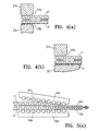
- Another disadvantage is that the corrugation of the cardboard is visible at some of the side edges of the finished packaging (see Fig. 6(c) , a view of the bottom edge of the packaging of Fig. 6(a) ), making the packaging aesthetically unappealing.
- a second type of conventional packaging shown in Fig. 7(a) is similar to the first type shown in Figs. 6(a)-(c) , but uses one sheet of corrugated cardboard 112 (typically the back sheet) and one flat sheet of paper 111 (typically the front sheet, i.e., on the side of the product chamber). Sometimes two flat sheets of paper 111 and 111' are used, one on each side of the corrugated cardboard (see Fig. 7(b) . The cardboard sheet 112 and the flat paper sheet 111 are adhered together by a heat-sensitive adhesive 114 to seal the package.
- a heat-sensitive adhesive 114 to seal the package.
- the heat sensitive adhesive is pre-applied to the cardboard sheet and/or the flat paper sheet, and heat is applied from the paper side, conducted to the adhesive via the paper to activate the adhesive.
- Heat sensitive adhesives have not been used in the first type of packaging because corrugated cardboard sheets are poor heat conductors, and heat applied to the outer side of the cardboard cannot easily reach the area between the two cardboard sheets where the heat adhesive material would be applied.
- a disadvantage of the second type of conventional packaging is that it sometimes lacks sufficient structural strength.
- Display packs are often transported in an assembly where a plurality of display packs are stood on their sides in a container with half-height walls (i.e. walls not as high as the packs themselves), and wrapped together to form a box-shaped bundle. When two or more of such bundles are stacked on top of each other, the weight of the top one is supported directly by the packs in the bottom bundle.
- the packs therefore must have sufficient structural strength and rigidity to prevent them from bending.
- the lack of physical strength also makes it difficult to make larger packages (e.g. larger than 10 by 15 inches), or to pack heavier items.
- the present invention is directed to a display pack and packaging method that substantially obviates one or more of the problems due to limitations and disadvantages of the related art.
- the present invention provides a display pack for a product including a first and a second corrugated cardboard sheet, at least one cardboard sheet defining at least one opening; at least one container having a flat insertion portion and a chamber portion for holding the product, the insertion portion being sandwiched between the two cardboard sheets and the chamber portion protruding from a plane of the cardboard sheets via the opening; and an adhesive material between the first and the second cardboard sheets in at least a peripheral area of the two cardboard sheets to join the two cardboard sheets together, wherein the first and second cardboard sheets are crushed in the peripheral area with reduced air gaps in the corrugations.
- the adhesive material may be a heat-sensitive adhesive material.
- the present invention provides a method of making a display pack including the steps of providing a first and a second corrugated cardboard sheet, at least one cardboard sheet defining at least one opening; providing at least one container having a flat insertion portion and a chamber portion for holding the product; placing the insertion portion between the two cardboard sheets so that the chamber portion protrudes from a plane of the cardboard sheets via the opening; applying an adhesive material between the first and second cardboard sheets in a peripheral area of the cardboard sheets; and applying a pressure to the peripheral area of the two cardboard sheets to crush the corrugations inside the cardboard sheets in the peripheral area.
- the adhesive material may be a heat-sensitive adhesive material, in which case the method further includes applying heat to the heat-sensitive adhesive to activate it.
- the present invention provides a device for sealing a display pack, which includes an upper and a lower platen, at least one of the platens having a rim and a recessed central area; and a drive mechanism for driving the platens, the drive mechanism capable of applying a force of 25 tons or more at the platens.
- the platens may be heated.
- the present invention provides another device for sealing a display pack, which includes a transport mechanism for transporting a package; one or more sets of rollers disposed along a path of the transport mechanism, each set of rollers including an upper row and an opposing lower row of rollers, the upper and lower rows of rollers disposed at a tapering angle with respect to each other; and a press for applying a force to at least one of the upper and lower rows of each set of rollers.
- the device may include two or four sets of rollers. The rollers may be heated.
- Fig. 1 shows a display pack according to an embodiment of the present invention which has an overall structure similar to that of a conventional packaging shown in Fig. 6(a) but is constructed differently.
- Figs. 2(a) and 2(b) are cross-sectional views of the display pack of Fig. 1 along the line 2-2 (the differences between Figs. 2(a) and 2(b) will be explained later).
- the package 1 is made of two sheets of corrugated cardboard 11 and 12 and a plastic container 13 (preferably made of a clear plastic material such as PET) having a flat insertion portion 13a and a chamber portion 13b.
- a package may contain one or more plastic containers, and they may protrude from either or both of the cardboard sheets and may be located are desired positions depending on the product being held in the package.
- a plastic container may be a single piece with multiple chambers.
- the container may be made of a plastic or any other suitable material, and can be of any suitable thickness, color, etc.
- the front and back sides of the package may be printed with product information and other information.
- the information may be printed directly on the cardboard, or printed on a litho sheet which is then laminated onto the cardboard.
- One to six colors can be printed.
- the corrugations are shown as being parallel to the vertical direction in Fig. 1 , which is preferably the vertical direction when the display pack is stood on its side when being displayed or transported. Of course, the corrugation can be in other directions.
- the corners of the cardboard sheets may be square, rounded, or a combination of both.
- the two corrugated cardboard sheets 11 and 12 are adhered together at the periphery of the package by a heat-sensitive adhesive 14 to seal the package.
- the heat-sensitive adhesive is preferably pre-applied to the inner sides of one or (preferably) both cardboard sheets 11 and 12 prior to the sealing operation, but it may also be applied during the sealing operation.
- the adhesive may be applied to the entire sheet, or a periphery, or any desired areas of the sheet.
- the cardboard sheets 11 and 12 are formed of one cardboard sheet folded over, the cardboard sheet being pre-coated with an adhesive on the entire surface.
- the peripheral areas 11a, 12a of the two overlaying cardboard sheets are subject to a sufficient amount of pressure to crush the corrugations inside the cardboard sheets and flatten them in that area.
- Heat is applied, either simultaneously with or subsequent to the application of pressure, to the outer side of either one or both cardboard sheets in the peripheral area. Because the corrugations inside the cardboard are crushed and the air gaps are substantially eliminated, the crushed cardboard becomes a better heat conductor. Sufficient heat can be conducted from the outer side to the inner side where the heat-sensitive adhesive has been applied to activate the adhesive and seal the package.
- the width of the crushed peripheral areas is approximately 0.5 inches.
- any suitable sealing width may be used, but it is desirable that the adhesive not be adhered to the insertion portion of the container, so that the container can be easily removed from the packaging for recycling. This is desirable because it facilitates recycling of the container.
- the container may be made as a re-usable container, and easy removal may facilitate re-use in such a case.
- the first is a sealer machine with a heated sealing press.
- the sealing press has an upper platen 21 and a lower platen 22.
- the lower platen 22 is show to have a rim 22a with a heated surface, a recessed central portion 23 that may accommodate the protrusions 13b of the package being sealed.
- the upper platen 21 similarly has a heated rim 21a and a recessed central portion (not shown).
- the rims have a width determined by the desired width of the crushed peripheral areas of the finished package.
- Alternative configurations of the sealing press may be used.
- one of the platens may have a flat surface without a recess, or have a rim wider than the rim of the other platen. If both the upper and lower platens have rims of similar widths, the crushed peripheral areas of the cardboard sheets may appear depressed on both sides (see Fig. 2(a) ). If one platen is flat or has a rim wider than the rim of the other platen, the crushed peripheral areas of the cardboard sheets may appear depressed only on the side of the narrower rim (see Fig. 2(b) ). In the platen configuration of Fig. 2(a) , one or both rim portions 21a and 22a may be heated. In the configuration of Fig. 2(b) , preferably only the narrower rim 21a is heated because it may be undesirable for areas other than the sealed peripheral areas to be heated. Heating from both sides may be more desirable as it reduces the heating time and speeds up the sealing operation.
- the force or pressure applied by the platens is such that the cardboard sheets are crushed to up to approximately 50% of their original thickness.
- higher pressure results in thinner crushed cardboard sheets, which in turn results in increased heat transfer rate and therefore reduced heat application time required to properly activate the adhesive.
- the optimum pressure may also depend on the type of the cardboard used.
- the temperature of the heated surface may be approximately from 100 to 500 degrees F, which is a typical temperature used in the second conventional packaging technique. Those of ordinary skill in the art will be able to find acceptable or optimum pressure, temperature and process time conditions for the particular cardboard used without undue experimentation.
- the package uses two sheets of 200 lb test E-flute cardboard coated with a heat sensitive blister card coating as an adhesive, has a size of 10 inches by 15 inches and a sealed width of 0.5 inches.
- the sealing press has a rim on both platens and both surfaces are heated to a temperature of 300 degrees F.
- the force on the platens is 25 tons. The pressure and heat was applied simultaneously for 3 seconds.
- the sealer machine suitable for the above application may be a machined used to seal a conventional package of the second type (as shown in Fig. 7(a) ), modified so that the platens can apply sufficient pressures to crush the cardboard.
- the machine has a pneumatically driven upper and lower toggle mechanism to create the pressure.
- the force on the platens is adjustable. In one example, the force is approximately between 10 and 75 tons.
- the upper and lower seal heat is generated with the use of multiple cartridge heaters controlled through solid state relays.
- the temperature of the upper surface is adjustable from 0 to 450 degrees F; the temperature of the lower surface is fixed at 450 degrees F. Additionally, there are chain driven elevators used to move the fixture that holds the packages during assembly and sealing back to the initial start position.
- a sealer press is provided with a number of posts 24 inside the area surrounded by the rim portion 21a and/or 22a. Opposing posts are provided if both platens have a recessed central portion; alternatively, if one platen is flat, the other platen is provided with the posts 24. The posts are pressured and heated in the same way as the rim portion.
- a second type of sealer machine useful for carrying out the sealing process is a sealing press similar to the one described above, but instead of heated platen(s), hot air or a hot steam is applied to the heat-sensitive adhesive to heat it.
- the hot air or steam is supplied from the side by a tube or pipe 25 as shown in Fig. 3(c) (cross-sectional view). Since a corrugated cardboard typically contains an adhesive to hold its various layers together, it is possible that the hot air or hot steam will melt this adhesive. Thus, after crushing, the layers of the crushed corrugated board will be adhered together by this adhesive, resulting in increased structural integrity of the seal.
- heated platen(s) and hot air/hot steam may be used in combination.
- Figs. 4(a) and 4(b) illustrate an alternative embodiment of the sealing press (either heated or unheated).
- the platens are similar to those shown in Figs. 2(a), 2(b) , 3(a) and 3(c) , but the rim portions 21a and 22a have rounded or chamfered edges 21b and 22b on the inside edges, i.e. the edges that correspond to the border between the crushed and uncrushed portions of the package.
- the rounded shape of the edges 21b and 22b avoids forming a sharp line between the crushed and uncrushed portions on the package and avoids potentially tearing or cutting the surface sheet of the cardboard. Desirable radius of the rounded edges 21b and 22b depends on the thickness of the corrugated boards, and is preferable about 1/8 to 1 inch. Note that Figs. 4(a) and 4(b) illustrate the stage of the platens before crushing occurs.
- FIG. 5(a)-(d) A third type of sealer machine according to an embodiment of the present invention is shown in Figs. 5(a)-(d) .
- Fig. 5(a) is a schematic cross sectional view along a side of a package to illustrate the side being sealed by a set of rollers of the sealer machine.
- the package contains two sheets of corrugated cardboard 11 and 12 with an adhesive (not shown) applied between the two sheets in the peripheral areas.
- the set of rollers of the sealer machine has opposing upper and lower rows of rollers 51a and 51 b mounted on respective roller blocks 52a and 52b.
- the upper and lower rows of rollers 51a and 51b are disposed at a tapering angle relative to each other such that gap between opposing rollers is slightly greater than the thickness of two sheets of uncrushed corrugated cardboard at the entrance end (the left hand side in Fig. 5(a) ), and is reduced to the desired thickness of the two sheets of crushed corrugated cardboard at the exit end.
- the angle and the gap are preferably adjustable.
- Fig. 5(a) shows the lower row of rollers 51b as being horizontal, but other designs are possible; for example, the upper row of rollers 51 a may be horizontal or neither row may be horizontal.
- a front segment of the two rows of rollers may be disposed at a tapering angle and a back segment thereof are disposed in parallel with a gap equal to the thickness of the crushed corrugated cardboard sheets.
- Sufficient pressure is applied to the roller blocks to crush the corrugations in the cardboard sheets and to seal the package.
- the upper roller block 52a is fixed and the lower roller block 52b is mounted on a hydraulic press capable of applying a force of about 0 to 75 tons, preferably about 20 to 70 tons. The force is preferably adjustable.
- One or both rows of rollers may be heated to a controllable temperature in a similar manner as the temperature control mechanism for the sealing press described earlier.
- rollers 5 1 a and 5 1 b may have rounded to chamfered inside edges to avoid potentially tearing or cutting the surface sheet of the cardboard.
- Fig. 5(b) is a schematic top plan view showing a parallel pair of roller sets 51a,b (collectively 51) and 53 mounted on a pair of roller blocks 52a,b (collectively 52) and 54 as well as a package 1 passing through the pair of roller sets.
- the structures of the roller set 53 and the roller block 54 are similar to those of the roller set 51 and the roller block 52.
- the lateral distance between the two roller sets 51 and 53 is adjustable to seal packages of different widths.
- the two roller sets 51 and 53 may be independent rollers; or alternatively, the lower rows of rollers in the roller sets 51 and 53 may be the same rollers that extend across the width of the package. In the latter case, only the distance between the upper rows of rollers will be adjusted for different package widths.
- the pair of roller sets shown in Fig. 5(b) can seal two parallel sides of a package.
- the package may be passed through another, similar sealer machine, or though the same pair of roller sets one more time (after adjusting the distance if necessary), or through an additional pair of roller sets of the same sealer machine.
- Figs. 5(c) and 5(d) show two preferred sealer machines each having two pairs of roller sets.
- a second pair of roller sets 55, 57 is provided downstream of and at the same orientation as the first pair of roller sets 51, 53.
- the package 1 is first transported by a transport mechanism in a first direction as indicated by the arrow A and sealed on two sides by the first pair of roller sets 51, 53.
- the package is rotated 90 degrees (as indicated by the arrow C) by a rotation mechanism and continues to move in the same direction (as indicated by the arrow D). It then passes through the second pair of roller sets 55,57 (as indicated by the arrow B) and is sealed on the other two sides.
- a second pair of roller sets 55, 57 is provided at a right angle with respect to the first pair of roller sets 51, 53.
- the package 1 is first transported in a first direction (as indicated by the arrow A) and sealed on two sides by the first pair of roller sets 51, 53, and then, without changing its orientation, is transported in a second direction (as indicated by the arrow B) at a right angle to the first direction.
- the package in Fig. 1 is shown to be sealed with the adhesive on all four sides.
- the package may be sealed in selected peripheral areas only.
- the two cardboard sheets 11 and 12 may be made of one board and folded once in the middle, and the side of the package corresponding to the fold line may not need to be sealed with the adhesive (although it is preferable to seal it as well).
- the platens of the sealing press may be constructed so that heat and pressure are only applied to the areas where seals are to be formed.
- the packaging technique according to embodiments of the present invention has the following advantages.
- the packages are more secure and harder to tear from the edge and the center than packages made by the first conventional method described above which uses hot melt glue.
- the sealing quality is also more consistent than seals using glue because the drying (cooling) speed and the placement of the hot melt glue are hard to control.
- Packages made with the present technique are also aesthetically more appealing than packages made by the first and second conventional techniques in that the corrugations of the cardboard sheets are less visible when viewed from the side edges (e.g. the bottom side) due to the crushing.
- packaging made with the present method is stronger because it uses two cardboard sheets. As a result, the packages can be made larger and to pack heavier items, and multiple packages can be stacked in bundles.
- the packages can be as large as 24x24 inches (whereas the second conventional type of packages are typically up to 14x 14 inches) and can be used to pack items as heavy as 10 to 20 lbs.
- the second type of conventional packages have a tendency to warp because the two sheets are of different materials.
- Packages according to the present invention are also more environmentally friendly because unlike the cardboard used in the present technique, the flat sheet of paper used in the conventional method uses less post-consumer recycled material.
- the present sealing technique is also faster than the process used in the second conventional technique.
- the crushing technique described above may also be applied when a regular, non-heat-sensitive adhesive is used.
- a package has the advantages that it is harder to open and tear from the edge than packages made by the first conventional method described above because the corrugations is crushed in the edge areas. It is also aesthetically more appealing than packages made by the first and second conventional techniques in that the corrugations of the cardboard sheets are less visible when viewed from the side edges due to the crushing.
- a first aspect of the invention provides a display pack for a product, comprising: a first and a second corrugated cardboard sheet, at least one cardboard sheet defining at least one opening; at least one container having a flat insertion portion and a chamber portion for holding the product, the insertion portion being sandwiched between the two cardboard sheets and the chamber portion protruding from a plane of the cardboard sheets via the opening; and an adhesive material between the first and the second cardboard sheets in a peripheral area of the two cardboard sheets to join the two cardboard sheets together, wherein the first and second cardboard sheets are crushed in the peripheral area with reduced air gaps in the corrugations.
- the adhesive material may be a heat-sensitive adhesive material.
- the container is made of a clear plastic material.
- a second aspect of the invention provides a method of making a display pack, comprising: providing a first and a second corrugated cardboard sheet, at least one cardboard sheet defining at least one opening; providing at least one container having a flat insertion portion and a chamber portion for holding the product; placing the insertion portion between the two cardboard sheets so that the chamber portion protrudes from a plane of the cardboard sheets via the opening; applying an adhesive material between the first and second cardboard sheets in a peripheral area of the cardboard sheets; and applying a pressure to the peripheral area of the two cardboard sheets to crush the corrugations inside the cardboard sheets in the peripheral area
- the adhesive material may be a heat-sensitive adhesive material, the method further comprising applying heat to the heat-sensitive adhesive to activate it.
- the heat may be applied by hot air or hot steam.
- the pressure may be applied using an upper and a lower platen. At least one platen has an inside edge with a rounded or chamfered shape.
- the adhesive material may be a heat-sensitive adhesive material, and wherein a rim portion of at least one of the platens is heated to activate the heat-sensitive adhesive.
- the pressure may be applied using a set of rollers.
- the rollers may each have an inside edge with a rounded or chamfered shape.
- the adhesive material may be a heat-sensitive adhesive material, and at least some rollers may be heated to activate the heat-sensitive adhesive.
- a third aspect of the invention provides a device for sealing a display pack, comprising: an upper and a lower platen, at least one of the platens having a rim and a recessed central area; and a drive mechanism for driving the platens, the drive mechanism capable of applying a force of 25 tons or more at the platens.
- the device may further comprise a heating mechanism for heating a surface of the rim.
- At least one platen may have an inside edge with a rounded or chamfered shape.
- a fourth aspect of the invention provides a device for sealing a display pack, comprising: a transport mechanism for transporting a package; one or more sets of rollers disposed along a path of the transport mechanism, each set of rollers including an upper row and an opposing lower row of rollers, the upper and lower rows of rollers disposed at a tapering angle with respect to each other; and a press for applying a force to at least one of the upper and lower rows of each set of rollers.
- the one or more sets of rollers may include two sets of rollers disposed in parallel with each other and spaced apart by an adjustable distance.
- the one or more sets of rollers may include a first and a second set of rollers disposed in parallel with each other and spaced apart by an adjustable distance, and a third and a fourth set of rollers disposed in parallel with each other and spaced apart by an adjustable distance.
- the third and fourth sets of rollers may be perpendicular to the first and second sets of rollers.
- the transport mechanism may be capable of transporting a package in a first direction passing the first and second sets of rollers, and then transporting the package in a second direction passing the third and fourth sets of rollers without changing an orientation of the package.
- the third and fourth sets of rollers may be parallel to the first and second sets of rollers.
- the transport mechanism may be capable of transporting a package in a first direction passing the first and second sets of rollers, rotating the package by 90 degrees, and then transporting the package in the first direction passing the third and fourth sets of rollers.
- the device of may further comprise a heating mechanism for heating at least one of the upper and lower rows of rollers in each set of rollers.
- At least one of the upper and lower rows of rollers in each set of rollers may have an inside edge with a rounded or chamfered shape.
- the press may be capable applying a force of about 0 to 75 tons at the rollers.
Abstract
Description
- The present application claims priority from
U.S. Provisional Patent Application No. 60/711,024, filed August 24, 2005 U.S. Patent Application No. 11/374,769, filed March 14,2006 - This invention relates to product packaging, and in particular, it relates to packaging for products suitable for store merchandising.
- A first type of conventional packaging for consumer products, shown in
Figs. 6(a) and 6(b) (which is a cross-sectional view along the direction of arrows 2-2), is made of two sheets ofcorrugated cardboard plastic container 103 having aflat insertion portion 103a and achamber portion 103b. The insertion portion is sandwiched between the twocardboard sheets chamber portion 103b protrudes from the plane of the cardboard sheets via a cut (opening) on onecardboard sheet 101 and is used to hold the product inside. A second plastic container 103' may be provided and protrudes from theother cardboard sheet 102 to form a continuous space for hold the product. The twocardboard sheets Fig. 6(c) , a view of the bottom edge of the packaging ofFig. 6(a) ), making the packaging aesthetically unappealing. - A second type of conventional packaging, shown in
Fig. 7(a) , is similar to the first type shown inFigs. 6(a)-(c) , but uses one sheet of corrugated cardboard 112 (typically the back sheet) and one flat sheet of paper 111 (typically the front sheet, i.e., on the side of the product chamber). Sometimes two flat sheets ofpaper 111 and 111' are used, one on each side of the corrugated cardboard (seeFig. 7(b) . Thecardboard sheet 112 and theflat paper sheet 111 are adhered together by a heat-sensitive adhesive 114 to seal the package. The heat sensitive adhesive is pre-applied to the cardboard sheet and/or the flat paper sheet, and heat is applied from the paper side, conducted to the adhesive via the paper to activate the adhesive. Heat sensitive adhesives have not been used in the first type of packaging because corrugated cardboard sheets are poor heat conductors, and heat applied to the outer side of the cardboard cannot easily reach the area between the two cardboard sheets where the heat adhesive material would be applied. - A disadvantage of the second type of conventional packaging is that it sometimes lacks sufficient structural strength. Display packs are often transported in an assembly where a plurality of display packs are stood on their sides in a container with half-height walls (i.e. walls not as high as the packs themselves), and wrapped together to form a box-shaped bundle. When two or more of such bundles are stacked on top of each other, the weight of the top one is supported directly by the packs in the bottom bundle. The packs therefore must have sufficient structural strength and rigidity to prevent them from bending. The lack of physical strength also makes it difficult to make larger packages (e.g. larger than 10 by 15 inches), or to pack heavier items.
- Accordingly, the present invention is directed to a display pack and packaging method that substantially obviates one or more of the problems due to limitations and disadvantages of the related art.
- Additional features and advantages of the invention will be set forth in the descriptions that follow and in part will be apparent from the description, or may be learned by practice of the invention. The objectives and other advantages of the invention will be realized and attained by the structure particularly pointed out in the written description and claims thereof as well as the appended drawings.
- To achieve these and other advantages and in accordance with the purpose of the present invention, as embodied and broadly described, the present invention provides a display pack for a product including a first and a second corrugated cardboard sheet, at least one cardboard sheet defining at least one opening; at least one container having a flat insertion portion and a chamber portion for holding the product, the insertion portion being sandwiched between the two cardboard sheets and the chamber portion protruding from a plane of the cardboard sheets via the opening; and an adhesive material between the first and the second cardboard sheets in at least a peripheral area of the two cardboard sheets to join the two cardboard sheets together, wherein the first and second cardboard sheets are crushed in the peripheral area with reduced air gaps in the corrugations. The adhesive material may be a heat-sensitive adhesive material.
- In another aspect, the present invention provides a method of making a display pack including the steps of providing a first and a second corrugated cardboard sheet, at least one cardboard sheet defining at least one opening; providing at least one container having a flat insertion portion and a chamber portion for holding the product; placing the insertion portion between the two cardboard sheets so that the chamber portion protrudes from a plane of the cardboard sheets via the opening; applying an adhesive material between the first and second cardboard sheets in a peripheral area of the cardboard sheets; and applying a pressure to the peripheral area of the two cardboard sheets to crush the corrugations inside the cardboard sheets in the peripheral area. The adhesive material may be a heat-sensitive adhesive material, in which case the method further includes applying heat to the heat-sensitive adhesive to activate it.
- In another aspect, the present invention provides a device for sealing a display pack, which includes an upper and a lower platen, at least one of the platens having a rim and a recessed central area; and a drive mechanism for driving the platens, the drive mechanism capable of applying a force of 25 tons or more at the platens. The platens may be heated.
- The present invention provides another device for sealing a display pack, which includes a transport mechanism for transporting a package; one or more sets of rollers disposed along a path of the transport mechanism, each set of rollers including an upper row and an opposing lower row of rollers, the upper and lower rows of rollers disposed at a tapering angle with respect to each other; and a press for applying a force to at least one of the upper and lower rows of each set of rollers. The device may include two or four sets of rollers. The rollers may be heated.
- It is to be understood that both the foregoing general description and the following detailed description are exemplary and explanatory and are intended to provide further explanation of the invention as claimed.
-
-
Figure 1 is a perspective view illustrating a display pack according to an embodiment of the present invention. -
Figures 2(a) and 2(b) schematically illustrate cross-sectional views of the display pack ofFigure 1 along the line 2-2 with platens of a sealing press. -
Figure 3 (a) schematically illustrates parts of a sealing press used to seal a package according to an embodiment of the present invention. -
Figure 3(b) is a schematic plan view of a platen of a sealing press according to another embodiment of the present invention. -
Figure 3(c) is a schematic cross-sectional view of portions of another sealing press according to another embodiment of the present invention. -
Figure 4 is a schematic cross-sectional view showing portions of a sealing press according to another embodiment of the present invention. -
Figures 5(a) and5(b) are schematic cross-sectional views showing rollers of a sealer machine according to another embodiment of the present invention. -
Figures 5(c) and 5(d) schematically illustrate sealer machines employing rollers according to other embodiments of the present invention. -
Figures 6(a)-(c) illustrate a package made according to a first conventional packaging technique. -
Figures 7(a) and 7(b) illustrate a package made according to a second conventional packaging technique. -
Fig. 1 shows a display pack according to an embodiment of the present invention which has an overall structure similar to that of a conventional packaging shown inFig. 6(a) but is constructed differently.Figs. 2(a) and 2(b) are cross-sectional views of the display pack ofFig. 1 along the line 2-2 (the differences betweenFigs. 2(a) and 2(b) will be explained later). As shown inFigs. 1, 2(a) and 2(b) , thepackage 1 is made of two sheets ofcorrugated cardboard flat insertion portion 13a and achamber portion 13b. The insertion portion is sandwiched between the twocardboard sheets chamber portion 13b protrudes from the plane of the cardboard sheets via a cut on onecardboard sheet 11 and is used to hold the product inside. Although only one is shown inFigs. 1, 2(a) and 2(b) , a package may contain one or more plastic containers, and they may protrude from either or both of the cardboard sheets and may be located are desired positions depending on the product being held in the package. Further, a plastic container may be a single piece with multiple chambers. The container may be made of a plastic or any other suitable material, and can be of any suitable thickness, color, etc. The front and back sides of the package may be printed with product information and other information. The information may be printed directly on the cardboard, or printed on a litho sheet which is then laminated onto the cardboard. One to six colors can be printed. InFigs. 2(a) and 2(b) , the corrugations are shown as being parallel to the vertical direction inFig. 1 , which is preferably the vertical direction when the display pack is stood on its side when being displayed or transported. Of course, the corrugation can be in other directions. The corners of the cardboard sheets may be square, rounded, or a combination of both. The twocorrugated cardboard sheets sensitive adhesive 14 to seal the package. The heat-sensitive adhesive is preferably pre-applied to the inner sides of one or (preferably) bothcardboard sheets cardboard sheets - To seal the package, the
peripheral areas - Many types of sealer machines may be used to carry out the sealing process, some of which are described below. The first is a sealer machine with a heated sealing press. As shown in
Fig. 3 (a) (perspective view), the sealing press has anupper platen 21 and alower platen 22. Thelower platen 22 is show to have arim 22a with a heated surface, a recessed central portion 23 that may accommodate theprotrusions 13b of the package being sealed. Theupper platen 21 similarly has aheated rim 21a and a recessed central portion (not shown). The rims have a width determined by the desired width of the crushed peripheral areas of the finished package. Alternative configurations of the sealing press may be used. For example, one of the platens may have a flat surface without a recess, or have a rim wider than the rim of the other platen. If both the upper and lower platens have rims of similar widths, the crushed peripheral areas of the cardboard sheets may appear depressed on both sides (seeFig. 2(a) ). If one platen is flat or has a rim wider than the rim of the other platen, the crushed peripheral areas of the cardboard sheets may appear depressed only on the side of the narrower rim (seeFig. 2(b) ). In the platen configuration ofFig. 2(a) , one or both rimportions Fig. 2(b) , preferably only thenarrower rim 21a is heated because it may be undesirable for areas other than the sealed peripheral areas to be heated. Heating from both sides may be more desirable as it reduces the heating time and speeds up the sealing operation. - Preferably, the force or pressure applied by the platens is such that the cardboard sheets are crushed to up to approximately 50% of their original thickness. Generally speaking, within certain limits, higher pressure results in thinner crushed cardboard sheets, which in turn results in increased heat transfer rate and therefore reduced heat application time required to properly activate the adhesive. The optimum pressure may also depend on the type of the cardboard used. The temperature of the heated surface may be approximately from 100 to 500 degrees F, which is a typical temperature used in the second conventional packaging technique. Those of ordinary skill in the art will be able to find acceptable or optimum pressure, temperature and process time conditions for the particular cardboard used without undue experimentation.
- In one particular example, the package uses two sheets of 200 lb test E-flute cardboard coated with a heat sensitive blister card coating as an adhesive, has a size of 10 inches by 15 inches and a sealed width of 0.5 inches. The sealing press has a rim on both platens and both surfaces are heated to a temperature of 300 degrees F. The force on the platens is 25 tons. The pressure and heat was applied simultaneously for 3 seconds.
- The sealer machine suitable for the above application may be a machined used to seal a conventional package of the second type (as shown in
Fig. 7(a) ), modified so that the platens can apply sufficient pressures to crush the cardboard. The machine has a pneumatically driven upper and lower toggle mechanism to create the pressure. There are four hydraulic units located under four lower posts which are used as an additional means of raising the press to maximize the pressure. The force on the platens is adjustable. In one example, the force is approximately between 10 and 75 tons. The upper and lower seal heat is generated with the use of multiple cartridge heaters controlled through solid state relays. The temperature of the upper surface is adjustable from 0 to 450 degrees F; the temperature of the lower surface is fixed at 450 degrees F. Additionally, there are chain driven elevators used to move the fixture that holds the packages during assembly and sealing back to the initial start position. - In addition to the peripheral areas, the
corrugated cardboards Fig. 3(b) (plan view of a platen), a sealer press is provided with a number ofposts 24 inside the area surrounded by therim portion 21a and/or 22a. Opposing posts are provided if both platens have a recessed central portion; alternatively, if one platen is flat, the other platen is provided with theposts 24. The posts are pressured and heated in the same way as the rim portion. - A second type of sealer machine useful for carrying out the sealing process is a sealing press similar to the one described above, but instead of heated platen(s), hot air or a hot steam is applied to the heat-sensitive adhesive to heat it. The hot air or steam is supplied from the side by a tube or pipe 25 as shown in
Fig. 3(c) (cross-sectional view). Since a corrugated cardboard typically contains an adhesive to hold its various layers together, it is possible that the hot air or hot steam will melt this adhesive. Thus, after crushing, the layers of the crushed corrugated board will be adhered together by this adhesive, resulting in increased structural integrity of the seal. As an alternative, heated platen(s) and hot air/hot steam may be used in combination. -
Figs. 4(a) and 4(b) illustrate an alternative embodiment of the sealing press (either heated or unheated). In this embodiment, the platens are similar to those shown inFigs. 2(a), 2(b) ,3(a) and 3(c) , but therim portions edges edges rounded edges
Note thatFigs. 4(a) and 4(b) illustrate the stage of the platens before crushing occurs. - A third type of sealer machine according to an embodiment of the present invention is shown in
Figs. 5(a)-(d) . Instead of a press, parallel sets of rollers are used to seal the package in this type of machine.Fig. 5(a) is a schematic cross sectional view along a side of a package to illustrate the side being sealed by a set of rollers of the sealer machine. The package contains two sheets ofcorrugated cardboard rollers respective roller blocks rollers Fig. 5(a) ), and is reduced to the desired thickness of the two sheets of crushed corrugated cardboard at the exit end. The angle and the gap are preferably adjustable.Fig. 5(a) shows the lower row ofrollers 51b as being horizontal, but other designs are possible; for example, the upper row ofrollers 51 a may be horizontal or neither row may be horizontal. Alternatively, a front segment of the two rows of rollers may be disposed at a tapering angle and a back segment thereof are disposed in parallel with a gap equal to the thickness of the crushed corrugated cardboard sheets. Sufficient pressure is applied to the roller blocks to crush the corrugations in the cardboard sheets and to seal the package. In one embodiment, theupper roller block 52a is fixed and thelower roller block 52b is mounted on a hydraulic press capable of applying a force of about 0 to 75 tons, preferably about 20 to 70 tons. The force is preferably adjustable. One or both rows of rollers may be heated to a controllable temperature in a similar manner as the temperature control mechanism for the sealing press described earlier. - Similar to the platens shown in
Figs. 4(a) and 4(b) , the rollers 5 1 a and 5 1 b may have rounded to chamfered inside edges to avoid potentially tearing or cutting the surface sheet of the cardboard. -
Fig. 5(b) is a schematic top plan view showing a parallel pair ofroller sets 51a,b (collectively 51) and 53 mounted on a pair ofroller blocks 52a,b (collectively 52) and 54 as well as apackage 1 passing through the pair of roller sets. The structures of the roller set 53 and theroller block 54 are similar to those of the roller set 51 and theroller block 52. The lateral distance between the two roller sets 51 and 53 is adjustable to seal packages of different widths. The two roller sets 51 and 53 may be independent rollers; or alternatively, the lower rows of rollers in the roller sets 51 and 53 may be the same rollers that extend across the width of the package. In the latter case, only the distance between the upper rows of rollers will be adjusted for different package widths. - The pair of roller sets shown in
Fig. 5(b) can seal two parallel sides of a package. To seal the other two parallel sides, the package may be passed through another, similar sealer machine, or though the same pair of roller sets one more time (after adjusting the distance if necessary), or through an additional pair of roller sets of the same sealer machine.Figs. 5(c) and 5(d) show two preferred sealer machines each having two pairs of roller sets. In the machine shown inFig. 5(c) , a second pair of roller sets 55, 57 is provided downstream of and at the same orientation as the first pair of roller sets 51, 53. Thepackage 1 is first transported by a transport mechanism in a first direction as indicated by the arrow A and sealed on two sides by the first pair of roller sets 51, 53. Then, the package is rotated 90 degrees (as indicated by the arrow C) by a rotation mechanism and continues to move in the same direction (as indicated by the arrow D). It then passes through the second pair of roller sets 55,57 (as indicated by the arrow B) and is sealed on the other two sides. In the machine shown inFig. 5(d) , a second pair of roller sets 55, 57 is provided at a right angle with respect to the first pair of roller sets 51, 53. Thepackage 1 is first transported in a first direction (as indicated by the arrow A) and sealed on two sides by the first pair of roller sets 51, 53, and then, without changing its orientation, is transported in a second direction (as indicated by the arrow B) at a right angle to the first direction. It then passes through the second pair of roller sets 55, 57 (as indicated by the arrow B) and is sealed on the other two sides. In the machines shown inFigs. 5(c) and 5(d) , the distances between the roller sets 51 and 53, and 55 and 57 in the first and second pair of roller sets are adjusted for the two widths of the package, respectively. The structures of the transport mechanism, the rotation mechanism and the mechanism for adjusting the distance between roller sets are not described in detail here as they are within the level of skill of artisans in the mechanical art. - The package in
Fig. 1 is shown to be sealed with the adhesive on all four sides. Alternatively, instead of sealing around the entire periphery with the heat-sensitive adhesive, the package may be sealed in selected peripheral areas only. In particular, the twocardboard sheets - The packaging technique according to embodiments of the present invention has the following advantages. The packages are more secure and harder to tear from the edge and the center than packages made by the first conventional method described above which uses hot melt glue. The sealing quality is also more consistent than seals using glue because the drying (cooling) speed and the placement of the hot melt glue are hard to control. Packages made with the present technique are also aesthetically more appealing than packages made by the first and second conventional techniques in that the corrugations of the cardboard sheets are less visible when viewed from the side edges (e.g. the bottom side) due to the crushing. Compared to the second conventional packaging technique, packaging made with the present method is stronger because it uses two cardboard sheets. As a result, the packages can be made larger and to pack heavier items, and multiple packages can be stacked in bundles. For example, the packages can be as large as 24x24 inches (whereas the second conventional type of packages are typically up to
14x 14 inches) and can be used to pack items as heavy as 10 to 20 lbs. Also, the second type of conventional packages have a tendency to warp because the two sheets are of different materials. Packages according to the present invention are also more environmentally friendly because unlike the cardboard used in the present technique, the flat sheet of paper used in the conventional method uses less post-consumer recycled material. The present sealing technique is also faster than the process used in the second conventional technique. - Although the above-described embodiments are most advantageous when used in combination with a heat-sensitive adhesive, the crushing technique described above may also be applied when a regular, non-heat-sensitive adhesive is used. Such a package has the advantages that it is harder to open and tear from the edge than packages made by the first conventional method described above because the corrugations is crushed in the edge areas. It is also aesthetically more appealing than packages made by the first and second conventional techniques in that the corrugations of the cardboard sheets are less visible when viewed from the side edges due to the crushing.
- It will be apparent to those skilled in the art that various modification and variations can be made in the display pack and packaging method of the present invention without departing from the spirit or scope of the invention. Thus, it is intended that the present invention cover modifications and variations that come within the scope of the appended claims and their equivalents.
- Aspects of the invention are now described.
- A first aspect of the invention provides a display pack for a product, comprising: a first and a second corrugated cardboard sheet, at least one cardboard sheet defining at least one opening; at least one container having a flat insertion portion and a chamber portion for holding the product, the insertion portion being sandwiched between the two cardboard sheets and the chamber portion protruding from a plane of the cardboard sheets via the opening; and an adhesive material between the first and the second cardboard sheets in a peripheral area of the two cardboard sheets to join the two cardboard sheets together, wherein the first and second cardboard sheets are crushed in the peripheral area with reduced air gaps in the corrugations.
- The adhesive material may be a heat-sensitive adhesive material. The container is made of a clear plastic material.
- A second aspect of the invention provides a method of making a display pack, comprising: providing a first and a second corrugated cardboard sheet, at least one cardboard sheet defining at least one opening; providing at least one container having a flat insertion portion and a chamber portion for holding the product; placing the insertion portion between the two cardboard sheets so that the chamber portion protrudes from a plane of the cardboard sheets via the opening; applying an adhesive material between the first and second cardboard sheets in a peripheral area of the cardboard sheets; and applying a pressure to the peripheral area of the two cardboard sheets to crush the corrugations inside the cardboard sheets in the peripheral area
- The adhesive material may be a heat-sensitive adhesive material, the method further comprising applying heat to the heat-sensitive adhesive to activate it. The heat may be applied by hot air or hot steam.
- The pressure may be applied using an upper and a lower platen. At least one platen has an inside edge with a rounded or chamfered shape. The adhesive material may be a heat-sensitive adhesive material, and wherein a rim portion of at least one of the platens is heated to activate the heat-sensitive adhesive.
- The pressure may be applied using a set of rollers.
- The rollers may each have an inside edge with a rounded or chamfered shape. The adhesive material may be a heat-sensitive adhesive material, and at least some rollers may be heated to activate the heat-sensitive adhesive.
- A third aspect of the invention provides a device for sealing a display pack, comprising: an upper and a lower platen, at least one of the platens having a rim and a recessed central area; and a drive mechanism for driving the platens, the drive mechanism capable of applying a force of 25 tons or more at the platens.
- The device may further comprise a heating mechanism for heating a surface of the rim. At least one platen may have an inside edge with a rounded or chamfered shape.
- A fourth aspect of the invention provides a device for sealing a display pack, comprising: a transport mechanism for transporting a package; one or more sets of rollers disposed along a path of the transport mechanism, each set of rollers including an upper row and an opposing lower row of rollers, the upper and lower rows of rollers disposed at a tapering angle with respect to each other; and a press for applying a force to at least one of the upper and lower rows of each set of rollers.
- The one or more sets of rollers may include two sets of rollers disposed in parallel with each other and spaced apart by an adjustable distance. The one or more sets of rollers may include a first and a second set of rollers disposed in parallel with each other and spaced apart by an adjustable distance, and a third and a fourth set of rollers disposed in parallel with each other and spaced apart by an adjustable distance. The third and fourth sets of rollers may be perpendicular to the first and second sets of rollers. The transport mechanism may be capable of transporting a package in a first direction passing the first and second sets of rollers, and then transporting the package in a second direction passing the third and fourth sets of rollers without changing an orientation of the package. The third and fourth sets of rollers may be parallel to the first and second sets of rollers.
- The transport mechanism may be capable of transporting a package in a first direction passing the first and second sets of rollers, rotating the package by 90 degrees, and then transporting the package in the first direction passing the third and fourth sets of rollers.
- The device of may further comprise a heating mechanism for heating at least one of the upper and lower rows of rollers in each set of rollers.
- At least one of the upper and lower rows of rollers in each set of rollers may have an inside edge with a rounded or chamfered shape.
- The press may be capable applying a force of about 0 to 75 tons at the rollers.
Claims (15)
- A device for sealing a display pack, comprising: an upper and a lower platen, at least one of the platens having a rim and a recessed central area; and a drive mechanism for driving the platens, the drive mechanism capable of applying a force of 25 tons or more at the platens.
- The device of claim 1, wherein the display pack has at least one sheet of corrugated cardboard having upper and lower facings and corrugations therebetween and the display pack has an inner area and at least one peripheral area,
wherein the drive mechanism is configured to drive the upper and lower platens toward and away from each other between a closed crushed position and an open position, thereby crushing the at least one peripheral area with the rim when the display pack is placed between the upper and lower platens, leaving the inner area uncrushed. - The device of claim 1 or 2, further comprising a heating mechanism for heating a surface of the rim.
- The device of claim 1, 2 or 3, wherein at least one platen has an inside edge with a rounded shape or wherein at least one platen has an inside edge with a chamfered shape.
- The device of any preceding claim, wherein the device is adapted for sealing a cardboard display pack having a protrusion containing an item, wherein the recessed central area accommodates the protrusion.
- The device of any preceding claim, wherein the upper platen has a first rim and the lower platen has a second rim and the first and second rims have a generally common width.
- The device of any one of claims 1 to 5, wherein the upper platen has a first rim and the lower platen has a second rim and the first and second rims have different widths.
- The device of claim 1, wherein the other of the platens has a flat surface.
- The device of any preceding claim, wherein one of the platens has a wider rim and the other of the platens has a narrower rim.
- The device of claim 9, further comprising a heating mechanism for heating a surface of the narrower rim.
- The device of claim 6 or 7, further comprising a heating mechanism for heating a surface of each rim.
- The device of claim 3, 10 or 11, wherein the heating mechanism is configured to heat the surface to a temperature approximately from 100 to 500 degrees Fahrenheit.
- The device of claim 12, wherein the temperature is approximately 300 degrees Fahrenheit.
- The device of claim 3, 10 or 11, wherein the heating mechanism includes a source of hot steam or hot air.
- A device for sealing a display pack, comprising: a transport mechanism for transporting a pack, one or more sets of rollers disposed along a path of the transport mechanism, each set of rollers including an upper row and an opposing lower row of rollers, the upper and lower rows of rollers disposed at a tapering angle with respect to each other; and a press for applying a force to at least one of the upper and lower rows of each set of rollers.
Applications Claiming Priority (3)
| Application Number | Priority Date | Filing Date | Title |
|---|---|---|---|
| US71102405P | 2005-08-24 | 2005-08-24 | |
| US11/374,769 US7726480B2 (en) | 2005-08-24 | 2006-03-14 | Display pack and packaging method and apparatus |
| EP06801817A EP1846305B1 (en) | 2005-08-24 | 2006-08-18 | A display pack and packaging method and apparatus |
Related Parent Applications (1)
| Application Number | Title | Priority Date | Filing Date |
|---|---|---|---|
| EP06801817.5 Division | 2006-08-18 |
Publications (3)
| Publication Number | Publication Date |
|---|---|
| EP2311751A2 true EP2311751A2 (en) | 2011-04-20 |
| EP2311751A3 EP2311751A3 (en) | 2011-08-17 |
| EP2311751B1 EP2311751B1 (en) | 2013-03-13 |
Family
ID=37772196
Family Applications (3)
| Application Number | Title | Priority Date | Filing Date |
|---|---|---|---|
| EP06801817A Not-in-force EP1846305B1 (en) | 2005-08-24 | 2006-08-18 | A display pack and packaging method and apparatus |
| EP10013746A Not-in-force EP2311751B1 (en) | 2005-08-24 | 2006-08-18 | Device for sealing a display pack |
| EP10013747A Withdrawn EP2277796A3 (en) | 2005-08-24 | 2006-08-18 | A display pack and packaging method and apparatus |
Family Applications Before (1)
| Application Number | Title | Priority Date | Filing Date |
|---|---|---|---|
| EP06801817A Not-in-force EP1846305B1 (en) | 2005-08-24 | 2006-08-18 | A display pack and packaging method and apparatus |
Family Applications After (1)
| Application Number | Title | Priority Date | Filing Date |
|---|---|---|---|
| EP10013747A Withdrawn EP2277796A3 (en) | 2005-08-24 | 2006-08-18 | A display pack and packaging method and apparatus |
Country Status (10)
| Country | Link |
|---|---|
| US (7) | US7726480B2 (en) |
| EP (3) | EP1846305B1 (en) |
| JP (1) | JP2009505914A (en) |
| KR (1) | KR101272369B1 (en) |
| CN (2) | CN101119907B (en) |
| AT (1) | ATE555996T1 (en) |
| CA (1) | CA2603972C (en) |
| HK (2) | HK1114368A1 (en) |
| MX (1) | MX2008002542A (en) |
| WO (1) | WO2007024658A2 (en) |
Families Citing this family (47)
| Publication number | Priority date | Publication date | Assignee | Title |
|---|---|---|---|---|
| US7726480B2 (en) * | 2005-08-24 | 2010-06-01 | Winterborne, Inc. | Display pack and packaging method and apparatus |
| ATE535467T1 (en) * | 2007-03-29 | 2011-12-15 | Meadwestvaco Corp | BLISTER PACK WITH INNER FRAME STIFFENING |
| RU2009149658A (en) * | 2007-06-11 | 2011-07-20 | Мидвествако Корпорейшн (Us) | SHEET BLISTER PACKING WITH STRENGTHENING OF THE HANGING EAR |
| US8616372B2 (en) * | 2007-10-17 | 2013-12-31 | Quality Packaging, Inc. | Recyclable blister pack and process of making |
| US7718026B2 (en) * | 2007-11-30 | 2010-05-18 | Pak Secure System Llc | Retractable clip press |
| US20090078590A1 (en) * | 2008-01-21 | 2009-03-26 | Smith Dennis R | Ultrasecure card package |
| WO2010068593A2 (en) * | 2008-12-12 | 2010-06-17 | Meadwestvaco Corporation | Package standing feature utilizing blister and paperboard |
| EP2607072B1 (en) | 2008-12-31 | 2014-07-16 | AKI, Inc. | Device for containing and releasing a sample material |
| DK2289816T3 (en) | 2009-08-24 | 2015-01-26 | Aki Inc | Unitiseret preparation and process for its preparation |
| US9272830B2 (en) | 2009-08-24 | 2016-03-01 | Aki, Inc. | Unitized package of card and fluid vessel |
| US20110049200A1 (en) * | 2009-09-01 | 2011-03-03 | Jon Curtis Rodberg | Promotional display garment hanger |
| US7987987B1 (en) * | 2010-01-15 | 2011-08-02 | Rochelo Donald R | Product display system having an integral protective case for housing and displaying a product |
| US20110207589A1 (en) * | 2010-02-24 | 2011-08-25 | Cmd Corporation | Pouch Machine With Sealer |
| DE202010012048U1 (en) * | 2010-08-31 | 2011-12-02 | Rti Sports Vertrieb Von Sportartikeln Gmbh | Packaging for bicycle pedals |
| WO2012050739A1 (en) * | 2010-10-12 | 2012-04-19 | Meadwestvaco Corporation | Reclosable one time security trap seal blister package |
| US8864017B2 (en) | 2011-10-13 | 2014-10-21 | Orbis Corporation | Plastic corrugated container with improved fold lines and method and apparatus for making same |
| US9278507B2 (en) | 2011-12-12 | 2016-03-08 | Illinois Tool Works Inc. | Method for making a film/board lamination |
| US9346597B2 (en) * | 2012-01-06 | 2016-05-24 | Westrock Mwv, Llc | Blister card with retention feature |
| US20130248406A1 (en) * | 2012-03-21 | 2013-09-26 | Multi Packaging Solutions | Tamper evident packaging |
| MX369145B (en) * | 2012-04-20 | 2019-10-30 | Georgia Pacific Corrugated Iv Llc | Cold seal product packaging container. |
| US9242776B2 (en) | 2012-04-20 | 2016-01-26 | Shane Mikula | Glue application method for cold seal cohesive packaging |
| US20140319201A1 (en) * | 2013-04-24 | 2014-10-30 | Moshe Yair Begim | Display Cardboard Folded Package with Periphery Sealed Edges |
| US9150327B2 (en) | 2012-04-25 | 2015-10-06 | Moshe Yair Begim | Folding box with removable handle |
| US8800768B2 (en) | 2012-05-31 | 2014-08-12 | Milwaukee Electric Tool Corporation | Clamshell packaging |
| US9108760B2 (en) | 2012-11-19 | 2015-08-18 | Moshe Begim | Retail sealed folding box with handle |
| JP5719856B2 (en) * | 2013-01-22 | 2015-05-20 | 東洋インキScホールディングス株式会社 | Manufacturing method of packaging with mount |
| US20140319008A1 (en) * | 2013-04-24 | 2014-10-30 | Moshe Yair Begim | Display Cardboard Two Piece Package With Periphery Sealed Edges |
| US9327891B2 (en) * | 2013-05-30 | 2016-05-03 | Hub Folding Box Company, Inc. | Tamper resistant blister pack |
| US11643242B2 (en) | 2013-12-24 | 2023-05-09 | Orbis Corporation | Air vent for welded portion in plastic corrugated material, and process for forming welded portion |
| US10829265B2 (en) | 2013-12-24 | 2020-11-10 | Orbis Corporation | Straight consistent body scores on plastic corrugated boxes and a process for making same |
| US10625916B2 (en) | 2013-12-24 | 2020-04-21 | Orbis Corporation | Plastic corrugated container with soft score line |
| EP3865415A1 (en) | 2013-12-24 | 2021-08-18 | Orbis Corporation | Manufacturing process of a blank for forming a plastic corrugated container |
| CN103660365A (en) * | 2013-12-26 | 2014-03-26 | 宁夏白浪包装印务有限公司 | Corrugated carton printing die cutting full-automatic waste-removing device |
| US10061111B2 (en) | 2014-01-17 | 2018-08-28 | The Trustees Of Columbia University In The City Of New York | Systems and methods for three dimensional imaging |
| EP3125851B1 (en) * | 2014-03-31 | 2018-11-28 | Haupt Pharma Münster GmbH | Use of a container for storing contraceptive tablets |
| US20160016713A1 (en) * | 2014-07-16 | 2016-01-21 | Meadwestvaco Corporation | Blister card with snap-hold panel |
| DE102014015958A1 (en) * | 2014-10-31 | 2016-05-04 | Sig Technology Ag | Device, in particular for closing a head region of a food container, of a laminate with peeled and folded edge region |
| US10266327B1 (en) | 2016-07-13 | 2019-04-23 | Placon Corporation | Separable blister card package |
| US10479580B1 (en) | 2016-07-13 | 2019-11-19 | Placon Corporation | Process for separating package blister from cards for recycling |
| CA3052706C (en) | 2017-02-21 | 2024-01-09 | Menasha Corporation | Straight consistent body scores on plastic corrugated boxes and a process for making same |
| US20180251281A1 (en) * | 2017-02-28 | 2018-09-06 | Elske, Inc. | Packaging arrangement leaving a portion of a product exposed for examination by potential purchasers |
| US11072140B2 (en) | 2017-06-20 | 2021-07-27 | Orbis Corporation | Balanced process for extrusion of plastic corrugated sheet and subsequent converting into plastic boxes |
| CN107985698B (en) * | 2017-12-28 | 2024-03-15 | 东莞南新塑胶制品有限公司 | Automatic plastic sucking packaging production line for irregular toy production |
| US11382400B2 (en) | 2018-08-10 | 2022-07-12 | Go Products Co. | Material applicator |
| GB2595218B (en) * | 2020-05-15 | 2022-11-02 | Reckitt Benckiser Finish Bv | Packaging article |
| GB2592451B (en) * | 2020-07-28 | 2023-02-01 | Frugalpac Ltd | Apparatus for manufacturing a container |
| US20220194662A1 (en) * | 2020-12-17 | 2022-06-23 | Federal Express Corporation | Reusable recyclable packing pouch |
Family Cites Families (62)
| Publication number | Priority date | Publication date | Assignee | Title |
|---|---|---|---|---|
| US408351A (en) * | 1889-08-06 | Lafayette w | ||
| US2324757A (en) * | 1941-06-03 | 1943-07-20 | Hawaiian Pineapple Co Ltd | Carton, carton blank, and method of making the same |
| US2323746A (en) * | 1942-01-26 | 1943-07-06 | William H Woolf | Pressure-bonded seed wrapper and method of making same |
| GB695708A (en) | 1950-02-07 | 1953-08-19 | Polymark Int Ltd | Machine for affixing tabs to articles |
| US2637251A (en) * | 1950-10-26 | 1953-05-05 | Kieckhefer Container Company | Glued flap box folding machine |
| US2884127A (en) * | 1954-04-07 | 1959-04-28 | Neary Advertising Agency Inc | Display article of merchandise |
| US3062366A (en) * | 1958-06-11 | 1962-11-06 | Charles E Palmer | Plastic containers |
| US2993590A (en) * | 1959-03-19 | 1961-07-25 | Bassett W E Co | Bubble package |
| US3054503A (en) * | 1961-04-06 | 1962-09-18 | Sparks Corp | Push-out-blister package |
| US3195284A (en) * | 1964-01-20 | 1965-07-20 | United Shoe Machinery Corp | Apparatus and method for forming and closing a display package |
| US3203542A (en) * | 1964-01-22 | 1965-08-31 | Union Bag Camp Paper Corp | Blister card package |
| US3327843A (en) * | 1965-08-25 | 1967-06-27 | Ivers Lee Co | Blister package with opening device |
| US3303930A (en) * | 1966-05-09 | 1967-02-14 | Eureka Carlisle Company | Card supported transparent package |
| US3561668A (en) * | 1966-08-23 | 1971-02-09 | Anderson Bros Mfg Co | Sealed package |
| DE1926738A1 (en) * | 1969-05-24 | 1970-11-26 | Kalle Ag | Foldable packaging container |
| US3587848A (en) * | 1969-06-23 | 1971-06-28 | Modern Album And Finishing Co | Package construction and method of making |
| ZA717126B (en) * | 1971-03-04 | 1972-08-30 | Sealed Air Corp | Protective containers and methods of making the same |
| US3923578A (en) * | 1972-09-14 | 1975-12-02 | George R Hair | Method of heat sealing sheet-form layers of perforated plastic between layers of paperboard |
| US3924747A (en) * | 1974-03-28 | 1975-12-09 | Packaging Coordinators Inc | Packaging |
| US3939979A (en) * | 1975-03-21 | 1976-02-24 | Illinois Tool Works Inc. | Display container |
| US4056922A (en) * | 1976-02-23 | 1977-11-08 | Hank John Schilte | Sealing machines |
| US4435237A (en) * | 1976-09-13 | 1984-03-06 | Boise Cascade Corporation | Method for forming multi-flute-layer corrugated board |
| US4261462A (en) * | 1980-04-14 | 1981-04-14 | Champion International Corporation | Display package |
| US4657611A (en) * | 1984-11-28 | 1987-04-14 | Kaser Associates, Inc. | Cross corrugated fiberboard and method and apparatus for making the same |
| US4776150A (en) * | 1986-12-31 | 1988-10-11 | Siegel Harold B | Sealing apparatus |
| US4842141A (en) * | 1988-03-31 | 1989-06-27 | Mr. Gasket Company | Package for a number of products and method of using same |
| US4991375A (en) * | 1988-11-14 | 1991-02-12 | Raque Food Systems, Inc. | Heat seal carrier assembly |
| AU6774790A (en) | 1989-12-06 | 1991-06-13 | Canon Kabushiki Kaisha | Package for ink jet cartridge |
| US4981213A (en) * | 1989-12-20 | 1991-01-01 | G. D. Searle & Co. | Package having an improved opening feature |
| US5214905A (en) * | 1991-09-13 | 1993-06-01 | Minnesota Mining And Manufacturing Company | Method and apparatus for sealing a gable-top container |
| US5404693A (en) * | 1992-04-17 | 1995-04-11 | Sencorp Systems, Inc. | Method for making plastic blister packages |
| US5335772A (en) * | 1992-12-28 | 1994-08-09 | Petersen Manufacturing Co., Inc. | Tool display package |
| CN1096980A (en) | 1993-06-29 | 1995-01-04 | 黄泗川 | corrugated board |
| US5379689A (en) * | 1993-07-29 | 1995-01-10 | General Electric Company | Composite repair press for manufacturing and repairing a workpiece made from a composite material |
| CA2107456C (en) * | 1993-09-30 | 1997-06-24 | Chiu Hui Wu | Corrugated paperboard package systems with gas-permeable plastic membranes for modified atmosphere packaging of fresh fruits, vegetables and cut flowers |
| US5501394A (en) * | 1993-12-22 | 1996-03-26 | Eno; Kenneth M. | Gable top carton having a U-shaped stake seal and method and apparatus for forming |
| US5704481A (en) * | 1994-11-18 | 1998-01-06 | Ivex Corporation | Easy open package |
| US5735404A (en) * | 1995-05-11 | 1998-04-07 | Matsushita Electric Industrial Co., Ltd. | Merchandise package and method of manufacturing the same |
| JPH0929865A (en) * | 1995-07-20 | 1997-02-04 | Nippon Dennetsu Co Ltd | Corrugated board paper, housing box using the paper, and corrugated board paper cutting jig |
| CN2269414Y (en) | 1996-05-03 | 1997-12-03 | 顺德市乐从镇东村南方皮塑厂 | Thermal press binding machine |
| US5839653A (en) * | 1996-07-12 | 1998-11-24 | Zadravetz; Robert B. | Container with corrugated wall |
| KR200169131Y1 (en) | 1996-07-22 | 2000-03-02 | 정영채 | Packing box |
| FR2757489A1 (en) | 1996-12-23 | 1998-06-26 | Pocquet De Livonniere Charles | Package for fragile article, e.g. container of cosmetic substance given away with magazine |
| US6085904A (en) * | 1998-05-28 | 2000-07-11 | Perdue, Jr.; Harry A. | Self stick single face package |
| US6053321A (en) * | 1998-07-17 | 2000-04-25 | Kayser; Steven L. | Blister pack display card with reusable container |
| US20040251175A1 (en) * | 1998-10-30 | 2004-12-16 | Adams Thomas C. | Apparatuses and methods for making glued screen assemblies |
| DE19931364A1 (en) * | 1999-07-07 | 2001-01-18 | Lohmann Therapie Syst Lts | Blister cardboard packaging for sensitive packaged goods with volatile and / or moisture-sensitive components |
| US6308832B1 (en) * | 1999-10-01 | 2001-10-30 | Eveready Battery Company, Inc. | Product display package |
| US6719139B1 (en) * | 2000-01-26 | 2004-04-13 | Plastofilm Industries, Inc. | Antipilferage package and method for making same |
| US6739453B1 (en) * | 2000-09-25 | 2004-05-25 | Impac Group, Inc. | Product packaging having a non-thermoformed blister-like compartment and methods for making same |
| US6364113B1 (en) * | 2000-10-11 | 2002-04-02 | Corium Corporation | Resealable container |
| US6701993B2 (en) * | 2000-11-27 | 2004-03-09 | Harpak, Inc. | Tray sealing system incorporating beaded seal plate |
| KR200240304Y1 (en) | 2001-01-31 | 2001-09-25 | 김건석 | A plastic corrugated cardboard |
| US6736267B2 (en) * | 2002-05-21 | 2004-05-18 | John A. Schamante | Display card having reinforced hanger hole |
| US7051876B2 (en) * | 2002-08-29 | 2006-05-30 | Colbert Packaging Corporation | Pilfer-resistant packaging with criss-cross grain pattern |
| JP2005280756A (en) * | 2004-03-29 | 2005-10-13 | Matsushita Electric Ind Co Ltd | Package and method for manufacturing the same |
| US7207441B2 (en) * | 2004-07-23 | 2007-04-24 | Smurfit-Stone Container Enterprises, Inc. | Blister display package having tear-resistant security tape |
| US7475779B2 (en) * | 2005-03-11 | 2009-01-13 | Hewlett-Packard Development Company, L.P. | Packaging |
| US7401702B2 (en) * | 2005-06-27 | 2008-07-22 | Meadwestvaco Corporation | Child-resistant blister package |
| US7726480B2 (en) * | 2005-08-24 | 2010-06-01 | Winterborne, Inc. | Display pack and packaging method and apparatus |
| US20080029417A1 (en) * | 2006-08-01 | 2008-02-07 | Avc Corporation | Environmental rigid blister package |
| BE1018703A3 (en) * | 2009-03-26 | 2011-07-05 | Flooring Ind Ltd Sarl | METHOD FOR MANUFACTURING PANELS, FLOOR PANEL GIVEN HEREIN AND USE PERSBLEK HEREIN. |
-
2006
- 2006-03-14 US US11/374,769 patent/US7726480B2/en not_active Expired - Fee Related
- 2006-08-18 AT AT06801817T patent/ATE555996T1/en active
- 2006-08-18 CA CA2603972A patent/CA2603972C/en not_active Expired - Fee Related
- 2006-08-18 KR KR1020077025394A patent/KR101272369B1/en not_active IP Right Cessation
- 2006-08-18 JP JP2008528006A patent/JP2009505914A/en active Pending
- 2006-08-18 EP EP06801817A patent/EP1846305B1/en not_active Not-in-force
- 2006-08-18 MX MX2008002542A patent/MX2008002542A/en active IP Right Grant
- 2006-08-18 EP EP10013746A patent/EP2311751B1/en not_active Not-in-force
- 2006-08-18 CN CN2006800033418A patent/CN101119907B/en not_active Expired - Fee Related
- 2006-08-18 WO PCT/US2006/032274 patent/WO2007024658A2/en active Application Filing
- 2006-08-18 EP EP10013747A patent/EP2277796A3/en not_active Withdrawn
- 2006-08-18 CN CN2011101307672A patent/CN102205896A/en active Pending
-
2008
- 2008-04-17 HK HK08104343.8A patent/HK1114368A1/en not_active IP Right Cessation
-
2010
- 2010-01-05 US US12/652,511 patent/US20100105534A1/en not_active Abandoned
- 2010-05-28 US US12/790,747 patent/US8205747B2/en not_active Expired - Fee Related
- 2010-05-28 US US12/790,771 patent/US20100230315A1/en not_active Abandoned
- 2010-05-28 US US12/790,781 patent/US20100236723A1/en not_active Abandoned
- 2010-05-28 US US12/790,746 patent/US8205746B2/en not_active Expired - Fee Related
-
2011
- 2011-05-13 HK HK11104714.4A patent/HK1150586A1/en not_active IP Right Cessation
-
2012
- 2012-05-24 US US13/480,287 patent/US20120228178A1/en not_active Abandoned
Also Published As
| Publication number | Publication date |
|---|---|
| US20100230315A1 (en) | 2010-09-16 |
| KR101272369B1 (en) | 2013-06-07 |
| US7726480B2 (en) | 2010-06-01 |
| EP2311751A3 (en) | 2011-08-17 |
| CN102205896A (en) | 2011-10-05 |
| US20100105534A1 (en) | 2010-04-29 |
| WO2007024658A3 (en) | 2007-09-13 |
| CA2603972A1 (en) | 2007-03-01 |
| EP1846305A4 (en) | 2008-07-30 |
| US20120228178A1 (en) | 2012-09-13 |
| WO2007024658A2 (en) | 2007-03-01 |
| HK1114368A1 (en) | 2008-10-31 |
| EP1846305A2 (en) | 2007-10-24 |
| US20100236962A1 (en) | 2010-09-23 |
| US8205747B2 (en) | 2012-06-26 |
| EP1846305B1 (en) | 2012-05-02 |
| US20100236723A1 (en) | 2010-09-23 |
| CA2603972C (en) | 2014-10-14 |
| CN101119907A (en) | 2008-02-06 |
| EP2311751B1 (en) | 2013-03-13 |
| US8205746B2 (en) | 2012-06-26 |
| EP2277796A2 (en) | 2011-01-26 |
| US20070062836A1 (en) | 2007-03-22 |
| KR20080084566A (en) | 2008-09-19 |
| JP2009505914A (en) | 2009-02-12 |
| HK1150586A1 (en) | 2012-01-06 |
| EP2277796A3 (en) | 2011-02-23 |
| ATE555996T1 (en) | 2012-05-15 |
| US20100236963A1 (en) | 2010-09-23 |
| MX2008002542A (en) | 2008-03-19 |
| CN101119907B (en) | 2011-05-18 |
Similar Documents
| Publication | Publication Date | Title |
|---|---|---|
| EP1846305B1 (en) | A display pack and packaging method and apparatus | |
| US8646244B2 (en) | Blister packaging container sealing tool and method | |
| CN100537209C (en) | Method of wrapping products | |
| US10640271B2 (en) | Method and system for forming packages | |
| CN102639402A (en) | Carton with plastic reclosable header | |
| US5981028A (en) | Film for multiple bag | |
| US20080230575A1 (en) | Hanger for apparels and other items made of corrugated boards | |
| JP6321536B2 (en) | Corrugated sheet joining device | |
| US8616372B2 (en) | Recyclable blister pack and process of making | |
| AU2008258748B2 (en) | Soap bar package | |
| US20160083127A1 (en) | Blister package assemblies and systems and methods for producing said assemblies | |
| US11413899B1 (en) | Folded brochure with internal pouch, and method of manufacturing brochures | |
| US20080197181A1 (en) | Container for shipping a product and method of constructing the same |
Legal Events
| Date | Code | Title | Description |
|---|---|---|---|
| PUAI | Public reference made under article 153(3) epc to a published international application that has entered the european phase |
Free format text: ORIGINAL CODE: 0009012 |
|
| AC | Divisional application: reference to earlier application |
Ref document number: 1846305 Country of ref document: EP Kind code of ref document: P |
|
| AK | Designated contracting states |
Kind code of ref document: A2 Designated state(s): AT BE BG CH CY CZ DE DK EE ES FI FR GB GR HU IE IS IT LI LT LU LV MC NL PL PT RO SE SI SK TR |
|
| AX | Request for extension of the european patent |
Extension state: AL BA HR MK RS |
|
| PUAL | Search report despatched |
Free format text: ORIGINAL CODE: 0009013 |
|
| AK | Designated contracting states |
Kind code of ref document: A3 Designated state(s): AT BE BG CH CY CZ DE DK EE ES FI FR GB GR HU IE IS IT LI LT LU LV MC NL PL PT RO SE SI SK TR |
|
| AX | Request for extension of the european patent |
Extension state: AL BA HR MK RS |
|
| RIC1 | Information provided on ipc code assigned before grant |
Ipc: B65D 73/00 20060101AFI20110714BHEP |
|
| REG | Reference to a national code |
Ref country code: HK Ref legal event code: DE Ref document number: 1150586 Country of ref document: HK |
|
| 17P | Request for examination filed |
Effective date: 20120209 |
|
| GRAP | Despatch of communication of intention to grant a patent |
Free format text: ORIGINAL CODE: EPIDOSNIGR1 |
|
| RIC1 | Information provided on ipc code assigned before grant |
Ipc: B65B 51/14 20060101ALI20120425BHEP Ipc: B65D 73/00 20060101AFI20120425BHEP |
|
| GRAJ | Information related to disapproval of communication of intention to grant by the applicant or resumption of examination proceedings by the epo deleted |
Free format text: ORIGINAL CODE: EPIDOSDIGR1 |
|
| GRAP | Despatch of communication of intention to grant a patent |
Free format text: ORIGINAL CODE: EPIDOSNIGR1 |
|
| GRAS | Grant fee paid |
Free format text: ORIGINAL CODE: EPIDOSNIGR3 |
|
| GRAA | (expected) grant |
Free format text: ORIGINAL CODE: 0009210 |
|
| AC | Divisional application: reference to earlier application |
Ref document number: 1846305 Country of ref document: EP Kind code of ref document: P |
|
| AK | Designated contracting states |
Kind code of ref document: B1 Designated state(s): AT BE BG CH CY CZ DE DK EE ES FI FR GB GR HU IE IS IT LI LT LU LV MC NL PL PT RO SE SI SK TR |
|
| REG | Reference to a national code |
Ref country code: GB Ref legal event code: FG4D |
|
| REG | Reference to a national code |
Ref country code: AT Ref legal event code: REF Ref document number: 600667 Country of ref document: AT Kind code of ref document: T Effective date: 20130315 Ref country code: CH Ref legal event code: EP |
|
| REG | Reference to a national code |
Ref country code: IE Ref legal event code: FG4D |
|
| REG | Reference to a national code |
Ref country code: DE Ref legal event code: R096 Ref document number: 602006035136 Country of ref document: DE Effective date: 20130508 |
|
| PG25 | Lapsed in a contracting state [announced via postgrant information from national office to epo] |
Ref country code: BG Free format text: LAPSE BECAUSE OF FAILURE TO SUBMIT A TRANSLATION OF THE DESCRIPTION OR TO PAY THE FEE WITHIN THE PRESCRIBED TIME-LIMIT Effective date: 20130613 Ref country code: SE Free format text: LAPSE BECAUSE OF FAILURE TO SUBMIT A TRANSLATION OF THE DESCRIPTION OR TO PAY THE FEE WITHIN THE PRESCRIBED TIME-LIMIT Effective date: 20130313 Ref country code: LT Free format text: LAPSE BECAUSE OF FAILURE TO SUBMIT A TRANSLATION OF THE DESCRIPTION OR TO PAY THE FEE WITHIN THE PRESCRIBED TIME-LIMIT Effective date: 20130313 Ref country code: ES Free format text: LAPSE BECAUSE OF FAILURE TO SUBMIT A TRANSLATION OF THE DESCRIPTION OR TO PAY THE FEE WITHIN THE PRESCRIBED TIME-LIMIT Effective date: 20130624 |
|
| REG | Reference to a national code |
Ref country code: AT Ref legal event code: MK05 Ref document number: 600667 Country of ref document: AT Kind code of ref document: T Effective date: 20130313 |
|
| REG | Reference to a national code |
Ref country code: NL Ref legal event code: VDEP Effective date: 20130313 |
|
| REG | Reference to a national code |
Ref country code: LT Ref legal event code: MG4D |
|
| PG25 | Lapsed in a contracting state [announced via postgrant information from national office to epo] |
Ref country code: LV Free format text: LAPSE BECAUSE OF FAILURE TO SUBMIT A TRANSLATION OF THE DESCRIPTION OR TO PAY THE FEE WITHIN THE PRESCRIBED TIME-LIMIT Effective date: 20130313 Ref country code: FI Free format text: LAPSE BECAUSE OF FAILURE TO SUBMIT A TRANSLATION OF THE DESCRIPTION OR TO PAY THE FEE WITHIN THE PRESCRIBED TIME-LIMIT Effective date: 20130313 Ref country code: SI Free format text: LAPSE BECAUSE OF FAILURE TO SUBMIT A TRANSLATION OF THE DESCRIPTION OR TO PAY THE FEE WITHIN THE PRESCRIBED TIME-LIMIT Effective date: 20130313 Ref country code: GR Free format text: LAPSE BECAUSE OF FAILURE TO SUBMIT A TRANSLATION OF THE DESCRIPTION OR TO PAY THE FEE WITHIN THE PRESCRIBED TIME-LIMIT Effective date: 20130614 |
|
| PG25 | Lapsed in a contracting state [announced via postgrant information from national office to epo] |
Ref country code: BE Free format text: LAPSE BECAUSE OF FAILURE TO SUBMIT A TRANSLATION OF THE DESCRIPTION OR TO PAY THE FEE WITHIN THE PRESCRIBED TIME-LIMIT Effective date: 20130313 |
|
| PG25 | Lapsed in a contracting state [announced via postgrant information from national office to epo] |
Ref country code: PT Free format text: LAPSE BECAUSE OF FAILURE TO SUBMIT A TRANSLATION OF THE DESCRIPTION OR TO PAY THE FEE WITHIN THE PRESCRIBED TIME-LIMIT Effective date: 20130715 Ref country code: NL Free format text: LAPSE BECAUSE OF FAILURE TO SUBMIT A TRANSLATION OF THE DESCRIPTION OR TO PAY THE FEE WITHIN THE PRESCRIBED TIME-LIMIT Effective date: 20130313 Ref country code: RO Free format text: LAPSE BECAUSE OF FAILURE TO SUBMIT A TRANSLATION OF THE DESCRIPTION OR TO PAY THE FEE WITHIN THE PRESCRIBED TIME-LIMIT Effective date: 20130313 Ref country code: SK Free format text: LAPSE BECAUSE OF FAILURE TO SUBMIT A TRANSLATION OF THE DESCRIPTION OR TO PAY THE FEE WITHIN THE PRESCRIBED TIME-LIMIT Effective date: 20130313 Ref country code: CZ Free format text: LAPSE BECAUSE OF FAILURE TO SUBMIT A TRANSLATION OF THE DESCRIPTION OR TO PAY THE FEE WITHIN THE PRESCRIBED TIME-LIMIT Effective date: 20130313 Ref country code: IS Free format text: LAPSE BECAUSE OF FAILURE TO SUBMIT A TRANSLATION OF THE DESCRIPTION OR TO PAY THE FEE WITHIN THE PRESCRIBED TIME-LIMIT Effective date: 20130713 Ref country code: AT Free format text: LAPSE BECAUSE OF FAILURE TO SUBMIT A TRANSLATION OF THE DESCRIPTION OR TO PAY THE FEE WITHIN THE PRESCRIBED TIME-LIMIT Effective date: 20130313 Ref country code: EE Free format text: LAPSE BECAUSE OF FAILURE TO SUBMIT A TRANSLATION OF THE DESCRIPTION OR TO PAY THE FEE WITHIN THE PRESCRIBED TIME-LIMIT Effective date: 20130313 |
|
| PGFP | Annual fee paid to national office [announced via postgrant information from national office to epo] |
Ref country code: IE Payment date: 20130826 Year of fee payment: 8 Ref country code: DE Payment date: 20130828 Year of fee payment: 8 |
|
| PG25 | Lapsed in a contracting state [announced via postgrant information from national office to epo] |
Ref country code: PL Free format text: LAPSE BECAUSE OF FAILURE TO SUBMIT A TRANSLATION OF THE DESCRIPTION OR TO PAY THE FEE WITHIN THE PRESCRIBED TIME-LIMIT Effective date: 20130313 |
|
| PGFP | Annual fee paid to national office [announced via postgrant information from national office to epo] |
Ref country code: GB Payment date: 20130827 Year of fee payment: 8 |
|
| REG | Reference to a national code |
Ref country code: HK Ref legal event code: GR Ref document number: 1150586 Country of ref document: HK |
|
| PLBE | No opposition filed within time limit |
Free format text: ORIGINAL CODE: 0009261 |
|
| STAA | Information on the status of an ep patent application or granted ep patent |
Free format text: STATUS: NO OPPOSITION FILED WITHIN TIME LIMIT |
|
| PG25 | Lapsed in a contracting state [announced via postgrant information from national office to epo] |
Ref country code: DK Free format text: LAPSE BECAUSE OF FAILURE TO SUBMIT A TRANSLATION OF THE DESCRIPTION OR TO PAY THE FEE WITHIN THE PRESCRIBED TIME-LIMIT Effective date: 20130313 |
|
| 26N | No opposition filed |
Effective date: 20131216 |
|
| PG25 | Lapsed in a contracting state [announced via postgrant information from national office to epo] |
Ref country code: IT Free format text: LAPSE BECAUSE OF FAILURE TO SUBMIT A TRANSLATION OF THE DESCRIPTION OR TO PAY THE FEE WITHIN THE PRESCRIBED TIME-LIMIT Effective date: 20130313 |
|
| REG | Reference to a national code |
Ref country code: DE Ref legal event code: R097 Ref document number: 602006035136 Country of ref document: DE Effective date: 20131216 |
|
| REG | Reference to a national code |
Ref country code: CH Ref legal event code: PL |
|
| PG25 | Lapsed in a contracting state [announced via postgrant information from national office to epo] |
Ref country code: CH Free format text: LAPSE BECAUSE OF NON-PAYMENT OF DUE FEES Effective date: 20130831 Ref country code: MC Free format text: LAPSE BECAUSE OF FAILURE TO SUBMIT A TRANSLATION OF THE DESCRIPTION OR TO PAY THE FEE WITHIN THE PRESCRIBED TIME-LIMIT Effective date: 20130313 Ref country code: LI Free format text: LAPSE BECAUSE OF NON-PAYMENT OF DUE FEES Effective date: 20130831 |
|
| REG | Reference to a national code |
Ref country code: FR Ref legal event code: ST Effective date: 20140430 |
|
| PG25 | Lapsed in a contracting state [announced via postgrant information from national office to epo] |
Ref country code: FR Free format text: LAPSE BECAUSE OF NON-PAYMENT OF DUE FEES Effective date: 20130902 |
|
| REG | Reference to a national code |
Ref country code: DE Ref legal event code: R119 Ref document number: 602006035136 Country of ref document: DE |
|
| GBPC | Gb: european patent ceased through non-payment of renewal fee |
Effective date: 20140818 |
|
| REG | Reference to a national code |
Ref country code: IE Ref legal event code: MM4A |
|
| REG | Reference to a national code |
Ref country code: DE Ref legal event code: R119 Ref document number: 602006035136 Country of ref document: DE Effective date: 20150303 |
|
| PG25 | Lapsed in a contracting state [announced via postgrant information from national office to epo] |
Ref country code: CY Free format text: LAPSE BECAUSE OF FAILURE TO SUBMIT A TRANSLATION OF THE DESCRIPTION OR TO PAY THE FEE WITHIN THE PRESCRIBED TIME-LIMIT Effective date: 20130313 Ref country code: TR Free format text: LAPSE BECAUSE OF FAILURE TO SUBMIT A TRANSLATION OF THE DESCRIPTION OR TO PAY THE FEE WITHIN THE PRESCRIBED TIME-LIMIT Effective date: 20130313 |
|
| PG25 | Lapsed in a contracting state [announced via postgrant information from national office to epo] |
Ref country code: DE Free format text: LAPSE BECAUSE OF NON-PAYMENT OF DUE FEES Effective date: 20150303 Ref country code: LU Free format text: LAPSE BECAUSE OF NON-PAYMENT OF DUE FEES Effective date: 20130818 Ref country code: HU Free format text: LAPSE BECAUSE OF FAILURE TO SUBMIT A TRANSLATION OF THE DESCRIPTION OR TO PAY THE FEE WITHIN THE PRESCRIBED TIME-LIMIT; INVALID AB INITIO Effective date: 20060818 Ref country code: GB Free format text: LAPSE BECAUSE OF NON-PAYMENT OF DUE FEES Effective date: 20140818 |
|
| PG25 | Lapsed in a contracting state [announced via postgrant information from national office to epo] |
Ref country code: IE Free format text: LAPSE BECAUSE OF NON-PAYMENT OF DUE FEES Effective date: 20140818 |