EP2309714B1 - Display method, display method of image forming apparatus, display device and image forming apparatus - Google Patents
Display method, display method of image forming apparatus, display device and image forming apparatus Download PDFInfo
- Publication number
- EP2309714B1 EP2309714B1 EP10181860.7A EP10181860A EP2309714B1 EP 2309714 B1 EP2309714 B1 EP 2309714B1 EP 10181860 A EP10181860 A EP 10181860A EP 2309714 B1 EP2309714 B1 EP 2309714B1
- Authority
- EP
- European Patent Office
- Prior art keywords
- job
- display
- information
- image
- section
- Prior art date
- Legal status (The legal status is an assumption and is not a legal conclusion. Google has not performed a legal analysis and makes no representation as to the accuracy of the status listed.)
- Active
Links
- 238000000034 method Methods 0.000 title claims description 35
- 230000008859 change Effects 0.000 claims description 12
- 230000015572 biosynthetic process Effects 0.000 claims 3
- 238000012545 processing Methods 0.000 description 27
- 230000006835 compression Effects 0.000 description 13
- 238000007906 compression Methods 0.000 description 13
- 238000010586 diagram Methods 0.000 description 11
- 238000012805 post-processing Methods 0.000 description 8
- 238000012790 confirmation Methods 0.000 description 7
- 230000000007 visual effect Effects 0.000 description 7
- 238000012546 transfer Methods 0.000 description 6
- 239000003086 colorant Substances 0.000 description 5
- 239000011159 matrix material Substances 0.000 description 3
- 230000009471 action Effects 0.000 description 2
- 238000004891 communication Methods 0.000 description 2
- 239000011521 glass Substances 0.000 description 2
- 230000008569 process Effects 0.000 description 2
- 230000007704 transition Effects 0.000 description 2
- 238000004140 cleaning Methods 0.000 description 1
- 230000001010 compromised effect Effects 0.000 description 1
- 238000001514 detection method Methods 0.000 description 1
- 238000011161 development Methods 0.000 description 1
- 230000000694 effects Effects 0.000 description 1
- 230000006872 improvement Effects 0.000 description 1
- 230000001678 irradiating effect Effects 0.000 description 1
- 239000004973 liquid crystal related substance Substances 0.000 description 1
- 230000003287 optical effect Effects 0.000 description 1
- 230000002093 peripheral effect Effects 0.000 description 1
- 238000004886 process control Methods 0.000 description 1
- 238000004080 punching Methods 0.000 description 1
- 230000009467 reduction Effects 0.000 description 1
- 239000004065 semiconductor Substances 0.000 description 1
- 230000007306 turnover Effects 0.000 description 1
Images


Classifications
-
- H—ELECTRICITY
- H04—ELECTRIC COMMUNICATION TECHNIQUE
- H04N—PICTORIAL COMMUNICATION, e.g. TELEVISION
- H04N1/00—Scanning, transmission or reproduction of documents or the like, e.g. facsimile transmission; Details thereof
- H04N1/0035—User-machine interface; Control console
- H04N1/00405—Output means
- H04N1/00408—Display of information to the user, e.g. menus
-
- H—ELECTRICITY
- H04—ELECTRIC COMMUNICATION TECHNIQUE
- H04N—PICTORIAL COMMUNICATION, e.g. TELEVISION
- H04N1/00—Scanning, transmission or reproduction of documents or the like, e.g. facsimile transmission; Details thereof
- H04N1/0035—User-machine interface; Control console
- H04N1/00405—Output means
- H04N1/00477—Indicating status, e.g. of a job
-
- H—ELECTRICITY
- H04—ELECTRIC COMMUNICATION TECHNIQUE
- H04N—PICTORIAL COMMUNICATION, e.g. TELEVISION
- H04N1/00—Scanning, transmission or reproduction of documents or the like, e.g. facsimile transmission; Details thereof
- H04N1/0035—User-machine interface; Control console
- H04N1/00405—Output means
- H04N1/00482—Output means outputting a plurality of job set-up options, e.g. number of copies, paper size or resolution
-
- H—ELECTRICITY
- H04—ELECTRIC COMMUNICATION TECHNIQUE
- H04N—PICTORIAL COMMUNICATION, e.g. TELEVISION
- H04N1/00—Scanning, transmission or reproduction of documents or the like, e.g. facsimile transmission; Details thereof
- H04N1/00912—Arrangements for controlling a still picture apparatus or components thereof not otherwise provided for
- H04N1/00954—Scheduling operations or managing resources
Definitions
- the present invention relates to a display method that displays a schedule screen showing an execution reservation state of JOB on a display section of an image forming apparatus, a display device and an image forming apparatus.
- buttons which are displayed on a display section that is provided on an image forming apparatus and represent an object of operation by a user they are usually determined by taking operations on a touch panel and operations on a mouse into account.
- JOBs each requiring writing to be superimposed are in existence continuously, there occurs unfortunately a state wherein plural JOBs exist in a size shown by one dot representing a minimum unit on a screen, and in particular, JOB that is different from ordinary state exists to obstruct a user to know the existence of the information on its screen, even when information to be recognized by the user such as warning exists. Therefore, even in the case where information for warning exists in a lower layer, it is difficult to arrive at a moment to display the aforesaid information by the aforesaid operation of turning over the window. In this case, a user can view each JOB, and it is necessary for the user to switch the scale to the selectable size.
- EP-A- 1473661 describes a printing system and method in which printing jobs and their schedules are displayed in a window on a display unit.
- the printing jobs are displayed in a matrix form.
- Paper types are listed in a column with a second display showing what jobs are planned for the next predetermined period of time. In this way the jobs and the paper types together form a matrix.
- the matrix is set out to indicate a time line for specific jobs and what types of paper are being used. Where a specific job may be compromised because there is no paper, for this specific job, then a block is highlighted to show to an operator that action needs to be taken.
- US2002057455 describes a printing system wherein print-jobs are displayed in the schedule view with rectangular shapes having lengths corresponding to printing time and colour (or pattern) corresponding to its state, and the print-jobs are arranged and displayed in the order of prints to which the print-jobs are allocated. It is possible to intuitively grasp relative magnitude of a load of each printer by the length of a job graph, and an absolute amount of the load of each printer converted into a printing time by a displayed time scale. In addition to this, details of a job which is being processed, details of a selected job, and a state of each printer are also displayed.
- US2005243365 , US2006197977 and US2006044594 describe a device for scheduling and controlling print jobs in a printing device.
- the print jobs and their schedule can be displayed in a graphical user interface which graphically represents the print jobs and their schedules.
- the present invention has been achieved in view of the aforesaid problems, and in the invention, when a unit of the display scale is not appropriate as stated above, and when plural pieces of JOB information exist on the same position, those pieces of information are displayed to be superimposed, and when JOB whose state is different from ordinary state is in existence, a user can recognize existence of the JOB without requiring operations such as scale changes, by displaying the JOB on the uppermost layer, and an improvement of operability can be aimed, by making selection operations concerning the aforesaid JOB to be possible by request.
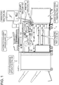
- Fig. 1 is a central sectional view of the whole of the image forming apparatus that shows a mechanical structure. Its structure will be explained as follows.
- scanner section 130 including CCD 131 and automatic document feeder (ADF) 135 so that images of a document may be read.
- operation section 140 composed of a touch panel is provided at a position where a platen glass is not positioned on the upper portion of image forming apparatus 1, so that an operator may operate and information may be displayed.
- the operation section 140 is one that corresponds to a display section, an inputting section and a display device of the invention.
- paper feeding trays (1-3) 160 there are arranged plural paper feeding trays (1-3) 160 (3 steps in the drawing), and further, large capacity paper feeding tray 161 is arranged to be an annex to the image forming apparatus 1 to serve as a paper of feeding tray in the same way.
- printer section 150 that is composed of LD section 152, photoconductor 153, charging unit 154, developing unit 155, transfer section 156, and of fixing unit 157, and the printer section 150 corresponds to an image forming section of the invention, and it executes image data obtained from scanner section 130 and executes reserve JOB for forming an image on a sheet based on the established image forming conditions.
- the charging unit 154, the developing unit 155 and the transfer section 156 are arranged around the photoconductor 153.
- the charging unit 154 charges a surface of the photoconductor 153 evenly before image writing.
- the LD section 152 forms an electrostatic latent image on the photoconductor 153 by irradiating a semiconductor laser on the photoconductor 153 whose surface is charged evenly.
- the developing unit 155 develops the electrostatic latent image formed on the photoconductor 153 by the LD section 152, with toner member. A toner image is formed on the photoconductor 153 by this development processing.
- the transfer section 156 transfers the toner image existing on the photoconductor 153 onto a sheet that is conveyed from the paper feeding tray (1-3) 160 or from large capacity paper feeding tray 161. A sheet onto which a toner image has been transferred is separated from the photoconductor 153 and is conveyed to the fixing unit 157. Toner member remaining on the photoconductor 153 is removed by a cleaning section.
- the toner image that has been transferred onto the surface side of the sheet is fixed when the sheet conveyed to the fixing unit 157 is heated.
- the sheet that has undergone fixing processing is conveyed to post-processing apparatus (FNS) 180 as it is, in the case of single-sided printing.
- FNS post-processing apparatus
- stapling, punching and cutting are carried out.
- the sheet after its fixing processing undergoes switchback, and a prescribed image is transferred on the reverse side of the sheet in the printer section 150.
- the sheet having images on its both sides is conveyed to the post-processing apparatus (FNS) 180 after fixing processing.
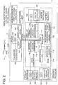
- Fig. 2 is a diagram showing a circuit block of image forming apparatus 1 representing a digital multifunctional peripheral (a copier, a printer and a scanner), and its contents are explained in detail as follows.
- the image forming apparatus 1 is equipped with a digital copier body having therein control block 110, scanner section 130, operation section 140 and printer section 150 and with image processing device 160 that processes image data inputted from external equipment such as terminal 3 through LAN 4, or makes it possible to transfer image data obtained through scanner section 130 to external equipment such as terminal 3 through LAN 4.
- the control block 110 has PCI bus 112 connected to the aforesaid image processing device 160, and DRAM control IC 111 is connected to the aforesaid PCI bus 112.
- An image memory composed of compression memory 120 and of page memory 121 is connected to DRAM control IC 111.
- the compression memory 120 is a memory to store compression image data such as JOB schedule screen and a document
- the page memory 121 is a memory for storing temporarily non-compression image data to be printed before image forming.
- HDD 127 connected to PCI bus 112 preserves JOB or the like generated by terminal 3 that is connected to image forming apparatus 1 or to image processing device 160.
- HDD 127 there are preserved a plurality of JOBs.
- information of the whole of JOB information of each page unit and image data.
- JOB setting information there are included, for example, information of identification number of JOB and of tray to be used and information of sheet sizes.
- control block 110 is equipped with image control CPU 113, and the aforesaid DRAM control IC 111 is connected to the image control CPU 113.
- the image control CPU 113 is connected to ROM 114 and to nonvolatile memory 115.
- the nonvolatile memory 115 there are stored establishment data including initial printing establishment information of image forming apparatus 1, machine establishment information such as process control parameter, user established values, and sheet information of each paper feeding tray (sheet size and sheet type) and control information of reserve JOB, while, in ROM 114, there are stored programs to operate the aforesaid image control CPU 113 and others.
- the image control CPU 113 is capable of reading the aforesaid ROM 114 and nonvolatile data of nonvolatile memory 115, and is capable of writing desired data on nonvolatile memory 115 as nonvolatile data.
- the image control CPU 113 controls operations of respective sections of the image forming apparatus 1 based on the aforesaid machine establishment information, print establishment information and JOB control information.
- the image control CPU 113 is one to control the whole of the image forming apparatus 1, and it corresponds to the control section of the invention.
- the image control CPU 113 conducts management and control for a reservation and execution of JOBs stored in HDD 127 and in compression memory 120.
- the aforesaid scanner 130 is equipped with CCD 131 that conducts optical reading and with scanner control section 132 that conducts controlling of the whole of the scanner 130.
- the scanner control section 132 is connected to the aforesaid image control CPU 113 to be capable of conducting serial communication.
- the aforesaid CCD 131 is connected to reading processing section 116 that processes image data obtained through reading by the CCD 131, and compression IC 118 that conducts compression processing for image data is connected to the reading processing section 116, and the compression IC 118 is connected to the aforesaid DRAM control IC 111.
- the aforesaid operation section 140 is equipped with LCD 141 that serves as a display section and an input section and is composed of a touch panel and with operation section controller 142 that controls the whole of an operation section, and the operation section controller 142 is connected to the aforesaid image control CPU 113 to be capable of conducting serial communication.
- control by the image control CPU 113 is received, and setting input concerning mechanical setting input and output such as print setting and operation control conditions in image forming apparatus 1, a display of contents of setting and a display of desired information such as a schedule screen are made to be possible by LCD 141.
- setting (of sizes and types of sheets) for sheet information for each paper feeding tray, and setting of output mode for example, ordinary copy mode and confirmation copy mode) are made to be possible.
- extension IC 125 that extends compressed image data is connected to the aforesaid DRAM control IC 111, and writing processing section 126 is connected to the extension IC 125.
- the writing processing section 126 is connected to LD section (laser diode) 152 of printer section 150, and conducts processing of writing data used for operations of the LD section 152.
- the printer section 150 is equipped with printer controller 151 that controls all (paper feeding, image forming, sheet ejection and post-processing) of printer section 150, and the printer controller 151 is connected to the aforesaid image control CPU 113.
- the printer controller 151 operates, following the control instructions of the image control CPU 113, to control the printer section 150.
- DRAM control IC 161 of the image processing device 160 is connected to PCI bus 112 to which the DRAM control IC 111 is connected.
- the image processing device 160 is one to receive image data in image forming apparatus 1 from terminal 3 connected to LAN 4, or to transmit image data obtained by scanner section 130 to terminal 3 connected to LAN 4, when an image forming apparatus is used as a network printer or a network scanner.
- image memory 162 composed of DRAM is connected to DRAM control IC 161.
- controller control CPU 163 that controls the whole of image processing device 160, LAN interface 165 and HDD 166 are connected to the common bus.
- the LAN interface 165 is connected to LAN 4.
- the image control CPU 113 operates in accordance with programs, and it issues instructions to scanner section 130 based on operations by operation section 140. Images obtained through reading by CCD 131 undergo data processing in reading processing section 116, and image data having undergone data processing are compressed by a prescribed method in compression IC 118, to be stored in compression memory 120 or in HDD 127 through DRAM control IC 111.
- the image data are inputted in image forming apparatus 1 through LAN 4.
- image processing device 160 through LAN 4 or LAN interface 165, and are stored temporarily in image memory 162 or HDD 166 by DRAM control IC 161.
- Data of the aforesaid image memory 162 or HDD 166 are forwarded to DRAM control IC 111 through PCI bus 112, and are stored temporarily in page memory 121.
- Data stored in page memory 121 are conveyed to compression IC 1118 in order through DRAM control IC 111, and are compressed, and are stored in compression memory 120 or HDD 127 through DRAM control IC 111.
- image data stored in compression memory 120 or in HDD 127 in the aforesaid way are sent out to extension IC 125 through DRAM control IC 111, and the data are extended.
- the extended data are sent out to writing processing section 126 through DRAM control IC 111, to generate writing data, thus, writing on photoconductor 153, is conducted in LD section 152.
- printer controller 151 that has received instructions of image control CPU 113 controls respective portions such as paper feeding trays (1 -3) 160, large capacity paper feeding tray 161 and conveyance paths.
- image forming, transfer onto a sheet, fixing, conveyance to post-processing apparatus (FNS) 180 through a conveyance path and post-processing in the post-processing apparatus (FNS) 180 are conducted in order, and printing output is carried out.
- sheet information for each paper-feeding tray is established in advance through operation section 140, and is stored in nonvolatile memory 115.
- Image control CPU 113 reads out data stored in the aforesaid nonvolatile memory 115 for execution of each JOB, and then, selects a paper feeding tray needed for JOB, and conducts paper feeding. When there are reserve JOBs, respective JOBs are executed in order in accordance with established order.
- selection is one including a selection decided by touching of a screen and a selection decided by cursor operations.
- image control CPU 113 The following display control is carried out by image control CPU 113.
- a menu image which is not illustrated as an initial screen is displayed on operation section 140.
- On the upper portion of the menu screen there are displayed mechanical state button 301, JOB list button 302, reading out button 303, copy button 304 and scan button 305.
- JOB list button 302 for example, is selected, in this case, JOB control screen is displayed.
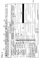
- Fig. 3 shows only a background section of a JOB control screen.
- JOB schedule screen 300 is displayed on operation section 140, as shown in Fig. 3 .
- the JOB schedule screen 300 is a screen for causing a user to be capable of estimating user actions such as paper feeding and replacement in advance, by informing the user visually of remaining time for each JOB, a tray to be used, a remaining amount of sheets and machine stop timing.
- On the vertical axis of the JOB schedule screen 300 there is arranged information of connected trays, and on the transversal axis, there is arranged time information.
- tray information such as sheet tray of the image forming apparatus 1 and tray information of post-processing apparatus to be connected to the image forming apparatus 1, in order, beginning from the upper side on the left of the JOB schedule screen 300.
- tray information such as "infinite form” is displayed in “Tray 1”
- tray information such as "B4 (landscape) plain paper” is displayed in “Tray 2”
- tray information such as "A4 (portrait) plain paper” is displayed in "Tray 3”. Owing to these tray information, it is possible to recognize reserved JOB that uses plural trays and to recognize tray information of JOB including JOB that is in the course of outputting prints.
- the numerical value corresponding to the established display scale is displayed so that time required for each JOB may be recognized visually.
- numerals such as 0, 10, 20 and 30 are displayed as shown in Fig. 3 .
- a zoom button for changing a display scale.
- the zoom button is composed of contracting button 320 to contract the display scale and of expanding button 322 to expand the display scale.
- a user can switch the display scale freely by conducting selecting operations for the contracting button 320 or the expanding button 322.
- a range of switching for the display scale can be established by the 23 steps, for example, from the minimum 30 minutes to the maximum 24 hours.
- time information corresponding to the display scale of the JOB schedule screen 300 is stored in nonvolatile memory 115, each time the display schedule unit is switched. For example, in the case of turning on of the power supply, or in the case of transition of modes, or in the case of transition of screen from other screens, time information stored in nonvolatile memory 115 is read out, and a numerical value on the time axis of JOB schedule screen 300 is displayed based on the time information.
- JOB schedule screen 300 reserve JOB and a JOB in the course of outputting (execution) are displayed by JOB bar (JOB image) JB based on a tray to be used, an order of execution of JOB and on remaining time.
- JOB bars including JB1 - JB10 corresponding to 10 reserve JOBs are displayed on JOB schedule screen 300, and JOBs are displayed along the direction of time axis beginning from the left end on the screen in the order wherein the earliest order for execution of JOB comes first.
- JOB bars JB are displayed in different colors through classification by colors for the purpose of indicating remaining number of sheets in connected trays. Meanwhile, in the drawing, blue JOB bar JB is shown by shaded area and red JOB bar JB is shown to be black area, for convenience sake. In the drawings, shaded JOB bar JB shows that sufficient sheets are stored in a sheet tray and printing is possible accordingly. Further, black JOB bars JB (JB 3 and JB 10 in the present drawing) show that no sheet is in a sheet tray, or, print output is stopped on the half way because of shortage of sheets, because of a wrong sheet.
- the state of sheet tray can be recognized visually by the user, thus, it is possible for the user to know necessity of sheet replenishment and to conduct changes of setting for paper feeding tray in advance.
- the black JOB bar is one to show warning.
- JOB bars JB 2 - 6 for tray 2 it is displayed that 5 JOBs are continued by JOB bars JB 2 - 6 for tray 2, and JOB bar JB 3 that is one of them is displayed to be in a black color that shows warning.
- JOB bars are divided into two colors in the classification by colors in this example, it may also be possible to be divided into three or more colors.
- JOB bar JB among plural JOB bars JB displayed on JOB schedule screen When specific JOB bar JB among plural JOB bars JB displayed on JOB schedule screen is pressed down by a touching operation or a cursor operation, a pop-up screen corresponding to the selected JOB bar JB is displayed on the upper portion or the lower portion of JOB bar JB. On the pop-up screen, there are displayed detailed information in each JOB, such as, for example, a file name of the selected JOB bar JB, a sheet size, a sheet type and sheet basis weight.
- a length of the aforesaid JOB bar is also changed based on the changed display schedule.
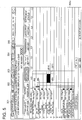
- Fig. 4 is a diagram wherein a scale of 30 minutes in Fig. 3 was changed to a scale of 4 hours, and it is a display screen displayed by a display method in prior art.
- On the transversal axis showing time of JOB schedule screen 300a there are displayed numerical values 0, 0.5, 1.0, 1.5 ... 3.0, 3.5 and 4.0 as shown in Fig. 4 .
- JOB bar JB 11 which has not been displayed on the scale of 30 minutes is displayed on schedule screen 300a.
- the two JOB bars JB are displayed on the same display area to be overlapped.
- the same display area mentioned in this case is an area for displaying continuous JOB bars each having become the minimum display unit or smaller than that, and it can be set by a user optionally.
- the minimum display unit is set to 1 pixel (time axis)
- JOB bars JB 2 - JB 6 are overlapped. Owing to this, the whole of black JOB bar JB 3 becomes to be in the state of being displayed in the lower layer, which makes a user to be difficult to recognize warning.
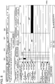
- Fig. 5 is one to show JOB schedule screen 300b that is displayed by the display method of the invention, when the aforesaid scale in Fig. 3 is changed in the same way as in Fig. 4 .
- information that should be recognized by a user namely, information showing warning in the present example (JOB bar JB 3) is displayed to be black in the uppermost layer in priority to other JOB bars. Due to this, a user can recognize easily the information showing warning.
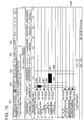
- JOB schedule screen 300b when JOB bar JB 3 displayed in the uppermost layer through overlapping is selected and operated through touching operations, pop-up screen 400 is displayed as is shown in JOB schedule screen 300c in Fig. 6 .
- JOB setting information 410 including a file name of the selected JOB bar JB, a sheet size, a sheet type and a sheet basis weight, as well as button 411 for paper setting change. Owing to this, it is possible for an operator to carry out processing for dissolving contents of warning promptly, and to reduce downtime of an image forming apparatus as far as possible.
- the procedures by image control CPU 113 are started.
- the image control CPU 113 draws a background section other than JOB bar JB that constitutes JOB schedule screen.
- the background section includes numerical values corresponding to a sheet size and a display scale which are displayed on connected tray, contracting button 320 and expanding button 322.
- step S1 image control CPU 113 reads out and obtains execution order for each JOB, trays to be used, and JOB setting information for execution time. For example, in the case of JOB 5, image control CPU 113 obtains information such as execution order of JOB "No. 5", tray to be used "Tray 2" and execution time "1 minute 40 seconds". After that, the flow moves to step s2.
- step S2 image control CPU 113 converts execution time of each JOB obtained to the display size corresponding to display scale. In other words, the image control CPU 113 calculates a length in the direction of time axis for JOB bar JB corresponding to each JOB, from the established display scale and from execution time of JOB.
- step S3 the image control CPU 113 adds up execution times for all previous JOBs preceding its own JOB, and it calculates execution clock time of its own JOB (JOB starting clock time). For example, in the case of JOB 5, an execution clock time for its own JOB 5 is calculated by adding up execution times for JOB 1 - JOB 4.
- step S4 the image control CPU 113 calculates image drawing positions in JOB schedule screen for each JOB, based on JOB setting information such as execution order of each JOB, a tray to be used, execution time and execution clock time all acquired from HDD 127, and it prepares drawing images in the order of execution clock time.
- step S5 it is judged whether the image drawing position thus prepared is overlapped with that of previous JOB or not.
- stepS5 When the prepared image drawing position is judged not to be overlapped with previous JOB (stepS5, NO), information of objective JOB is drawn on JOB schedule screen 300 (step S6). Image drawing of the aforesaid JOB is continued in the order of clock time until the moment when image drawings for all JOBs are completed (stepS8).
- step S5 a position of image drawing for the JOB that becomes objective in the aforesaid step S5 is overlapped with that of the previous JOB
- step S7 the previous JOB is judged whether it is warning display or not.
- information of JOB displayed to be in black as mentioned above corresponds to warning display.
- image drawing is conducted for the objective JOB (step S6).
- JOB information is displayed to be overlapped, but the warning display is not included in the overlapped portion.
- Image drawings for respective JOBs are continued in the order of clock time until the moment when image drawings for all JOBs are completed (step s8).
- step S7 when the previous JOB is warning display (step S7, YES), a flow moves to the image drawing processing of the succeeding JOB (from step S8 to step s4) without conducting image drawing for the objective JOB. Due to this, with respect to JOB information for warning display, information of following JOB is not displayed to be overlapped, and warning display is indicated on the uppermost layer constantly.
- processing is terminated (step S8, YES).
- JOB bars JB 1 - JB 7 are displayed with display scale of 30 minutes in the same way as in Fig. 3 .
- the JOB bars JB 2 and JB 7 are displayed to be in black, and other JOB bars are displayed through halftone, and JOB bars JB 2 and JB 7 are those to display warning.
- a display scale of the aforesaid JOB schedule screen 300d is changed, and those displayed by display scale of 4 hours through a traditional display method are JOB schedule screen 300e shown in Fig. 9 .
- JOB bar JB 8 which was not displayed through the scale of 30 minutes is displayed newly.
- each JOB bar is not changed to be in the same change of the scale, but each JOB bar is displayed in a size that is larger than an original scale change.
- the JOB bar is displayed to be extended in terms of a length in the direction toward the front and the direction toward the rear, in the direction of time axis.
- JOB schedule screen 300d in Fig. 8 before the scale change JOB bar JB 2 is displayed remarkably to be in black as a warning display.
- JOB schedule screen 300f shown in Fig. 10 is one in which JOB bar JB2 is displayed on the uppermost layer.
- the JOB bar JB2 is displayed to be larger than its original size of display scale, thus, it is more easy for a user to recognize visually, and operations for selection can be conducted easily.
- each JOB bar is displayed to be larger in terms of a size than an actual display scale in the aforesaid situation
- a method wherein each JOB bar is changed in terms of a shape to serve as a mark so that visual confirmation may become easy, and in this case again, visual recognition and selection operations become easy, by displaying JOB bar for warning display in the uppermost layer.
- the invention makes it possible for a user to confirm visually the information by controlling display so that the information that should be recognized by the user may be displayed on the uppermost layer.
- the display section has only to be one that can display the aforesaid information, and CRT, a liquid crystal display and an organic EL can be used. Further, it is possible to constitute a display section with a touch panel that serves also as an inputting section. On the touch panel, it is possible to conduct detection for the display panel section and for a coordinate position corresponding to a button position for the display panel. Further, an inputting portion may also be one composed of a mouse and a cursor key, in addition to the foregoing. In a word, the inputting portion has only to be one that can select the information of JOB displayed on a schedule screen.
- the aforesaid display conditions there are given display scales on the schedule screen. For example, in some display scales, it is necessary to display a part or the whole of the information to be overlapped, when it is difficult to display information concerning the aforesaid two or more JOBs on a thorough noninterference basis.
- this overlapped display when the information that should be recognized by a user, such as the information of warning becomes to be invisible utterly, or when the aforesaid information is invisible except only an extremely a part of the information, visual confirmation by a user becomes difficult. Therefore, when this information is displayed on the uppermost layer, visibility by a user becomes possible.
- Display on the uppermost layer may either be one where all of display areas concerning the information are displayed or be one wherein recognition and selection operations for a user are made to be easy by enlarging its area to the minimum unit or more, though only a part of display area of information is displayed, and the entire portion of information area is not covered when the display area of the information is limited to a part to be less than a minimum unit.
- Information relating to JOB can be displayed by character information or by functional buttons, and selecting operations for the information can be carried out by an input section such as a touch panel or a mouse. Further, for the information displayed on the uppermost layer, it is possible to make selecting operations for the aforesaid information to be possible equally. After the selecting operations have been conducted, processing established in advance is carried out. For example, it is possible to indicate a display related to the aforesaid JOB on the uppermost layer through a pop-up screen. When the information which should be recognized by a user is a warning, it is possible to conduct detailed display of the warning as a display related to the JOB.
- the present invention makes it possible for a user to recognize surely the information that should be recognized by the user such as warning information by displaying the aforesaid information on the uppermost layer, even in the case where plural pieces of information are in existence in the same position within the schedule screen. Further, if information items displayed on the uppermost layer are made to be possible for selecting operations, there is an effect to make it possible to operate target buttons including warning information preferentially.
Description
- The present invention relates to a display method that displays a schedule screen showing an execution reservation state of JOB on a display section of an image forming apparatus, a display device and an image forming apparatus.
- With respect to sizes of various buttons which are displayed on a display section that is provided on an image forming apparatus and represent an object of operation by a user, they are usually determined by taking operations on a touch panel and operations on a mouse into account. On the display screen that displays an execution reservation state for plural JOBs, for example, on the JOB list screen, information concerning plural JOBs, is displayed on the screen in accordance of the aforesaid schedule.
- However, for the object whose size and position cannot be determined only one-sidedly, it is impossible to take the configuration mentioned above. For example, in the case of the screen structure showing reserved JOB at a size corresponding to its time scale, JOB itself sometimes disappears from the screen if the scale on the horizontal axis is switched to a larger unit.
- Therefore, when plural screens need to be displayed on a display section, there has been suggested a mode wherein plural screens are drawn to be superimposed, and an operation system to turn over a window for displaying contents existing on the lower layer of the displayed contents which have been drawn to be superimposed, is provided, so that information may be displayed through user operations (see Unexamined Japanese Patent Application Publication No.
6-242916 - However, when JOBs each requiring writing to be superimposed are in existence continuously, there occurs unfortunately a state wherein plural JOBs exist in a size shown by one dot representing a minimum unit on a screen, and in particular, JOB that is different from ordinary state exists to obstruct a user to know the existence of the information on its screen, even when information to be recognized by the user such as warning exists. Therefore, even in the case where information for warning exists in a lower layer, it is difficult to arrive at a moment to display the aforesaid information by the aforesaid operation of turning over the window. In this case, a user can view each JOB, and it is necessary for the user to switch the scale to the selectable size.
-
EP-A- 1473661 describes a printing system and method in which printing jobs and their schedules are displayed in a window on a display unit. The printing jobs are displayed in a matrix form. Paper types are listed in a column with a second display showing what jobs are planned for the next predetermined period of time. In this way the jobs and the paper types together form a matrix. The matrix is set out to indicate a time line for specific jobs and what types of paper are being used. Where a specific job may be compromised because there is no paper, for this specific job, then a block is highlighted to show to an operator that action needs to be taken. -
US2002057455 describes a printing system wherein print-jobs are displayed in the schedule view with rectangular shapes having lengths corresponding to printing time and colour (or pattern) corresponding to its state, and the print-jobs are arranged and displayed in the order of prints to which the print-jobs are allocated. It is possible to intuitively grasp relative magnitude of a load of each printer by the length of a job graph, and an absolute amount of the load of each printer converted into a printing time by a displayed time scale. In addition to this, details of a job which is being processed, details of a selected job, and a state of each printer are also displayed. -
US2005243365 ,US2006197977 andUS2006044594 describe a device for scheduling and controlling print jobs in a printing device. The print jobs and their schedule can be displayed in a graphical user interface which graphically represents the print jobs and their schedules. - The present invention has been achieved in view of the aforesaid problems, and in the invention, when a unit of the display scale is not appropriate as stated above, and when plural pieces of JOB information exist on the same position, those pieces of information are displayed to be superimposed, and when JOB whose state is different from ordinary state is in existence, a user can recognize existence of the JOB without requiring operations such as scale changes, by displaying the JOB on the uppermost layer, and an improvement of operability can be aimed, by making selection operations concerning the aforesaid JOB to be possible by request.
- In a first aspect of the present invention, there is provided display method according to
claim 1. - In a second aspect there is provided a display device in accordance with
claim 8. - In a third aspect of the invention, there is provided an image forming apparatus according to claim 17.
- These and other objects, advantages and features of the invention will become apparent from the following description thereof taken in conjunction with the accompanying drawings in which:
-
Fig. 1 is a diagram showing an example of a structure of an image forming apparatus relating to an embodiment of the invention; -
Fig. 2 is a diagram showing an example of a block structure of an image forming apparatus relating to an embodiment of the invention; -
Fig. 3 is a diagram showing an example of a structure of the schedule screen relating to an embodiment of the invention; -
Fig. 4 is a diagram showing an example of the schedule screen displayed by the conventional display method when the display scale is changed, relating to an embodiment of the invention; -
Fig. 5 is a diagram showing an example of the schedule screen displayed by the display method of the invention when the display scale is changed, relating to an embodiment of the invention; -
Fig. 6 is a diagram showing an example of a structure of the schedule screen when warning display is selected and operated, relating to an embodiment of the invention; -
Fig. 7 is a flow chart showing procedures of a display method for schedule screen, relating to an embodiment of the invention; -
Fig. 8 is a diagram showing another example of a structure of the schedule screen, relating to an embodiment of the invention; -
Fig. 9 is a diagram showing an example of a structure of the schedule screen displayed by the conventional display method when the display scale is changed, relating to an embodiment of the invention; and -
Fig. 10 is a diagram showing another example of a structure of the schedule screen displayed by the display method of the invention when the display scale is changed, relating to an embodiment of the invention. - An embodiment of the invention will be explained as follows, based on attached drawings.
Fig. 1 is a central sectional view of the whole of the image forming apparatus that shows a mechanical structure. Its structure will be explained as follows. - On the upper portion of
image forming apparatus 1, there are providedscanner section 130 includingCCD 131 and automatic document feeder (ADF) 135 so that images of a document may be read. Further,operation section 140 composed of a touch panel is provided at a position where a platen glass is not positioned on the upper portion ofimage forming apparatus 1, so that an operator may operate and information may be displayed. Theoperation section 140 is one that corresponds to a display section, an inputting section and a display device of the invention. - Further, on the lower portion of the
image forming apparatus 1, there are arranged plural paper feeding trays (1-3) 160 (3 steps in the drawing), and further, large capacitypaper feeding tray 161 is arranged to be an annex to theimage forming apparatus 1 to serve as a paper of feeding tray in the same way. Inside the main body of the image forming apparatus, there is provided a conveyance path through which a sheet that is fed from the paper feeding tray is conveyed, and there is providedprinter section 150 that is composed ofLD section 152,photoconductor 153,charging unit 154, developingunit 155,transfer section 156, and offixing unit 157, and theprinter section 150 corresponds to an image forming section of the invention, and it executes image data obtained fromscanner section 130 and executes reserve JOB for forming an image on a sheet based on the established image forming conditions. - The
charging unit 154, the developingunit 155 and thetransfer section 156 are arranged around thephotoconductor 153. Thecharging unit 154 charges a surface of thephotoconductor 153 evenly before image writing. TheLD section 152 forms an electrostatic latent image on thephotoconductor 153 by irradiating a semiconductor laser on thephotoconductor 153 whose surface is charged evenly. The developingunit 155 develops the electrostatic latent image formed on thephotoconductor 153 by theLD section 152, with toner member. A toner image is formed on thephotoconductor 153 by this development processing. Thetransfer section 156 transfers the toner image existing on thephotoconductor 153 onto a sheet that is conveyed from the paper feeding tray (1-3) 160 or from large capacitypaper feeding tray 161. A sheet onto which a toner image has been transferred is separated from thephotoconductor 153 and is conveyed to thefixing unit 157. Toner member remaining on thephotoconductor 153 is removed by a cleaning section. - In the
fixing unit 157, the toner image that has been transferred onto the surface side of the sheet is fixed when the sheet conveyed to thefixing unit 157 is heated. The sheet that has undergone fixing processing is conveyed to post-processing apparatus (FNS) 180 as it is, in the case of single-sided printing. In the post processing apparatus (FNS) 180, stapling, punching and cutting are carried out. On the other hand, in the case of two-sided printing, the sheet after its fixing processing undergoes switchback, and a prescribed image is transferred on the reverse side of the sheet in theprinter section 150. Thus, the sheet having images on its both sides is conveyed to the post-processing apparatus (FNS) 180 after fixing processing. -
Fig. 2 is a diagram showing a circuit block ofimage forming apparatus 1 representing a digital multifunctional peripheral (a copier, a printer and a scanner), and its contents are explained in detail as follows. - The
image forming apparatus 1 is equipped with a digital copier body having thereincontrol block 110,scanner section 130,operation section 140 andprinter section 150 and withimage processing device 160 that processes image data inputted from external equipment such asterminal 3 throughLAN 4, or makes it possible to transfer image data obtained throughscanner section 130 to external equipment such asterminal 3 throughLAN 4. - The
control block 110 hasPCI bus 112 connected to the aforesaidimage processing device 160, and DRAM control IC 111 is connected to theaforesaid PCI bus 112. An image memory composed ofcompression memory 120 and ofpage memory 121 is connected to DRAM control IC 111. Thecompression memory 120 is a memory to store compression image data such as JOB schedule screen and a document, and thepage memory 121 is a memory for storing temporarily non-compression image data to be printed before image forming. - Further,
HDD 127 connected toPCI bus 112 preserves JOB or the like generated byterminal 3 that is connected to image formingapparatus 1 or toimage processing device 160. InHDD 127, there are preserved a plurality of JOBs. In each JOB, there are included information of the whole of JOB, information of each page unit and image data. In the information of the whole of JOB (hereinafter referred to as JOB setting information), there are included, for example, information of identification number of JOB and of tray to be used and information of sheet sizes. - Further,
control block 110 is equipped withimage control CPU 113, and the aforesaid DRAM control IC 111 is connected to theimage control CPU 113. - In addition, the
image control CPU 113 is connected toROM 114 and tononvolatile memory 115. In thenonvolatile memory 115, there are stored establishment data including initial printing establishment information ofimage forming apparatus 1, machine establishment information such as process control parameter, user established values, and sheet information of each paper feeding tray (sheet size and sheet type) and control information of reserve JOB, while, inROM 114, there are stored programs to operate the aforesaidimage control CPU 113 and others. - The
image control CPU 113 is capable of reading theaforesaid ROM 114 and nonvolatile data ofnonvolatile memory 115, and is capable of writing desired data onnonvolatile memory 115 as nonvolatile data. Theimage control CPU 113 controls operations of respective sections of theimage forming apparatus 1 based on the aforesaid machine establishment information, print establishment information and JOB control information. Theimage control CPU 113 is one to control the whole of theimage forming apparatus 1, and it corresponds to the control section of the invention. Theimage control CPU 113 conducts management and control for a reservation and execution of JOBs stored inHDD 127 and incompression memory 120. - Next, the
aforesaid scanner 130 is equipped withCCD 131 that conducts optical reading and withscanner control section 132 that conducts controlling of the whole of thescanner 130. Thescanner control section 132 is connected to the aforesaidimage control CPU 113 to be capable of conducting serial communication. Further, theaforesaid CCD 131 is connected to readingprocessing section 116 that processes image data obtained through reading by theCCD 131, andcompression IC 118 that conducts compression processing for image data is connected to thereading processing section 116, and thecompression IC 118 is connected to the aforesaid DRAM control IC 111. - The
aforesaid operation section 140 is equipped withLCD 141 that serves as a display section and an input section and is composed of a touch panel and withoperation section controller 142 that controls the whole of an operation section, and theoperation section controller 142 is connected to the aforesaidimage control CPU 113 to be capable of conducting serial communication. In theoperation section 140, control by theimage control CPU 113 is received, and setting input concerning mechanical setting input and output such as print setting and operation control conditions inimage forming apparatus 1, a display of contents of setting and a display of desired information such as a schedule screen are made to be possible byLCD 141. In addition, setting (of sizes and types of sheets) for sheet information for each paper feeding tray, and setting of output mode (for example, ordinary copy mode and confirmation copy mode) are made to be possible. - Further,
extension IC 125 that extends compressed image data is connected to the aforesaid DRAM control IC 111, and writingprocessing section 126 is connected to theextension IC 125. Thewriting processing section 126 is connected to LD section (laser diode) 152 ofprinter section 150, and conducts processing of writing data used for operations of theLD section 152. Further, theprinter section 150 is equipped withprinter controller 151 that controls all (paper feeding, image forming, sheet ejection and post-processing) ofprinter section 150, and theprinter controller 151 is connected to the aforesaidimage control CPU 113. Theprinter controller 151 operates, following the control instructions of theimage control CPU 113, to control theprinter section 150. - Further,
DRAM control IC 161 of theimage processing device 160 is connected toPCI bus 112 to which the DRAM control IC 111 is connected. Theimage processing device 160 is one to receive image data inimage forming apparatus 1 fromterminal 3 connected toLAN 4, or to transmit image data obtained byscanner section 130 toterminal 3 connected toLAN 4, when an image forming apparatus is used as a network printer or a network scanner. In theimage processing device 160,image memory 162 composed of DRAM is connected toDRAM control IC 161. Further, in theimage processing device 160, the aforesaidDRAM control IC 161,controller control CPU 163 that controls the whole ofimage processing device 160,LAN interface 165 andHDD 166 are connected to the common bus. TheLAN interface 165 is connected toLAN 4. - Next, basic operations of the aforesaid
image forming apparatus 1 will be explained. - First, procedures to accumulate image data in the
image forming apparatus 1 will be explained. - First, an occasion to read images with
scanner section 130 and to generate image data, in theimage forming apparatus 1, will be explained. In thescanner section 130, images are read from a document byCCD 131 optically. In this case, operations ofCCD 131 are controlled byscanner section controller 132 that receives instructions from theimage control CPU 113. Reading of a document may either be conducted by automatic document feeder (ADF) 135 or be conducted by placing a document on a platen glass. - The
image control CPU 113 operates in accordance with programs, and it issues instructions toscanner section 130 based on operations byoperation section 140. Images obtained through reading byCCD 131 undergo data processing inreading processing section 116, and image data having undergone data processing are compressed by a prescribed method incompression IC 118, to be stored incompression memory 120 or inHDD 127 through DRAM control IC 111. - In addition, the image data are inputted in
image forming apparatus 1 throughLAN 4. As the aforesaid image data, there are given those generated by application programs such asterminal 3, for example, and those generated by another image forming apparatus. The aforesaid data are received byimage processing device 160 throughLAN 4 orLAN interface 165, and are stored temporarily inimage memory 162 orHDD 166 byDRAM control IC 161. Data of theaforesaid image memory 162 orHDD 166 are forwarded to DRAM control IC 111 throughPCI bus 112, and are stored temporarily inpage memory 121. Data stored inpage memory 121 are conveyed to compression IC 1118 in order through DRAM control IC 111, and are compressed, and are stored incompression memory 120 orHDD 127 through DRAM control IC 111. - When conducting image output in the
image forming apparatus 1, image data stored incompression memory 120 or inHDD 127 in the aforesaid way are sent out toextension IC 125 through DRAM control IC 111, and the data are extended. The extended data are sent out to writingprocessing section 126 through DRAM control IC 111, to generate writing data, thus, writing onphotoconductor 153, is conducted inLD section 152. Further, inprinter section 150,printer controller 151 that has received instructions ofimage control CPU 113 controls respective portions such as paper feeding trays (1 -3) 160, large capacitypaper feeding tray 161 and conveyance paths. In theprinter section 150, image forming, transfer onto a sheet, fixing, conveyance to post-processing apparatus (FNS) 180 through a conveyance path and post-processing in the post-processing apparatus (FNS) 180 are conducted in order, and printing output is carried out. Incidentally, sheet information for each paper-feeding tray is established in advance throughoperation section 140, and is stored innonvolatile memory 115.Image control CPU 113 reads out data stored in the aforesaidnonvolatile memory 115 for execution of each JOB, and then, selects a paper feeding tray needed for JOB, and conducts paper feeding. When there are reserve JOBs, respective JOBs are executed in order in accordance with established order. - Next, an example of a structure of
JOB schedule screen 300 will be explained. Meanwhile, in the present example, "selection" is one including a selection decided by touching of a screen and a selection decided by cursor operations. The following display control is carried out byimage control CPU 113. - When a power supply for the
image forming apparatus 1 is turned on, a menu image which is not illustrated as an initial screen is displayed onoperation section 140. On the upper portion of the menu screen, there are displayedmechanical state button 301,JOB list button 302, reading outbutton 303,copy button 304 andscan button 305. When theJOB list button 302, for example, is selected, in this case, JOB control screen is displayed. Incidentally,Fig. 3 shows only a background section of a JOB control screen. - When an unillustrated scheduling button, for example, is selected on the JOB control screen,
JOB schedule screen 300 is displayed onoperation section 140, as shown inFig. 3 . - The
JOB schedule screen 300 is a screen for causing a user to be capable of estimating user actions such as paper feeding and replacement in advance, by informing the user visually of remaining time for each JOB, a tray to be used, a remaining amount of sheets and machine stop timing. On the vertical axis of theJOB schedule screen 300, there is arranged information of connected trays, and on the transversal axis, there is arranged time information. - On the vertical axis showing a connected tray in the
JOB schedule screen 300, there are displayed tray information such as sheet tray of theimage forming apparatus 1 and tray information of post-processing apparatus to be connected to theimage forming apparatus 1, in order, beginning from the upper side on the left of theJOB schedule screen 300. For example, tray information such as "infinite form" is displayed in "Tray 1", then, tray information such as "B4 (landscape) plain paper" is displayed in "Tray 2", and tray information such as "A4 (portrait) plain paper" is displayed in "Tray 3". Owing to these tray information, it is possible to recognize reserved JOB that uses plural trays and to recognize tray information of JOB including JOB that is in the course of outputting prints. - On the transversal axis showing time of the
JOB schedule screen 300, the numerical value corresponding to the established display scale is displayed so that time required for each JOB may be recognized visually. For example, in the case of the display scale of 30 minutes, numerals such as 0, 10, 20 and 30 are displayed as shown inFig. 3 . At the center in the lower portion of theJOB schedule screen 300, there is displayed a zoom button for changing a display scale. The zoom button is composed ofcontracting button 320 to contract the display scale and of expandingbutton 322 to expand the display scale. A user can switch the display scale freely by conducting selecting operations for thecontracting button 320 or the expandingbutton 322. A range of switching for the display scale can be established by the 23 steps, for example, from the minimum 30 minutes to the maximum 24 hours. - Further, time information corresponding to the display scale of the
JOB schedule screen 300 is stored innonvolatile memory 115, each time the display schedule unit is switched. For example, in the case of turning on of the power supply, or in the case of transition of modes, or in the case of transition of screen from other screens, time information stored innonvolatile memory 115 is read out, and a numerical value on the time axis ofJOB schedule screen 300 is displayed based on the time information. - In
JOB schedule screen 300, reserve JOB and a JOB in the course of outputting (execution) are displayed by JOB bar (JOB image) JB based on a tray to be used, an order of execution of JOB and on remaining time. In this example, JOB bars including JB1 - JB10 corresponding to 10 reserve JOBs are displayed onJOB schedule screen 300, and JOBs are displayed along the direction of time axis beginning from the left end on the screen in the order wherein the earliest order for execution of JOB comes first. For showing a border of adjoining JOBs (JOB bar JB), light and shade of background color can be switched alternately to be displayed, or dotted lines can be used for discriminating. - Further, JOB bars JB are displayed in different colors through classification by colors for the purpose of indicating remaining number of sheets in connected trays. Meanwhile, in the drawing, blue JOB bar JB is shown by shaded area and red JOB bar JB is shown to be black area, for convenience sake. In the drawings, shaded JOB bar JB shows that sufficient sheets are stored in a sheet tray and printing is possible accordingly. Further, black JOB bars JB (
JB 3 andJB 10 in the present drawing) show that no sheet is in a sheet tray, or, print output is stopped on the half way because of shortage of sheets, because of a wrong sheet. Owing to this, the state of sheet tray can be recognized visually by the user, thus, it is possible for the user to know necessity of sheet replenishment and to conduct changes of setting for paper feeding tray in advance. Namely, the black JOB bar is one to show warning. In this example, it is displayed that 5 JOBs are continued by JOB bars JB 2 - 6 fortray 2, andJOB bar JB 3 that is one of them is displayed to be in a black color that shows warning. Incidentally, though JOB bars are divided into two colors in the classification by colors in this example, it may also be possible to be divided into three or more colors. - When specific JOB bar JB among plural JOB bars JB displayed on JOB schedule screen is pressed down by a touching operation or a cursor operation, a pop-up screen corresponding to the selected JOB bar JB is displayed on the upper portion or the lower portion of JOB bar JB. On the pop-up screen, there are displayed detailed information in each JOB, such as, for example, a file name of the selected JOB bar JB, a sheet size, a sheet type and sheet basis weight.
- When the display scale is changed by
contracting button 320 or by expandingbutton 322 for the aforesaidJOB schedule screen 300, as described above, a length of the aforesaid JOB bar is also changed based on the changed display schedule. -
Fig. 4 is a diagram wherein a scale of 30 minutes inFig. 3 was changed to a scale of 4 hours, and it is a display screen displayed by a display method in prior art. On the transversal axis showing time ofJOB schedule screen 300a, there are displayednumerical values 0, 0.5, 1.0, 1.5 ... 3.0, 3.5 and 4.0 as shown inFig. 4 . By this scale change, JOB bar JB 11 which has not been displayed on the scale of 30 minutes is displayed onschedule screen 300a. - In this case, when the display scale is switched to a larger unit (reduction), and when each of adjoining two JOB bars JB becomes minimum display unit or smaller than that mutually, the two JOB bars JB are displayed on the same display area to be overlapped. The same display area mentioned in this case is an area for displaying continuous JOB bars each having become the minimum display unit or smaller than that, and it can be set by a user optionally. For example, when the minimum display unit is set to 1 pixel (time axis), continuous JOB bars JB each having become the minimum display unit or smaller than that is displayed by 1 pixel of the minimum display unit
- On this
JOB schedule screen 300a, JOB bars JB 2 -JB 6 are overlapped. Owing to this, the whole of blackJOB bar JB 3 becomes to be in the state of being displayed in the lower layer, which makes a user to be difficult to recognize warning. -
Fig. 5 is one to showJOB schedule screen 300b that is displayed by the display method of the invention, when the aforesaid scale inFig. 3 is changed in the same way as inFig. 4 . In this screen, information that should be recognized by a user, namely, information showing warning in the present example (JOB bar JB 3) is displayed to be black in the uppermost layer in priority to other JOB bars. Due to this, a user can recognize easily the information showing warning. - In the
JOB schedule screen 300b, whenJOB bar JB 3 displayed in the uppermost layer through overlapping is selected and operated through touching operations, pop-upscreen 400 is displayed as is shown inJOB schedule screen 300c inFig. 6 . On the pop-upscreen 400, there are displayedJOB setting information 410 including a file name of the selected JOB bar JB, a sheet size, a sheet type and a sheet basis weight, as well asbutton 411 for paper setting change. Owing to this, it is possible for an operator to carry out processing for dissolving contents of warning promptly, and to reduce downtime of an image forming apparatus as far as possible. - Control procedures of the display method in the case where displays to be recognized by a user are overlapped in the aforesaid JOB scale screen will be explained based on a flow chart in
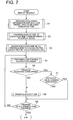
Fig. 7 . - When a display of the JOB scale screen is requested from a user, the procedures by
image control CPU 113 are started. In this case, when a scheduling button is selected by operations ofoperation system 140, theimage control CPU 113 draws a background section other than JOB bar JB that constitutes JOB schedule screen. The background section includes numerical values corresponding to a sheet size and a display scale which are displayed on connected tray,contracting button 320 and expandingbutton 322. - In step S1,
image control CPU 113 reads out and obtains execution order for each JOB, trays to be used, and JOB setting information for execution time. For example, in the case ofJOB 5,image control CPU 113 obtains information such as execution order of JOB "No. 5", tray to be used "Tray 2" and execution time "1 minute 40 seconds". After that, the flow moves to step s2. - In step S2,
image control CPU 113 converts execution time of each JOB obtained to the display size corresponding to display scale. In other words, theimage control CPU 113 calculates a length in the direction of time axis for JOB bar JB corresponding to each JOB, from the established display scale and from execution time of JOB. - In step S3, the
image control CPU 113 adds up execution times for all previous JOBs preceding its own JOB, and it calculates execution clock time of its own JOB (JOB starting clock time). For example, in the case ofJOB 5, an execution clock time for itsown JOB 5 is calculated by adding up execution times for JOB 1 -JOB 4. - In step S4, the
image control CPU 113 calculates image drawing positions in JOB schedule screen for each JOB, based on JOB setting information such as execution order of each JOB, a tray to be used, execution time and execution clock time all acquired fromHDD 127, and it prepares drawing images in the order of execution clock time. - In step S5, it is judged whether the image drawing position thus prepared is overlapped with that of previous JOB or not. When the prepared image drawing position is judged not to be overlapped with previous JOB (stepS5, NO), information of objective JOB is drawn on JOB schedule screen 300 (step S6). Image drawing of the aforesaid JOB is continued in the order of clock time until the moment when image drawings for all JOBs are completed (stepS8). On the other hand, when a position of image drawing for the JOB that becomes objective in the aforesaid step S5 is overlapped with that of the previous JOB (step S5, YES), the previous JOB is judged whether it is warning display or not (step S7). For example, information of JOB displayed to be in black as mentioned above corresponds to warning display. When the previous JOB is not warning display (step S7, NO), image drawing is conducted for the objective JOB (step S6). In this case, JOB information is displayed to be overlapped, but the warning display is not included in the overlapped portion. Image drawings for respective JOBs are continued in the order of clock time until the moment when image drawings for all JOBs are completed (step s8).
- On the other hand, when the previous JOB is warning display (step S7, YES), a flow moves to the image drawing processing of the succeeding JOB (from step S8 to step s4) without conducting image drawing for the objective JOB. Due to this, with respect to JOB information for warning display, information of following JOB is not displayed to be overlapped, and warning display is indicated on the uppermost layer constantly. When image drawings for all JOBs are completed, processing is terminated (step S8, YES).
- Incidentally, in the aforesaid example, there has been given an explanation about an occasion wherein a scale of each JOB bar JB is changed equally by a change of the display scale of the JOB schedule screen. In the following explanation,
Fig. 8 - Fig. 10 will be used to explain a method to display each JOB bar JB on JOB schedule screen without being based on the changed display scale, when the display scale is changed. - With respect to
JOB schedule screen 300d shown inFig. 8 , JOB bars JB 1 -JB 7 are displayed with display scale of 30 minutes in the same way as inFig. 3 . In this example, the JOB barsJB 2 andJB 7 are displayed to be in black, and other JOB bars are displayed through halftone, andJOB bars JB 2 andJB 7 are those to display warning. - A display scale of the aforesaid
JOB schedule screen 300d is changed, and those displayed by display scale of 4 hours through a traditional display method areJOB schedule screen 300e shown inFig. 9 . In this screen,JOB bar JB 8 which was not displayed through the scale of 30 minutes is displayed newly. However, in this example, when changing the display scale, each JOB bar is not changed to be in the same change of the scale, but each JOB bar is displayed in a size that is larger than an original scale change. Namely, in the present example, the JOB bar is displayed to be extended in terms of a length in the direction toward the front and the direction toward the rear, in the direction of time axis. Due to this, it becomes easy to recognize each JOB bar visually, also in the case of changing a display scale. Incidentally, though all JOB bars are displayed after being extended in the direction of time axis, in this example, it is also possible to display only JOB bars which are in the prescribed length or shorter, after changing a form. - However, even in the case of the display method of this kind, if JOBs are continued for the same tray, image drawing positions for JOBs are forced to be overlapped as is shown in
Fig. 9 , thus, a part or the whole of JOB information pieces are positioned to the lower layer side, resulting in a problem that visual confirmation is difficult. In theJOB schedule screen 300d inFig. 8 before the scale change,JOB bar JB 2 is displayed remarkably to be in black as a warning display. However, in theJOB schedule screen 300e inFig. 9 after the scale change, only a mere portion of theJOB bar JB 2 is displayed in the upper layer side, and the greater part of theJOB bar JB 2 is positioned in the lower layer side of other JOB bars JB3 and JB5, resulting in a problem that visual confirmation is difficult. - Even in the case of the display situation mentioned above, it is possible to display the JOB bar for warning display on the uppermost layer, in the display method of the invention.
JOB schedule screen 300f shown inFig. 10 is one in which JOB bar JB2 is displayed on the uppermost layer. The JOB bar JB2 is displayed to be larger than its original size of display scale, thus, it is more easy for a user to recognize visually, and operations for selection can be conducted easily. - Meanwhile, though the explanation has been given for the occasion wherein each JOB bar is displayed to be larger in terms of a size than an actual display scale in the aforesaid situation, it is also possible to use a method wherein each JOB bar is changed in terms of a shape to serve as a mark, so that visual confirmation may become easy, and in this case again, visual recognition and selection operations become easy, by displaying JOB bar for warning display in the uppermost layer. It is further possible to use a method that is a combination of the aforesaid two methods to make the visual confirmation to be easier.
- The invention has been explained above, based on the aforesaid embodiment, and the invention is not limited to contents of the embodiment, and the disclosed embodiment can be varied without departing from the scope of the invention.
- On the schedule screen indicating the execution reserve state of JOB on the display section, when the information that should be recognized by a user exists in pieces of information displayed to be overlapped, in the case of displaying a part or the whole of information concerning the aforesaid two or more of the aforesaid JOBs depending on display conditions of the schedule screen, to be overlapped on the aforesaid schedule screen, the invention makes it possible for a user to confirm visually the information by controlling display so that the information that should be recognized by the user may be displayed on the uppermost layer.
- Incidentally, the display section has only to be one that can display the aforesaid information, and CRT, a liquid crystal display and an organic EL can be used. Further, it is possible to constitute a display section with a touch panel that serves also as an inputting section. On the touch panel, it is possible to conduct detection for the display panel section and for a coordinate position corresponding to a button position for the display panel. Further, an inputting portion may also be one composed of a mouse and a cursor key, in addition to the foregoing. In a word, the inputting portion has only to be one that can select the information of JOB displayed on a schedule screen.
- As the aforesaid display conditions, there are given display scales on the schedule screen. For example, in some display scales, it is necessary to display a part or the whole of the information to be overlapped, when it is difficult to display information concerning the aforesaid two or more JOBs on a thorough noninterference basis. In this overlapped display, when the information that should be recognized by a user, such as the information of warning becomes to be invisible utterly, or when the aforesaid information is invisible except only an extremely a part of the information, visual confirmation by a user becomes difficult. Therefore, when this information is displayed on the uppermost layer, visibility by a user becomes possible. Display on the uppermost layer may either be one where all of display areas concerning the information are displayed or be one wherein recognition and selection operations for a user are made to be easy by enlarging its area to the minimum unit or more, though only a part of display area of information is displayed, and the entire portion of information area is not covered when the display area of the information is limited to a part to be less than a minimum unit.
- Incidentally, when a change of a display scale is possible, and when the display scale has been changed in the direction for the display scale to be reduced, it is also possible to conduct a display of information concerning the aforesaid JOB by changing a size and a shape of the display to those which make a user to recognize easily, without being based on the changed display scale. Owing to this display, it is possible to display the information that should be recognized by a user on the uppermost layer to make visual confirmation to be possible, when information that should be recognized by a user is in existence in information displayed to be overlapped in the same way as in the foregoing, even in the case where a part or the whole of the information are overlapped.
- Information relating to JOB can be displayed by character information or by functional buttons, and selecting operations for the information can be carried out by an input section such as a touch panel or a mouse. Further, for the information displayed on the uppermost layer, it is possible to make selecting operations for the aforesaid information to be possible equally. After the selecting operations have been conducted, processing established in advance is carried out. For example, it is possible to indicate a display related to the aforesaid JOB on the uppermost layer through a pop-up screen. When the information which should be recognized by a user is a warning, it is possible to conduct detailed display of the warning as a display related to the JOB.
- As explained above, the present invention makes it possible for a user to recognize surely the information that should be recognized by the user such as warning information by displaying the aforesaid information on the uppermost layer, even in the case where plural pieces of information are in existence in the same position within the schedule screen. Further, if information items displayed on the uppermost layer are made to be possible for selecting operations, there is an effect to make it possible to operate target buttons including warning information preferentially.
Claims (17)
- A display method for displaying a schedule screen (300) which indicates an execution reservation state of a plurality of JOBs on a display section (141), characterised by:displaying information concerning two or more of the JOBs as JOB images by superimposing the JOB images in a same area on the schedule screen, according to a display scale condition of the schedule screen; anddisplaying, in cases where information relating to a JOB required to be recognized by a user exists in the superimposed JOB images, a JOB image of a JOB to which the information required to be recognized by the user relates on top of a JOB image of another of said plurality of JOBs, so that the JOB image of the JOB to which the information is required to be recognized by the user is visible.
- The display method of claim 1, further comprising a step of displaying the information concerning the two or more of JOBs according to a change of the display scale, wherein a part or whole of the information concerning the JOBs is displayed with a scale different from the scale after the change or with a deformed shape.
- The display method of claim 1 or claim 2, wherein the information required to be recognized by the user is a warning to the user.
- The display method of any one of claims 1 - 3, wherein the JOB image of the JOB to which the information required to be recognized by the user relates, which is displayed on top of the JOB image of the other of said plurality of JOBs, is capable of selection operation by a user.
- The display method of claim 4, further comprising a step of displaying through the selection operation, on the display section, information relating to the JOB image of the JOB to which the information required to be recognized by the user relates.
- The display method of any one of claims 1 - 5, wherein the method is for displaying the schedule screen which displays the execution reservation state of JOBs to execute printing through image formation, on the display section of an image formation apparatus (1).
- The display method of any preceding claim, wherein each JOB image comprises a JOB bar (JB) having a size on the schedule screen corresponding to the time required for the JOB of that JOB bar to be executed.
- A display device comprising:a display section (141) operable to display information; anda control section (142) operable to control the display section,characterised by the control section being configured to control the display section to:display information concerning two or more of the JOBs as JOB images by superimposing the JOB images in a same area on the schedule screen, according to a display scale condition of the schedule screen; anddisplay, in cases where information relating to a JOB required to be recognized by a user exists in the superimposed JOB images, a JOB image of a JOB to which the information required to be recognized by the user relates on top of a JOB image of another of said plurality of JOBs, so that the JOB image of the JOB to which the information is required to be recognized by the user is visible.
- The display device of claim 8, wherein the control section is operable to enable the display scale to be changed, and in cases of displaying the information concerning the two or more of JOBs according to a change of the display scale, is operable to control the display section to display a part or whole of the information concerning the two or more of JOBs with a scale different from the scale after the change or with a deformed shape.
- The display device of claim 8 or claim 9, wherein the information required to be recognized by the user is a warning to the user.
- The display device of any one of claims 8 - 10, wherein the information displayed by superimposing on the schedule screen is character information.
- The display device of any one of claims 8 - 10, wherein the information displayed by superimposing on the schedule screen are function buttons capable of selection operation.
- The display device of claim 12, wherein in cases where the function button which is required to be recognized by a user exists in the function buttons displayed by superimposing, the control section is operable to control the display section to display the function button required to be recognized by the user on an uppermost layer, and to enable the selection operation of the function button.
- The display device of any one of claims 8 - 13, further comprising an input section which is controllable by the control section, and through which an operation input by a user is capable, wherein the control section is operable to enable the input section to accept a selection operation of the JOB image of the JOB to which the information required to be recognized by the user relates, which is displayed on top of the JOB image of the other of said plurality of JOBs.
- The display device of any one of claims 12 - 14, wherein the control section is operable to control, according to the selection operation, the display section to display information relating to the information displayed on the uppermost layer, on the upper most layer of the display section.
- The display device of any of claims 8 - 15, wherein each JOB image comprises a JOB bar (JB) having a size on the schedule screen corresponding to the time required for the JOB of that JOB bar to be executed.
- An image forming apparatus (1) comprising:an image forming section (150) operable to execute an image formation based on image data; anda display device according to any of claims 8 to 16, wherein the control section is operable to control the image forming section and the display section.
Applications Claiming Priority (1)
| Application Number | Priority Date | Filing Date | Title |
|---|---|---|---|
| JP2009232644A JP5692485B2 (en) | 2009-10-06 | 2009-10-06 | Display method, display method of image forming apparatus, display apparatus, image forming apparatus, and program |
Publications (3)
| Publication Number | Publication Date |
|---|---|
| EP2309714A2 EP2309714A2 (en) | 2011-04-13 |
| EP2309714A3 EP2309714A3 (en) | 2012-08-22 |
| EP2309714B1 true EP2309714B1 (en) | 2019-08-28 |
Family
ID=43128268
Family Applications (1)
| Application Number | Title | Priority Date | Filing Date |
|---|---|---|---|
| EP10181860.7A Active EP2309714B1 (en) | 2009-10-06 | 2010-09-29 | Display method, display method of image forming apparatus, display device and image forming apparatus |
Country Status (4)
| Country | Link |
|---|---|
| US (1) | US9344591B2 (en) |
| EP (1) | EP2309714B1 (en) |
| JP (1) | JP5692485B2 (en) |
| CN (1) | CN102035980B (en) |
Families Citing this family (10)
| Publication number | Priority date | Publication date | Assignee | Title |
|---|---|---|---|---|
| EP2157775A1 (en) * | 2008-08-20 | 2010-02-24 | Konica Minolta Business Technologies, INC. | Image forming apparatus with two-dimensional display of job scheduling screen |
| JP5527165B2 (en) * | 2010-11-04 | 2014-06-18 | ブラザー工業株式会社 | COMMUNICATION DEVICE AND COMMUNICATION DEVICE PROGRAM |
| CN102279718A (en) * | 2011-08-03 | 2011-12-14 | 北京数码大方科技有限公司 | Method and device for printing drawings |
| JP2013216071A (en) * | 2012-04-12 | 2013-10-24 | Canon Inc | Printing system, printing apparatus, printing apparatus control method, and program |
| JP2015003498A (en) * | 2013-06-24 | 2015-01-08 | キヤノン株式会社 | Job processing device, display control method for job processing device, and program |
| WO2015173060A1 (en) * | 2014-05-16 | 2015-11-19 | Oce-Technologies B.V. | A method for a print fleet system |
| EP3104228B1 (en) * | 2015-06-10 | 2019-08-07 | Oce-Technologies B.V. | Method for scheduling a reload of supply material in a printing system |
| JP7056025B2 (en) * | 2017-07-26 | 2022-04-19 | 富士フイルムビジネスイノベーション株式会社 | Display device, printing device, print control device and display program |
| JP6972734B2 (en) * | 2017-07-26 | 2021-11-24 | 富士フイルムビジネスイノベーション株式会社 | Display device, printing device, print control device and display program |
| JP7057101B2 (en) * | 2017-11-17 | 2022-04-19 | キヤノン株式会社 | Image forming device and its control method |
Family Cites Families (33)
| Publication number | Priority date | Publication date | Assignee | Title |
|---|---|---|---|---|
| US5260805A (en) * | 1991-08-22 | 1993-11-09 | Xerox Corporation | Process for identifying programming conflicts in electronic printing systems |
| JPH0827701B2 (en) | 1993-02-12 | 1996-03-21 | 株式会社富士通ソーシアルサイエンスラボラトリ | Overlay display method |
| US20020054103A1 (en) * | 1997-10-28 | 2002-05-09 | Shinya Mizuno | Method of display scrolling along a timebase and an apparatus for performing the method |
| US7249356B1 (en) * | 1999-04-29 | 2007-07-24 | Fisher-Rosemount Systems, Inc. | Methods and structure for batch processing event history processing and viewing |
| JP2000351259A (en) * | 1999-06-14 | 2000-12-19 | Minolta Co Ltd | Imaging apparatus |
| JP2001022850A (en) * | 1999-07-08 | 2001-01-26 | Sharp Corp | Method and device for managing schedule, and recording medium storing schedule management program |
| US6597378B1 (en) * | 2000-01-18 | 2003-07-22 | Seiko Epson Corporation | Display device, portable information processing apparatus, information storage medium, and electronic apparatus |
| JP2001333233A (en) * | 2000-05-22 | 2001-11-30 | Sharp Corp | Processor |
| JP4028955B2 (en) * | 2000-08-18 | 2008-01-09 | 株式会社リコー | PRINT CONTROL DEVICE, PRINT CONTROL METHOD, AND COMPUTER-READABLE RECORDING MEDIUM RECORDING PROGRAM FOR CAUSING COMPUTER TO EXECUTE THE METHOD |
| JP3971553B2 (en) * | 2000-08-18 | 2007-09-05 | 株式会社リコー | PRINT CONTROL DEVICE, PRINT CONTROL METHOD, AND COMPUTER-READABLE RECORDING MEDIUM CONTAINING PROGRAM FOR CAUSING COMPUTER TO EXECUTE THE METHOD |
| JP4092068B2 (en) * | 2000-11-10 | 2008-05-28 | 株式会社リコー | Printing control apparatus, printing apparatus, printing system, and recording medium for printing control |
| JP2002342046A (en) * | 2001-03-20 | 2002-11-29 | Oce Technologies Bv | Method for managing printing queue and printer |
| JP2003191579A (en) * | 2001-12-27 | 2003-07-09 | Sharp Corp | Electronic controller |
| NL1023326C2 (en) * | 2003-05-02 | 2004-11-03 | Oce Tech Bv | Printing system and method for using this system. |
| EP1652081A2 (en) * | 2003-07-10 | 2006-05-03 | Computer Associates Think, Inc. | Dynamic web server |
| JP4592081B2 (en) * | 2004-04-28 | 2010-12-01 | キヤノン株式会社 | Print schedule control apparatus, print schedule control method, and program |
| JP4298584B2 (en) * | 2004-05-19 | 2009-07-22 | キヤノン株式会社 | Information processing apparatus and information processing method |
| JP2006065803A (en) * | 2004-08-30 | 2006-03-09 | Canon Inc | Information processor, control method therefor, and program |
| JP4991110B2 (en) * | 2005-01-24 | 2012-08-01 | 日本電気株式会社 | Schedule display system and method, and program for schedule display |
| JP4614387B2 (en) * | 2005-03-02 | 2011-01-19 | キヤノン株式会社 | Information processing apparatus, process management method, and program thereof |
| US7458033B2 (en) * | 2005-03-17 | 2008-11-25 | Oracle International Corporation | Direct manipulation of time scale |
| JP4724474B2 (en) * | 2005-06-10 | 2011-07-13 | キヤノン株式会社 | Image forming job management apparatus and method, and program |
| KR100906918B1 (en) * | 2005-06-30 | 2009-07-08 | 올림푸스 가부시키가이샤 | Retrieval system and retrieval method |
| US7853465B2 (en) * | 2005-12-02 | 2010-12-14 | Oracle International Corp. | Methods and apparatus to present event information with respect to a timeline |
| US7777908B2 (en) * | 2006-02-24 | 2010-08-17 | Fujifilm North America Corporation | Method of scheduling photograph print jobs |
| US20080154688A1 (en) * | 2006-12-22 | 2008-06-26 | Sap Ag | Groupware assistance tool providing regular appointments overview |
| JP5147383B2 (en) * | 2007-12-20 | 2013-02-20 | キヤノン株式会社 | Image processing apparatus, image processing apparatus control method, and program |
| US20100017740A1 (en) * | 2008-07-17 | 2010-01-21 | Microsoft Corporation | Pan and zoom control |
| EP2154577B1 (en) * | 2008-08-11 | 2017-03-01 | Konica Minolta Business Technologies, Inc. | Image forming apparatus |
| EP2157775A1 (en) * | 2008-08-20 | 2010-02-24 | Konica Minolta Business Technologies, INC. | Image forming apparatus with two-dimensional display of job scheduling screen |
| US8683390B2 (en) * | 2008-10-01 | 2014-03-25 | Microsoft Corporation | Manipulation of objects on multi-touch user interface |
| JP5359693B2 (en) * | 2009-08-28 | 2013-12-04 | コニカミノルタ株式会社 | Image forming apparatus and image forming method |
| JP5413065B2 (en) * | 2009-09-03 | 2014-02-12 | コニカミノルタ株式会社 | Image forming apparatus and image forming method |
-
2009
- 2009-10-06 JP JP2009232644A patent/JP5692485B2/en active Active
-
2010
- 2010-09-29 EP EP10181860.7A patent/EP2309714B1/en active Active
- 2010-09-29 CN CN2010105023675A patent/CN102035980B/en active Active
- 2010-10-01 US US12/895,989 patent/US9344591B2/en active Active
Non-Patent Citations (1)
| Title |
|---|
| None * |
Also Published As
| Publication number | Publication date |
|---|---|
| US20110083095A1 (en) | 2011-04-07 |
| CN102035980A (en) | 2011-04-27 |
| CN102035980B (en) | 2013-12-11 |
| US9344591B2 (en) | 2016-05-17 |
| EP2309714A2 (en) | 2011-04-13 |
| JP5692485B2 (en) | 2015-04-01 |
| JP2011081144A (en) | 2011-04-21 |
| EP2309714A3 (en) | 2012-08-22 |
Similar Documents
| Publication | Publication Date | Title |
|---|---|---|
| EP2309714B1 (en) | Display method, display method of image forming apparatus, display device and image forming apparatus | |
| US10311344B2 (en) | Processing apparatus, display device and non-transitory computer readable medium storing program | |
| EP2293536B1 (en) | Image forming apparatus and image forming method | |
| US9363394B2 (en) | Information processing apparatus capable of setting insert, image forming apparatus, method of controlling the information processing apparatus, and storage medium | |
| US8233815B2 (en) | Image forming apparatus reserving a plurality of jobs | |
| US9578193B2 (en) | Quick operation user interface for a multifunction printing device | |
| US8437651B2 (en) | Image forming apparatus and method for displaying reserved jobs on a list | |
| US8285168B2 (en) | Image forming apparatus | |
| US8982370B2 (en) | Image forming apparatus and image forming method | |
| EP3521936B1 (en) | Display input device, image forming apparatus, control method for display input device | |
| EP2133752A2 (en) | Tab sheet setting apparatus and tab sheet setting program | |
| JP2013107247A (en) | Information processing apparatus and program | |
| US20130050732A1 (en) | Image forming apparatus which is capable of displaying real size preview, method of controlling the same, and storage medium | |
| JP7010302B2 (en) | Information processing device, job setting method | |
| JP2021165928A (en) | Image processing device and image processing method | |
| JP2005107026A (en) | Image forming apparatus | |
| JP2012006220A (en) | Image forming apparatus |
Legal Events
| Date | Code | Title | Description |
|---|---|---|---|
| PUAI | Public reference made under article 153(3) epc to a published international application that has entered the european phase |
Free format text: ORIGINAL CODE: 0009012 |
|
| AK | Designated contracting states |
Kind code of ref document: A2 Designated state(s): AL AT BE BG CH CY CZ DE DK EE ES FI FR GB GR HR HU IE IS IT LI LT LU LV MC MK MT NL NO PL PT RO SE SI SK SM TR |
|
| AX | Request for extension of the european patent |
Extension state: BA ME RS |
|
| PUAL | Search report despatched |
Free format text: ORIGINAL CODE: 0009013 |
|
| AK | Designated contracting states |
Kind code of ref document: A3 Designated state(s): AL AT BE BG CH CY CZ DE DK EE ES FI FR GB GR HR HU IE IS IT LI LT LU LV MC MK MT NL NO PL PT RO SE SI SK SM TR |
|
| AX | Request for extension of the european patent |
Extension state: BA ME RS |
|
| RIC1 | Information provided on ipc code assigned before grant |
Ipc: H04N 1/00 20060101AFI20120717BHEP |
|
| 17P | Request for examination filed |
Effective date: 20130222 |
|
| STAA | Information on the status of an ep patent application or granted ep patent |
Free format text: STATUS: EXAMINATION IS IN PROGRESS |
|
| 17Q | First examination report despatched |
Effective date: 20161129 |
|
| GRAP | Despatch of communication of intention to grant a patent |
Free format text: ORIGINAL CODE: EPIDOSNIGR1 |
|
| STAA | Information on the status of an ep patent application or granted ep patent |
Free format text: STATUS: GRANT OF PATENT IS INTENDED |
|
| INTG | Intention to grant announced |
Effective date: 20190426 |
|
| GRAS | Grant fee paid |
Free format text: ORIGINAL CODE: EPIDOSNIGR3 |
|
| GRAA | (expected) grant |
Free format text: ORIGINAL CODE: 0009210 |
|
| STAA | Information on the status of an ep patent application or granted ep patent |
Free format text: STATUS: THE PATENT HAS BEEN GRANTED |
|
| AK | Designated contracting states |
Kind code of ref document: B1 Designated state(s): AL AT BE BG CH CY CZ DE DK EE ES FI FR GB GR HR HU IE IS IT LI LT LU LV MC MK MT NL NO PL PT RO SE SI SK SM TR |
|
| REG | Reference to a national code |
Ref country code: GB Ref legal event code: FG4D |
|
| REG | Reference to a national code |
Ref country code: CH Ref legal event code: EP |
|
| REG | Reference to a national code |
Ref country code: AT Ref legal event code: REF Ref document number: 1173872 Country of ref document: AT Kind code of ref document: T Effective date: 20190915 |
|
| REG | Reference to a national code |
Ref country code: IE Ref legal event code: FG4D |
|
| REG | Reference to a national code |
Ref country code: DE Ref legal event code: R096 Ref document number: 602010060748 Country of ref document: DE |
|
| REG | Reference to a national code |
Ref country code: NL Ref legal event code: MP Effective date: 20190828 |
|
| REG | Reference to a national code |
Ref country code: LT Ref legal event code: MG4D |
|
| PG25 | Lapsed in a contracting state [announced via postgrant information from national office to epo] |
Ref country code: LT Free format text: LAPSE BECAUSE OF FAILURE TO SUBMIT A TRANSLATION OF THE DESCRIPTION OR TO PAY THE FEE WITHIN THE PRESCRIBED TIME-LIMIT Effective date: 20190828 Ref country code: PT Free format text: LAPSE BECAUSE OF FAILURE TO SUBMIT A TRANSLATION OF THE DESCRIPTION OR TO PAY THE FEE WITHIN THE PRESCRIBED TIME-LIMIT Effective date: 20191230 Ref country code: HR Free format text: LAPSE BECAUSE OF FAILURE TO SUBMIT A TRANSLATION OF THE DESCRIPTION OR TO PAY THE FEE WITHIN THE PRESCRIBED TIME-LIMIT Effective date: 20190828 Ref country code: BG Free format text: LAPSE BECAUSE OF FAILURE TO SUBMIT A TRANSLATION OF THE DESCRIPTION OR TO PAY THE FEE WITHIN THE PRESCRIBED TIME-LIMIT Effective date: 20191128 Ref country code: NL Free format text: LAPSE BECAUSE OF FAILURE TO SUBMIT A TRANSLATION OF THE DESCRIPTION OR TO PAY THE FEE WITHIN THE PRESCRIBED TIME-LIMIT Effective date: 20190828 Ref country code: NO Free format text: LAPSE BECAUSE OF FAILURE TO SUBMIT A TRANSLATION OF THE DESCRIPTION OR TO PAY THE FEE WITHIN THE PRESCRIBED TIME-LIMIT Effective date: 20191128 Ref country code: SE Free format text: LAPSE BECAUSE OF FAILURE TO SUBMIT A TRANSLATION OF THE DESCRIPTION OR TO PAY THE FEE WITHIN THE PRESCRIBED TIME-LIMIT Effective date: 20190828 Ref country code: FI Free format text: LAPSE BECAUSE OF FAILURE TO SUBMIT A TRANSLATION OF THE DESCRIPTION OR TO PAY THE FEE WITHIN THE PRESCRIBED TIME-LIMIT Effective date: 20190828 |
|
| PG25 | Lapsed in a contracting state [announced via postgrant information from national office to epo] |
Ref country code: IS Free format text: LAPSE BECAUSE OF FAILURE TO SUBMIT A TRANSLATION OF THE DESCRIPTION OR TO PAY THE FEE WITHIN THE PRESCRIBED TIME-LIMIT Effective date: 20191228 Ref country code: GR Free format text: LAPSE BECAUSE OF FAILURE TO SUBMIT A TRANSLATION OF THE DESCRIPTION OR TO PAY THE FEE WITHIN THE PRESCRIBED TIME-LIMIT Effective date: 20191129 Ref country code: ES Free format text: LAPSE BECAUSE OF FAILURE TO SUBMIT A TRANSLATION OF THE DESCRIPTION OR TO PAY THE FEE WITHIN THE PRESCRIBED TIME-LIMIT Effective date: 20190828 Ref country code: AL Free format text: LAPSE BECAUSE OF FAILURE TO SUBMIT A TRANSLATION OF THE DESCRIPTION OR TO PAY THE FEE WITHIN THE PRESCRIBED TIME-LIMIT Effective date: 20190828 Ref country code: LV Free format text: LAPSE BECAUSE OF FAILURE TO SUBMIT A TRANSLATION OF THE DESCRIPTION OR TO PAY THE FEE WITHIN THE PRESCRIBED TIME-LIMIT Effective date: 20190828 |
|
| REG | Reference to a national code |
Ref country code: AT Ref legal event code: MK05 Ref document number: 1173872 Country of ref document: AT Kind code of ref document: T Effective date: 20190828 |
|
| PG25 | Lapsed in a contracting state [announced via postgrant information from national office to epo] |
Ref country code: TR Free format text: LAPSE BECAUSE OF FAILURE TO SUBMIT A TRANSLATION OF THE DESCRIPTION OR TO PAY THE FEE WITHIN THE PRESCRIBED TIME-LIMIT Effective date: 20190828 |
|
| PG25 | Lapsed in a contracting state [announced via postgrant information from national office to epo] |
Ref country code: AT Free format text: LAPSE BECAUSE OF FAILURE TO SUBMIT A TRANSLATION OF THE DESCRIPTION OR TO PAY THE FEE WITHIN THE PRESCRIBED TIME-LIMIT Effective date: 20190828 Ref country code: DK Free format text: LAPSE BECAUSE OF FAILURE TO SUBMIT A TRANSLATION OF THE DESCRIPTION OR TO PAY THE FEE WITHIN THE PRESCRIBED TIME-LIMIT Effective date: 20190828 Ref country code: EE Free format text: LAPSE BECAUSE OF FAILURE TO SUBMIT A TRANSLATION OF THE DESCRIPTION OR TO PAY THE FEE WITHIN THE PRESCRIBED TIME-LIMIT Effective date: 20190828 Ref country code: IT Free format text: LAPSE BECAUSE OF FAILURE TO SUBMIT A TRANSLATION OF THE DESCRIPTION OR TO PAY THE FEE WITHIN THE PRESCRIBED TIME-LIMIT Effective date: 20190828 Ref country code: RO Free format text: LAPSE BECAUSE OF FAILURE TO SUBMIT A TRANSLATION OF THE DESCRIPTION OR TO PAY THE FEE WITHIN THE PRESCRIBED TIME-LIMIT Effective date: 20190828 Ref country code: PL Free format text: LAPSE BECAUSE OF FAILURE TO SUBMIT A TRANSLATION OF THE DESCRIPTION OR TO PAY THE FEE WITHIN THE PRESCRIBED TIME-LIMIT Effective date: 20190828 |
|
| PG25 | Lapsed in a contracting state [announced via postgrant information from national office to epo] |
Ref country code: SM Free format text: LAPSE BECAUSE OF FAILURE TO SUBMIT A TRANSLATION OF THE DESCRIPTION OR TO PAY THE FEE WITHIN THE PRESCRIBED TIME-LIMIT Effective date: 20190828 Ref country code: SK Free format text: LAPSE BECAUSE OF FAILURE TO SUBMIT A TRANSLATION OF THE DESCRIPTION OR TO PAY THE FEE WITHIN THE PRESCRIBED TIME-LIMIT Effective date: 20190828 Ref country code: IS Free format text: LAPSE BECAUSE OF FAILURE TO SUBMIT A TRANSLATION OF THE DESCRIPTION OR TO PAY THE FEE WITHIN THE PRESCRIBED TIME-LIMIT Effective date: 20200224 Ref country code: MC Free format text: LAPSE BECAUSE OF FAILURE TO SUBMIT A TRANSLATION OF THE DESCRIPTION OR TO PAY THE FEE WITHIN THE PRESCRIBED TIME-LIMIT Effective date: 20190828 Ref country code: CZ Free format text: LAPSE BECAUSE OF FAILURE TO SUBMIT A TRANSLATION OF THE DESCRIPTION OR TO PAY THE FEE WITHIN THE PRESCRIBED TIME-LIMIT Effective date: 20190828 |
|
| REG | Reference to a national code |
Ref country code: CH Ref legal event code: PL |
|
| REG | Reference to a national code |
Ref country code: DE Ref legal event code: R097 Ref document number: 602010060748 Country of ref document: DE |
|
| PLBE | No opposition filed within time limit |
Free format text: ORIGINAL CODE: 0009261 |
|
| STAA | Information on the status of an ep patent application or granted ep patent |
Free format text: STATUS: NO OPPOSITION FILED WITHIN TIME LIMIT |
|
| PG2D | Information on lapse in contracting state deleted |
Ref country code: IS |
|
| PG25 | Lapsed in a contracting state [announced via postgrant information from national office to epo] |
Ref country code: CH Free format text: LAPSE BECAUSE OF NON-PAYMENT OF DUE FEES Effective date: 20190930 Ref country code: LI Free format text: LAPSE BECAUSE OF NON-PAYMENT OF DUE FEES Effective date: 20190930 Ref country code: IE Free format text: LAPSE BECAUSE OF NON-PAYMENT OF DUE FEES Effective date: 20190929 Ref country code: LU Free format text: LAPSE BECAUSE OF NON-PAYMENT OF DUE FEES Effective date: 20190929 |
|
| 26N | No opposition filed |
Effective date: 20200603 |
|
| REG | Reference to a national code |
Ref country code: BE Ref legal event code: MM Effective date: 20190930 |
|
| PG25 | Lapsed in a contracting state [announced via postgrant information from national office to epo] |
Ref country code: BE Free format text: LAPSE BECAUSE OF NON-PAYMENT OF DUE FEES Effective date: 20190930 Ref country code: SI Free format text: LAPSE BECAUSE OF FAILURE TO SUBMIT A TRANSLATION OF THE DESCRIPTION OR TO PAY THE FEE WITHIN THE PRESCRIBED TIME-LIMIT Effective date: 20190828 |
|
| PG25 | Lapsed in a contracting state [announced via postgrant information from national office to epo] |
Ref country code: CY Free format text: LAPSE BECAUSE OF FAILURE TO SUBMIT A TRANSLATION OF THE DESCRIPTION OR TO PAY THE FEE WITHIN THE PRESCRIBED TIME-LIMIT Effective date: 20190828 |
|
| PG25 | Lapsed in a contracting state [announced via postgrant information from national office to epo] |
Ref country code: MT Free format text: LAPSE BECAUSE OF FAILURE TO SUBMIT A TRANSLATION OF THE DESCRIPTION OR TO PAY THE FEE WITHIN THE PRESCRIBED TIME-LIMIT Effective date: 20190828 Ref country code: HU Free format text: LAPSE BECAUSE OF FAILURE TO SUBMIT A TRANSLATION OF THE DESCRIPTION OR TO PAY THE FEE WITHIN THE PRESCRIBED TIME-LIMIT; INVALID AB INITIO Effective date: 20100929 |
|
| PG25 | Lapsed in a contracting state [announced via postgrant information from national office to epo] |
Ref country code: MK Free format text: LAPSE BECAUSE OF FAILURE TO SUBMIT A TRANSLATION OF THE DESCRIPTION OR TO PAY THE FEE WITHIN THE PRESCRIBED TIME-LIMIT Effective date: 20190828 |
|
| P01 | Opt-out of the competence of the unified patent court (upc) registered |
Effective date: 20230510 |
|
| PGFP | Annual fee paid to national office [announced via postgrant information from national office to epo] |
Ref country code: GB Payment date: 20230810 Year of fee payment: 14 |
|
| PGFP | Annual fee paid to national office [announced via postgrant information from national office to epo] |
Ref country code: FR Payment date: 20230808 Year of fee payment: 14 Ref country code: DE Payment date: 20230802 Year of fee payment: 14 |