JP7057101B2 - Image forming device and its control method - Google Patents

Image forming device and its control method Download PDF

Info

Publication number
JP7057101B2
JP7057101B2 JP2017221882A JP2017221882A JP7057101B2 JP 7057101 B2 JP7057101 B2 JP 7057101B2 JP 2017221882 A JP2017221882 A JP 2017221882A JP 2017221882 A JP2017221882 A JP 2017221882A JP 7057101 B2 JP7057101 B2 JP 7057101B2
Authority
JP
Japan
Prior art keywords
paper feed
print job
feed device
print
user
Prior art date
Legal status (The legal status is an assumption and is not a legal conclusion. Google has not performed a legal analysis and makes no representation as to the accuracy of the status listed.)
Active
Application number
JP2017221882A
Other languages
Japanese (ja)
Other versions
JP2019093556A (en
JP2019093556A5 (en
Inventor
孝介 辻田
Current Assignee (The listed assignees may be inaccurate. Google has not performed a legal analysis and makes no representation or warranty as to the accuracy of the list.)
Canon Inc
Original Assignee
Canon Inc
Priority date (The priority date is an assumption and is not a legal conclusion. Google has not performed a legal analysis and makes no representation as to the accuracy of the date listed.)
Filing date
Publication date
Application filed by Canon Inc filed Critical Canon Inc
Priority to JP2017221882A priority Critical patent/JP7057101B2/en
Priority to US16/181,757 priority patent/US10990336B2/en
Publication of JP2019093556A publication Critical patent/JP2019093556A/en
Publication of JP2019093556A5 publication Critical patent/JP2019093556A5/ja
Application granted granted Critical
Publication of JP7057101B2 publication Critical patent/JP7057101B2/en
Active legal-status Critical Current
Anticipated expiration legal-status Critical

Links

Images

Classifications

    • GPHYSICS
    • G06COMPUTING; CALCULATING OR COUNTING
    • G06FELECTRIC DIGITAL DATA PROCESSING
    • G06F3/00Input arrangements for transferring data to be processed into a form capable of being handled by the computer; Output arrangements for transferring data from processing unit to output unit, e.g. interface arrangements
    • G06F3/12Digital output to print unit, e.g. line printer, chain printer
    • G06F3/1201Dedicated interfaces to print systems
    • G06F3/1223Dedicated interfaces to print systems specifically adapted to use a particular technique
    • G06F3/1237Print job management
    • G06F3/1239Restricting the usage of resources, e.g. usage or user levels, credit limit, consumables, special fonts
    • GPHYSICS
    • G06COMPUTING; CALCULATING OR COUNTING
    • G06FELECTRIC DIGITAL DATA PROCESSING
    • G06F3/00Input arrangements for transferring data to be processed into a form capable of being handled by the computer; Output arrangements for transferring data from processing unit to output unit, e.g. interface arrangements
    • G06F3/12Digital output to print unit, e.g. line printer, chain printer
    • G06F3/1201Dedicated interfaces to print systems
    • G06F3/1202Dedicated interfaces to print systems specifically adapted to achieve a particular effect
    • G06F3/121Facilitating exception or error detection and recovery, e.g. fault, media or consumables depleted
    • GPHYSICS
    • G06COMPUTING; CALCULATING OR COUNTING
    • G06FELECTRIC DIGITAL DATA PROCESSING
    • G06F3/00Input arrangements for transferring data to be processed into a form capable of being handled by the computer; Output arrangements for transferring data from processing unit to output unit, e.g. interface arrangements
    • G06F3/12Digital output to print unit, e.g. line printer, chain printer
    • G06F3/1201Dedicated interfaces to print systems
    • G06F3/1202Dedicated interfaces to print systems specifically adapted to achieve a particular effect
    • G06F3/1222Increasing security of the print job
    • GPHYSICS
    • G06COMPUTING; CALCULATING OR COUNTING
    • G06FELECTRIC DIGITAL DATA PROCESSING
    • G06F3/00Input arrangements for transferring data to be processed into a form capable of being handled by the computer; Output arrangements for transferring data from processing unit to output unit, e.g. interface arrangements
    • G06F3/12Digital output to print unit, e.g. line printer, chain printer
    • G06F3/1201Dedicated interfaces to print systems
    • G06F3/1223Dedicated interfaces to print systems specifically adapted to use a particular technique
    • G06F3/1237Print job management
    • G06F3/1253Configuration of print job parameters, e.g. using UI at the client
    • GPHYSICS
    • G06COMPUTING; CALCULATING OR COUNTING
    • G06FELECTRIC DIGITAL DATA PROCESSING
    • G06F3/00Input arrangements for transferring data to be processed into a form capable of being handled by the computer; Output arrangements for transferring data from processing unit to output unit, e.g. interface arrangements
    • G06F3/12Digital output to print unit, e.g. line printer, chain printer
    • G06F3/1201Dedicated interfaces to print systems
    • G06F3/1223Dedicated interfaces to print systems specifically adapted to use a particular technique
    • G06F3/1237Print job management
    • G06F3/126Job scheduling, e.g. queuing, determine appropriate device
    • G06F3/1264Job scheduling, e.g. queuing, determine appropriate device by assigning post-processing resources
    • GPHYSICS
    • G06COMPUTING; CALCULATING OR COUNTING
    • G06FELECTRIC DIGITAL DATA PROCESSING
    • G06F3/00Input arrangements for transferring data to be processed into a form capable of being handled by the computer; Output arrangements for transferring data from processing unit to output unit, e.g. interface arrangements
    • G06F3/12Digital output to print unit, e.g. line printer, chain printer
    • G06F3/1201Dedicated interfaces to print systems
    • G06F3/1278Dedicated interfaces to print systems specifically adapted to adopt a particular infrastructure
    • G06F3/1285Remote printer device, e.g. being remote from client or server

Description

本発明は、画像形成装置及びその制御方法に関する。 The present invention relates to an image forming apparatus and a control method thereof.

手差しトレイや給紙カセット等の複数の給紙装置を備える画像形成装置としてのMFPが知られている。MFPの各給紙装置には異なるサイズの用紙が収納され、MFPは、印刷ジョブが投入されると、複数の給紙装置の中から印刷ジョブに設定されたサイズの用紙を収納する給紙装置を特定し、特定した給紙装置の用紙を用いて印刷を行う。また、MFPでは、投入された印刷ジョブで使用する給紙装置をユーザが指定することも可能である(例えば、特許文献1参照)。例えば、ユーザは所定の給紙装置に普通用紙と厚さが異なる他の用紙をセットし、上記所定の給紙装置を指定する。これにより、ユーザは所望の種類の用紙の印刷結果物を得ることが可能となる。 An MFP is known as an image forming apparatus including a plurality of paper feed devices such as a manual feed tray and a paper feed cassette. Each paper feeder of the MFP stores different sizes of paper, and when a print job is submitted, the MFP is a paper feed device that stores the paper of the size set for the print job from among multiple paper feed devices. Is specified, and printing is performed using the paper of the specified paper feed device. Further, in the MFP, the user can also specify the paper feed device to be used in the submitted print job (see, for example, Patent Document 1). For example, the user sets another paper having a thickness different from that of ordinary paper in a predetermined paper feed device, and designates the predetermined paper feed device. This allows the user to obtain a print result of the desired type of paper.

特開2005-104614号公報Japanese Unexamined Patent Publication No. 2005-104614

しかしながら、オフィス等のように複数のユーザがMFPを利用する環境では、一のユーザが所望の種類の用紙を所定の給紙装置にセットし、一のユーザが投入した印刷ジョブの実行を待機している間に他のユーザによって投入された他の印刷ジョブが上記所定の給紙装置の用紙を使用してしまうという問題が生じる。 However, in an environment where multiple users use the MFP, such as in an office, one user sets a desired type of paper in a predetermined paper feed device and waits for the execution of the print job submitted by one user. During this period, another print job submitted by another user may use the paper of the predetermined paper feed device.

本発明の目的は、給紙装置の用紙がユーザに上記給紙装置の使用を設定された印刷ジョブ以外の他の印刷ジョブに使用されるのを防止することができる画像形成装置及びその制御方法を提供することにある。 An object of the present invention is an image forming apparatus and a method for controlling the same, which can prevent the paper of the paper feeding device from being used for other printing jobs other than the printing job in which the user is set to use the paper feeding device. To provide the law .

上記目的を達成するために、本発明の画像形成装置は、複数の給紙装置を備える画像形成装置であって、投入された印刷ジョブを実行する印刷ジョブ実行手段と、前記複数の給紙装置の中から前記印刷ジョブで使用する給紙装置をユーザに選択させる選択手段と、前記選択された給紙装置を前記印刷ジョブ以外の他の印刷ジョブで使用できないように制御する制御手段と、前記選択された給紙装置において前記制御手段による制御が解除されるまでの予測時間を通知する予測時間通知手段とを備えることを特徴とする。 In order to achieve the above object, the image forming apparatus of the present invention is an image forming apparatus including a plurality of feeding devices, and is a print job executing means for executing a submitted print job, and the plurality of feeding devices. A selection means for allowing the user to select a paper feed device to be used in the print job, a control means for controlling the selected paper feed device so that it cannot be used in a print job other than the print job, and the above. It is characterized by comprising a predicted time notification means for notifying the predicted time until the control by the control means is released in the selected paper feed device .

本発明によれば、給紙装置の用紙がユーザに上記給紙装置の使用を設定された印刷ジョブ以外の他の印刷ジョブに使用されるのを防止することができる。 According to the present invention, it is possible to prevent the paper of the paper feed device from being used for a print job other than the print job in which the user is set to use the paper feed device.

本発明の第1の実施の形態に係るMFPを含む通信システムの構成を概略的に示すネットワーク図である。FIG. 3 is a network diagram schematically showing a configuration of a communication system including an MFP according to the first embodiment of the present invention. 図1のMFPの機能構成を概略的に示すブロック図である。It is a block diagram which shows the functional structure of the MFP of FIG. 1 schematically. 図2の操作部の外観図である。It is an external view of the operation part of FIG. 図1のMFPのハードウェアの構成を説明するための図である。It is a figure for demonstrating the hardware configuration of the MFP of FIG. 図1のMFPのソフトウェアモジュールの構成を概略的に示すブロック図である。It is a block diagram which shows schematic structure of the software module of the MFP of FIG. 図1のPCにおいて印刷ジョブをホールドキューへ投入する指示が行われてからMFPにおいて上記印刷ジョブで使用する給紙装置の予約処理が行われるまでの処理の手順を示すシーケンス図である。It is a sequence diagram which shows the process procedure from the instruction to put a print job into a hold queue in the PC of FIG. 1 to the reservation process of the paper feed device used in the said print job in the MFP. 図1のMFPによって実行される第1の印刷予約受付処理の手順を示すフローチャートである。It is a flowchart which shows the procedure of the 1st print reservation acceptance processing executed by the MFP of FIG. 図2の操作部に表示される選択画面の一例を示す図である。It is a figure which shows an example of the selection screen displayed in the operation part of FIG. 図1のMFPによって管理される管理テーブルの一例を示す図である。It is a figure which shows an example of the management table managed by the MFP of FIG. 図2の操作部に表示される予約画面の一例を示す図である。It is a figure which shows an example of the reservation screen displayed on the operation part of FIG. 図2の操作部に表示される通知画面の一例を示す図である。It is a figure which shows an example of the notification screen displayed in the operation part of FIG. 図1のMFPにおいて予約された給紙装置の開操作を受け付けた際の処理の手順を示すシーケンス図である。It is a sequence diagram which shows the procedure of processing when the opening operation of the reserved paper feed apparatus is received in the MFP of FIG. 図1のMFPによって管理される管理テーブルの一例を示す図である。It is a figure which shows an example of the management table managed by the MFP of FIG. 図1のMFPによって実行されるロック制御処理の手順を示すフローチャートである。It is a flowchart which shows the procedure of the lock control processing executed by the MFP of FIG. 図2の操作部に表示される予約通知画面の一例を示す図である。It is a figure which shows an example of the reservation notification screen displayed in the operation part of FIG. 図1のMFPにおいて給紙装置が予約された印刷ジョブ及び給紙装置の予約が解除された印刷ジョブを実行する際の処理の手順を示すシーケンス図である。It is a sequence diagram which shows the procedure of processing at the time of executing the print job which reserved the paper feed device and the print job which canceled the reservation of a paper feed device in the MFP of FIG. 図1のMFPによって管理される管理テーブルの一例を示す図である。It is a figure which shows an example of the management table managed by the MFP of FIG. 図1のMFPにおいて給紙装置が予約された印刷ジョブ及び給紙装置の予約が解除された印刷ジョブを実行する際の処理の手順を示すシーケンス図である。It is a sequence diagram which shows the procedure of processing at the time of executing the print job which reserved the paper feed device and the print job which canceled the reservation of a paper feed device in the MFP of FIG. 図1のMFPによって実行される印刷制御処理の手順を示すフローチャートである。It is a flowchart which shows the procedure of the print control processing executed by the MFP of FIG. 図2の操作部に表示される一時停止画面の一例を示す図である。It is a figure which shows an example of the pause screen displayed in the operation part of FIG. 図1のPCにおいて印刷ジョブをプリントキューへ投入する指示が行われてからMFPにおいて上記印刷ジョブで使用する給紙装置の予約処理が行われるまでの処理の手順を示すシーケンス図である。It is a sequence diagram which shows the process procedure from the instruction to put a print job into a print queue in the PC of FIG. 1 to the reservation process of the paper feed device used in the said print job in the MFP. 図1のMFPによって実行される第2の印刷予約受付処理の手順を示すフローチャートである。It is a flowchart which shows the procedure of the 2nd print reservation acceptance processing executed by the MFP of FIG. 図1のMFPによって管理される管理テーブルの一例を示す図である。It is a figure which shows an example of the management table managed by the MFP of FIG. 図2の操作部に表示される選択画面の一例を示す図である。It is a figure which shows an example of the selection screen displayed in the operation part of FIG. 図1のPCに表示される印刷指示画面の一例を示す図である。It is a figure which shows an example of the print instruction screen displayed on the PC of FIG. 図1のPCにおいて継続確認印刷の実行指示が行われてからMFPにおいて継続確認印刷で使用する給紙装置の予約処理が行われるまでの処理の手順を示すシーケンス図である。It is a sequence diagram which shows the process procedure from the execution instruction of the continuation confirmation printing is performed in the PC of FIG. 1 to the reservation processing of the paper feed device used for the continuation confirmation printing in the MFP. 図2の操作部に表示される予約画面の一例を示す図である。It is a figure which shows an example of the reservation screen displayed on the operation part of FIG. 図1のMFPによって管理される管理テーブルの一例を示す図である。It is a figure which shows an example of the management table managed by the MFP of FIG. 図1のMFPにおいて使用する給紙装置が予約されていない印刷ジョブ及び継続確認印刷ジョブを実行する際の処理の手順を示すシーケンス図である。It is a sequence diagram which shows the process procedure at the time of executing the print job which has not reserved the paper feed apparatus used in the MFP of FIG. 1 and the continuation confirmation print job. 図1のMFPにおいて使用する給紙装置が予約されていない印刷ジョブ及び継続確認印刷ジョブを実行する際の処理の手順を示すシーケンス図である。It is a sequence diagram which shows the process procedure at the time of executing the print job which has not reserved the paper feed apparatus used in the MFP of FIG. 1 and the continuation confirmation print job. 図1のMFPによって管理される管理テーブルの一例を示す図である。It is a figure which shows an example of the management table managed by the MFP of FIG. 図19の印刷制御処理の変形例の手順を示すフローチャートである。It is a flowchart which shows the procedure of the modification of the print control process of FIG. 図2の操作部に表示される一時停止画面の一例を示す図である。It is a figure which shows an example of the pause screen displayed in the operation part of FIG.

以下、本発明の実施の形態を図面を参照しながら詳述する。 Hereinafter, embodiments of the present invention will be described in detail with reference to the drawings.

まず、本発明の第1の実施の形態について説明する。 First, the first embodiment of the present invention will be described.

図1は、本発明の実施の形態に係るMFP101を含む通信システム100の構成を概略的に示すネットワーク図である。 FIG. 1 is a network diagram schematically showing a configuration of a communication system 100 including an MFP 101 according to an embodiment of the present invention.

図1において、通信システム100は、画像形成装置としてのMFP101及び情報処理装置としてのPC102を備える。MFP101及びPC102はネットワーク103を介して互いに接続されている。 In FIG. 1, the communication system 100 includes an MFP 101 as an image forming apparatus and a PC 102 as an information processing apparatus. The MFP 101 and the PC 102 are connected to each other via the network 103.

MFP101はコピー機能、プリンタ機能、スキャン機能、及び通信機能を備える。PC102はユーザによる印刷ジョブの投入指示を受け付けると、印刷ジョブを実行するための印刷データを生成し、生成した印刷データをMFP101に送信する。印刷データはPDL(ページ記述言語)コードデータ、ジョブチケット、及びMFP101が解釈可能なコマンドであり、印刷ジョブの実行に必要となる画像データや印刷設定情報等を含む。印刷設定情報として、例えば、プリントキュー及びホールドキューの何れかを示す投入先が設定される。プリントキューに投入された印刷ジョブは即座に実行される一方、ホールドキューに投入された印刷ジョブは即座に実行されずに留め置きされ、MFP101においてユーザによる印刷開始指示を受け付けた際に実行される。 The MFP 101 has a copy function, a printer function, a scan function, and a communication function. When the PC 102 receives a print job input instruction from the user, the PC 102 generates print data for executing the print job, and transmits the generated print data to the MFP 101. The print data is a PDL (page description language) code data, a job ticket, and a command that can be interpreted by the MFP 101, and includes image data, print setting information, and the like necessary for executing a print job. As the print setting information, for example, an input destination indicating either a print queue or a hold queue is set. The print job put into the print queue is executed immediately, while the print job put into the hold queue is not executed immediately but is reserved, and is executed when the MFP 101 receives a print start instruction by the user.

図2は、図1のMFP101の機能構成を概略的に示すブロック図である。 FIG. 2 is a block diagram schematically showing the functional configuration of the MFP 101 of FIG.

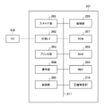
図2において、MFP101は、スキャナ部201、外部I/F202、プリンタ部203、操作部204、制御部205(印刷ジョブ実行手段)、給紙部206、ROM207、RAM208、HDD209、及び圧縮伸長部210を備える。スキャナ部201、外部I/F202、プリンタ部203、操作部204、制御部205、給紙部206、ROM207、RAM208、HDD209、及び圧縮伸長部210はシステムバス211を介して互いに接続されている。 In FIG. 2, the MFP 101 includes a scanner unit 201, an external I / F 202, a printer unit 203, an operation unit 204, a control unit 205 (print job execution means), a paper feed unit 206, a ROM 207, a RAM 208, an HDD 209, and a compression / decompression unit 210. To prepare for. The scanner unit 201, the external I / F 202, the printer unit 203, the operation unit 204, the control unit 205, the paper feed unit 206, the ROM 207, the RAM 208, the HDD 209, and the compression / expansion unit 210 are connected to each other via the system bus 211.

スキャナ部201は、載置された原稿を読み取って画像情報を取得し、上記画像情報を画像データに変換し、上記画像データをプリンタ部203やHDD209等に転送する。外部I/F202はネットワーク103に接続されたPC102等の通信装置とデータを送受信する。プリンタ部203は、PC102から受信した印刷データやスキャナ部201から転送された画像データに基づいて印刷を行う。操作部204は、MFP101のユーザインターフェースであり、図3に示すように、タッチパネル部301及びハードキー入力部302を備える。タッチパネル部301には操作画面が表示され、ユーザは上記操作画面によってジョブの投入やMFP101の設定変更を指示する。制御部205はMFP101全体の動作を統括的に制御する。例えば、制御部205はROM207に格納されたプログラムを実行して図5のソフトウェアモジュール500の各処理を行う。 The scanner unit 201 reads the mounted document, acquires image information, converts the image information into image data, and transfers the image data to the printer unit 203, HDD 209, or the like. The external I / F 202 transmits / receives data to / from a communication device such as a PC 102 connected to the network 103. The printer unit 203 prints based on the print data received from the PC 102 and the image data transferred from the scanner unit 201. The operation unit 204 is a user interface of the MFP 101, and includes a touch panel unit 301 and a hard key input unit 302 as shown in FIG. An operation screen is displayed on the touch panel unit 301, and the user instructs the user to submit a job or change the setting of the MFP 101 on the operation screen. The control unit 205 comprehensively controls the operation of the entire MFP 101. For example, the control unit 205 executes the program stored in the ROM 207 to perform each process of the software module 500 of FIG.

給紙部206は後述する図3の給紙カセット410,411、給紙デッキ412,413、及び手差しトレイ414といった複数の給紙装置を備える。給紙部206は複数の給紙装置のうち制御部205に指定された給紙装置から用紙を一枚ずつプリンタ部203へ搬送する。ROM207は制御部205によって実行されるプログラムやMFP101の設定情報等を記憶する。RAM208は制御部205の作業領域として、また、各データの一時格納領域として用いられる。HDD209は大容量の記憶装置であり、図示しないハードディスク及びハードディスクに対してデータの読み書きを行う駆動部等で構成される。HDD209はスキャナ部201によって生成された画像データを記憶する。また、HDD209はスプーラとして用いられ、PC102から受信した印刷データを記憶する。圧縮伸長部210は、JBIGやJPEG等といった圧縮方式により、RAM208やHDD209に記憶された画像データに対して圧縮処理及び伸長処理を施す。 The paper feed unit 206 includes a plurality of paper feed devices such as the paper feed cassettes 410 and 411, the paper feed decks 421 and 413, and the manual feed tray 414, which will be described later in FIG. The paper feeding unit 206 conveys paper one by one from the paper feeding device designated by the control unit 205 among the plurality of paper feeding devices to the printer unit 203. The ROM 207 stores a program executed by the control unit 205, setting information of the MFP 101, and the like. The RAM 208 is used as a work area of the control unit 205 and as a temporary storage area for each data. The HDD 209 is a large-capacity storage device, and is composed of a hard disk (not shown) and a drive unit that reads / writes data to / from the hard disk. The HDD 209 stores the image data generated by the scanner unit 201. Further, the HDD 209 is used as a spooler and stores the print data received from the PC 102. The compression / decompression unit 210 performs compression processing and decompression processing on the image data stored in the RAM 208 or HDD 209 by a compression method such as JBIG or JPEG.

図4は、図1のMFP101のハードウェアの構成を説明するための図である。図4(a)は、MFP101の断面図であり、図4(b)は、給紙デッキ412の概略図である。 FIG. 4 is a diagram for explaining the hardware configuration of the MFP 101 of FIG. 1. 4 (a) is a cross-sectional view of the MFP 101, and FIG. 4 (b) is a schematic view of the paper feed deck 412.

図4(a)において、MFP101では、自動原稿搬送装置(ADF)401が、原稿トレイ(不図示)の積載面にセットされた原稿束を1ページ目の原稿からページ順に原稿台ガラス上へ搬送する。スキャナ402は、原稿台ガラス上の原稿の画像を読み取り、読み取った画像をCCDによって画像データに変換する。その後、ポリゴンミラー等の回転多面鏡403が上記画像データを変調したレーザ光を、反射ミラーを介して感光ドラム404に照射する。これにより、感光ドラム404上に潜像が形成される。感光ドラム404上の潜像はトナーによって現像され、転写ドラム405上に貼り付けられた用紙にトナー像として転写される。この一連の画像形成処理がイエロー(Y)、マゼンタ(M)、シアン(C)、及びブラック(K)の順に実行され、上記用紙にはフルカラー画像が形成される。フルカラー画像が形成された転写ドラム405上の用紙は、分離爪406によって分離され、定着前搬送器407によって定着器408へ搬送される。定着器408はトナー像が転写された用紙上のトナーを、熱と圧力によって溶解させ、上記トナー像を用紙に定着させる。排紙フラッパ409は揺動軸(不図示)を中心に揺動可能に構成され、用紙の搬送方向を規定する。 In FIG. 4A, in the MFP 101, the automatic document transfer device (ADF) 401 transports a bundle of documents set on the loading surface of the document tray (not shown) onto the platen glass in page order from the first page of the original. do. The scanner 402 reads the image of the original on the platen glass and converts the read image into image data by the CCD. After that, a rotating multi-sided mirror 403 such as a polygon mirror irradiates the photosensitive drum 404 with a laser beam obtained by modulating the image data via the reflection mirror. As a result, a latent image is formed on the photosensitive drum 404. The latent image on the photosensitive drum 404 is developed by toner and transferred as a toner image to the paper attached on the transfer drum 405. This series of image forming processes is executed in the order of yellow (Y), magenta (M), cyan (C), and black (K), and a full-color image is formed on the above-mentioned paper. The paper on the transfer drum 405 on which the full-color image is formed is separated by the separation claw 406 and conveyed to the fixing device 408 by the pre-fixing carrier 407. The fuser 408 melts the toner on the paper on which the toner image is transferred by heat and pressure, and fixes the toner image on the paper. The paper ejection flapper 409 is configured to swing around a swing shaft (not shown), and defines a paper transport direction.

また、MFP101では、印刷に使用する用紙が給紙部206に収納されている。給紙部206は、複数の給紙装置、具体的に、給紙カセット410、411、給紙デッキ412、413、及び手差しトレイ414を備える。給紙部206では、大きさや厚さ等の種類が異なる用紙が、給紙カセット410、411、及び給紙デッキ412、413毎に区別して収納される。また、給紙部206では、手差しトレイ414にOHPシート等がセットされる。なお、本実施の形態では、給紙カセット410、411は同様の構成であり、以下では、一例として、給紙カセット410を用いてその構成を説明する。また、給紙デッキ412、413は同様の構成であり、以下では、一例として、給紙デッキ412を用いてその構成を説明する。 Further, in the MFP 101, the paper used for printing is stored in the paper feed unit 206. The paper feed unit 206 includes a plurality of paper feed devices, specifically, a paper feed cassette 410, 411, a paper feed deck 412, 413, and a manual feed tray 414. In the paper feed unit 206, papers of different sizes, thicknesses, and the like are separately stored in the paper feed cassettes 410, 411, and the paper feed decks 421 and 413. Further, in the paper feed unit 206, an OHP sheet or the like is set in the manual feed tray 414. In the present embodiment, the paper cassettes 410 and 411 have the same configuration, and the configuration will be described below using the paper cassette 410 as an example. Further, the paper feed decks 412 and 413 have the same configuration, and the configuration will be described below using the paper feed deck 412 as an example.

給紙カセット410は500枚程度の用紙を収納可能であり、図示しない非電子ロック式の開ボタン及び開閉センサを備える。ユーザが上記開ボタンを押下すると、給紙カセット410が開く。これにより、ユーザは給紙カセット410に用紙を補給する、若しくは他の種類の用紙に差し替えることが可能となる。給紙カセット410が開いたことを上記開閉センサが検知すると、この旨が制御部205に通知される。 The paper cassette 410 can store about 500 sheets of paper, and includes a non-electronic lock type open button and an open / close sensor (not shown). When the user presses the open button, the paper cassette 410 opens. This allows the user to replenish the paper cassette 410 with paper or replace it with another type of paper. When the open / close sensor detects that the paper cassette 410 has been opened, the control unit 205 is notified to that effect.

給紙デッキ412は5000枚程度の用紙を収納可能であり、図4(b)の開ボタン415を備える。開ボタン415は電子ロック式の操作ボタンである。給紙デッキ412では、ユーザが開ボタン415を押下し、且つ給紙デッキ412がロック状態でない場合のみ給紙デッキ412が開く。ユーザによる開ボタン415の押下を検知した際にこの旨が制御部205に通知される。 The paper feed deck 412 can store about 5,000 sheets of paper, and includes the open button 415 of FIG. 4 (b). The open button 415 is an electronic lock type operation button. In the paper feed deck 412, the paper feed deck 412 opens only when the user presses the open button 415 and the paper feed deck 412 is not in the locked state. When the user presses the open button 415, the control unit 205 is notified to that effect.

手差しトレイ414には不図示の用紙検出機構が設けられる。上記用紙検出機構により、手差しトレイ414に用紙がセットされたこと、若しくは手差しトレイ414から用紙が除去されたことが検知され、この旨が制御部205に通知される。 The manual feed tray 414 is provided with a paper detection mechanism (not shown). The paper detection mechanism detects that the paper has been loaded in the manual feed tray 414 or that the paper has been removed from the manual feed tray 414, and the control unit 205 is notified to that effect.

図5は、図1のMFP101のソフトウェアモジュール500の構成を概略的に示すブロック図である。 FIG. 5 is a block diagram schematically showing the configuration of the software module 500 of the MFP 101 of FIG.

図5において、ソフトウェアモジュール500は、印刷ジョブ検知部501、印刷処理部502、入力受付部503、表示部504、予約処理部505、ロック処理部506、及び開検知部507を備える。ソフトウェアモジュール500の各処理は、制御部205がROM207等に格納されたプログラムを実行することによって行われる。 In FIG. 5, the software module 500 includes a print job detection unit 501, a print processing unit 502, an input reception unit 503, a display unit 504, a reservation processing unit 505, a lock processing unit 506, and an open detection unit 507. Each process of the software module 500 is performed by the control unit 205 executing a program stored in the ROM 207 or the like.

印刷ジョブ検知部501は、PC102から印刷データを受信した際に上記印刷データをRAM208に格納する。また、印刷ジョブ検知部501は、上記印刷データに設定された投入先に基づいて上記印刷データに対応する印刷ジョブをプリントキュー及びホールドキューの何れかに投入する。印刷処理部502はプリンタ部203及び給紙部206を制御して用紙に印刷を行う。入力受付部503は操作部204によって受け付けたユーザ入力情報を制御部205に出力する。表示部504は操作部204における表示制御を行う。予約処理部505は給紙装置の予約及び予約の解除を制御する。本実施の形態では、印刷ジョブを実行する前に、上記印刷ジョブで使用する給紙装置を予約することが可能であり、予約された給紙装置は上記印刷ジョブの実行が完了するまで他の印刷ジョブで使用することができない。ロック処理部506は、電子ロック式の開ボタン415を備える給紙デッキ412,413をロック状態にして開ボタン415の操作を受け付けないように制御し、また、給紙デッキ412,413のロック状態を解除する。開検知部507は給紙部206の各給紙装置の開操作を検知すると、この旨を制御部205に通知する。 The print job detection unit 501 stores the print data in the RAM 208 when the print data is received from the PC 102. Further, the print job detection unit 501 inputs the print job corresponding to the print data to either the print queue or the hold queue based on the input destination set in the print data. The print processing unit 502 controls the printer unit 203 and the paper feed unit 206 to print on paper. The input receiving unit 503 outputs the user input information received by the operation unit 204 to the control unit 205. The display unit 504 controls the display on the operation unit 204. The reservation processing unit 505 controls the reservation of the paper feed device and the cancellation of the reservation. In the present embodiment, it is possible to reserve the paper feed device used in the print job before executing the print job, and the reserved paper feed device is used until the execution of the print job is completed. Cannot be used in print jobs. The lock processing unit 506 controls the paper feed decks 421 and 413 provided with the electronic lock type open button 415 so as not to accept the operation of the open button 415, and also locks the paper feed decks 421 and 413. To cancel. When the open detection unit 507 detects an open operation of each paper feed device of the paper feed unit 206, the open detection unit 507 notifies the control unit 205 to that effect.

次に、通信システム100において、印刷ジョブをホールドキューへ投入する指示が行われてから上記印刷ジョブが実行されるまでの処理について、図6~図20を用いて説明する。 Next, in the communication system 100, the process from the instruction to put the print job into the hold queue to the execution of the print job will be described with reference to FIGS. 6 to 20.

図6は、図1のPC102において印刷ジョブをホールドキューへ投入する指示が行われてからMFP101において上記印刷ジョブで使用する給紙装置の予約処理が行われるまでの処理の手順を示すシーケンス図である。 FIG. 6 is a sequence diagram showing a processing procedure from the instruction to put a print job into the hold queue in the PC 102 of FIG. 1 to the reservation processing of the paper feed device used in the print job in the MFP 101. be.

図6において、ユーザがPC102を操作して印刷ジョブをホールドキューへ投入する指示を行うと、PC102はホールドキューを投入先に設定した印刷データを生成する(ステップS101)。次いで、PC102は生成した印刷データをMFP101に送信する(ステップS102)。印刷データを受信したMFP101は、上記印刷データに対応する印刷ジョブをホールドキューに投入する(ステップS103)。その後、PC102からMFP101に移動したユーザが給紙部206に用紙を補給し、さらにユーザが操作部204においてプリントキューに投入された印刷ジョブの印刷予約指示を行うと、操作部204は印刷予約指示を受け付けた旨を制御部205に通知する(ステップS104)。また、操作部204はホールドキューに投入された印刷ジョブの一覧情報を表示し、上記一覧情報の中からユーザに選択された印刷ジョブ(以下、「選択印刷ジョブ」という。)を制御部205に通知する。選択印刷ジョブを通知された制御部205は予約可能な給紙装置を検索し(ステップS105)、上記予約可能な給紙装置の表示要求を操作部204に行う。操作部204は、選択印刷ジョブで使用する給紙装置の候補として上記予約可能な給紙装置を表示する(ステップS106)。その後、操作部204に表示された予約可能な給紙装置の中からユーザに選択された給紙装置を示す給紙装置番号を制御部205に通知する(ステップS107)。本実施の形態では、給紙装置番号「1」が給紙カセット410を示し、給紙装置番号「2」が給紙カセット411を示し、給紙装置番号「3」が給紙デッキ412を示すこととする。また、給紙装置番号「4」が給紙デッキ413を示し、給紙装置番号「5」が手差しトレイ414を示すこととする。操作部204から給紙装置番号を取得した制御部205は、選択印刷ジョブをプリントキューに投入し、さらに、取得した給紙装置番号が示す給紙装置の予約処理を行う(ステップS108)。 In FIG. 6, when the user operates the PC 102 to give an instruction to input a print job to the hold queue, the PC 102 generates print data in which the hold queue is set as the input destination (step S101). Next, the PC 102 transmits the generated print data to the MFP 101 (step S102). Upon receiving the print data, the MFP 101 puts the print job corresponding to the print data into the hold queue (step S103). After that, when the user who has moved from the PC 102 to the MFP 101 replenishes the paper feed unit 206 and the user gives a print reservation instruction for the print job put into the print queue in the operation unit 204, the operation unit 204 gives a print reservation instruction. Notifies the control unit 205 that the above is accepted (step S104). Further, the operation unit 204 displays the list information of the print jobs submitted to the hold queue, and the print job selected by the user from the above list information (hereinafter referred to as “selective print job”) is sent to the control unit 205. Notice. The control unit 205 notified of the selective print job searches for a reservable paper feed device (step S105), and makes a display request for the reservable paper feed device to the operation unit 204. The operation unit 204 displays the reserved paper feed device as a candidate for the paper feed device to be used in the selective print job (step S106). After that, the control unit 205 is notified of the paper feed device number indicating the paper feed device selected by the user from the reservable paper feed devices displayed on the operation unit 204 (step S107). In the present embodiment, the paper feed device number "1" indicates the paper feed cassette 410, the paper feed device number "2" indicates the paper feed cassette 411, and the paper feed device number "3" indicates the paper feed deck 412. I will do it. Further, the paper feed device number "4" indicates the paper feed deck 413, and the paper feed device number "5" indicates the manual feed tray 414. The control unit 205, which has acquired the paper feed device number from the operation unit 204, puts the selective print job into the print queue, and further performs the reservation process of the paper feed device indicated by the acquired paper feed device number (step S108).

図7は、図1のMFP101によって実行される第1の印刷予約受付処理の手順を示すフローチャートである。 FIG. 7 is a flowchart showing a procedure of the first print reservation acceptance process executed by the MFP 101 of FIG.

図7の処理は、制御部205がROM207等に格納されたプログラムを実行することによって行われ、操作部204においてホールドキューに投入された印刷ジョブの印刷予約指示を受け付けた際に実行される。 The process of FIG. 7 is performed by the control unit 205 executing the program stored in the ROM 207 or the like, and is executed when the operation unit 204 receives the print reservation instruction of the print job put into the hold queue.

図7において、まず、制御部205はホールドキューに投入された印刷ジョブの一覧情報を取得する。制御部205は取得した一覧情報に基づいて図8の選択画面801を操作部204に表示する(ステップS201)。選択画面801は、ホールドキューに投入された印刷ジョブを確認するための操作画面である。一覧802にはホールドキューに投入された印刷ジョブが表示される。選択画面801において、ユーザにより一覧802の中から、例えば、印刷ジョブCが選択された状態で予約ボタン803が押下されると(ステップS202でYES)、制御部205は予約可能な給紙装置を検索する(例えば、図6のステップS105参照)。具体的に、制御部205は予約可能な給紙装置が存在するか否かを図9(a)の管理テーブル901に基づいて判別する(ステップS203)。 In FIG. 7, first, the control unit 205 acquires the list information of the print jobs put into the hold queue. The control unit 205 displays the selection screen 801 of FIG. 8 on the operation unit 204 based on the acquired list information (step S201). The selection screen 801 is an operation screen for confirming the print job submitted to the hold queue. The print jobs submitted to the hold queue are displayed in the list 802. On the selection screen 801, for example, when the reservation button 803 is pressed while the print job C is selected from the list 802 by the user (YES in step S202), the control unit 205 selects a paper feed device that can be reserved. Search (see, for example, step S105 in FIG. 6). Specifically, the control unit 205 determines whether or not there is a reservable paper feed device based on the management table 901 of FIG. 9A (step S203).

管理テーブル901は、印刷ジョブの実行に関する情報を管理し、ジョブ実行順序902、ジョブ名903、番号904、予約状態905、ロック機構906、及びジョブ実行可否907を備える。管理テーブル901には、プリントキューに投入された印刷ジョブ、つまり、ユーザに即座に実行することを指示された印刷ジョブの実行に関する情報が登録される。本実施の形態では、投入先がプリントキューに設定された印刷ジョブ、及びホールドキューに投入された印刷ジョブであって且つ操作部204においてユーザによる印刷開始指示を受け付けた印刷ジョブが、プリントキューに投入される。ジョブ実行順序902は印刷ジョブの実行順を示す。本実施の形態では、プリントキューに投入された順がそのまま実行順として設定される。 The management table 901 manages information related to the execution of print jobs, and includes a job execution order 902, a job name 903, a number 904, a reservation state 905, a lock mechanism 906, and a job execution enable / disable 907. In the management table 901, information regarding the execution of the print job put into the print queue, that is, the print job instructed to be executed immediately by the user is registered. In the present embodiment, the print job whose input destination is set to the print queue and the print job that has been input to the hold queue and whose operation unit 204 has received the print start instruction by the user are transferred to the print queue. It is thrown in. The job execution order 902 indicates the execution order of the print job. In the present embodiment, the order of being put into the print queue is set as the execution order as it is.

ジョブ名903はプリントキューに投入された印刷ジョブを示す名称である。番号904には登録された印刷ジョブが使用する給紙装置を示す給紙装置番号が設定される。予約状態905には番号904が示す給紙装置が予約済みであるか否かを示す情報が設定される。ロック機構906には番号904が示す給紙装置が電子ロック式の開ボタン415のようなロック機構を備えているか否かを示す情報が設定される。 The job name 903 is a name indicating a print job submitted to the print queue. A paper feed device number indicating a paper feed device used by the registered print job is set in the number 904. Information indicating whether or not the paper feeding device indicated by the number 904 is reserved is set in the reserved state 905. Information indicating whether or not the paper feed device indicated by the number 904 has a lock mechanism such as an electronic lock type open button 415 is set in the lock mechanism 906.

ジョブ実行可否907には登録された印刷ジョブが実行可能な状態であるか否かを示す情報が設定される。ジョブ実行可否907には、通常、実行可能な状態であることを示す「可」が設定されるが、給紙装置の予約が解除された印刷ジョブに対して実行不可能な状態であることを示す「不可」が設定される。ステップS203では、例えば、管理テーブル901において、図9(a)に示すように、給紙部206の一部の給紙装置の給紙装置番号のみが登録されている場合、制御部205は予約可能な給紙装置が存在すると判別する。一方、管理テーブル901において、図9(b)に示すように、給紙部206の全ての給紙装置の給紙装置番号が登録されている場合、制御部205は予約可能な給紙装置が存在しないと判別する。 Information indicating whether or not the registered print job can be executed is set in the job execution enable / disable 907. The job execution enable / disable 907 is normally set to "OK" indicating that the print job can be executed, but the print job whose reservation of the paper feed device has been canceled cannot be executed. The indicated "impossible" is set. In step S203, for example, in the management table 901, as shown in FIG. 9A, when only the paper feed device numbers of some of the paper feed devices of the paper feed unit 206 are registered, the control unit 205 reserves. Determine if there is a possible paper feed device. On the other hand, in the management table 901, as shown in FIG. 9B, when the paper feed device numbers of all the paper feed devices of the paper feed unit 206 are registered, the control unit 205 has a paper feed device that can be reserved. Determine that it does not exist.

ステップS203の判別の結果、予約可能な給紙装置が存在するとき、制御部205は選択印刷ジョブCで使用する給紙装置を予約するための図10の予約画面1001を操作部204に表示する(ステップS204)(例えば、図6のステップS106参照)。予約画面1001には、給紙部206の給紙装置のうち、予約可能な給紙装置のみが選択可能に表示される。例えば、図9(a)に示すように、管理テーブル901に給紙装置番号「2」、「3」が登録されている場合、予約画面1001では、予約可能な給紙装置として給紙装置番号「1」、「4」、「5」が選択可能に表示される。予約画面1001において、ユーザによる給紙装置番号の選択操作を受け付けると(ステップS205)、制御部205は選択画面801において選択印刷ジョブをプリントキューに投入する。 As a result of the determination in step S203, when there is a paper feed device that can be reserved, the control unit 205 displays the reservation screen 1001 of FIG. 10 for reserving the paper feed device to be used in the selective print job C on the operation unit 204. (Step S204) (see, for example, step S106 in FIG. 6). On the reservation screen 1001, only the paper feed devices that can be reserved are selectably displayed from the paper feed devices of the paper feed unit 206. For example, as shown in FIG. 9A, when the paper feed device numbers “2” and “3” are registered in the management table 901, the paper feed device number is reserved as a paper feed device on the reservation screen 1001. "1", "4", and "5" are displayed in a selectable manner. When the user accepts the selection operation of the paper feed device number on the reservation screen 1001 (step S205), the control unit 205 puts the selection print job into the print queue on the selection screen 801.

次いで、制御部205は予約画面1001において選択された給紙装置番号の給紙装置の予約処理を行う(ステップS206)。例えば、予約画面1001において給紙装置番号「1」の操作ボタン1002が選択された場合、ステップS206において制御部205は印刷ジョブCの給紙装置の予約処理を行う。印刷ジョブCの給紙装置の予約処理では、制御部205は、管理テーブル901に印刷ジョブCに関する情報を登録する。印刷ジョブCに関する情報として、例えば、図9(b)の管理テーブル908のように、番号904に給紙装置番号「1」が設定され、予約状態905に「予約済み」が設定され、ジョブ実行可否に「可」が設定される。これにより、印刷ジョブCの実行が完了するまで、給紙装置番号「1」に対応する給紙カセット410が印刷ジョブC以外の他のジョブで使用できなくなる。その後、制御部205は本処理を終了する。 Next, the control unit 205 performs a reservation process for the paper feed device of the paper feed device number selected on the reservation screen 1001 (step S206). For example, when the operation button 1002 of the paper feed device number “1” is selected on the reservation screen 1001, the control unit 205 performs the reservation process of the paper feed device of the print job C in step S206. In the reservation process of the paper feed device of the print job C, the control unit 205 registers the information about the print job C in the management table 901. As information about the print job C, for example, as shown in the management table 908 of FIG. 9B, the paper feed device number "1" is set in the number 904, "reserved" is set in the reserved state 905, and the job is executed. "Yes" is set for Yes / No. As a result, the paper cassette 410 corresponding to the paper feed device number "1" cannot be used by jobs other than the print job C until the execution of the print job C is completed. After that, the control unit 205 ends this process.

ステップS203の判別の結果、予約可能な給紙装置が存在しないとき、制御部205は各給紙装置の予約が解除されるまでの予測時間(以下、「予約解除予測時間」という。)を算出する。ここで、定着器408がトナーを用紙に定着させる定着処理の実行時間は、用紙の坪量に応じて異なり、坪量が多くなる程上記実行時間は長くなる。本実施の形態では、定着処理の実行時間から導出される用紙の種類毎の印刷速度がRAM208に予め保持され、各給紙装置に収納された用紙の種類の印刷速度に基づいて各給紙装置を使用する印刷ジョブの印刷時間を算出する。印刷ジョブの印刷時間を計算するために、制御部205は、プリントキューに投入されている全ての印刷ジョブを解析し、各印刷ジョブの印刷枚数と用紙の種類を取得する。また、制御部205は取得した各印刷ジョブの用紙の種類に対応する印刷速度をRAM208から取得する。制御部205は印刷速度及び印刷枚数を掛け合わせて各印刷ジョブの印刷時間を算出し、算出した印刷時間から各給紙装置の予約解除予測時間を算出する。例えば、図9(c)の管理テーブル909において、ジョブ実行順序902が「1」である印刷ジョブAの印刷枚数を60枚とし、且つ印刷ジョブAで使用する用紙の種別に対する印刷速度が60ppm(pageper minute)とする。このとき、印刷ジョブAの印刷時間は、60(枚)×(1/60)(分/枚)=1(分)となり、印刷ジョブAで使用する給紙装置番号「2」に対応する給紙カセット411の予約解除予測時間が1(分)となる。 As a result of the determination in step S203, when there is no reservable paper feed device, the control unit 205 calculates the estimated time until the reservation of each paper feed device is canceled (hereinafter, referred to as "reservation cancellation predicted time"). do. Here, the execution time of the fixing process for fixing the toner to the paper by the fixing device 408 differs depending on the basis weight of the paper, and the larger the basis weight, the longer the execution time. In the present embodiment, the printing speed for each type of paper derived from the execution time of the fixing process is held in advance in the RAM 208, and each paper feeding device is based on the printing speed of the type of paper stored in each paper feeding device. Calculate the print time for print jobs that use. In order to calculate the print time of a print job, the control unit 205 analyzes all the print jobs put in the print queue and acquires the number of prints and the type of paper for each print job. Further, the control unit 205 acquires the print speed corresponding to the type of paper of each acquired print job from the RAM 208. The control unit 205 calculates the print time of each print job by multiplying the print speed and the number of prints, and calculates the reservation cancellation predicted time of each paper feed device from the calculated print time. For example, in the management table 909 of FIG. 9C, the number of prints of the print job A in which the job execution order 902 is "1" is set to 60, and the print speed for the type of paper used in the print job A is 60 ppm (. Pageper print). At this time, the print time of the print job A is 60 (sheets) × (1/60) (minutes / sheet) = 1 (minutes), and the feed corresponding to the paper feed device number “2” used in the print job A is supplied. The estimated time for canceling the reservation of the paper cassette 411 is 1 (minute).

また、印刷ジョブAの次に実行される印刷ジョブBの印刷枚数を30枚とし、且つジョブBで使用する用紙の種別に対する印刷速度が30ppmとする。このとき、印刷ジョブBの印刷時間は、30(枚)×(1/30)(分/枚)=1(分)となる。この算出結果に、印刷ジョブAの印刷時間1(分)を加えた2(分)が印刷ジョブBで使用する給紙装置番号「3」に対応する給紙デッキ412の予約解除予測時間となる。同様に印刷ジョブC,D,Eで使用する各給紙装置の予約解除予測時間が算出される。制御部205は算出した結果に基づいて図11(a)の通知画面1101(予測時間通知手段)を操作部204に表示する(ステップS207)。通知画面1101は、給紙部206の全ての給紙装置が予約状態である旨のメッセージ、及び各給紙装置の予約解除予測時間を含む。なお、本実施の形態では、管理テーブル901のジョブ実行可否907が「不可」に設定されている印刷ジョブは操作部204においてユーザによる印刷開始指示を受け付けないと実行されない。このため、上記印刷ジョブに使用する給紙装置、及び上記印刷ジョブ以降の実行順の印刷ジョブに使用する給紙装置において、予約解除予測時間を算出することができない。例えば、管理テーブル909において、印刷ジョブDのジョブ実行可否907が“不可”である場合、印刷ジョブDに使用される給紙装置番号「1」に対応する給紙カセット410、及び印刷ジョブD以降の実行順の印刷ジョブEに使用する給紙装置番号「5」に対応する手差しトレイ414において、制御部205は予約解除予測時間を算出できない。このようなとき、制御部205は、ステップS207において図11(b)の通知画面1102(予測時間通知手段)を操作部204に表示しても良い。その後、制御部205は本処理を終了する。 Further, the number of prints of the print job B executed next to the print job A is set to 30, and the printing speed for the type of paper used in the job B is set to 30 ppm. At this time, the print time of the print job B is 30 (sheets) × (1/30) (minutes / sheet) = 1 (minutes). 2 (minutes), which is the sum of this calculation result and the print time 1 (minutes) of the print job A, is the estimated time for canceling the reservation of the paper feed deck 412 corresponding to the paper feed device number "3" used in the print job B. .. Similarly, the estimated time for canceling the reservation of each paper feed device used in the print jobs C, D, and E is calculated. The control unit 205 displays the notification screen 1101 (estimated time notification means) of FIG. 11A on the operation unit 204 based on the calculated result (step S207). The notification screen 1101 includes a message to the effect that all the paper feeding devices of the paper feeding unit 206 are in the reserved state, and the estimated time for canceling the reservation of each paper feeding device. In this embodiment, the print job in which the job execution enable / disable 907 of the management table 901 is set to "impossible" is not executed unless the operation unit 204 receives the print start instruction by the user. Therefore, it is not possible to calculate the reservation cancellation estimated time in the paper feed device used for the print job and the paper feed device used for the print job in the execution order after the print job. For example, in the management table 909, when the job execution enable / disable 907 of the print job D is "impossible", the paper feed cassette 410 corresponding to the paper feed device number "1" used for the print job D, and the print job D and later. In the manual feed tray 414 corresponding to the paper feed device number "5" used for the print job E in the execution order of the above, the control unit 205 cannot calculate the reservation cancellation predicted time. In such a case, the control unit 205 may display the notification screen 1102 (predicted time notification means) of FIG. 11B on the operation unit 204 in step S207. After that, the control unit 205 ends this process.

図12は、図1のMFP101において予約された給紙装置の開操作を受け付けた際の処理の手順を示すシーケンス図である。 FIG. 12 is a sequence diagram showing a processing procedure when an opening operation of the reserved paper feeding device is accepted in the MFP 101 of FIG. 1.

図12の処理は、図7の処理の実行を完了した後に実行される。図12の処理では、一例として、図7の処理において給紙装置番号「3」に対応する給紙デッキ412が印刷ジョブBの給紙装置として予約され、また、給紙装置番号「1」に対応する給紙カセット410が印刷ジョブDの給紙装置として予約されていることを前提とする。このとき、電子ロック式の開ボタン415を備える給紙デッキ412はロック状態となり、印刷ジョブBの投入指示を行ったユーザのみが給紙デッキ412を開くことが可能となる。印刷ジョブBの投入指示を行ったユーザであるか否かは、例えば、MFP101にログインした際に入力されたユーザIDに基づいて判別される。 The process of FIG. 12 is executed after the execution of the process of FIG. 7 is completed. In the process of FIG. 12, as an example, in the process of FIG. 7, the paper feed deck 412 corresponding to the paper feed device number “3” is reserved as the paper feed device of the print job B, and is set to the paper feed device number “1”. It is assumed that the corresponding paper cassette 410 is reserved as the paper feed device for print job D. At this time, the paper feed deck 412 provided with the electronic lock type open button 415 is locked, and only the user who has instructed to input the print job B can open the paper feed deck 412. Whether or not the user has given the instruction to submit the print job B is determined based on, for example, the user ID input when logging in to the MFP 101.

図12において、印刷ジョブBの投入指示を行ったユーザ以外の他のユーザが給紙装置番号「3」に対応する給紙デッキ412の開ボタン415を押下すると、給紙部206は給紙デッキ412において他のユーザによる開操作を検知する(ステップS301)。給紙部206は給紙デッキ412を開けず、給紙デッキ412において他のユーザによる開操作を検知した旨を制御部205に通知する(ステップS302)。上記通知を受信した制御部205は、給紙デッキ412が予約済みであることを検知すると(ステップS303)、予約通知画面の表示要求を操作部204に行う(ステップS304)。上記表示要求を受け付けた操作部204は、給紙デッキ412が予約状態である旨を示す予約通知画面を表示する。その後、操作部204において上記他のユーザによる給紙デッキ412のロック解除指示を受け付けると、操作部204は、給紙デッキ412のロック解除指示が行われたことを制御部205に通知する(ステップS305)。上記通知を受信した制御部205は給紙部206に給紙デッキ412のロック状態の解除要求を行う(ステップS306)。上記解除要求を受け付けた給紙部206は給紙デッキ412のロック状態を解除し、給紙デッキ412を開ける(ステップS307)。その後、制御部205は給紙デッキ412の予約を解除する(ステップS308)。具体的に、制御部205は、図13(a)の管理テーブル1301のように、印刷ジョブBの予約状態905を「予約解除」に設定し、また、印刷ジョブBのジョブ実行可否907を「不可」に設定する。 In FIG. 12, when a user other than the user who has instructed to input the print job B presses the open button 415 of the paper feed deck 412 corresponding to the paper feed device number “3”, the paper feed unit 206 moves to the paper feed deck. In 412, an open operation by another user is detected (step S301). The paper feed unit 206 does not open the paper feed deck 412, and notifies the control unit 205 that the paper feed deck 412 has detected an open operation by another user (step S302). When the control unit 205 that has received the above notification detects that the paper feed deck 412 is reserved (step S303), the control unit 205 requests the operation unit 204 to display the reservation notification screen (step S304). The operation unit 204 that has received the display request displays a reservation notification screen indicating that the paper feed deck 412 is in the reserved state. After that, when the operation unit 204 receives the unlock instruction of the paper feed deck 412 by the other user, the operation unit 204 notifies the control unit 205 that the unlock instruction of the paper feed deck 412 has been performed (step). S305). Upon receiving the above notification, the control unit 205 requests the paper feed unit 206 to release the locked state of the paper feed deck 412 (step S306). Upon receiving the release request, the paper feed unit 206 releases the locked state of the paper feed deck 412 and opens the paper feed deck 412 (step S307). After that, the control unit 205 cancels the reservation of the paper feed deck 412 (step S308). Specifically, the control unit 205 sets the reservation status 905 of the print job B to "cancel the reservation" and sets the job execution possibility 907 of the print job B to "cancellation of reservation" as shown in the management table 1301 of FIG. 13 (a). Set to "No".

また、印刷ジョブDの投入指示を行ったユーザ以外の他のユーザが給紙装置番号「1」に対応する給紙カセット410の開ボタン(不図示)を押下すると、給紙部206は給紙カセット410において他のユーザによる開操作を検知する(ステップS309)。給紙部206は給紙デッキ412を開け、給紙カセット410において他のユーザによる開操作を検知した旨を制御部205に通知する(ステップS310)。上記通知を受信した制御部205は、給紙カセット410が予約済みであることを検知すると(ステップS311)、予約通知画面の表示要求を操作部204に行う(ステップS312)。上記表示要求を受け付けた操作部204は、給紙カセット410が予約状態である旨を示す予約通知画面を表示する。また、制御部205は給紙カセット410の予約を解除する(ステップS313)。具体的に、制御部205は、図13(b)の管理テーブル1302のように、印刷ジョブDの予約状態905を「予約解除」に設定し、また、印刷ジョブDのジョブ実行可否907を「不可」に設定する。 Further, when a user other than the user who has instructed to input the print job D presses the open button (not shown) of the paper cassette 410 corresponding to the paper feed device number "1", the paper feed unit 206 feeds paper. The opening operation by another user is detected in the cassette 410 (step S309). The paper feed unit 206 opens the paper feed deck 412 and notifies the control unit 205 that the paper feed cassette 410 has detected an open operation by another user (step S310). When the control unit 205 that has received the above notification detects that the paper cassette 410 is reserved (step S311), the control unit 205 requests the operation unit 204 to display the reservation notification screen (step S312). The operation unit 204 that has received the display request displays a reservation notification screen indicating that the paper cassette 410 is in the reserved state. Further, the control unit 205 cancels the reservation of the paper feed cassette 410 (step S313). Specifically, the control unit 205 sets the reservation status 905 of the print job D to "cancel the reservation" and sets the job execution possibility 907 of the print job D to "cancellation of reservation" as shown in the management table 1302 of FIG. 13B. Set to "No".

図14は、図1のMFP101によって実行されるロック制御処理の手順を示すフローチャートである。 FIG. 14 is a flowchart showing the procedure of the lock control process executed by the MFP 101 of FIG.

図14の処理も、制御部205がROM207等に格納されたプログラムを実行することによって行われる。図14の処理は、他のユーザによる給紙カセット410,411及び給紙デッキ412,413の何れかの開操作、又は他のユーザによる手差しトレイ414における用紙やシート等の記録部材のセットや上記記録部材の除去等の操作といった他のユーザによる給紙装置関連操作を検知した際に実行される。 The process of FIG. 14 is also performed by the control unit 205 executing the program stored in the ROM 207 or the like. The process of FIG. 14 is an operation of opening any of the paper cassettes 410, 411 and the paper feed decks 421 and 413 by another user, a setting of recording members such as paper and sheets in the manual feed tray 414 by another user, and the above. It is executed when an operation related to the paper feed device by another user such as an operation such as removal of a recording member is detected.

図14において、制御部205は他のユーザによる給紙装置関連操作を検知すると、他のユーザによる給紙装置関連操作が検知された給紙装置(以下、「操作検知給紙装置」)がロック機構を搭載するか否かを判別する(ステップS401)。ステップS401では、例えば、操作検知給紙装置が電子ロック式の開ボタン415を備える給紙デッキ412,413である場合、制御部205は操作検知給紙装置がロック機構を搭載すると判別する。一方、操作検知給紙装置が電子ロック式の開ボタン415を備えない給紙カセット410,411及び手差しトレイ414である場合、制御部205は操作検知給紙装置がロック機構を搭載しないと判別する。 In FIG. 14, when the control unit 205 detects a paper feed device-related operation by another user, the paper feed device (hereinafter, “operation detection paper feed device”) in which the paper feed device-related operation by another user is detected is locked. It is determined whether or not the mechanism is mounted (step S401). In step S401, for example, when the operation detection paper feed device is the paper feed decks 421 and 413 provided with the electronic lock type open button 415, the control unit 205 determines that the operation detection paper feed device is equipped with the lock mechanism. On the other hand, when the operation detection paper feed device is a paper feed cassette 410, 411 and a manual feed tray 414 not equipped with an electronic lock type open button 415, the control unit 205 determines that the operation detection paper feed device does not have a lock mechanism. ..

ステップS401の判別の結果、操作検知給紙装置がロック機構を搭載するとき、制御部205は操作検知給紙装置が予約済みであるか否かを判別する(ステップS402)。 As a result of the determination in step S401, when the operation detection paper feed device is equipped with the lock mechanism, the control unit 205 determines whether or not the operation detection paper feed device is reserved (step S402).

ステップS402の判別の結果、操作検知給紙装置が予約済みであるとき、制御部205は、操作検知給紙装置を開けず、図15(a)の予約通知画面1501(警告手段)を操作部204に表示する(ステップS403)。予約通知画面1501には、操作検知給紙装置が予約済みである旨を示すメッセージ1502、解除ボタン1503、及びキャンセルボタン1504を備える。解除ボタン1503は操作検知給紙装置のロック状態を解除するための操作ボタンである。キャンセルボタン1504は予約通知画面1501を閉じるための操作ボタンである。予約通知画面1501において解除ボタン1503及びキャンセルボタン1504の何れかの操作ボタンがユーザに押下されると(ステップS404でYES)、制御部205は押下された操作ボタンが解除ボタン1503及びキャンセルボタン1504の何れであるかを判別する(ステップS405)。 As a result of the determination in step S402, when the operation detection paper feed device is reserved, the control unit 205 does not open the operation detection paper feed device and displays the reservation notification screen 1501 (warning means) of FIG. 15A. It is displayed on 204 (step S403). The reservation notification screen 1501 includes a message 1502 indicating that the operation detection paper feeding device is reserved, a release button 1503, and a cancel button 1504. The release button 1503 is an operation button for releasing the locked state of the operation detection paper feed device. The cancel button 1504 is an operation button for closing the reservation notification screen 1501. When any of the operation buttons of the release button 1503 and the cancel button 1504 is pressed by the user on the reservation notification screen 1501 (YES in step S404), the pressed operation button of the control unit 205 is the release button 1503 and the cancel button 1504. Which is determined (step S405).

ステップS405の判別の結果、押下された操作ボタンが解除ボタン1503であるとき、制御部205は操作検知給紙装置のロック状態を解除し、操作検知給紙装置を開ける(ステップS406)(例えば、図12のステップS307参照)。次いで、制御部205は操作検知給紙装置の予約を解除し(ステップS407)(例えば、図12のステップS308参照)、本処理を終了する。 As a result of the determination in step S405, when the pressed operation button is the release button 1503, the control unit 205 releases the locked state of the operation detection paper feed device and opens the operation detection paper feed device (step S406, for example). See step S307 in FIG. 12). Next, the control unit 205 cancels the reservation of the operation detection paper feed device (step S407) (see, for example, step S308 in FIG. 12), and ends this process.

ステップS401の判別の結果、操作検知給紙装置がロック機構を搭載しないとき、制御部205は操作検知給紙装置が予約済みであるか否かを管理テーブル901に基づいて判別する(ステップS408)。 As a result of the determination in step S401, when the operation detection paper feed device is not equipped with the lock mechanism, the control unit 205 determines whether or not the operation detection paper feed device is reserved based on the management table 901 (step S408). ..

ステップS408の判別の結果、操作検知給紙装置が予約済みであるとき、制御部205は操作検知給紙装置が予約済みである旨を示す図15(b)の予約通知画面1505(警告手段)を操作部204に表示する(ステップS409)。また、制御部205は操作検知給紙装置の予約を解除し(例えば、図12のステップS313参照)、本処理を終了する。 As a result of the determination in step S408, when the operation detection paper feed device is reserved, the control unit 205 indicates that the operation detection paper feed device is reserved, the reservation notification screen 1505 (warning means) of FIG. 15 (b). Is displayed on the operation unit 204 (step S409). Further, the control unit 205 cancels the reservation of the operation detection paper feed device (see, for example, step S313 in FIG. 12), and ends this process.

ステップS402,S408の判別の結果、操作検知給紙装置が予約済みでないとき、又はステップS405の判別の結果、押下された操作ボタンがキャンセルボタン1504であるとき、制御部205は本処理を終了する。 When the operation detection paper feed device is not reserved as a result of the determination in steps S402 and S408, or when the pressed operation button is the cancel button 1504 as a result of the determination in step S405, the control unit 205 ends this process. ..

図16及び図18は、図1のMFP101において給紙装置が予約された印刷ジョブ及び給紙装置の予約が解除された印刷ジョブを実行する際の処理の手順を示すシーケンス図である。図16及び図18の処理では、一例として、管理テーブル1302のように、印刷ジョブAで使用する給紙装置として給紙装置番号「2」の給紙カセット411が予約され、また、印刷ジョブAの次に実行される印刷ジョブBで使用する給紙装置の予約が解除されていることを前提とする。 16 and 18 are sequence diagrams showing a procedure for executing a print job in which the paper feed device is reserved and a print job in which the paper feed device is canceled in the MFP 101 of FIG. 1. In the processes of FIGS. 16 and 18, as an example, as in the management table 1302, the paper cassette 411 of the paper feed device number “2” is reserved as the paper feed device used in the print job A, and the print job A is also reserved. It is assumed that the reservation of the paper feed device used in the print job B to be executed next is canceled.

図16及び図18において、まず、制御部205は、プリントキューにおいて印刷ジョブAを検知すると(ステップS501)、管理テーブル1302に基づいて印刷ジョブAがジョブ実行可能であるか否かを判別する。印刷ジョブAがジョブ実行可能であると(ステップS502)、制御部205は、給紙部206に給紙開始要求を行い、また、プリンタ部203に印刷開始要求を行う。給紙開始要求を受け付けた給紙部206は印刷ジョブAに関する給紙を開始する(ステップS503)。また、印刷開始要求を受け付けたプリンタ部203は印刷ジョブAに関する印刷を開始する(ステップS504)。印刷ジョブAの実行を完了すると、制御部205は、管理テーブル1302から印刷ジョブAに関する情報を削除し、ジョブ実行順序902を更新する(例えば、図17の管理テーブル1701参照)。 In FIGS. 16 and 18, when the control unit 205 first detects the print job A in the print queue (step S501), the control unit 205 determines whether or not the print job A can execute the job based on the management table 1302. When the print job A can execute the job (step S502), the control unit 205 makes a paper feed start request to the paper feed unit 206, and also makes a print start request to the printer unit 203. The paper feed unit 206 that has received the paper feed start request starts paper feed for the print job A (step S503). Further, the printer unit 203 that has received the print start request starts printing related to the print job A (step S504). When the execution of the print job A is completed, the control unit 205 deletes the information about the print job A from the management table 1302 and updates the job execution order 902 (see, for example, the management table 1701 in FIG. 17).

次いで、制御部205はプリントキューにおいて印刷ジョブBを検知すると(ステップS505)、管理テーブル1701に基づいて印刷ジョブBがジョブ実行可能であるか否かを判別する。印刷ジョブBがジョブ実行不可能であると(ステップS506)、制御部205は、操作部204に一時停止画面を表示し(ステップS507)、ユーザに給紙装置の用紙を確認させる。次いで、操作部204においてユーザによる印刷再開指示を受け付けると、操作部204はこの旨を制御部205に通知する。上記通知を受信した制御部205は、給紙部206に給紙開始要求を行い、また、プリンタ部203に印刷開始要求を行う。給紙開始要求を受け付けた給紙部206は印刷ジョブBに関する給紙を開始する(ステップS508)。また、印刷開始要求を受け付けたプリンタ部203は印刷ジョブBに関する印刷を開始する(ステップS509)。 Next, when the control unit 205 detects the print job B in the print queue (step S505), the control unit 205 determines whether or not the print job B can execute the job based on the management table 1701. When the print job B cannot execute the job (step S506), the control unit 205 displays a pause screen on the operation unit 204 (step S507), and causes the user to check the paper of the paper feed device. Next, when the operation unit 204 receives the print restart instruction by the user, the operation unit 204 notifies the control unit 205 to that effect. Upon receiving the above notification, the control unit 205 makes a paper feed start request to the paper feed unit 206, and also makes a print start request to the printer unit 203. The paper feed unit 206 that has received the paper feed start request starts paper feed for print job B (step S508). Further, the printer unit 203 that has received the print start request starts printing related to the print job B (step S509).

図19は、図1のMFP101によって実行される印刷制御処理の手順を示すフローチャートである。 FIG. 19 is a flowchart showing a procedure of print control processing executed by the MFP 101 of FIG.

図19の処理も、制御部205がROM207等に格納されたプログラムを実行することによって行われる。図19の処理は、プリントキューにおいて印刷ジョブが検知された際に実行される。 The process of FIG. 19 is also performed by the control unit 205 executing the program stored in the ROM 207 or the like. The process of FIG. 19 is executed when a print job is detected in the print queue.

図19において、プリントキューにおいて印刷ジョブが検知されると(ステップS601でYES)、制御部205はプリントキューへの投入順が先頭の印刷ジョブ(以下、「先頭印刷ジョブ」という。)がジョブ実行可能であるか否かを判別する(ステップS602)。ステップS602では、例えば、制御部205は、管理テーブル1302の先頭印刷ジョブAのように、ジョブ実行可否907が「可」である先頭印刷ジョブをジョブ実行可能であると判別する。一方、制御部205は、管理テーブル1701の先頭印刷ジョブBのように、ジョブ実行可否907が「不可」である先頭印刷ジョブをジョブ実行不可能であると判別する。 In FIG. 19, when a print job is detected in the print queue (YES in step S601), the control unit 205 executes the job for the print job whose input order to the print queue is first (hereinafter, referred to as “first print job”). It is determined whether or not it is possible (step S602). In step S602, for example, the control unit 205 determines that the head print job whose job execution enable / disable 907 is "possible" can be executed, such as the head print job A of the management table 1302. On the other hand, the control unit 205 determines that the job cannot be executed for the first print job whose job execution enable / disable 907 is "impossible", such as the first print job B in the management table 1701.

ステップS602の判別の結果、先頭印刷ジョブがジョブ実行可能であるとき(例えば、図16のステップS502参照)、制御部205は給紙部206に給紙開始要求を行う。これにより、給紙部206が先頭印刷ジョブに関する給紙を開始する(例えば、図16のステップS503を参照)。また、制御部205はプリンタ部203に印刷開始要求を行う(ステップS603)。これにより、プリンタ部203が先頭印刷ジョブに関する印刷を開始する(例えば、図16のステップS504を参照)。先頭印刷ジョブの実行を完了すると、制御部205は管理テーブル901から先頭印刷ジョブに関する情報を削除し、ステップS601の処理に戻る。 As a result of the determination in step S602, when the first print job can be executed (see, for example, step S502 in FIG. 16), the control unit 205 makes a paper feed start request to the paper feed unit 206. As a result, the paper feed unit 206 starts paper feed for the first print job (see, for example, step S503 in FIG. 16). Further, the control unit 205 requests the printer unit 203 to start printing (step S603). As a result, the printer unit 203 starts printing related to the first print job (see, for example, step S504 in FIG. 16). When the execution of the first print job is completed, the control unit 205 deletes the information about the first print job from the management table 901 and returns to the process of step S601.

ステップS602の判別の結果、先頭印刷ジョブがジョブ実行可能であるとき(例えば、図16のステップS506参照)、制御部205は予約可能な給紙装置番号を特定する。例えば、管理テーブル1701の登録状況において、制御部205は管理テーブル1701において「予約済み」が登録された給紙装置番号以外の給紙装置番号「1」,「2」,「3」を予約可能な給紙装置番号として特定する。次いで、制御部205は図20の一時停止画面2001を操作部204に表示する(ステップS604)。一時停止画面2001には、給紙装置番号1~5のうち特定した給紙装置番号を示す操作ボタンのみが選択可能に表示される。次いで、制御部205は一時停止画面2001において印刷再開指示が行われたか否かを判別する(ステップS605)。ステップS605では、例えば、一時停止画面2001において、特定した給紙装置番号を示す操作ボタン2002が選択された状態でOKボタン2003が押下された場合、制御部205は一時停止画面2001において印刷再開指示が行われたと判別する。一方、一時停止画面2001において、キャンセルボタン2004が選択された場合、制御部205は一時停止画面2001において印刷再開指示が行われないと判別する。 As a result of the determination in step S602, when the first print job is job-executable (see, for example, step S506 in FIG. 16), the control unit 205 specifies a reservable paper feed device number. For example, in the registration status of the management table 1701, the control unit 205 can reserve the paper feed device numbers "1", "2", and "3" other than the paper feed device numbers in which "reserved" is registered in the management table 1701. Specify as a paper feed device number. Next, the control unit 205 displays the pause screen 2001 of FIG. 20 on the operation unit 204 (step S604). On the pause screen 2001, only the operation button indicating the specified paper feed device number among the paper feed device numbers 1 to 5 is displayed so as to be selectable. Next, the control unit 205 determines whether or not the print restart instruction has been given on the pause screen 2001 (step S605). In step S605, for example, when the OK button 2003 is pressed while the operation button 2002 indicating the specified paper feed device number is selected on the pause screen 2001, the control unit 205 gives an instruction to resume printing on the pause screen 2001. Is determined to have been performed. On the other hand, when the cancel button 2004 is selected on the pause screen 2001, the control unit 205 determines that the print restart instruction is not given on the pause screen 2001.

ステップS605の判別の結果、一時停止画面2001において印刷再開指示が行われたとき、制御部205はステップS603以降の処理を行う。 As a result of the determination in step S605, when the print restart instruction is given on the pause screen 2001, the control unit 205 performs the processing after step S603.

ステップS605の判別の結果、一時停止画面2001において印刷再開指示が行われないとき、制御部205はステップS601の処理に戻る。 As a result of the determination in step S605, when the print restart instruction is not given on the pause screen 2001, the control unit 205 returns to the process of step S601.

上述した実施の形態によれば、給紙部206の複数の給紙装置の中から印刷ジョブで使用する給紙装置がユーザに予約され、予約された給紙装置が上記印刷ジョブ以外の他の印刷ジョブで使用できないように制御される。これにより、給紙装置の用紙がユーザに上記給紙装置の使用を設定された印刷ジョブ以外の他の印刷ジョブに使用されるのを防止することができる。 According to the above-described embodiment, the paper feed device used in the print job is reserved for the user from the plurality of paper feed devices of the paper feed unit 206, and the reserved paper feed device is other than the print job. It is controlled so that it cannot be used in print jobs. As a result, it is possible to prevent the paper in the paper feed device from being used for a print job other than the print job in which the user is set to use the paper feed device.

また、上述した実施の形態では、予約画面1001において、ユーザに予め予約された給紙装置を他のユーザが予約できないように制御する。これにより、複数のユーザによる給紙装置の予約の重複を回避することができる。 Further, in the above-described embodiment, the reservation screen 1001 is controlled so that the paper feeding device reserved in advance by the user cannot be reserved by another user. This makes it possible to avoid duplication of reservations for the paper feed device by a plurality of users.

さらに、上述した実施の形態では、ホールドキューに投入された印刷ジョブは、上記ホールドキューに投入された印刷ジョブで使用する給紙装置が予約画面1001においてユーザに予約された際にプリントキューに投入される。すなわち、ユーザがホールドキューに投入された一の印刷ジョブの印刷開始指示を行わなくても、上記一の印刷ジョブで使用する給紙装置の予約操作を行うだけで、上記一の印刷ジョブが実行される。これにより、一の印刷ジョブで使用するために予約された給紙装置の用紙が上記一の印刷ジョブ以外の他の印刷ジョブに使用されるのを防止することに起因する操作性の低下を抑制することができる。 Further, in the above-described embodiment, the print job put into the hold queue is put into the print queue when the paper feed device used in the print job put into the hold queue is reserved by the user on the reservation screen 1001. Will be done. That is, even if the user does not give an instruction to start printing one print job put in the hold queue, the one print job is executed only by performing a reservation operation of the paper feed device used in the one print job. Will be done. This suppresses the deterioration of operability caused by preventing the paper of the paper feed device reserved for use in one print job from being used for other print jobs other than the above-mentioned one print job. can do.

上述した実施の形態では、一のユーザに予約された給紙装置において他のユーザによる給紙装置関連操作が行われた際に予約通知画面1501,1505が表示される。これにより、上記他のユーザに対し、上記給紙装置が予約済みであることを知らせることができる。 In the above-described embodiment, the reservation notification screens 1501 and 1505 are displayed when a paper feeding device-related operation is performed by another user in the paper feeding device reserved for one user. This makes it possible to notify the other users that the paper feed device is reserved.

また、上述した実施の形態では、予約済みの給紙装置において予約が解除されるまでの予測時間が通知される。これにより、予約済みの給紙装置の使用を所望する別のユーザが上記予約済みの給紙装置の使用計画を容易に立てることができる。 Further, in the above-described embodiment, the estimated time until the reservation is canceled is notified in the reserved paper feeding device. This allows another user who wishes to use the reserved paper feed device to easily make a usage plan for the reserved paper feed device.

次に、通信システム100において、印刷ジョブをプリントキューへ投入する指示がユーザによって行われた際の処理について説明する。なお、この処理は、上述した印刷ジョブをホールドキューへ投入する指示がユーザによって行われた際の処理と基本的に同じであり、以下では、異なる処理についてのみ説明する。 Next, in the communication system 100, a process when an instruction to put a print job into the print queue is given by the user will be described. Note that this process is basically the same as the process when the user gives an instruction to put the print job into the hold queue described above, and only different processes will be described below.

図21は、図1のPC102において印刷ジョブをプリントキューへ投入する指示が行われてからMFP101において上記印刷ジョブで使用する給紙装置の予約処理が行われるまでの処理の手順を示すシーケンス図である。 FIG. 21 is a sequence diagram showing a processing procedure from the instruction to put a print job into the print queue in the PC 102 of FIG. 1 to the reservation processing of the paper feed device used in the print job in the MFP 101. be.

図21において、ユーザがPC102を操作して印刷ジョブをプリントキューへ投入する指示を行うと、PC102はプリントキューを投入先に設定した印刷データを生成する(ステップS701)。次いで、PC102は生成した印刷データに対応する印刷ジョブをMFP101に投入する(ステップS702)。印刷データを受信したMFP101は、上記印刷ジョブをプリントキューに投入する(ステップS703)。その後、PC102からMFP101に移動したユーザが給紙部206に用紙を補給し、さらにユーザが操作部204においてプリントキューに投入された印刷ジョブの給紙装置予約指示を行うと、操作部204は給紙装置予約指示を受け付けた旨を制御部205に通知する(ステップS704)。また、操作部204はプリントキューに投入された印刷ジョブの一覧情報を表示し、上記一覧情報における選択印刷ジョブを制御部205に通知する。選択印刷ジョブを示す通知を受信した制御部205は予約可能な給紙装置を検索し(ステップS705)、予約可能な給紙装置の表示要求を操作部204に行う。操作部204は選択印刷ジョブで使用する給紙装置の候補として予約可能な給紙装置を表示する(ステップS706)。その後、操作部204に表示された予約可能な給紙装置の中からユーザに選択された給紙装置を示す給紙装置番号を制御部205に通知する(ステップS707)。操作部204から給紙装置番号を取得した制御部205は、取得した給紙装置番号が示す給紙装置の予約処理を行う(ステップS708)。 In FIG. 21, when the user operates the PC 102 to give an instruction to input a print job to the print queue, the PC 102 generates print data in which the print queue is set as the input destination (step S701). Next, the PC 102 submits a print job corresponding to the generated print data to the MFP 101 (step S702). Upon receiving the print data, the MFP 101 puts the print job into the print queue (step S703). After that, when the user who has moved from the PC 102 to the MFP 101 replenishes the paper feed unit 206 and the user gives an instruction to reserve the paper feed device for the print job put into the print queue in the operation unit 204, the operation unit 204 supplies the paper. Notifying the control unit 205 that the paper device reservation instruction has been accepted (step S704). Further, the operation unit 204 displays the list information of the print jobs put into the print queue, and notifies the control unit 205 of the selected print job in the list information. Upon receiving the notification indicating the selective print job, the control unit 205 searches for a reservable paper feed device (step S705), and requests the operation unit 204 to display the reservable paper feed device. The operation unit 204 displays a paper feed device that can be reserved as a candidate for the paper feed device used in the selective print job (step S706). After that, the control unit 205 is notified of the paper feed device number indicating the paper feed device selected by the user from the reservable paper feed devices displayed on the operation unit 204 (step S707). The control unit 205 that has acquired the paper feed device number from the operation unit 204 performs the reservation process of the paper feed device indicated by the acquired paper feed device number (step S708).

図22は、図1のMFP101によって実行される第2の印刷予約受付処理の手順を示すフローチャートである。 FIG. 22 is a flowchart showing a procedure of the second print reservation acceptance process executed by the MFP 101 of FIG.

図22の処理も、制御部205がROM207等に格納されたプログラムを実行することによって行われ、操作部204においてプリントキューに投入された印刷ジョブの給紙装置予約指示を受け付けた際に実行される。図22の処理では、一例として、図23(a)の管理テーブル2301の登録状況であることを前提とする。 The process of FIG. 22 is also performed by the control unit 205 executing the program stored in the ROM 207 or the like, and is executed when the operation unit 204 receives the paper feed device reservation instruction of the print job put into the print queue. To. In the process of FIG. 22, as an example, it is assumed that the management table 2301 of FIG. 23 (a) is registered.

図22において、まず、制御部205は、プリントキューに投入された印刷ジョブの一覧情報を取得する。制御部205は取得した一覧情報に基づいて図24の選択画面2401を操作部204に表示する(ステップS801)。選択画面2401は、プリントキューに投入された印刷ジョブが使用する給紙装置の予約を行うための操作画面である。選択画面2401において、ユーザはプリントキューに投入された印刷ジョブの実行順序、各印刷ジョブで使用する給紙装置、各印刷ジョブの予約状態を確認することが可能である。選択画面2401において、ユーザにより一覧情報2402の中から、例えば、印刷ジョブEを選択した状態で予約ボタン2403が押下されると(ステップS802)、制御部205は予約可能な給紙装置を検索する(例えば、図21のステップS705参照)。具体的に、制御部205は予約可能な給紙装置が存在するか否かを、管理テーブル2301に基づいて判別する(ステップS803)。 In FIG. 22, first, the control unit 205 acquires the list information of the print jobs put into the print queue. The control unit 205 displays the selection screen 2401 of FIG. 24 on the operation unit 204 based on the acquired list information (step S801). The selection screen 2401 is an operation screen for making a reservation for the paper feed device used by the print job put into the print queue. On the selection screen 2401, the user can confirm the execution order of the print jobs put into the print queue, the paper feed device used in each print job, and the reservation status of each print job. On the selection screen 2401, for example, when the reservation button 2403 is pressed from the list information 2402 with the print job E selected (step S802), the control unit 205 searches for a paper feed device that can be reserved. (See, for example, step S705 in FIG. 21). Specifically, the control unit 205 determines whether or not there is a reservable paper feed device based on the management table 2301 (step S803).

ステップS803の判別の結果、予約可能な給紙装置が存在するとき、制御部205は選択印刷ジョブEで使用する給紙装置を予約するための予約画面(不図示)を操作部204に表示する(ステップS804)。上記予約画面には、給紙部206の給紙装置のうち、予約可能な給紙装置、例えば、管理テーブル2301に登録されていない給紙装置番号「3」の給紙装置のみが選択可能に表示される。上記選択画面において、ユーザによる給紙装置番号「3」の選択操作を受け付けると(ステップS805)、制御部205は印刷ジョブEの給紙装置の予約処理を行う(ステップS806)。印刷ジョブEの給紙装置の予約処理では、制御部205は、管理テーブル2301に印刷ジョブEに関する情報を登録する。印刷ジョブEに関する情報として、例えば、図23(b)に示すように、管理テーブル901の番号904には給紙装置番号「3」が設定され、また、予約状態905には「予約済み」が設定され、ジョブ実行可否907には「可」が設定される。これにより、印刷ジョブEの実行が完了するまで、給紙装置番号「3」に対応する給紙デッキ412が印刷ジョブE以外の他のジョブで使用できなくなる。その後、制御部205は本処理を終了する。 As a result of the determination in step S803, when there is a paper feed device that can be reserved, the control unit 205 displays a reservation screen (not shown) for reserving the paper feed device to be used in the selective print job E on the operation unit 204. (Step S804). On the reservation screen, only the paper feed device that can be reserved, for example, the paper feed device with the paper feed device number "3" that is not registered in the management table 2301, can be selected from the paper feed devices of the paper feed unit 206. Is displayed. When the user accepts the selection operation of the paper feed device number "3" on the selection screen (step S805), the control unit 205 performs the reservation process of the paper feed device of the print job E (step S806). In the reservation process of the paper feed device of the print job E, the control unit 205 registers the information about the print job E in the management table 2301. As information regarding the print job E, for example, as shown in FIG. 23B, the paper feed device number “3” is set in the number 904 of the management table 901, and “reserved” is set in the reserved state 905. It is set, and "OK" is set in the job execution enable / disable 907. As a result, the paper feed deck 412 corresponding to the paper feed device number "3" cannot be used by jobs other than the print job E until the execution of the print job E is completed. After that, the control unit 205 ends this process.

ステップS803の判別の結果、予約可能な給紙装置が存在しないとき、制御部205は各給紙装置の予約が解除されるまでの時間を算出し、算出した結果に基づいて通知画面1101を操作部204に表示し(ステップS807)、本処理を終了する。 As a result of the determination in step S803, when there is no reservable paper feed device, the control unit 205 calculates the time until the reservation of each paper feed device is canceled, and operates the notification screen 1101 based on the calculated result. It is displayed in the unit 204 (step S807), and this process is terminated.

このようにして、プリントキューに投入された印刷ジョブに対しても使用する給紙装置を予約して、予約された給紙装置を上記印刷ジョブと異なる他のジョブで使用できなくすることができる。 In this way, it is possible to reserve a paper feed device to be used for the print job submitted to the print queue so that the reserved paper feed device cannot be used in another job different from the above print job. ..

次に、本発明の第2の実施の形態について説明する。 Next, a second embodiment of the present invention will be described.

本発明の第2の実施の形態は、その構成、作用が上述した第1の実施の形態と基本的に同じである。しかし、通信システム100において継続確認機能を用いた印刷(以下、「継続確認印刷」という。)を行う点で本発明の第1の実施の形態と異なるため、以下、重複した構成、作用については説明を省略し、異なる構成、作用についての説明を行う。 The second embodiment of the present invention has basically the same configuration and operation as the first embodiment described above. However, since printing using the continuous confirmation function (hereinafter referred to as "continuous confirmation printing") is performed in the communication system 100, it is different from the first embodiment of the present invention. The explanation is omitted, and different configurations and operations are explained.

通信システム100では、PC102からMFP101に継続確認印刷の実行指示を行うことが可能である。継続確認印刷では、ユーザが指定した所定の給紙装置から給紙する際にMFP101が給紙直前に印刷を一時停止し、さらにユーザに印刷の継続確認を求める。ユーザはPC102に表示された図25の印刷指示画面2501において継続確認印刷の実行指示を行う。具体的に、ユーザは印刷指示画面2501における給紙部2502を選択し、「確認印刷モードを使用する」のラジオボタン2503にチェックを入れる。さらに、ユーザは、ジョブコメント欄2504に印刷の継続確認時に表示される文字列を入力し、不図示の印刷ボタンを押下する。ジョブコメント欄2504には、例えば、「デザイン部門プレゼン資料」のように印刷内容をユーザが一目で把握できるようなメッセージが設定される。 In the communication system 100, it is possible to instruct the MFP 101 to execute continuous confirmation printing from the PC 102. In the continuous confirmation printing, the MFP 101 pauses printing immediately before feeding when the paper is fed from the predetermined paper feeding device designated by the user, and further requests the user to confirm the continuous printing. The user gives an instruction to execute continuous confirmation printing on the print instruction screen 2501 of FIG. 25 displayed on the PC 102. Specifically, the user selects the paper feed unit 2502 on the print instruction screen 2501 and checks the radio button 2503 of "Use confirmation print mode". Further, the user inputs a character string displayed at the time of confirmation of continuation of printing in the job comment field 2504, and presses a print button (not shown). In the job comment field 2504, a message such as "design department presentation material" is set so that the user can grasp the printed contents at a glance.

図26は、図1のPC102において継続確認印刷の実行指示が行われてからMFP101において継続確認印刷で使用する給紙装置の予約処理が行われるまでの処理の手順を示すシーケンス図である。 FIG. 26 is a sequence diagram showing a processing procedure from the execution instruction of the continuous confirmation printing to the reservation processing of the paper feed device used for the continuous confirmation printing in the MFP 101.

図26において、ユーザがPC102に表示された印刷指示画面2501において継続確認印刷の実行指示を行うと、PC102は継続確認印刷の設定を含む印刷データを生成する(ステップS901)。次いで、PC102は生成した印刷データをMFP101に送信する(ステップS902)。印刷データを受信したMFP101は、上記印刷データに対応する印刷ジョブをプリントキューに投入する(ステップS903)。MFP101では、プリントキューに投入された印刷ジョブが先頭から順次印刷される。その後、PC102からMFP101に移動したユーザが給紙部206に用紙を補給し、さらにユーザが操作部204においてプリントキューに投入された印刷ジョブの給紙装置予約指示を行うと、操作部204は給紙装置予約指示を受け付けた旨を制御部205に通知する(ステップS904)。また、操作部204はプリントキューに投入された印刷ジョブの一覧情報を表示し、上記一覧情報における選択印刷ジョブを制御部205に通知する。 In FIG. 26, when the user gives an instruction to execute continuous confirmation printing on the print instruction screen 2501 displayed on the PC 102, the PC 102 generates print data including the setting of continuous confirmation printing (step S901). Next, the PC 102 transmits the generated print data to the MFP 101 (step S902). Upon receiving the print data, the MFP 101 puts a print job corresponding to the print data into the print queue (step S903). In the MFP 101, the print jobs submitted to the print queue are sequentially printed from the beginning. After that, when the user who has moved from the PC 102 to the MFP 101 replenishes the paper feed unit 206 and the user gives an instruction to reserve the paper feed device for the print job put into the print queue in the operation unit 204, the operation unit 204 supplies the paper. Notifying the control unit 205 that the paper device reservation instruction has been accepted (step S904). Further, the operation unit 204 displays the list information of the print jobs put into the print queue, and notifies the control unit 205 of the selected print job in the list information.

選択印刷ジョブを示す通知を受信した制御部205は予約可能な給紙装置を検索し(ステップS905)、予約可能な給紙装置の表示要求を操作部204に行う。操作部204は選択印刷ジョブで使用する給紙装置の候補として予約可能な給紙装置を表示する(ステップS906)。具体的に、操作部204は図27の予約画面2701を表示する。予約画面2701には、予約可能な給紙装置の他に、印刷指示画面2501のジョブコメント欄2504に設定された文字列2702が含まれる。その後、制御部205は、予約画面2701においてユーザが選択した給紙装置番号の給紙装置の予約処理を行い(ステップS907)、図28の管理テーブル2801に、ユーザが選択した印刷ジョブに関する情報を登録する。管理テーブル2801には、上述した管理テーブル901等のジョブ実行順序902、ジョブ名903、番号904、予約状態905、ロック機構906、及びジョブ実行可否907の他に、確認印刷モード2802が含まれる。確認印刷モード2802にはユーザが選択した印刷ジョブが継続確認印刷を行うか否かを示す情報が設定される。 Upon receiving the notification indicating the selective print job, the control unit 205 searches for a reservable paper feed device (step S905), and requests the operation unit 204 to display the reservable paper feed device. The operation unit 204 displays a paper feed device that can be reserved as a candidate for the paper feed device used in the selective print job (step S906). Specifically, the operation unit 204 displays the reservation screen 2701 of FIG. 27. The reservation screen 2701 includes the character string 2702 set in the job comment field 2504 of the print instruction screen 2501 in addition to the paper feed device that can be reserved. After that, the control unit 205 performs a reservation process of the paper feed device of the paper feed device number selected by the user on the reservation screen 2701 (step S907), and displays information about the print job selected by the user in the management table 2801 of FIG. 28. to register. The management table 2801 includes a confirmation print mode 2802 in addition to the job execution order 902, the job name 903, the number 904, the reservation state 905, the lock mechanism 906, and the job execution availability 907 of the management table 901 and the like described above. Information indicating whether or not the print job selected by the user performs continuous confirmation printing is set in the confirmation print mode 2802.

図29及び図30は、図1のMFP101において使用する給紙装置が予約されていない印刷ジョブ及び継続確認印刷を行う印刷ジョブを実行する際の処理の手順を示すシーケンス図である。図29及び図30の処理では、一例として、図31(a)の管理テーブル3101のように、印刷ジョブA,B,Cがこの順に登録されていることを前提とする。管理テーブル3101では、印刷ジョブAにおいて予約状態905が「予約無し」に設定され且つジョブ実行可否907が「可」に設定されている。印刷ジョブBにおいて確認印刷モード2802が「OFF」に設定され、予約状態905が「予約解除」に設定され、且つジョブ実行可否907が「不可」に設定されている。印刷ジョブCにおいて予約状態905が「予約解除」に設定されている。 29 and 30 are sequence diagrams showing a procedure for executing a print job in which the paper feed device used in the MFP 101 of FIG. 1 is not reserved and a print job for performing continuous confirmation printing. In the processes of FIGS. 29 and 30, as an example, it is assumed that the print jobs A, B, and C are registered in this order as shown in the management table 3101 of FIG. 31 (a). In the management table 3101, the reservation status 905 is set to "no reservation" and the job execution enable / disable 907 is set to "possible" in the print job A. In the print job B, the confirmation print mode 2802 is set to "OFF", the reservation status 905 is set to "cancel reservation", and the job execution enable / disable 907 is set to "impossible". In print job C, the reservation status 905 is set to "cancel reservation".

図29及び図30において、制御部205は、プリントキューにおいて印刷ジョブAを検知すると(ステップS1001)、管理テーブル3101に基づいて印刷ジョブAがジョブ実行可能であるか否かを判別する。印刷ジョブAがジョブ実行可能であると(ステップS1002)、制御部205は、印刷ジョブAに対し、予約済みでない給紙装置の中から、印刷ジョブAの印刷データに設定された用紙サイズの用紙が収納された給紙装置を割り当てる。すなわち、本実施の形態では、予約画面2701によって使用する給紙装置が予約されていない印刷ジョブに対し、予約画面2701において既に予約された給紙装置以外の給紙装置の中から一の給紙装置が割り当てられる。次いで、制御部205は給紙部206に給紙開始要求を行い、また、プリンタ部203に印刷開始要求を行う。給紙開始要求を受け付けた給紙部206は、上記割り当てられた給紙装置から印刷ジョブAに関する給紙を開始する(ステップS1003)。また、印刷開始要求を受け付けたプリンタ部203は印刷ジョブAに関する印刷を開始する(ステップS1004)。印刷ジョブAの実行を完了すると、制御部205は、管理テーブル3101から印刷ジョブAに関する情報を削除し、ジョブ実行順序902を更新する(例えば、図31(b)の管理テーブル3102参照)。 In FIGS. 29 and 30, when the control unit 205 detects the print job A in the print queue (step S1001), the control unit 205 determines whether or not the print job A can execute the job based on the management table 3101. When the print job A can execute the job (step S1002), the control unit 205 tells the print job A that the paper size is set to the print data of the print job A from the unreserved paper feed devices. Allocate the paper feed device that contains. That is, in the present embodiment, for a print job for which the paper feed device used by the reservation screen 2701 is not reserved, one of the paper feed devices other than the paper feed device already reserved on the reservation screen 2701 is fed. Equipment is assigned. Next, the control unit 205 makes a paper feed start request to the paper feed unit 206, and also makes a print start request to the printer unit 203. The paper feeding unit 206 that has received the paper feeding start request starts paper feeding related to the print job A from the assigned paper feeding device (step S1003). Further, the printer unit 203 that has received the print start request starts printing related to the print job A (step S1004). When the execution of the print job A is completed, the control unit 205 deletes the information about the print job A from the management table 3101 and updates the job execution order 902 (see, for example, the management table 3102 in FIG. 31B).

次いで、制御部205はプリントキューにおいて印刷ジョブBを検知すると(ステップS1005)、管理テーブル3102に基づいて印刷ジョブBがジョブ実行可能であるか否かを判別する。印刷ジョブBが実行不可能であり(ステップS1006)、また、印刷ジョブBに設定された継続確認印刷設定を検知すると(ステップS1007)、制御部205は、操作部204に一時停止画面の表示要求を行う。操作部204は、印刷指示画面2501のジョブコメント欄2504に設定された文字列を含む一時停止画面を表示し(ステップS1008)、ユーザに給紙装置の用紙を確認させる。次いで、操作部204においてユーザによる印刷再開指示を受け付けると、操作部204はこの旨を制御部205に通知する。上記通知を受信した制御部205は、給紙部206に給紙開始要求を行い、また、プリンタ部203に印刷開始要求を行う。給紙開始要求を受け付けた給紙部206は印刷ジョブBに関する給紙を開始する(ステップS1009)。また、印刷開始要求を受け付けたプリンタ部203は印刷ジョブBに関する印刷を開始する(ステップS1010)。印刷ジョブBの実行を完了すると、制御部205は、管理テーブル3202から印刷ジョブBに関する情報を削除し、ジョブ実行順序902を更新する(例えば、図31(c)の管理テーブル3103参照)。 Next, when the control unit 205 detects the print job B in the print queue (step S1005), the control unit 205 determines whether or not the print job B can execute the job based on the management table 3102. When the print job B cannot be executed (step S1006) and the continuous confirmation print setting set in the print job B is detected (step S1007), the control unit 205 requests the operation unit 204 to display the pause screen. I do. The operation unit 204 displays a pause screen including the character string set in the job comment field 2504 of the print instruction screen 2501 (step S1008), and causes the user to check the paper of the paper feed device. Next, when the operation unit 204 receives the print restart instruction by the user, the operation unit 204 notifies the control unit 205 to that effect. Upon receiving the above notification, the control unit 205 makes a paper feed start request to the paper feed unit 206, and also makes a print start request to the printer unit 203. The paper feed unit 206 that has received the paper feed start request starts paper feed for print job B (step S1009). Further, the printer unit 203 that has received the print start request starts printing related to the print job B (step S1010). When the execution of the print job B is completed, the control unit 205 deletes the information about the print job B from the management table 3202 and updates the job execution order 902 (see, for example, the management table 3103 in FIG. 31 (c)).

図32は、図19の印刷制御処理の変形例の手順を示すフローチャートである。 FIG. 32 is a flowchart showing a procedure of a modification of the print control process of FIG.

図32の処理も、制御部205がROM207等に格納されたプログラムを実行することによって行われ、プリントキューにおいて印刷ジョブが検知された際に実行される。 The process of FIG. 32 is also performed by the control unit 205 executing the program stored in the ROM 207 or the like, and is executed when the print job is detected in the print queue.

図32において、制御部205はステップS601,S602の処理を行う。 In FIG. 32, the control unit 205 performs the processes of steps S601 and S602.

ステップS602の判別の結果、先頭印刷ジョブがジョブ実行可能であるとき、制御部205はステップS603以降の処理を行う。一方、ステップS602の判別の結果、先頭印刷ジョブがジョブ実行不可能であるとき、制御部205は先頭印刷ジョブの確認印刷モード2802の設定を確認する(ステップS1101)。 As a result of the determination in step S602, when the first print job can be executed, the control unit 205 performs the processing after step S603. On the other hand, as a result of the determination in step S602, when the head print job cannot be executed, the control unit 205 confirms the setting of the confirmation print mode 2802 of the head print job (step S1101).

ステップS1101の判別の結果、先頭印刷ジョブの確認印刷モード2802がオフであるとき、制御部205はステップS604以降の処理を行う。一方、ステップS1101の判別の結果、先頭印刷ジョブの確認印刷モード2802がオンであるとき(例えば、図30のステップS1007を参照)、制御部205は予約可能な給紙装置番号を特定する。例えば、管理テーブル3101の登録状況において、制御部205は管理テーブル3101において「予約済み」が登録された給紙装置番号以外の給紙装置番号「1」,「2」,「3」,「4」,「5」を予約可能な給紙装置番号として特定する。次いで、制御部205は先頭印刷ジョブで使用する給紙装置を予約するための図33の一時停止画面3301を操作部204に表示する(ステップS1102)。一時停止画面3301では、上記特定した給紙装置番号を示す操作ボタンが選択可能に表示され、また、印刷指示画面2501のジョブコメント欄2504に設定された「デザイン部門プレゼン資料」という文字列3302が表示される。すなわち、本実施の形態では、給紙装置の予約が解除されて実行不可能となった印刷ジョブに対してのみ、操作部204に一時停止画面3301が表示される。次いで、制御部205はステップS605以降の処理を行う。 As a result of the determination in step S1101, when the confirmation print mode 2802 of the first print job is off, the control unit 205 performs the processing after step S604. On the other hand, as a result of the determination in step S1101, when the confirmation print mode 2802 of the head print job is on (see, for example, step S1007 in FIG. 30), the control unit 205 specifies a reservable paper feed device number. For example, in the registration status of the management table 3101, the control unit 205 has a paper feed device number "1", "2", "3", "4" other than the paper feed device number in which "reserved" is registered in the management table 3101. , "5" are specified as reservable paper feed device numbers. Next, the control unit 205 displays the pause screen 3301 of FIG. 33 for reserving the paper feed device to be used in the head print job on the operation unit 204 (step S1102). On the pause screen 3301, the operation button indicating the specified paper feed device number is displayed so as to be selectable, and the character string 3302 "design department presentation material" set in the job comment field 2504 of the print instruction screen 2501 is displayed. Is displayed. That is, in the present embodiment, the pause screen 3301 is displayed on the operation unit 204 only for the print job that cannot be executed because the reservation of the paper feed device is canceled. Next, the control unit 205 performs the processing after step S605.

上述した実施の形態では、予約画面2701によって使用する給紙装置が予約されていない印刷ジョブに対し、予約画面2701において既に予約された給紙装置以外の給紙装置の中から一の給紙装置が割り当てられる。これにより、予約済みの給紙装置が予約画面2701による給紙装置の予約を行っていない印刷ジョブで使用されるのを防止することができる。 In the above-described embodiment, for a print job in which the paper feed device used by the reservation screen 2701 is not reserved, one of the paper feed devices other than the paper feed device already reserved on the reservation screen 2701 is one. Is assigned. This makes it possible to prevent the reserved paper feed device from being used in a print job in which the paper feed device is not reserved on the reservation screen 2701.

本発明は、上述の実施の形態の1以上の機能を実現するプログラムをネットワーク又は記憶媒体を介してシステム又は装置に供給し、該システム又は装置のコンピュータにおける1つ以上のプロセッサがプログラムを読み出して実行する処理でも実現可能である。また、本発明は、1以上の機能を実現する回路(例えば、ASIC)によっても実現可能である。 The present invention supplies a program that realizes one or more functions of the above-described embodiment to a system or device via a network or storage medium, and one or more processors in the computer of the system or device read the program. It can also be realized by the processing to be executed. The present invention can also be realized by a circuit (for example, ASIC) that realizes one or more functions.

101 MFP
204 操作部
205 制御部
206 給紙部
208 RAM
410、411 給紙カセット
412、413 給紙デッキ
414 手差しトレイ
1001、2701 予約画面
1101,1102 通知画面
1501,1505 予約通知画面
101 MFP
204 Operation unit 205 Control unit 206 Paper feed unit 208 RAM
410,411 Paper cassette 412, 413 Paper deck 414 Manual feed tray 1001, 2701 Reservation screen 1101, 1102 Notification screen 1501, 1505 Reservation notification screen

Claims (7)

複数の給紙装置を備える画像形成装置であって、
投入された印刷ジョブを実行する印刷ジョブ実行手段と、
前記複数の給紙装置の中から前記印刷ジョブで使用する給紙装置をユーザに選択させる選択手段と、
前記選択された給紙装置を前記印刷ジョブ以外の他の印刷ジョブで使用できないように制御する制御手段と
前記選択された給紙装置において前記制御手段による制御が解除されるまでの予測時間を通知する予測時間通知手段とを備えることを特徴とする画像形成装置。
An image forming device equipped with a plurality of paper feeding devices.
Print job execution means to execute the submitted print job,
A selection means for allowing the user to select a paper feed device to be used in the print job from the plurality of paper feed devices.
A control means for controlling the selected paper feed device so that it cannot be used in a print job other than the print job .
An image forming apparatus comprising: a predicted time notifying means for notifying a predicted time until the control by the control means is released in the selected paper feeding device.
複数の給紙装置を備える画像形成装置であって、An image forming device equipped with a plurality of paper feeding devices.
投入された印刷ジョブを実行する印刷ジョブ実行手段と、Print job execution means to execute the submitted print job,
前記複数の給紙装置の中から前記印刷ジョブで使用する給紙装置をユーザに選択させる選択手段と、A selection means for allowing the user to select a paper feed device to be used in the print job from the plurality of paper feed devices.
前記選択された給紙装置を前記印刷ジョブ以外の他の印刷ジョブで使用できないように制御する制御手段と、A control means for controlling the selected paper feed device so that it cannot be used in a print job other than the print job.
前記ユーザによる投入指示に応じて投入された印刷ジョブを即座に実行せずに保持する保持手段とを備え、It is provided with a holding means for holding a print job submitted in response to a submission instruction by the user without immediately executing the print job.
前記印刷ジョブ実行手段は、所定のキューで管理される印刷ジョブを実行し、The print job execution means executes a print job managed in a predetermined queue, and executes the print job.
前記保持された印刷ジョブは、前記保持された印刷ジョブで使用する給紙装置が前記選択手段において前記ユーザに選択された際に前記所定のキューに投入されることを特徴とする画像形成装置。The retained print job is an image forming apparatus that is put into the predetermined queue when the paper feed device used in the retained print job is selected by the user in the selection means.
前記制御手段は、前記選択手段において、前記ユーザに予め選択された給紙装置を前記ユーザ以外の他のユーザが選択できないように制御することを特徴とする請求項1又は2記載の画像形成装置。 The image forming apparatus according to claim 1 or 2 , wherein the control means controls the paper feed device preselected by the user so that a user other than the user cannot select the paper feeding device in the selection means. .. 前記選択手段によって使用する給紙装置が選択されていない印刷ジョブに対し、前記複数の給紙装置の中から一の前記給紙装置を割り当て、
前記制御手段は、前記選択された給紙装置以外の給紙装置の中から一の前記給紙装置を割り当てるように制御することを特徴とする請求項1乃至3の何れか1項に記載の画像形成装置。
For a print job in which the paper feed device to be used is not selected by the selection means, one of the plurality of paper feed devices is assigned to the print job.
The method according to any one of claims 1 to 3, wherein the control means controls to allocate one of the paper feed devices from the paper feed devices other than the selected paper feed device. Image forming device.
前記選択された給紙装置において前記ユーザ以外の他のユーザによる所定の操作が行われた際に警告を通知する通知手段を更に備えることを特徴とする請求項1乃至4のいずれか1項に記載の画像形成装置。 The invention according to any one of claims 1 to 4, further comprising a notification means for notifying a warning when a predetermined operation is performed by a user other than the user in the selected paper feed device. The image forming apparatus described. 複数の給紙装置を備える画像形成装置の制御方法であって、
投入された印刷ジョブを実行するジョブ実行ステップと、
前記複数の給紙装置の中から前記印刷ジョブで使用する給紙装置をユーザに選択させる選択ステップと、
前記選択された給紙装置を前記印刷ジョブ以外の他の印刷ジョブで使用できないように制御する制御ステップと、
前記選択された給紙装置において前記制御ステップにおける制御が解除されるまでの予測時間を通知する予測時間通知ステップとを有することを特徴とする画像形成装置の制御方法。
It is a control method of an image forming apparatus equipped with a plurality of paper feeding devices.
A job execution step that executes the submitted print job, and
A selection step that allows the user to select a paper feed device to be used in the print job from the plurality of paper feed devices.
A control step that controls the selected paper feed device so that it cannot be used in a print job other than the print job.
A control method for an image forming apparatus, which comprises a predicted time notification step for notifying a predicted time until control in the control step is released in the selected paper feed device .
複数の給紙装置を備える画像形成装置の制御方法であって、It is a control method of an image forming apparatus equipped with a plurality of paper feeding devices.
投入された印刷ジョブを実行する印刷ジョブ実行ステップと、A print job execution step that executes a submitted print job, and
前記複数の給紙装置の中から前記印刷ジョブで使用する給紙装置をユーザに選択させる選択ステップと、A selection step that allows the user to select a paper feed device to be used in the print job from the plurality of paper feed devices.
前記選択された給紙装置を前記印刷ジョブ以外の他の印刷ジョブで使用できないように制御する制御ステップと、A control step that controls the selected paper feed device so that it cannot be used in a print job other than the print job.
前記ユーザによる投入指示に応じて投入された印刷ジョブを即座に実行せずに保持する保持ステップとを有し、It has a holding step of holding a print job submitted in response to a submission instruction by the user without immediately executing the print job.
前記印刷ジョブ実行ステップは、所定のキューで管理される印刷ジョブを実行し、The print job execution step executes a print job managed in a predetermined queue, and executes the print job.
前記保持された印刷ジョブは、前記保持された印刷ジョブで使用する給紙装置が前記選択ステップにおいて前記ユーザに選択された際に前記所定のキューに投入されることを特徴とする画像形成装置の制御方法。The retained print job is an image forming apparatus characterized in that when the paper feed device used in the retained print job is selected by the user in the selection step, the paper feed device is put into the predetermined queue. Control method.
JP2017221882A 2017-11-17 2017-11-17 Image forming device and its control method Active JP7057101B2 (en)

Priority Applications (2)

Application Number Priority Date Filing Date Title
JP2017221882A JP7057101B2 (en) 2017-11-17 2017-11-17 Image forming device and its control method
US16/181,757 US10990336B2 (en) 2017-11-17 2018-11-06 Image forming apparatus equipped with a plurality of sheet feeders, control method therefor, and program

Applications Claiming Priority (1)

Application Number Priority Date Filing Date Title
JP2017221882A JP7057101B2 (en) 2017-11-17 2017-11-17 Image forming device and its control method

Publications (3)

Publication Number Publication Date
JP2019093556A JP2019093556A (en) 2019-06-20
JP2019093556A5 JP2019093556A5 (en) 2020-12-10
JP7057101B2 true JP7057101B2 (en) 2022-04-19

Family

ID=66533062

Family Applications (1)

Application Number Title Priority Date Filing Date
JP2017221882A Active JP7057101B2 (en) 2017-11-17 2017-11-17 Image forming device and its control method

Country Status (2)

Country Link
US (1) US10990336B2 (en)
JP (1) JP7057101B2 (en)

Families Citing this family (1)

* Cited by examiner, † Cited by third party
Publication number Priority date Publication date Assignee Title
JP2022191818A (en) * 2021-06-16 2022-12-28 キヤノン株式会社 Image formation device, method for controlling image formation device, and program

Citations (6)

* Cited by examiner, † Cited by third party
Publication number Priority date Publication date Assignee Title
JP2006256301A (en) 2005-02-21 2006-09-28 Konica Minolta Business Technologies Inc Image forming apparatus
JP2007015295A (en) 2005-07-08 2007-01-25 Konica Minolta Business Technologies Inc Image formation device
JP2011081144A (en) 2009-10-06 2011-04-21 Konica Minolta Business Technologies Inc Display method, display method of image forming apparatus, display device, and image forming apparatus
JP2011230896A (en) 2010-04-28 2011-11-17 Sharp Corp Image forming apparatus, and method for setting dedicated paper supply unit
JP2013063512A (en) 2011-09-15 2013-04-11 Brother Industries Ltd Printer
JP2015022727A (en) 2013-07-23 2015-02-02 ブラザー工業株式会社 Printing system, information processing device, and printing device

Family Cites Families (9)

* Cited by examiner, † Cited by third party
Publication number Priority date Publication date Assignee Title
JP3397153B2 (en) * 1998-02-12 2003-04-14 ミノルタ株式会社 Image forming device
JP3890173B2 (en) * 1998-12-24 2007-03-07 キヤノン株式会社 Image processing apparatus, image processing method, and storage medium storing image processing program
KR100341324B1 (en) * 1999-11-20 2002-06-21 윤종용 System and Method for controling a printer
JP2005104614A (en) 2003-09-29 2005-04-21 Canon Inc Image forming device and image forming method, and storage medium and program to store computer-readable program
JP4449585B2 (en) * 2004-06-02 2010-04-14 コニカミノルタビジネステクノロジーズ株式会社 Image forming apparatus and display control method
JP4607971B2 (en) * 2008-01-22 2011-01-05 シャープ株式会社 Printing system and printing apparatus
JP6614830B2 (en) * 2014-08-26 2019-12-04 キヤノン株式会社 Printing apparatus, printing apparatus control method, and program
JP6827781B2 (en) * 2016-11-29 2021-02-10 キヤノン株式会社 Print control device, control method of print control device, program, and information processing device
JP6977356B2 (en) * 2017-07-20 2021-12-08 株式会社リコー Image forming device and image forming system

Patent Citations (6)

* Cited by examiner, † Cited by third party
Publication number Priority date Publication date Assignee Title
JP2006256301A (en) 2005-02-21 2006-09-28 Konica Minolta Business Technologies Inc Image forming apparatus
JP2007015295A (en) 2005-07-08 2007-01-25 Konica Minolta Business Technologies Inc Image formation device
JP2011081144A (en) 2009-10-06 2011-04-21 Konica Minolta Business Technologies Inc Display method, display method of image forming apparatus, display device, and image forming apparatus
JP2011230896A (en) 2010-04-28 2011-11-17 Sharp Corp Image forming apparatus, and method for setting dedicated paper supply unit
JP2013063512A (en) 2011-09-15 2013-04-11 Brother Industries Ltd Printer
JP2015022727A (en) 2013-07-23 2015-02-02 ブラザー工業株式会社 Printing system, information processing device, and printing device

Also Published As

Publication number Publication date
US10990336B2 (en) 2021-04-27
JP2019093556A (en) 2019-06-20
US20190155556A1 (en) 2019-05-23

Similar Documents

Publication Publication Date Title
KR100897643B1 (en) Printing system job processing method storage medium and printing apparatus
JP5372209B2 (en) Printing system, printing apparatus and printing method
JP4533334B2 (en) Printing apparatus and information processing apparatus
US20100290088A1 (en) Image forming apparatus, and method performed by image forming apparatus
JP4328823B2 (en) Information processing apparatus, control method, and storage medium storing computer-readable control program
JP5680492B2 (en) Image forming apparatus
US20070127065A1 (en) Printing apparatus, printing system, and printing method
JP2017105025A (en) Image forming device
JP2016033071A (en) Image forming apparatus, control method of image forming apparatus, and program
JP2011059344A (en) Image forming apparatus, method of controlling image forming apparatus, and program
JP7057101B2 (en) Image forming device and its control method
JP6355404B2 (en) Image forming apparatus
JP2010273094A (en) Image forming device, method for controlling the image forming device, and program
JP7247678B2 (en) image forming system
JP2015212203A (en) Image formation device and image formation system
JP5213750B2 (en) Sheet processing apparatus, sheet processing apparatus control method, and program
JP4833122B2 (en) Image forming apparatus and image forming system
JP5264229B2 (en) Image forming apparatus, control method for image forming apparatus, control program, and storage medium
JP2010069790A (en) Printing apparatus, printing management control program, and printing management control system
JP2019026431A (en) Image forming apparatus
JP2011087201A (en) Image forming apparatus
JP2007250002A (en) Information processing apparatus, control method and storage medium with computer readable control program stored therein
JP2008221469A (en) Image forming apparatus
WO2018163634A1 (en) Image forming apparatus and image forming system
JP2005126195A (en) Image recording device

Legal Events

Date Code Title Description
A521 Request for written amendment filed

Free format text: JAPANESE INTERMEDIATE CODE: A523

Effective date: 20201029

A621 Written request for application examination

Free format text: JAPANESE INTERMEDIATE CODE: A621

Effective date: 20201029

A977 Report on retrieval

Free format text: JAPANESE INTERMEDIATE CODE: A971007

Effective date: 20210805

A131 Notification of reasons for refusal

Free format text: JAPANESE INTERMEDIATE CODE: A131

Effective date: 20210928

A521 Request for written amendment filed

Free format text: JAPANESE INTERMEDIATE CODE: A523

Effective date: 20211026

TRDD Decision of grant or rejection written
A01 Written decision to grant a patent or to grant a registration (utility model)

Free format text: JAPANESE INTERMEDIATE CODE: A01

Effective date: 20220308

A61 First payment of annual fees (during grant procedure)

Free format text: JAPANESE INTERMEDIATE CODE: A61

Effective date: 20220407

R151 Written notification of patent or utility model registration

Ref document number: 7057101

Country of ref document: JP

Free format text: JAPANESE INTERMEDIATE CODE: R151