EP2309300A1 - Variable magnification optical system, optical apparatus provided with same and method for variable magnification using variable magnification optical system - Google Patents
Variable magnification optical system, optical apparatus provided with same and method for variable magnification using variable magnification optical system Download PDFInfo
- Publication number
- EP2309300A1 EP2309300A1 EP09797864A EP09797864A EP2309300A1 EP 2309300 A1 EP2309300 A1 EP 2309300A1 EP 09797864 A EP09797864 A EP 09797864A EP 09797864 A EP09797864 A EP 09797864A EP 2309300 A1 EP2309300 A1 EP 2309300A1
- Authority
- EP
- European Patent Office
- Prior art keywords
- lens unit
- lens
- variable magnification
- optical system
- object side
- Prior art date
- Legal status (The legal status is an assumption and is not a legal conclusion. Google has not performed a legal analysis and makes no representation as to the accuracy of the status listed.)
- Withdrawn
Links
- 230000003287 optical effect Effects 0.000 title claims abstract description 131
- 238000000034 method Methods 0.000 title claims description 9
- 230000005499 meniscus Effects 0.000 claims description 54
- 230000004075 alteration Effects 0.000 description 94
- 238000010586 diagram Methods 0.000 description 86
- 230000009467 reduction Effects 0.000 description 14
- 230000008859 change Effects 0.000 description 8
- 238000003384 imaging method Methods 0.000 description 6
- 239000011521 glass Substances 0.000 description 4
- 230000007246 mechanism Effects 0.000 description 3
- 206010010071 Coma Diseases 0.000 description 2
- 230000000694 effects Effects 0.000 description 2
- 239000004973 liquid crystal related substance Substances 0.000 description 2
- 238000004519 manufacturing process Methods 0.000 description 2
- 230000011514 reflex Effects 0.000 description 2
- 238000000926 separation method Methods 0.000 description 2
- 201000009310 astigmatism Diseases 0.000 description 1
- 238000005452 bending Methods 0.000 description 1
- 239000011248 coating agent Substances 0.000 description 1
- 238000000576 coating method Methods 0.000 description 1
- 239000002131 composite material Substances 0.000 description 1
- 239000000470 constituent Substances 0.000 description 1
- 230000006870 function Effects 0.000 description 1
- 239000000203 mixture Substances 0.000 description 1
- 239000011347 resin Substances 0.000 description 1
- 229920005989 resin Polymers 0.000 description 1
- 238000002834 transmittance Methods 0.000 description 1
- 239000013585 weight reducing agent Substances 0.000 description 1
Images








Classifications
-
- G—PHYSICS
- G03—PHOTOGRAPHY; CINEMATOGRAPHY; ANALOGOUS TECHNIQUES USING WAVES OTHER THAN OPTICAL WAVES; ELECTROGRAPHY; HOLOGRAPHY
- G03B—APPARATUS OR ARRANGEMENTS FOR TAKING PHOTOGRAPHS OR FOR PROJECTING OR VIEWING THEM; APPARATUS OR ARRANGEMENTS EMPLOYING ANALOGOUS TECHNIQUES USING WAVES OTHER THAN OPTICAL WAVES; ACCESSORIES THEREFOR
- G03B5/00—Adjustment of optical system relative to image or object surface other than for focusing
-
- G—PHYSICS
- G02—OPTICS
- G02B—OPTICAL ELEMENTS, SYSTEMS OR APPARATUS
- G02B15/00—Optical objectives with means for varying the magnification
- G02B15/14—Optical objectives with means for varying the magnification by axial movement of one or more lenses or groups of lenses relative to the image plane for continuously varying the equivalent focal length of the objective
- G02B15/144—Optical objectives with means for varying the magnification by axial movement of one or more lenses or groups of lenses relative to the image plane for continuously varying the equivalent focal length of the objective having four groups only
- G02B15/1441—Optical objectives with means for varying the magnification by axial movement of one or more lenses or groups of lenses relative to the image plane for continuously varying the equivalent focal length of the objective having four groups only the first group being positive
- G02B15/144105—Optical objectives with means for varying the magnification by axial movement of one or more lenses or groups of lenses relative to the image plane for continuously varying the equivalent focal length of the objective having four groups only the first group being positive arranged +-+-
-
- G—PHYSICS
- G02—OPTICS
- G02B—OPTICAL ELEMENTS, SYSTEMS OR APPARATUS
- G02B15/00—Optical objectives with means for varying the magnification
- G02B15/14—Optical objectives with means for varying the magnification by axial movement of one or more lenses or groups of lenses relative to the image plane for continuously varying the equivalent focal length of the objective
- G02B15/145—Optical objectives with means for varying the magnification by axial movement of one or more lenses or groups of lenses relative to the image plane for continuously varying the equivalent focal length of the objective having five groups only
- G02B15/1451—Optical objectives with means for varying the magnification by axial movement of one or more lenses or groups of lenses relative to the image plane for continuously varying the equivalent focal length of the objective having five groups only the first group being positive
- G02B15/145121—Optical objectives with means for varying the magnification by axial movement of one or more lenses or groups of lenses relative to the image plane for continuously varying the equivalent focal length of the objective having five groups only the first group being positive arranged +-+-+
-
- G—PHYSICS
- G02—OPTICS
- G02B—OPTICAL ELEMENTS, SYSTEMS OR APPARATUS
- G02B15/00—Optical objectives with means for varying the magnification
- G02B15/14—Optical objectives with means for varying the magnification by axial movement of one or more lenses or groups of lenses relative to the image plane for continuously varying the equivalent focal length of the objective
- G02B15/16—Optical objectives with means for varying the magnification by axial movement of one or more lenses or groups of lenses relative to the image plane for continuously varying the equivalent focal length of the objective with interdependent non-linearly related movements between one lens or lens group, and another lens or lens group
- G02B15/163—Optical objectives with means for varying the magnification by axial movement of one or more lenses or groups of lenses relative to the image plane for continuously varying the equivalent focal length of the objective with interdependent non-linearly related movements between one lens or lens group, and another lens or lens group having a first movable lens or lens group and a second movable lens or lens group, both in front of a fixed lens or lens group
- G02B15/167—Optical objectives with means for varying the magnification by axial movement of one or more lenses or groups of lenses relative to the image plane for continuously varying the equivalent focal length of the objective with interdependent non-linearly related movements between one lens or lens group, and another lens or lens group having a first movable lens or lens group and a second movable lens or lens group, both in front of a fixed lens or lens group having an additional fixed front lens or group of lenses
- G02B15/173—Optical objectives with means for varying the magnification by axial movement of one or more lenses or groups of lenses relative to the image plane for continuously varying the equivalent focal length of the objective with interdependent non-linearly related movements between one lens or lens group, and another lens or lens group having a first movable lens or lens group and a second movable lens or lens group, both in front of a fixed lens or lens group having an additional fixed front lens or group of lenses arranged +-+
-
- G—PHYSICS
- G02—OPTICS
- G02B—OPTICAL ELEMENTS, SYSTEMS OR APPARATUS
- G02B27/00—Optical systems or apparatus not provided for by any of the groups G02B1/00 - G02B26/00, G02B30/00
- G02B27/64—Imaging systems using optical elements for stabilisation of the lateral and angular position of the image
- G02B27/646—Imaging systems using optical elements for stabilisation of the lateral and angular position of the image compensating for small deviations, e.g. due to vibration or shake
Definitions
- the present invention relates to a variable magnification optical system, an optical apparatus provided with the variable magnification optical system, and a method for variable magnification using the variable magnification optical system.
- variable magnification optical systems suitable for photographic cameras, electronic still cameras, video cameras, and so on (e.g., of. Patent Literature 1).
- Patent Literature 1 Japanese Patent Application Laid-open No. 2006-201524
- variable magnification optical systems had a problem that they tailed to deal with a compensation matter for camera shake.
- the present invention has been accomplished in view of this problem and it is an object of the present invention to provide a variable magnification optical system with optical performance capable of dealing with the compensation matter for camera shake, an optical apparatus provided with the variable magnification optical system, and a method for variable magnification using the variable magnification optical system.
- a variable magnification optical system is a variable magnification optical system comprising: a first lens unit with a positive refractive power arranged nearest to an object; a second lens unit arranged on the image plane side of the first lens unit; a G n lens unit arranged nearest to the image plane; a G n-1 lens unit arranged on the object side of the G n lens unit; and at least one lens unit arranged between the second lens unit and the G n-1 lens unit, wherein, in variable magnification, the first lens unit and the G n lens unit are fixed, wherein, in focusing, at least one lens unit arranged between the second lens unit and the G n-1 lens unit moves, and wherein at least a part of the G n lens unit moves so as to have a component in a substantially orthogonal direction to the optical axis.
- This variable magnification optical system preferably satisfies a condition of the following expression: 0.5 ⁇ fG n - 1 / fw ⁇ 5.0 , where fG n-1 is the focal length of the G n-1 lens unit and fw the focal length of the entire system in a wide-angle end state.
- This variable magnification, optical system preferably comprises, in order from the object side, the first lens unit, the second lens unit, a third lens unit, a fourth lens unit, and a fifth lens unit,
- a variable magnification optical system is a variable magnification optical system comprising, in order from the object side: a first lens unit having a positive refractive power; a second lens unit having a negative refractive power; a third lens unit having a positive refractive power; a fourth lens unit having a negative refractive power; and a fifth lens unit having a positive refractive power, wherein, in variable magnification, the first lens unit is fixed, wherein, in focusing, the third lens unit moves, and wherein at least a part of the fifth lens unit moves so as to have a component in a substantially orthogonal direction to the optical axis.
- variable magnification optical system is preferably configured so that, in variable magnification, the fifth lens unit is fixed.
- This variable magnification optical system preferably satisfies a condition of the following expression: 0.5 ⁇ fG n - 1 / fw ⁇ 5.0 , where fG n-1 is the focal length of the fourth lens unit and fw the focal length of the entire system in a wide-angle end state.
- the fourth lens unit consists of a lens component.
- the fourth lens unit consists of a negative meniscus lens.
- a variable magnification optical system is a variable magnification optical system comprising, in order from the object side: a first lens unit having a positive refractive power; a second lens unit having a negative refractive power; a third lens unit having a positive refractive power; and a fourth lens unit having a positive refractive power, wherein the third lens unit comprises, in order from the object side, a front partial lens unit, and a rear partial lens unit arranged with an air space to the front partial lens unit, wherein, in variable magnification, the first lens unit and the fourth lens unit are fixed and the air space between the front partial lens unit and the rear partial lens unit varies, wherein, in focusing, at least one of the front partial lens unit and the rear partial lens unit moves, and wherein at least a part of the fourth lens unit moves so as to have a component in a substantially orthogonal direction to the optical axis.
- An optical apparatus comprises any one of the above-described variable magnification optical systems.
- a magnification varying method of a variable magnification optical system is a method for variable magnification using a variable magnification optical system comprising: a first lens unit with a positive refractive power arranged nearest to an object; a second lens unit arranged on the image plane side of the first lens unit; a G n lens unit which is arranged nearest to the image plane and at least a part of which moves so as to have a component in a substantially orthogonal direction to the optical axis; a G n-1 lens unit arranged on the object side of the G n lens unit; and a focusing lens unit arranged between the second lens unit and the G n-1 lens unit, the method comprising: fixing the first lens unit and the G n lens unit; and moving at least one lens unit arranged between the first lens unit and the G n lens unit.
- variable magnification optical system When the variable magnification optical system, the optical apparatus with the variable magnification optical system, and the method for variable magnification using the variable magnification optical system according to the present invention are configured as described above, they achieve the optical performance capable of dealing with the compensation matter for camera shake.
- a variable magnification optical system ZL is configured to have, in order from the object side, a first lens unit G1 having a positive retroactive power, a second lens unit G2 having a negative refractive power, a third lens unit G3 having a positive refractive power, a fourth lens unit G4 having a positive refractive power, and a fifth lens unit G5 having a positive refractive power.
- the variable magnification optical system ZL may be configured in the following configuration as shows in Fig.
- a first lens unit G1 having a positive refractive power
- a second lens unit G2 having a negative refractive power
- a third lens unit G3 having a positive refractive power
- a fourth lens unit G4 having a positive refractive power
- an air space between a front partial lens unit and a rear partial lens unit of the third lens unit G3 varies in variable magnification.
- This variable magnification optical system ZL is desirably configured so that the first lens unit G1 is fixed during change in lens position state from the wide-angle end state to the telephoto end state. This is advantageous in simplification of a zoom mechanism.
- This variable magnification optical system ZL is desirably configured so that the G n lens unit G n arranged nearest to the image plane is fixed during the change in lens position state from the wide-angle end state to the telephoto end state.
- This configuration enables simplification of the zoom mechanism of the variable magnification optical system ZL.
- an aperture stop S is arranged in or near the G n lens unit G n and when the G n lens unit G n and the aperture stop S are fixed during the change in lens position state from the wide-angle end state to the telephoto end state, the F-number can be made constant.
- the overall length of the variable magnification optical system ZL can be kept constant.
- Focusing from a far object to a near object is preferably implemented by moving the third lens unit G3 (or at least one of the front partial lens unit and the rear partial lens unit in the third lens unit).
- the third lens unit G3 (or at least one of the front partial lens unit and the rear partial lens unit in the third lens unit) is suitable for execution of focusing because it has the number of lenses and the outside diameter smaller than those of the other lens units. This configuration also achieves good optical performance in near object photography, without change in the overall length during focusing.
- compensation for camera shake is preferably implemented by moving at least a part of the G n lens unit G n so as to have a component in a substantially orthogonal direction to the optical axis.
- This configuration enables downsizing and weight reduction of a camera shake compensating mechanism.
- Such movement as to have a component in a substantially orthogonal direction to the optical axis includes movement in the orthogonal direction to the optical axis, movement in an oblique direction to the optical axis, and rotational movement around a point on the optical axis as a center of notation.
- the fourth lens unit G4 (or, where one of the front partial lens unit and the rear partial lens unit in the third lens unit is defined as a focusing lens unit, the other lens unit) consists of a lens component. This configuration relaxes decentering coma and field tilt which can occur with decentering due to manufacturing errors.
- the fourth lens G4 imit (or, where one of the front partial lens unit and the rear partial lens unit in the third lens unit is defined as a focusing lens unit, the other lens unit) preferably consists of a negative meniscus lens, This configuration enables effective correction for spherical aberration and chromatic aberration at the telephoto end.
- variable magnification optical system ZL when the variable magnification optical system ZL has the lens units from the first lens unit G1 to the G n lens unit G n , it preferably satisfies Condition (1) below where fG n-1 is the focal length of the G n-1 lens unit G n-1 and fw the focal length of the entire system in a wide-angle end state.
- the G n-1 lens unit G n-1 represents the fourth lens unit G4 and fG n-1 the focal length of the fourth lens unit G4.
- Condition (1) defines the focal length of the G n-1 lens unit G n-1 (the fourth lens unit G4 in the present embodiment) to the focal length of the entire system in a wide-angle end state of variable magnification optical system ZL. If the ratio is over the upper limit of this Condition (1), the refractive power of the fourth lens unit G4 will become too weak to suppress variation in spherical aberration during variation in magnification; therefore, it is unpreferable. On the other hand, if the ratio is below the lower limit of Condition (1), the refractive power of the fourth lens unit G4 will become too strong to correct for chromatic aberration. In addition, it is also unpreferable because it increases the amount of decentering coma occurring with decentering due to manufacture errors. When the upper limit of Condition (1) is set to 3.5 and the lower limit thereof to 1.5, the effect of the present invention can be made more definite.
- Figs. 16 and 17 show a configuration of an electronic still camera 1 (which will be referred to simply as a camera) as an optical apparatus provided with the aforementioned variable magnification optical system ZL.
- This camera 1 is configured as follows: when an unillustrated power button is pushed, an unillustrated shutter of a taking lens (variable magnification optical system ZL) becomes opened; the variable magnification optical system ZL focuses light from an unillustrated subject to form an image thereof on an imaging device C (e.g., CCD, CMOS, or the like) arranged on the image plane I.
- the subject image formed on the imaging device C is displayed on a liquid crystal monitor 2 arranged on the back of the camera 1.
- a photographer determines a composition of the subject image while watching the liquid crystal monitor 2; then the photographer depresses a release button 3 to take the subject image by the imaging device C; the image is recorded and stored in an unillustrated memory.
- this camera 1 is provided with an auxiliary light emitter 4 to emit auxiliary light for a dark subject, a wide (W)-tele (T) button 5 for zooming of the variable magnification optical system ZL from the wide-angle end state (W) to the telephoto end state (T), a function button 6 to be used, for example, to set various conditions of the camera 1, and so on.
- This camera 1 may be a so-called single lens reflex camera provided with a half mirror, a focusing glass, a pentagonal prism, an eyepiece optical system, and so on.
- the variable magnification optical system ZL may be configured so as to be set in an interchangeable lens which can be detachably mounted on a single lens reflex camera.
- exemplary configurations include a configuration wherein at least one lens with a positive refractive index is added nearest to the object, a configuration wherein at least one lens with a positive refractive index or with a negative refractive index is added nearest to the image, and a configuration wherein three or more lens units are arranged between the second lens unit G2 and the fifth lens unit G5.
- the focusing lens unit for focusing from an infinity object to a near object may be one configured so as to move a single lens unit or a plurality of lens units, or a partial lens unit in the optical-axis direction.
- the focusing lens unit may also be applied to autofocus and is also suitable for driving with a motor (such as an ultrasonic motor) for autofocus.
- a motor such as an ultrasonic motor
- a lens surface may be made as an aspherical surface.
- the aspherical surface may be an aspherical surface made by grinding, a glass mold aspherical surface molded in an aspherical shape of glass, or a composite aspherical surface obtained by forming a resin in an aspherical shape on a surface of glass.
- a lens surface may be made as a diffractive surface, and a lens may be made as a gradient index lens (GRIN lens) or a plastic lens.
- GRIN lens gradient index lens
- the aperture stop S is preferably arranged near or in the fifth lens unit G5 as described above, but a lens frame may be used instead thereof so as to serve as an aperture stop, without provision of an extra member as the aperture stop S.
- each lens surface may be provided with an antireflection coating having high transmittance over a wide wavelength range, thereby reducing flare and ghost and achieving high optical performance with high contrast.
- variable magnification optical system ZL of the present embodiment has the 35 mm equivalent focal length of about 60-80 mm in the wide-angle end state and about 180-400 mm in the telephoto end state, and the variable magnification ratio of about 2-5.
- the first lens unit G1 has at least two positive lens components and one negative lens component.
- the first lens unit G1 is preferably configured so that the lens components are arranged in the order of negative, positive, and positive from the object side. All these positive lens components are preferably single lenses.
- the negative lens component is preferably a cemented lens.
- the first lens unit G1 is configured without any path bending element such as a rectangular prism.
- the first lens unit G1 is preferably composed of the lens components having at least one spherical surface or aspherical surface, or composed of the lens components and a plane-parallel plate which transmits rays.
- the second lens unit G2 preferably has at least one positive lens component and two negative lens components.
- the second lens unit G2 is preferably configured so that the lens components are arranged in the order of negative, negative, and positive from the object side.
- the second and third lens components are preferably cemented to each other.
- a negative lens component may be added nearest to the image plane in the second lens unit G2.
- the third lens unit G3 preferably has at least one positive lens component and one negative lens component.
- the third lens unit G3 may be composed of a cemented lens.
- the variable magnification optical system ZL of the present embodiment may be configured as the fifth lens unit G5 has positive, negative, and positive partial lens units (5a partial lens unit G5a, 5b partial lens unit G5b, and 5c partial lens unit G5c); the 5b partial lens unit G5b is moved in a substantially orthogonal direction to the optical axis, thereby achieving compensation for camera shake (vibration reduction).
- This configuration enables reduction in the diameter of the variable magnification optical system ZL.
- the 5a partial lens unit G5a has at least one positive lens component
- the 5b partial lens unit G5b has at least one cemented lens
- the 5c partial lens unit G5c has at least one negative lens component and one positive lens component.
- Fig. 1 shows a refractive power layout of this variable magnification optical system ZL and states of movement of the respective lens units during change in focal length state from the wide-angle end state (W) to the telephoto end state (T). As shown in this Fig.
- the variable magnification optical system ZL is composed of, in order from the object side, a first lens unit G1 having a positive refractive power, a second lens unit G2 having a negative refractive power, a third lens unit G3 having a positive refractive power, a fourth lens unit G4 having a negative refractive power, and a fifth lens unit G5 having a positive refractive power.
- the fifth lens unit G5 is composed of, in order from the object side, a 5a partial lens unit G5a having a positive refractive power, a 5b partial lens unit G5b having a negative refractive power, and a 5c partial lens unit G5c having a positive refractive power.
- variable magnification optical system ZL is configured so that in variation in magnification from the wide-angle end state to the telephoto end state, while the first lens unit Glad the fifth lens unit G5 are fixed, the third lens unit G3 is moved along the optical axis to implement focusing from a far object to a near object and the 5b partial lens unit G5b of the fifth lens unit G5 is moved in a substantially orthogonal direction to the optical axis to implement compensation for camera shake (vibration reduction).
- variable magnification optical system ZL shown in Fig. 1 shows a configuration of a variable magnification optical system ZL1 according to the first example, and in this variable magnification optical system ZL1, the first lens unit G1 is composed of, in order from the object side, a cemented tens of a negative meniscus lens L11 with a convex surface on the object side and a positive meniscus lens L12 with a convex surface on the object side, a biconvex lens L13, and a positive meniscus lens L14 with a convex surface on the object side.
- the second lens unit G2 is composed of, in order from the object side, a negative meniscus lens L21 with a convex surface on the object side, a cemented lens of a biconcave lens L22 and a positive meniscus lens L23 with a convex surface on the object side, and a negative meniscus lens L24 with a concave surface on the object side.
- the third lens unit G3 is composed of, in order from the object side, a cemented lens of a negative meniscus lens L3 with a convex surface on the object side and a biconvex lens L32, and a biconvex lens L33.
- the fourth lens unit G4 is composed of a negative meniscus lens L41 with a concave surface on the object side.
- the 5a partial lens unit G5a is composed of, in order from the object side, a cemented lens of a negative meniscus lens L51 with a convex surface on the object side and a biconvex lens L52
- the 5b partial lens unit G5b is composed of, in order from the object side, a cemented lens of a positive meniscus lens L53 with a concave surface on the object side and a biconcave lens L54
- the 5c partial lens unit G5c is composed of, in order from the object side, a cemented lens of a negative meniscus lens L55 with a convex surface on the object side and a biconvex lens L56, a positive meniscus lens L57 with a convex surface on the object side, and a negative meniscus lens L58 with a concave surface on the object side.
- the aperture stop S is located nearest to the object in the fifth lens unit G5 and included in the 5a partial lens unit G5a.
- the moving lens unit for vibration compensation may be moved in the orthogonal direction to the optical axis by (f ⁇ tan ⁇ )/K (this relation also applies to examples heremafter).
- the vibration reduction factor is 1.20 and the focal length is 71.4 (mm); therefore, the movement amount of the 5b partial lens unit G5b for compensation for rotational movement of 0.40° is 0.42 (mm),
- the vibration reduction factor is 1.20 and the focal length is 196.0 (mm); therefore, the movement amount of the 5b partial lens unit G5b for compensation for rotational movement of 0.30° is 0.86 (mm).
- Table 1 below provides values of specifications of the first example.
- f represents the focal length, FNO the F-number, and 2 ⁇ the angle of view.
- the unit of the focal length, radius of curvature, surface separation, and other lengths in all the specification values below is generally "mm,” but does not have to be limited to it because equivalent optical performance can also be achieved by proportional enlargement or proportional reduction of the optical system. It should be noted that the radius of curvature of 0.0000 indicates a plane and the refractive index of air of 1.00000 is omitted. The notation of these signs and the description of specification table also apply similarly to the examples below.
- an axial air space d1 between the first lens unit G1 and the second lens unit G2, an axial air space d2 between the second lens unit G2 and the third lens unit G3, an axial air space d3 between the third lens unit G3 and the fourth lens unit G4, and an axial air space d4 between the fourth lens unit G4 and the fifth lens unit G5 change in variable magnification.
- Table 2 below shows the variable space data and overall lengths at respective focal lengths in the wide-angle end state, an intermediate focal length state, and the Telephoto end state of the variable magnification optical system ZL1 according to this first example.
- Table 3 below shows the value corresponding to the condition in this first example.
- this Table 3 represents the focal length of the fourth lens unit G4 and fw the focal length of the entire system in a wide-angle end state of the variable magnification optical system ZL. This notation of signs also applies to the examples below.
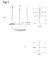
- Fig. 2 shows aberration diagrams in the infinity in-focus state in the wide-angle end state in the first example
- Fig. 3 aberration diagrams in the infinity in-focus state in the intermediate focal length state
- Fig. 4 (a) aberration diagrams in the infinity in-focus state in the telephoto end state
- Fig. 5 (a) aberration diagrams in the near object in-focus state in the wide-angle end state
- Fig. 5 (b) aberration diagrams in the near object in-focus state in the intermediate focal length state
- Fig. 2 shows aberration diagrams in the infinity in-focus state in the wide-angle end state in the first example
- Fig. 3 aberration diagrams in the infinity in-focus state in the intermediate focal length state
- Fig. 4 (a) aberration diagrams in the infinity in-focus state in the telephoto end state
- Fig. 5 (a)
- FIG. 2 (b) shows a meridional transverse aberration diagram with a movement compensation for rotational movement of 0.40° in the infinity photography state in the wide-angle end state in the first example
- Fig. 4 (b) a meridional transverse aberration diagram with a movement compensation for rotational movement of 0.30° in the infinity photography state in the telephoto end state in the first example.
- Fig. 6 is a drawing showing a configuration of a variable magnification optical system ZL2 according to the second example.
- the first lens unit G1 is composed of, in order from the object side, a cemented lens of a negative meniscus lens L11 with a convex surface on the object side and a positive meniscus lens L12 with a convex surface on the object side, a positive meniscus lens L13 with a convex surface on the object side, and a positive meniscus lens L14 with a convex surface on the object side.
- the second lens unit G2 is composed of, in order from the object side, a negative meniscus lens L21 with a convex surface on the object side, a cemented lens of a biconcave lens L22 and a positive meniscus lens L23 with a convex surface on the object side, and a cemented lens of a positive meniscus lens L24 with a concave surface on the object side and a negative meniscus lens L25 with a concave surface on the object side.
- the third lens unit G3 is composed of, in order from the object side, a cemented lens of a negative meniscus lens L31 with a convex surface on me object side and a biconvex lens L32, and a biconvex lens L33.
- the fourth lens unit G4 is composed of a negative meniscus lens L41 with a concave surface on the object side.
- the 5a partial lens unit G5a is composed of, in order from the object side, a cemented lens of a biconvex tens L51 and a biconcave lens L52
- the 5b partial lens unit G5b is composed of, in order from the object side, a cemented lens of a positive meniscus lens L53 with a concave surface on the object side and a biconcave lens L54
- the 5c partial lens unit G5c is composed of, in order from the object side, a cemented lens of a negative meniscus lens L55 with a convex surface on the object side and a biconvex lens L56, a biconvex lens L57, and a negative meniscus lens L58 with a concave surface on the object side.
- the aperture stop S is located between the 5a partial lens unit G5a and the 5b partial lens unit G5b and
- the vibration reduction factor is 1.00 and the focal length is 71.4 (mm); therefore, the movement amount of the 5b partial lens unit G5b for compensation for the rotational movement of 0.40° is 0.50 (mm).
- the vibration reduction factor is 1.00 and the focal length is 196.0 (mm); therefore, the movement amount of the 5b partial lens unit G5b for compensation for the rotational movement of 0.30° is 1.03 (mm).
- Table 4 below provides values of specifications of the second example.
- Table 5 below shows the variable space data and overall lengths at respective focal lengths in the wide-angle end state, intermediate focal length state, and telephoto end state of the variable magnification optical system ZL2 according to this second example.
- Table 6 below provides the value corresponding to the condition in this second example.
- Fig. 7 (a) shows aberration diagrams in the infinity in-focus state in the wide-angle end state in the second example
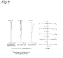
- Fig. 8 aberration diagrams in the infinity in-focus state in the intermediate focal length state
- Fig. 9 (a) aberration diagrams in the infinity in-focus state in the telephoto end state
- Fig. 10 (a) aberration diagrams in the near object in-focus state in the wide-angle end state
- Fig. 7 (a) shows aberration diagrams in the infinity in-focus state in the wide-angle end state in the second example
- Fig. 8 aberration diagrams in the infinity in-focus state in the intermediate focal length state
- Fig. 9 (a) aberration diagrams in the infinity in-focus state in the telephoto end state
- FIG. 7 (b) shows a meridional transverse aberration diagram with a movement compensation for rotational movement of 0.4C° in the infinity photography state in the wide-angle end state in the second example
- Fig. 9 (b) a meridional transverse aberration diagram with a movement compensation for rotational movement of 0.30° in the infinity photography state in the telephoto end state in the first example.
- Fig. 11 is a drawing showing a configuration of a variable magnification optical system ZL3 according to the third example.
- the first lens unit G1 is composed of, in order from the object side, a cemented lens of a negative meniscus lens L11 with a convex surface on the object side and a positive meniscus lens L12 with a convex surface on the object side, a positive meniscus lens L13 with a convex surface on the object side, and a positive meniscus lens L14 with a convex surface on the object side.
- the second lens unit G2 is composed of, in order from the object side, a negative meniscus lens L21 with a convex surface on the object side, a cemented lens of a biconcave lens L22 and a positive meniscus lens L23 with a convex surface on the object side, and a cemented lens of a positive meniscus lens L24 with a concave surface on the object side and a negative meniscus lens L25 with a concave surface on the object side.
- the third lens unit G3 is composed of, in order from the object side, a positive meniscus lens L31 with a concave surface on the object side, and a cemented lens of a negative meniscus lens L32 with a convex surface on the object side and a biconvex lens L33.
- the fourth lens unit G4 is composed of a negative meniscus lens L41 with a concave surface on the object side.
- the 5a partial lens unit G5a is composed of, in order from the object side, a biconvex lens L51 and a positive meniscus lens L52 with a convex surface on the object side
- the 5b partial lens unit G5b is composed of, in order from the object side, a cemented lens of a positive meniscus lens L53 with a concave surface on the object side and a biconcave lens L54, and a negative meniscus lens L55 with a convex surface on the object side
- the 5c partial lens unit G5c is composed of, in order from the object side, a biconvex lens L56, a biconvex lens L57, and a negative meniscus lens L58 with a concave surface on the object side.
- the aperture stop S is located nearest to the object in the fifth lens unit G5 and included in the 5a partial lens unit G5b.
- the vibration reduction factor is 1.30 and the focal length is 71.4 (mm); therefore, the movement amount of the 5b partial lens unit G5b for compensation for the rotational movement of 0.40° is 0.38 (mm).
- the vibration reduction factor is 1.30 and the focal length is 196.0 (mem); therefore, the movement amount of the 5b partial lens unit G5b for compensation for the rotational movement of 0.30° is 0.79 (mm).
- Table 7 below provides values of specifications of the third example.
- Table 8 below shows the variable space data and overall lengths at respective focal lengths in the wide-angle end state, intermediate focal length state, and telephoto end state of the variable magnification optical system ZL3 according to this third example.
- Table 9 provides the value corresponding to the condition in this third example.
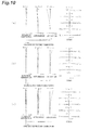
- Fig. 12 shows aberration diagrams in the infinity in-focus state in the wide-angle end state in the third examples
- Fig. 13 aberration diagrams in the infinity in-focus state in the intermediate focal length state
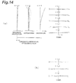
- Fig. 14 (a) aberration diagrams in the infinity in-foeus state in the telephoto end state
- Fig. 15 (a) aberration diagrams in the near object in-focus state in the wide-angle end state
- Fig. 12 shows aberration diagrams in the infinity in-focus state in the wide-angle end state in the third examples
- Fig. 13 aberration diagrams in the infinity in-focus state in the intermediate focal length state
- Fig. 14 (a) aberration diagrams in the infinity in-foeus state in the telephoto end state
- variable magnification optical system of the third example is well corrected for the various aberrations in each of the focal length states from the wide-angle end state to the telephoto end state and has excellent imaging performance.
- Fig. 18 is a drawing showing a configuration of a variable magnification optical system ZL4 according to the fourth example.
- This variable magnification optical system ZL4 of Fig. 18 has, in order from the object side, a first lens unit G1 having a positive refractive power, a second lens unit G2 having a negative refractive power, a third lens unit G3 having a positive refractive power, and a fourth lens unit G4 having a positive refractive power.
- the third lens unit G3 has, in order from the object side, a front partial lens unit G3a, and a rear partial lens unit G3b arranged with an air space to the front partial lens unit G3a.
- variable magnification optical system ZL4 during variable magnification, the first lens unit G1 and the fourth lens unit G4 are fixed, the second lens unit G2 and the third lens unit G3 move in the optical-axis direction, and an air space between the front partial lens unit G3a and the rear partial lens unit G3b varies.
- variable magnification optical system ZL4 during focusing, at least one of the front partial lens unit G3a and the rear partial lens unit G3b moves and the other is fixed.
- the fourth lens unit G4 moves so as to have a component in a substantially orthogonal direction to the optical axis.
- the first lens unit G1 is composed of, in order from the object side, a cemented lens of a negative meniscus lens L11 with a convex surface on the object side and a biconvex lens L12, a biconvex lens L13, and a positive meniscus lens L14 with a convex surface on the object side.
- the second lens unit G2 is composed of, in order from the object side, a negative meniscus lens L21 with a convex surface on the object side, a cemented lens of a biconcave lens L22 and a positive meniscus lens L23 with a convex surface on the object side, and a negative meniscus lens L24 with a concave surface on the object side.
- the front partial lens unit G3a of the third lens unit G3 is composed of, in order from the object side, a cemented lens of a positive meniscus lens L31 with a convex surface on the object side and a negative meniscus lens L32 with a convex surface on the object side.
- the rear partial lens unit G3b of the third lens unit G3 is composed of, in order from the object side, a positive meniscus lens L41 with a concave surface on the object side, and a cemented lens of a biconvex lens L42 and a biconcave lens L43.
- the first partial unit G4a is composed of a positive meniscus lens L51 with a convex surface on the object side
- the second partial unit G4b is composed of, in order from the object side, a cemented lens of a biconvex lens L52 and a biconcave lens L53, and a biconcave lens L54
- the third partial unit G4c is composed of in order from the object side, a biconvex lens L55, and a cemented lens of a biconvex lens L56 and a negative meniscus lens L57 with a concave surface on the object side.
- the closure stop S is located nearest to the object in the fourth lens unit G4 and included in the first partial unit G4a.
- the vibration reduction factor is 1.00 and the focal length is 71.4 (mm); therefore, the movement amount of the second partial unit G5b for compensation for the rotational movement of 0,40° is 0.50 (mm).
- the vibration reduction factor is 1.00 and the focal length is 135.0 (mm); therefore, the movement amount of the second partial unit G6b for compensation for the rotational movement of 0.30° is 0.71 (mm).
- the (vibration reduction factor is 1.00 and the focal length is 196.0 (mm); therefore, the movement amount of the second partial unit G5b for compensation for the rotational movement of 0.30° is 1.03 (mm).
- Table 13 below provides values of specifications of this fourth example.
- variable magnification-Table 14 shows the variable space data, Bf, and overall lengths at respective focal lengths in the wide-angle end state, intermediate focal length state, and telephoto end state of the variable magnification optical system ZL4 according to this fourth example.
- Fig. 19 shows aberration diagrams in the infinity in-focus state in the wide-angle end state in the fourth example
- Fig. 20 (a) aberration diagrams in the infinity in-focus state in the intermediate focal length state
- Fig. 21 (a) aberration diagrams in the infinity in-focus state in the telephoto end statue
- Fig. 22 (a) aberration diagrams in the near object in-focus state in the wide-angle end state
- Fig. 20 (a) aberration diagrams in the infinity in-focus state in the intermediate focal length state
- Fig. 21 (a) aberration diagrams in the infinity in-focus state in the telephoto end statue
- Fig. 22 (a) aberration diagrams in the near object in-focus state in the wide-angle end state
- Fig. 22
- FIG. 19 (b) shows a meridional transverse aberration diagram with a movement compensation for the rotational movement of 0.40° in the infinity in-focus state in the wide-angle end state in the fourth example
- Fig. 20(b) a meridional transverse aberration diagram with a movement compensation for the rotational movement of 0.30° in the infinity in-focus state in the intermediate focal length state in the fourth example
- Fig. 21 (b) a meridional transverse aberration diagram with a movement compensation for the rotational movement of 0.30° in the infinity in-focus state in the telephoto end state in the fourth example.
Landscapes
- Physics & Mathematics (AREA)
- General Physics & Mathematics (AREA)
- Optics & Photonics (AREA)
- Nonlinear Science (AREA)
- Lenses (AREA)
- Adjustment Of Camera Lenses (AREA)
Abstract
Description
- The present invention relates to a variable magnification optical system, an optical apparatus provided with the variable magnification optical system, and a method for variable magnification using the variable magnification optical system.
- There are hitherto-proposed variable magnification optical systems suitable for photographic cameras, electronic still cameras, video cameras, and so on (e.g., of. Patent Literature 1).
- Patent Literature 1: Japanese Patent Application Laid-open No.
2006-201524 - However, the conventional variable magnification optical systems had a problem that they tailed to deal with a compensation matter for camera shake.
- The present invention has been accomplished in view of this problem and it is an object of the present invention to provide a variable magnification optical system with optical performance capable of dealing with the compensation matter for camera shake, an optical apparatus provided with the variable magnification optical system, and a method for variable magnification using the variable magnification optical system.
- In order to solve the above problem, a variable magnification optical system according to the first aspect of the present invention is a variable magnification optical system comprising: a first lens unit with a positive refractive power arranged nearest to an object; a second lens unit arranged on the image plane side of the first lens unit; a Gn lens unit arranged nearest to the image plane; a Gn-1 lens unit arranged on the object side of the Gn lens unit; and at least one lens unit arranged between the second lens unit and the Gn-1 lens unit, wherein, in variable magnification, the first lens unit and the Gn lens unit are fixed, wherein, in focusing, at least one lens unit arranged between the second lens unit and the Gn-1 lens unit moves, and wherein at least a part of the Gn lens unit moves so as to have a component in a substantially orthogonal direction to the optical axis.
- This variable magnification optical system preferably satisfies a condition of the following expression:

where fGn-1 is the focal length of the Gn-1 lens unit and fw the focal length of the entire system in a wide-angle end state. - This variable magnification, optical system preferably comprises, in order from the object side, the first lens unit, the second lens unit, a third lens unit, a fourth lens unit, and a fifth lens unit,
- A variable magnification optical system according to the second aspect of the present invention is a variable magnification optical system comprising, in order from the object side: a first lens unit having a positive refractive power; a second lens unit having a negative refractive power; a third lens unit having a positive refractive power; a fourth lens unit having a negative refractive power; and a fifth lens unit having a positive refractive power, wherein, in variable magnification, the first lens unit is fixed, wherein, in focusing, the third lens unit moves, and wherein at least a part of the fifth lens unit moves so as to have a component in a substantially orthogonal direction to the optical axis.
- This variable magnification optical system is preferably configured so that, in variable magnification, the fifth lens unit is fixed.
- This variable magnification optical system preferably satisfies a condition of the following expression:

where fGn-1 is the focal length of the fourth lens unit and fw the focal length of the entire system in a wide-angle end state. - In this variable magnification optical system, preferably, the fourth lens unit consists of a lens component.
- In this variable magnification optical system, preferably, the fourth lens unit consists of a negative meniscus lens.
- A variable magnification optical system according to the third aspect of the present invention is a variable magnification optical system comprising, in order from the object side: a first lens unit having a positive refractive power; a second lens unit having a negative refractive power; a third lens unit having a positive refractive power; and a fourth lens unit having a positive refractive power, wherein the third lens unit comprises, in order from the object side, a front partial lens unit, and a rear partial lens unit arranged with an air space to the front partial lens unit, wherein, in variable magnification, the first lens unit and the fourth lens unit are fixed and the air space between the front partial lens unit and the rear partial lens unit varies, wherein, in focusing, at least one of the front partial lens unit and the rear partial lens unit moves, and wherein at least a part of the fourth lens unit moves so as to have a component in a substantially orthogonal direction to the optical axis.
- An optical apparatus according to the present invention comprises any one of the above-described variable magnification optical systems.
- A magnification varying method of a variable magnification optical system according to the present invention is a method for variable magnification using a variable magnification optical system comprising: a first lens unit with a positive refractive power arranged nearest to an object; a second lens unit arranged on the image plane side of the first lens unit; a Gn lens unit which is arranged nearest to the image plane and at least a part of which moves so as to have a component in a substantially orthogonal direction to the optical axis; a Gn-1 lens unit arranged on the object side of the Gn lens unit; and a focusing lens unit arranged between the second lens unit and the Gn-1 lens unit, the method comprising: fixing the first lens unit and the Gn lens unit; and moving at least one lens unit arranged between the first lens unit and the Gn lens unit.
- When the variable magnification optical system, the optical apparatus with the variable magnification optical system, and the method for variable magnification using the variable magnification optical system according to the present invention are configured as described above, they achieve the optical performance capable of dealing with the compensation matter for camera shake.
-
-
Fig. 1 is a cross-sectional view showing a configuration of a variable magnification optical system according to the first example. -
Fig. 2 is aberration diagrams in the infinity in-focus state in the first example, wherein (a) is aberration diagrams in the wide-angle end state and (b) a meridional transverse aberration diagram with a movement compensation for rotational movement of 0.40° in the infinity photography state in the wide-angle end state. -
Fig. 3 is aberration diagrams in an intermediate focal length state in the first example. -
Fig. 4 is aberration diagrams in the infinity in-focus state in the first example, wherein (a) is aberration diagrams in the telephoto end state and (b) a meridional transverse aberration diagram with a movement compensation for rotational movement of 0.30° in the infinity photography state in the telephoto end state. -
Fig. 5 is aberration diagrams in a near object in-focus state in the first example, wherein (a) is aberration diagrams in the near object in- focus state in the wide-angle end state, (b) aberration diagrams in the near object in-focus state in an intermediate focal length state, and (c) aberration diagrams in the near object in-focus state in the telephoto end state. -
Fig. 6 is a cross-sectional view showing a configuration of a variable magnification optical system according to the second example. -
Fig. 7 is aberration diagrams in the infinity in-focus state in the second example, wherein (a) is aberration diagrams in the wide-angle end state and (b) a meridional transverse aberration diagram with a movement compensation for rotational movement of 0.40° in the infinity photography state in the wide-angle end state. -
Fig. 8 is aberration diagrams in an intermediate focal length state in the second example. -
Fig. 9 is aberration diagrams in the infinity in-focus state in the second example, wherein (a) is aberration diagrams in the telephoto end state and (b) a meridional transverse aberration diagram with a movement compensation for rotational movement of 0.30° in the infinity photography state in the telephoto end state. -
Fig. 10 is aberration diagrams in a near object in-focus state in the second example, wherein (a) is aberration diagrams in the near object in-focus state in the wide-angle end state, (b) aberration diagrams in the near object in-focus state in an intermediate focal length state, and (c) aberration diagrams in the near object in-focus state in the telephoto end state. -
Fig. 11 is a cross-sectional view showing a configuration of a variable magnification optical system according to the third example. -
Fig. 12 is aberration diagrams in the infinity in-focus state in the third example, wherein (a) is aberration diagrams in the wide-angle end state and (b) a meridional transverse aberration diagram with a movement compensation for rotational movement of 0.40° in the infinity photography state in the wide-angle end state. -
Fig. 13 is aberration diagrams in an intermediate focal length state in the third example. -
Fig. 14 is aberration diagrams in the infinity in-focus state in the third example, wherein (a) is aberration diagrams in the telephoto end state and (b) a meridional transverse aberration diagram with a movement compensation for rotational movement of 0.30° in the infinity photography state in the telephoto end state. -
Fig. 15 is aberration diagrams in a near object in-focus state in the third example, wherein (a) is aberration diagrams in the near object in-focus state in the wide-angle end state, (b) aberration diagrams in the near object in-focus state in an intermediate focal length state, and (c) aberration diagrams in the near object in-focus state in the telephoto end state. -
Fig. 16 shows an electronic still camera loaded with a variable magnification optical system according to the present invention, wherein (a) is a front view and (b) a back view. -
Fig. 17 is a cross-sectional view along line A-A' ofFig. 16 (a) . -
Fig. 18 is a cross-sectional view showing a configuration of a variable magnification optical system according to the fourth example. -
Fig. 19 is aberration diagrams in the infinity in-focus state in the fourth example, wherein (a) is aberration diagrams in the wide-angle end state and (b) a meridional transverse aberration diagram with a movement compensation for rotational movement of 0.40° in the infinity photography state in the wide-angle end state. -
Fig. 20 is aberration diagrams in the infinity in-focus state in the fourth example, wherein (a) is aberration diagrams in an intermediate focal length state and (b) a meridional transverse aberration diagram with a movement compensation for rotational movement of 0.30° in the infinity photography state in the intermediate focal length state. -
Fig. 21 is aberration diagrams in the infinity in-fbcus state in the fourth example, wherein (a) is aberration diagrams in the telephoto end state and (b) a meridional transverse aberration diagram with a movement compensation for rotational movement of 0.30° in the infinity photography state in the telephoto end state. -
Fig. 22 is aberration diagrams in a near object in-focus state in the fourth example, wherein (a) is aberration diagrams in the near object in-focus state in the wide-angle end state, (b) aberration diagrams in the near object in-focus state in an intermediate focal length state, and (c) aberration diagrams in the near object in-focus state in the telephoto end state. - A preferred embodiment of the present invention will be described below with reference to the drawing. As shown in
Fig. 1 , a variable magnification optical system ZL according to the present embodiment is configured to have, in order from the object side, a first lens unit G1 having a positive retroactive power, a second lens unit G2 having a negative refractive power, a third lens unit G3 having a positive refractive power, a fourth lens unit G4 having a positive refractive power, and a fifth lens unit G5 having a positive refractive power. When the optical system is configured in this manner, it achieves downsizing of the entire tens cylinder. The variable magnification optical system ZL may be configured in the following configuration as shows inFig. 18 : it has, in order from the object side, a first lens unit G1having a positive refractive power, a second lens unit G2 having a negative refractive power, a third lens unit G3 having a positive refractive power, and a fourth lens unit G4 having a positive refractive power; an air space between a front partial lens unit and a rear partial lens unit of the third lens unit G3 varies in variable magnification. - This variable magnification optical system ZL is desirably configured so that the first lens unit G1 is fixed during change in lens position state from the wide-angle end state to the telephoto end state. This is advantageous in simplification of a zoom mechanism.
- This variable magnification optical system ZL is desirably configured so that the Gn lens unit Gn arranged nearest to the image plane is fixed during the change in lens position state from the wide-angle end state to the telephoto end state. This configuration enables simplification of the zoom mechanism of the variable magnification optical system ZL. When an aperture stop S is arranged in or near the Gn lens unit Gn and when the Gn lens unit Gn and the aperture stop S are fixed during the change in lens position state from the wide-angle end state to the telephoto end state, the F-number can be made constant. When the first lens unit G1 and the Gn lens unit Gn are fixed during the change in lens position state from the wide-angle end state to the telephoto end state, the overall length of the variable magnification optical system ZL can be kept constant.
- Focusing from a far object to a near object is preferably implemented by moving the third lens unit G3 (or at least one of the front partial lens unit and the rear partial lens unit in the third lens unit). The third lens unit G3 (or at least one of the front partial lens unit and the rear partial lens unit in the third lens unit) is suitable for execution of focusing because it has the number of lenses and the outside diameter smaller than those of the other lens units. This configuration also achieves good optical performance in near object photography, without change in the overall length during focusing.
- In the variable magnification optical system ZL as described above, compensation for camera shake is preferably implemented by moving at least a part of the Gn lens unit Gn so as to have a component in a substantially orthogonal direction to the optical axis. This configuration enables downsizing and weight reduction of a camera shake compensating mechanism. Such movement as to have a component in a substantially orthogonal direction to the optical axis includes movement in the orthogonal direction to the optical axis, movement in an oblique direction to the optical axis, and rotational movement around a point on the optical axis as a center of notation.
- In this variable magnification optical system ZL, preferably, the fourth lens unit G4 (or, where one of the front partial lens unit and the rear partial lens unit in the third lens unit is defined as a focusing lens unit, the other lens unit) consists of a lens component. This configuration relaxes decentering coma and field tilt which can occur with decentering due to manufacturing errors.
- In this case, the fourth lens G4 imit (or, where one of the front partial lens unit and the rear partial lens unit in the third lens unit is defined as a focusing lens unit, the other lens unit) preferably consists of a negative meniscus lens, This configuration enables effective correction for spherical aberration and chromatic aberration at the telephoto end.
- Now, let us explain a condition for configuring the variable magnification optical system ZL as described above. First, when the variable magnification optical system ZL has the lens units from the first lens unit G1 to the Gn lens unit Gn, it preferably satisfies Condition (1) below where fGn-1 is the focal length of the Gn-1 lens unit Gn-1 and fw the focal length of the entire system in a wide-angle end state. In the present embodiment, since the lens units are arranged in a five-unit configuration (n = 5), the Gn-1 lens unit Gn-1represents the fourth lens unit G4 and fGn-1 the focal length of the fourth lens unit G4.
-

- Condition (1) defines the focal length of the Gn-1 lens unit Gn-1 (the fourth lens unit G4 in the present embodiment) to the focal length of the entire system in a wide-angle end state of variable magnification optical system ZL. If the ratio is over the upper limit of this Condition (1), the refractive power of the fourth lens unit G4 will become too weak to suppress variation in spherical aberration during variation in magnification; therefore, it is unpreferable. On the other hand, if the ratio is below the lower limit of Condition (1), the refractive power of the fourth lens unit G4 will become too strong to correct for chromatic aberration. In addition, it is also unpreferable because it increases the amount of decentering coma occurring with decentering due to manufacture errors. When the upper limit of Condition (1) is set to 3.5 and the lower limit thereof to 1.5, the effect of the present invention can be made more definite.
-
Figs. 16 and17 show a configuration of an electronic still camera 1 (which will be referred to simply as a camera) as an optical apparatus provided with the aforementioned variable magnification optical system ZL. Thiscamera 1 is configured as follows: when an unillustrated power button is pushed, an unillustrated shutter of a taking lens (variable magnification optical system ZL) becomes opened; the variable magnification optical system ZL focuses light from an unillustrated subject to form an image thereof on an imaging device C (e.g., CCD, CMOS, or the like) arranged on the image plane I. The subject image formed on the imaging device C is displayed on a liquid crystal monitor 2 arranged on the back of thecamera 1. A photographer determines a composition of the subject image while watching theliquid crystal monitor 2; then the photographer depresses arelease button 3 to take the subject image by the imaging device C; the image is recorded and stored in an unillustrated memory. - this
camera 1 is provided with anauxiliary light emitter 4 to emit auxiliary light for a dark subject, a wide (W)-tele (T)button 5 for zooming of the variable magnification optical system ZL from the wide-angle end state (W) to the telephoto end state (T), afunction button 6 to be used, for example, to set various conditions of thecamera 1, and so on. Thiscamera 1 may be a so-called single lens reflex camera provided with a half mirror, a focusing glass, a pentagonal prism, an eyepiece optical system, and so on. The variable magnification optical system ZL may be configured so as to be set in an interchangeable lens which can be detachably mounted on a single lens reflex camera. - The contents described below can be optionally adopted as long as the optical performance is not degraded.
- First, the above description and examples provided below show the variable magnification optical systems ZL of the five-unit configuration, but the above configurational conditions and others can also be applied to the other unit configurations such as six-unit and seven-unit configurations. Specifically, exemplary configurations include a configuration wherein at least one lens with a positive refractive index is added nearest to the object, a configuration wherein at least one lens with a positive refractive index or with a negative refractive index is added nearest to the image, and a configuration wherein three or more lens units are arranged between the second lens unit G2 and the fifth lens unit G5.
- Furthermore, the above description concerned the case where the third lens unit G3 was used for focusing, but, without having to be limited to this third lens unit G3, the focusing lens unit for focusing from an infinity object to a near object may be one configured so as to move a single lens unit or a plurality of lens units, or a partial lens unit in the optical-axis direction. In this case, the focusing lens unit may also be applied to autofocus and is also suitable for driving with a motor (such as an ultrasonic motor) for autofocus. Particularly, it is preferable to configure the third lens unit G3 as a focusing lens unit as described above, but it is also possible to achieve focusing by the fourth lens unit G4.
- In this variable magnification optical system ZL, a lens surface may be made as an aspherical surface. In this case, the aspherical surface may be an aspherical surface made by grinding, a glass mold aspherical surface molded in an aspherical shape of glass, or a composite aspherical surface obtained by forming a resin in an aspherical shape on a surface of glass. Furthermore, a lens surface may be made as a diffractive surface, and a lens may be made as a gradient index lens (GRIN lens) or a plastic lens.
- The aperture stop S is preferably arranged near or in the fifth lens unit G5 as described above, but a lens frame may be used instead thereof so as to serve as an aperture stop, without provision of an extra member as the aperture stop S.
- Furthermore, each lens surface may be provided with an antireflection coating having high transmittance over a wide wavelength range, thereby reducing flare and ghost and achieving high optical performance with high contrast.
- The variable magnification optical system ZL of the present embodiment has the 35 mm equivalent focal length of about 60-80 mm in the wide-angle end state and about 180-400 mm in the telephoto end state, and the variable magnification ratio of about 2-5.
- In the variable magnification optical system ZL of the present embodiment, preferably, the first lens unit G1 has at least two positive lens components and one negative lens component. The first lens unit G1 is preferably configured so that the lens components are arranged in the order of negative, positive, and positive from the object side. All these positive lens components are preferably single lenses. The negative lens component is preferably a cemented lens. The first lens unit G1 is configured without any path bending element such as a rectangular prism. The first lens unit G1 is preferably composed of the lens components having at least one spherical surface or aspherical surface, or composed of the lens components and a plane-parallel plate which transmits rays.
- In the variable magnification optical system ZL of the present embodiment, the second lens unit G2 preferably has at least one positive lens component and two negative lens components. The second lens unit G2 is preferably configured so that the lens components are arranged in the order of negative, negative, and positive from the object side. The second and third lens components are preferably cemented to each other. Furthermore, a negative lens component may be added nearest to the image plane in the second lens unit G2.
- In the variable magnification optical system ZL of the present embodiment, the third lens unit G3 preferably has at least one positive lens component and one negative lens component. The third lens unit G3 may be composed of a cemented lens.
- The variable magnification optical system ZL of the present embodiment may be configured as the fifth lens unit G5 has positive, negative, and positive partial lens units (5a partial lens unit G5a, 5b partial lens unit G5b, and 5c partial lens unit G5c); the 5b partial lens unit G5b is moved in a substantially orthogonal direction to the optical axis, thereby achieving compensation for camera shake (vibration reduction). This configuration enables reduction in the diameter of the variable magnification optical system ZL. Preferably, the 5a partial lens unit G5a has at least one positive lens component, the 5b partial lens unit G5b has at least one cemented lens, and the 5c partial lens unit G5c has at least one negative lens component and one positive lens component.
- The constituent features of the embodiment were described above in order to describe the present invention in an easily understood manner but it is needless to mention that the present invention is by no means limited to them.
- Each of examples of the present invention will be described below on the basis of the accompanying drawings.
Fig. 1 shows a refractive power layout of this variable magnification optical system ZL and states of movement of the respective lens units during change in focal length state from the wide-angle end state (W) to the telephoto end state (T). As shown in thisFig. 1 , the variable magnification optical system ZL according to the present example is composed of, in order from the object side, a first lens unit G1 having a positive refractive power, a second lens unit G2 having a negative refractive power, a third lens unit G3 having a positive refractive power, a fourth lens unit G4 having a negative refractive power, and a fifth lens unit G5 having a positive refractive power. The fifth lens unit G5 is composed of, in order from the object side, a 5a partial lens unit G5a having a positive refractive power, a 5b partial lens unit G5b having a negative refractive power, and a 5c partial lens unit G5c having a positive refractive power. The variable magnification optical system ZL is configured so that in variation in magnification from the wide-angle end state to the telephoto end state, while the first lens unit Glad the fifth lens unit G5 are fixed, the third lens unit G3 is moved along the optical axis to implement focusing from a far object to a near object and the 5b partial lens unit G5b of the fifth lens unit G5 is moved in a substantially orthogonal direction to the optical axis to implement compensation for camera shake (vibration reduction). - The variable magnification optical system ZL shown in
Fig. 1 shows a configuration of a variable magnification optical system ZL1 according to the first example, and in this variable magnification optical system ZL1, the first lens unit G1 is composed of, in order from the object side, a cemented tens of a negative meniscus lens L11 with a convex surface on the object side and a positive meniscus lens L12 with a convex surface on the object side, a biconvex lens L13, and a positive meniscus lens L14 with a convex surface on the object side. The second lens unit G2 is composed of, in order from the object side, a negative meniscus lens L21 with a convex surface on the object side, a cemented lens of a biconcave lens L22 and a positive meniscus lens L23 with a convex surface on the object side, and a negative meniscus lens L24 with a concave surface on the object side. The third lens unit G3 is composed of, in order from the object side, a cemented lens of a negative meniscus lens L3 with a convex surface on the object side and a biconvex lens L32, and a biconvex lens L33. The fourth lens unit G4 is composed of a negative meniscus lens L41 with a concave surface on the object side. In the fifth lens unit G5, the 5a partial lens unit G5a is composed of, in order from the object side, a cemented lens of a negative meniscus lens L51 with a convex surface on the object side and a biconvex lens L52, the 5b partial lens unit G5b is composed of, in order from the object side, a cemented lens of a positive meniscus lens L53 with a concave surface on the object side and a biconcave lens L54, and the 5c partial lens unit G5c is composed of, in order from the object side, a cemented lens of a negative meniscus lens L55 with a convex surface on the object side and a biconvex lens L56, a positive meniscus lens L57 with a convex surface on the object side, and a negative meniscus lens L58 with a concave surface on the object side. The aperture stop S is located nearest to the object in the fifth lens unit G5 and included in the 5a partial lens unit G5a. - For compensating for rotational movement of angle θ by a lens wherein the focal length of the entire system in a wide-angle end state is f and wherein a vibration reduction factor (ratio of image movement amount on the image plane to movement amount of a moving lens unit in vibration compensation) is K, the moving lens unit for vibration compensation may be moved in the orthogonal direction to the optical axis by (f·tanθ)/K (this relation also applies to examples heremafter). In the wide-angle end state in the first example, the vibration reduction factor is 1.20 and the focal length is 71.4 (mm); therefore, the movement amount of the 5b partial lens unit G5b for compensation for rotational movement of 0.40° is 0.42 (mm), In the telephoto end state in the first example, the vibration reduction factor is 1.20 and the focal length is 196.0 (mm); therefore, the movement amount of the 5b partial lens unit G5b for compensation for rotational movement of 0.30° is 0.86 (mm).
- Table 1. below provides values of specifications of the first example. In this Table 1, f represents the focal length, FNO the F-number, and 2ω the angle of view. Furthermore, the surface number represents an order of each lens surface from the object side along the traveling direction of rays, the surface separation an axial distance from each optical surface to a next optical surface, the refractive index and Abbe number values for the d line (λ = 587.6 nm), and Bf an axial distance from the last surface to the image plane I (back focus). The unit of the focal length, radius of curvature, surface separation, and other lengths in all the specification values below is generally "mm," but does not have to be limited to it because equivalent optical performance can also be achieved by proportional enlargement or proportional reduction of the optical system. It should be noted that the radius of curvature of 0.0000 indicates a plane and the refractive index of air of 1.00000 is omitted. The notation of these signs and the description of specification table also apply similarly to the examples below.
-


- In this first example, an axial air space d1 between the first lens unit G1 and the second lens unit G2, an axial air space d2 between the second lens unit G2 and the third lens unit G3, an axial air space d3 between the third lens unit G3 and the fourth lens unit G4, and an axial air space d4 between the fourth lens unit G4 and the fifth lens unit G5 change in variable magnification. Table 2 below shows the variable space data and overall lengths at respective focal lengths in the wide-angle end state, an intermediate focal length state, and the Telephoto end state of the variable magnification optical system ZL1 according to this first example.
-
(Table 2) [Variable space data] Wild-angle
endIntermediate
focal lengthTelephoto
endd1 2.000 23.001 30.816 d2 29.816 15.626 2.943 d3 6.617 14.919 19.787 d4 17.113 2.000 2.000 overall length 253.180 253.180 253.180 - Table 3 below shows the value corresponding to the condition in this first example. In this Table 3, represents the focal length of the fourth lens unit G4 and fw the focal length of the entire system in a wide-angle end state of the variable magnification optical system ZL. This notation of signs also applies to the examples below.
-
(Table 3) (1) | f Gn-1 | / f w =2.626 -
Fig. 2 (a) shows aberration diagrams in the infinity in-focus state in the wide-angle end state in the first example,Fig. 3 aberration diagrams in the infinity in-focus state in the intermediate focal length state,Fig. 4 (a) aberration diagrams in the infinity in-focus state in the telephoto end state,Fig. 5 (a) aberration diagrams in the near object in-focus state in the wide-angle end state,Fig. 5 (b) aberration diagrams in the near object in-focus state in the intermediate focal length state, andFig. 5 (c) aberration diagrams in the near object in-focus state in the telephoto end state.Fig. 2 (b) shows a meridional transverse aberration diagram with a movement compensation for rotational movement of 0.40° in the infinity photography state in the wide-angle end state in the first example andFig. 4 (b) a meridional transverse aberration diagram with a movement compensation for rotational movement of 0.30° in the infinity photography state in the telephoto end state in the first example. - In each aberration diagram, FNO represents the F-number, Y ain image height, d the d line (λ = 587.6 nm), and g the g line (λ = 435.6 nm). In the aberration diagrams showing astigmatism, a solid line indicates a sagittal image surface and a dashed line a meridional image surface. The description of aberration diagrams also applies similarly to the examples below. As apparent from the aberration diagrams, it is seen that the variable magnification optical system of the first example is well corrected for the various aberrations in each of the focal length states from the wide-angle end state to the telephoto end state and has excellent imagine performance.
-
Fig. 6 is a drawing showing a configuration of a variable magnification optical system ZL2 according to the second example. In this variable magnification optical system ZL2 ofFig. 6 , the first lens unit G1 is composed of, in order from the object side, a cemented lens of a negative meniscus lens L11 with a convex surface on the object side and a positive meniscus lens L12 with a convex surface on the object side, a positive meniscus lens L13 with a convex surface on the object side, and a positive meniscus lens L14 with a convex surface on the object side. The second lens unit G2 is composed of, in order from the object side, a negative meniscus lens L21 with a convex surface on the object side, a cemented lens of a biconcave lens L22 and a positive meniscus lens L23 with a convex surface on the object side, and a cemented lens of a positive meniscus lens L24 with a concave surface on the object side and a negative meniscus lens L25 with a concave surface on the object side. The third lens unit G3 is composed of, in order from the object side, a cemented lens of a negative meniscus lens L31 with a convex surface on me object side and a biconvex lens L32, and a biconvex lens L33. The fourth lens unit G4 is composed of a negative meniscus lens L41 with a concave surface on the object side. In the fifth lens unit G5, the 5a partial lens unit G5a is composed of, in order from the object side, a cemented lens of a biconvex tens L51 and a biconcave lens L52, the 5b partial lens unit G5b is composed of, in order from the object side, a cemented lens of a positive meniscus lens L53 with a concave surface on the object side and a biconcave lens L54, and the 5c partial lens unit G5c is composed of, in order from the object side, a cemented lens of a negative meniscus lens L55 with a convex surface on the object side and a biconvex lens L56, a biconvex lens L57, and a negative meniscus lens L58 with a concave surface on the object side. The aperture stop S is located between the 5a partial lens unit G5a and the 5b partial lens unit G5b and nearest to the image in the 5a partial lens unit G5a. - In the wide-angle end state in this second example, the vibration reduction factor is 1.00 and the focal length is 71.4 (mm); therefore, the movement amount of the 5b partial lens unit G5b for compensation for the rotational movement of 0.40° is 0.50 (mm). In the telephoto end state in the second example, the vibration reduction factor is 1.00 and the focal length is 196.0 (mm); therefore, the movement amount of the 5b partial lens unit G5b for compensation for the rotational movement of 0.30° is 1.03 (mm).
- Table 4 below provides values of specifications of the second example.
-


- Table 5 below shows the variable space data and overall lengths at respective focal lengths in the wide-angle end state, intermediate focal length state, and telephoto end state of the variable magnification optical system ZL2 according to this second example.
-
(Table 5) [Variable space data] Wild-angle
endIntermediate
focal lengthTelephoto
endd1 2.000 25.437 33.995 d2 24.330 12.566 2.000 d3 4.668 10.865 14.953 d4 21.950 4.080 2.000 overall length 259.180 259.180 259.180 - Table 6 below provides the value corresponding to the condition in this second example.
-
(Table 6) (1) | f Gn-1 | / f w = 2.489 -
Fig. 7 (a) shows aberration diagrams in the infinity in-focus state in the wide-angle end state in the second example,Fig. 8 aberration diagrams in the infinity in-focus state in the intermediate focal length state,Fig. 9 (a) aberration diagrams in the infinity in-focus state in the telephoto end state,Fig. 10 (a) aberration diagrams in the near object in-focus state in the wide-angle end state,Fig. 10 (b) aberration diagrams in the near object in-focus state in the intermediate focal length state, andFig. 10 (c) aberration diagrams in the near object in-fbcus state in the telephoto end state.Fig. 7 (b) shows a meridional transverse aberration diagram with a movement compensation for rotational movement of 0.4C° in the infinity photography state in the wide-angle end state in the second example andFig. 9 (b) a meridional transverse aberration diagram with a movement compensation for rotational movement of 0.30° in the infinity photography state in the telephoto end state in the first example. As apparent from the aberration diagrams, it is seen that the variable magnification optical system of the second example is well corrected for the various aberrations in each of the focal length states from the wide-angle end state to the telephoto end state and has excellent imaging performance. -
Fig. 11 is a drawing showing a configuration of a variable magnification optical system ZL3 according to the third example. In this variable magnification optical system ZL23 ofFig. 11 , the first lens unit G1 is composed of, in order from the object side, a cemented lens of a negative meniscus lens L11 with a convex surface on the object side and a positive meniscus lens L12 with a convex surface on the object side, a positive meniscus lens L13 with a convex surface on the object side, and a positive meniscus lens L14 with a convex surface on the object side. The second lens unit G2 is composed of, in order from the object side, a negative meniscus lens L21 with a convex surface on the object side, a cemented lens of a biconcave lens L22 and a positive meniscus lens L23 with a convex surface on the object side, and a cemented lens of a positive meniscus lens L24 with a concave surface on the object side and a negative meniscus lens L25 with a concave surface on the object side. The third lens unit G3 is composed of, in order from the object side, a positive meniscus lens L31 with a concave surface on the object side, and a cemented lens of a negative meniscus lens L32 with a convex surface on the object side and a biconvex lens L33. The fourth lens unit G4 is composed of a negative meniscus lens L41 with a concave surface on the object side. In the fifth lens unit G5, the 5a partial lens unit G5a is composed of, in order from the object side, a biconvex lens L51 and a positive meniscus lens L52 with a convex surface on the object side, the 5b partial lens unit G5b is composed of, in order from the object side, a cemented lens of a positive meniscus lens L53 with a concave surface on the object side and a biconcave lens L54, and a negative meniscus lens L55 with a convex surface on the object side, and the 5c partial lens unit G5c is composed of, in order from the object side, a biconvex lens L56, a biconvex lens L57, and a negative meniscus lens L58 with a concave surface on the object side. The aperture stop S is located nearest to the object in the fifth lens unit G5 and included in the 5a partial lens unit G5b. - In the wide-angle end state in this third example, the vibration reduction factor is 1.30 and the focal length is 71.4 (mm); therefore, the movement amount of the 5b partial lens unit G5b for compensation for the rotational movement of 0.40° is 0.38 (mm). In the telephoto end state in the third example, the vibration reduction factor is 1.30 and the focal length is 196.0 (mem); therefore, the movement amount of the 5b partial lens unit G5b for compensation for the rotational movement of 0.30° is 0.79 (mm).
- Table 7 below provides values of specifications of the third example.
-


- Table 8 below shows the variable space data and overall lengths at respective focal lengths in the wide-angle end state, intermediate focal length state, and telephoto end state of the variable magnification optical system ZL3 according to this third example.
-
(Table 8) [Variable space data] Wild-angle
endIntermediate
focal lengthTelephoto
endd1 2.089 21.088 27.934 d2 24.923 12.762 2.000 d3 5.167 11.520 15.477 d4 16.232 3.041 3.000 overall length 247.180 247.180 247.180 - Table 9 below provides the value corresponding to the condition in this third example.
-
(Table 9) (1) | f Gn-1 | / f w=2.521 -
Fig. 12 (a) shows aberration diagrams in the infinity in-focus state in the wide-angle end state in the third examples,Fig. 13 aberration diagrams in the infinity in-focus state in the intermediate focal length state,Fig. 14 (a) aberration diagrams in the infinity in-foeus state in the telephoto end state,Fig. 15 (a) aberration diagrams in the near object in-focus state in the wide-angle end state,Fig. 15 (b) aberration diagrams in the near object in-focus state in the intermediate focal length state, andFig. 15 (c) aberration diagrams in the near object in-focus state in the telephoto end state.Fig. 12 (b) shows a meridional transverse aberration diagram with a movement compensation for rotational movement of 0,40° in the infinity photography state in the wide-angle end state in the third example andFig. 14 (b) a meridional transverse aberration diagram with a movement compensation for rotational movement of 0.30° in the infinity photography state in the telephoto end state in the third example. As apparent from the aberration diagrams, it is seen that the variable magnification optical system of the third example is well corrected for the various aberrations in each of the focal length states from the wide-angle end state to the telephoto end state and has excellent imaging performance. -
Fig. 18 is a drawing showing a configuration of a variable magnification optical system ZL4 according to the fourth example. This variable magnification optical system ZL4 ofFig. 18 has, in order from the object side, a first lens unit G1 having a positive refractive power, a second lens unit G2 having a negative refractive power, a third lens unit G3 having a positive refractive power, and a fourth lens unit G4 having a positive refractive power. The third lens unit G3 has, in order from the object side, a front partial lens unit G3a, and a rear partial lens unit G3b arranged with an air space to the front partial lens unit G3a. In the variable magnification optical system ZL4, during variable magnification, the first lens unit G1 and the fourth lens unit G4 are fixed, the second lens unit G2 and the third lens unit G3 move in the optical-axis direction, and an air space between the front partial lens unit G3a and the rear partial lens unit G3b varies. In the variable magnification optical system ZL4, during focusing, at least one of the front partial lens unit G3a and the rear partial lens unit G3b moves and the other is fixed. Furthermore, at least a part of the fourth lens unit G4 (negative partial lens unit G4b in the case where the fourth lens unit G4 has positive, negative, and positive partial lens units G4a, G4b, and G4c in order from the object side as in the present example) moves so as to have a component in a substantially orthogonal direction to the optical axis. - The first lens unit G1 is composed of, in order from the object side, a cemented lens of a negative meniscus lens L11 with a convex surface on the object side and a biconvex lens L12, a biconvex lens L13, and a positive meniscus lens L14 with a convex surface on the object side. The second lens unit G2 is composed of, in order from the object side, a negative meniscus lens L21 with a convex surface on the object side, a cemented lens of a biconcave lens L22 and a positive meniscus lens L23 with a convex surface on the object side, and a negative meniscus lens L24 with a concave surface on the object side. The front partial lens unit G3a of the third lens unit G3 is composed of, in order from the object side, a cemented lens of a positive meniscus lens L31 with a convex surface on the object side and a negative meniscus lens L32 with a convex surface on the object side. The rear partial lens unit G3b of the third lens unit G3 is composed of, in order from the object side, a positive meniscus lens L41 with a concave surface on the object side, and a cemented lens of a biconvex lens L42 and a biconcave lens L43. In the fourth lens unit G4, the first partial unit G4a is composed of a positive meniscus lens L51 with a convex surface on the object side, the second partial unit G4b is composed of, in order from the object side, a cemented lens of a biconvex lens L52 and a biconcave lens L53, and a biconcave lens L54, and the third partial unit G4c is composed of in order from the object side, a biconvex lens L55, and a cemented lens of a biconvex lens L56 and a negative meniscus lens L57 with a concave surface on the object side. The closure stop S is located nearest to the object in the fourth lens unit G4 and included in the first partial unit G4a.
- In the wide-angle end state in this fourth example, the vibration reduction factor is 1.00 and the focal length is 71.4 (mm); therefore, the movement amount of the second partial unit G5b for compensation for the rotational movement of 0,40° is 0.50 (mm). In the intermediate focal length state in the fourth example, the vibration reduction factor is 1.00 and the focal length is 135.0 (mm); therefore, the movement amount of the second partial unit G6b for compensation for the rotational movement of 0.30° is 0.71 (mm). In the telephoto end state in the fourth example, the (vibration reduction factor is 1.00 and the focal length is 196.0 (mm); therefore, the movement amount of the second partial unit G5b for compensation for the rotational movement of 0.30° is 1.03 (mm).
- Table 13 below provides values of specifications of this fourth example.
-


- In this fourth example, an axial air space D1 between the first lens unit G1 and the second lens unit G2, an axial air space d2 between the second lens unit G2 and the third lens unit G3, an axial air space d3 between the front partial lens unit G3a and the rear partial lens unit G3b of the third lens unit G3, and an axial air space d4 between the third lens unit G3 and the fourth lens unit G4 change in variable magnification-Table 14 below shows the variable space data, Bf, and overall lengths at respective focal lengths in the wide-angle end state, intermediate focal length state, and telephoto end state of the variable magnification optical system ZL4 according to this fourth example.
-
(Table 14) [Variable space data] Wild-angle
endIntermediate
focal lengthTelephoto
endd1 2.683 24.724 32.437 d2 24.804 16.117 2.000 d3 9.527 4.934 5.838 d4 17.138 8.376 13.875 Bf 72.476 72.476 72.476 overall length 259.180 259.180 259.180 -
Fig. 19 (a) shows aberration diagrams in the infinity in-focus state in the wide-angle end state in the fourth example,Fig. 20 (a) aberration diagrams in the infinity in-focus state in the intermediate focal length state,Fig. 21 (a) aberration diagrams in the infinity in-focus state in the telephoto end statue,Fig. 22 (a) aberration diagrams in the near object in-focus state in the wide-angle end state,Fig. 22 (b) aberration diagrams in the near object in-focus state in the intermediate focal length state, andFig. 22 (c) aberration diagrams in the near object in-focus state in the telephoto end state.Fig. 19 (b) shows a meridional transverse aberration diagram with a movement compensation for the rotational movement of 0.40° in the infinity in-focus state in the wide-angle end state in the fourth example,Fig. 20(b) a meridional transverse aberration diagram with a movement compensation for the rotational movement of 0.30° in the infinity in-focus state in the intermediate focal length state in the fourth example, andFig. 21 (b) a meridional transverse aberration diagram with a movement compensation for the rotational movement of 0.30° in the infinity in-focus state in the telephoto end state in the fourth example. As apparent from the aberration diagrams, it is seen that the variable magnification optical system of the fourth example is well corrected for the various aberrations in each of the focal length states from the wide-angle end state to the telephoto end state and has excellent imaging performance. - ZL (ZL1-ZL4) variable magnification optical system
- G1 first lens unit
- G2 second lens unit
- G3 third lens unit
- G4 fourth lens unit
- G5 fifth lens unit
- G5a 5a partial lens unit
- G5b 5b partial lens unit
- G5c 5c partial lens unit
- S aperture stop
- 1 electronic still camera (optical apparatus)
Claims (11)
- A variable magnification optical system comprising:a first lens unit arranged nearest to an object and having a positive refractive power;a second lens unit arranged on the image plane side of the first lens unit;a Gn lens unit arranged nearest to the image plane;a Gn-1 lens unit arranged on the object side of the Gn lens unit; andat least one lens unit arranged between the second lens unit and the Gn-1 lens unit,wherein, in variable magnification, the first lens unit and the Gn lens unit are fixed,wherein, in focusing, at least one lens unit arranged between the second lens unit and the Gn-1 lens unit moves, andwherein at least a part of the Gn lens unit moves so as to have a component in a substantially orthogonal direction to the optical axis.
- The variable magnification optical system according to claim 1, satisfying a condition of the following expression:

where fGn-1 is the focal length of the Gn-1 lens unit and fw the focal length of the entire system in a wide-angle end state. - The variable magnification optical system according to claim 1 or 2, comprising, in order from the object side, the first lens unit, the second lens unit, a third lens unit, a fourth lens unit, and a fifth lens unit.
- A variable magnification optical system comprising, in order from the object side:a first lens unit having a positive refractive power;a second lens unit having a negative refractive power;a third lens unit having a positive refractive power;a fourth lens unit having a negative refractive power; anda fifth lens unit having a positive refractive power,wherein, in variable magnification, the first lens unit is fixed,wherein, in focusing, the third lens unit moves, andwherein at least a part of the fifth lens unit moves so as to have a component in a substantially orthogonal direction to the optical axis.
- The variable magnification optical system according to claim 4, wherein, in variable magnification, the fifth lens unit is fixed.
- The variable magnification optical system according to claim 4 or 5, satisfying a condition of the following expression:

where fGn-1 is the focal length of the fourth lens unit and fw the focal length of the entire system in a wide-angle end state. - The variable magnification optical system according to any one of claims 3 to 6, wherein the fourth lens unit consists of a lens component.
- The variable magnification optical system according to any one of claims 3 to 7, wherein the fourth lens unit consists of a negative meniscus lens.
- A variable magnification optical system comprising, in order from the object side:a first lens unit having a positive refractive power;a second lens unit having a negative refractive power;a third lens unit having a positive refractive power; anda fourth lens unit having a positive refractive power,wherein the third lens unit comprises, in order from the object side, a front partial lens unit, and a rear partial lens unit arranged with an air space to the front partial lens unit,wherein, in variable magnification, the first lens unit and the fourth lens unit are fixed and the air space between the front partial lens unit and the rear partial lens unit varies,wherein, in focusing, at least one of the front partial lens unit and the rear partial lens unit moves, andwherein at least a part of the fourth lens unit moves so as to have a component in a substantially orthogonal direction to the optical axis.
- An optical apparatus comprising the variable magnification optical system as set forth in any one of claims 1 to 9.
- A method for variable magnification using a variable magnification optical system comprising: a first lens unit with a positive refractive power arranged nearest to an object; a second lens unit arranged on the image plane side of the first lens unit; a Gn lens unit which is arranged nearest to the image plane and at least a part of which moves so as to have a component in a substantially orthogonal direction to the optical axis; a Gn-1 lens unit arranged on the object side of the Gn lens unit; and a focusing lens unit arranged between the second lens unit and the Gn-1 lens unit,
the method comprising:fixing the first lens unit and the Gn lens unit; andmoving at least one lens unit arranged between the first lens unit and the Gn lens unit.
Applications Claiming Priority (2)
| Application Number | Priority Date | Filing Date | Title |
|---|---|---|---|
| JP2008183613 | 2008-07-15 | ||
| PCT/JP2009/062532 WO2010007939A1 (en) | 2008-07-15 | 2009-07-09 | Variable magnification optical system, optical apparatus provided with same and method for variable magnification using variable magnification optical system |
Publications (2)
| Publication Number | Publication Date |
|---|---|
| EP2309300A1 true EP2309300A1 (en) | 2011-04-13 |
| EP2309300A4 EP2309300A4 (en) | 2013-12-04 |
Family
ID=41550342
Family Applications (1)
| Application Number | Title | Priority Date | Filing Date |
|---|---|---|---|
| EP09797864.7A Withdrawn EP2309300A4 (en) | 2008-07-15 | 2009-07-09 | Variable magnification optical system, optical apparatus provided with same and method for variable magnification using variable magnification optical system |
Country Status (5)
| Country | Link |
|---|---|
| US (1) | US8730584B2 (en) |
| EP (1) | EP2309300A4 (en) |
| JP (1) | JP5549134B2 (en) |
| CN (1) | CN102067006B (en) |
| WO (1) | WO2010007939A1 (en) |
Cited By (2)
| Publication number | Priority date | Publication date | Assignee | Title |
|---|---|---|---|---|
| EP2741117A1 (en) * | 2012-12-04 | 2014-06-11 | Samsung Electronics Co., Ltd | Zoom lens and electronic device including the same |
| EP2778735A3 (en) * | 2013-03-12 | 2014-10-29 | Samsung Electronics Co., Ltd. | Telephoto zoom lens system and electronic apparatus including the same |
Families Citing this family (28)
| Publication number | Priority date | Publication date | Assignee | Title |
|---|---|---|---|---|
| US8416506B2 (en) * | 2009-02-20 | 2013-04-09 | Nikon Corporation | Zoom lens, optical apparatus equipped therewith and method for manufacturing the zoom lens |
| US9146386B2 (en) * | 2009-11-25 | 2015-09-29 | Nikon Corporation | Optical element, zoom lens, optical apparatus, method for manufacturing optical element and method for manufacturing zoom lens |
| JP5484197B2 (en) * | 2010-05-26 | 2014-05-07 | キヤノン株式会社 | Zoom lens and imaging apparatus having the same |
| JP5530872B2 (en) | 2010-09-10 | 2014-06-25 | 株式会社タムロン | Zoom lens |
| JP5467976B2 (en) | 2010-09-10 | 2014-04-09 | 株式会社タムロン | Zoom lens |
| JP5521996B2 (en) | 2010-11-19 | 2014-06-18 | 信越化学工業株式会社 | Polymer compound containing sulfonium salt, resist material and pattern forming method, sulfonium salt monomer and method for producing the same |
| JP5648907B2 (en) | 2010-11-26 | 2015-01-07 | 株式会社ニコン | Magnification optical system and optical instrument |
| EP2469319B1 (en) * | 2010-12-21 | 2021-06-09 | Samsung Electronics Co., Ltd. | Vibration proof zoom lens and photographing apparatus having the same |
| JPWO2013125603A1 (en) * | 2012-02-20 | 2015-07-30 | コニカミノルタ株式会社 | Zoom lens, imaging device, and portable terminal |
| JP5854876B2 (en) * | 2012-02-21 | 2016-02-09 | 株式会社タムロン | Zoom lens |
| JP5849767B2 (en) * | 2012-02-27 | 2016-02-03 | 株式会社ニコン | Variable magnification optical system and optical apparatus having the variable magnification optical system |
| JP5907616B2 (en) * | 2012-03-21 | 2016-04-26 | キヤノン株式会社 | Zoom lens and imaging apparatus having the same |
| JP5968096B2 (en) | 2012-06-14 | 2016-08-10 | キヤノン株式会社 | Zoom lens and optical apparatus having the same |
| EP2741116B1 (en) * | 2012-12-07 | 2015-06-24 | Samsung Electronics Co., Ltd | Zoom lens of the telephoto type having four lens groups with rear-focusing |
| JP6300070B2 (en) * | 2013-02-22 | 2018-03-28 | パナソニックIpマネジメント株式会社 | Zoom lens system, interchangeable lens device and camera system |
| JP6238123B2 (en) * | 2013-11-05 | 2017-11-29 | 株式会社リコー | Zoom lens and camera |
| JP6128607B2 (en) * | 2014-02-26 | 2017-05-17 | 富士フイルム株式会社 | Zoom lens and imaging device |
| CN110058391B (en) * | 2014-04-21 | 2021-11-23 | 株式会社尼康 | Variable magnification optical system and optical apparatus |
| EP3176624A4 (en) * | 2014-07-30 | 2018-03-28 | Nikon Corporation | Variable-power optical system, optical device, and method for manufacturing variable-power optical system |
| CN104199178B (en) * | 2014-08-06 | 2017-03-29 | 青岛歌尔声学科技有限公司 | a zoom lens |
| JP6406935B2 (en) * | 2014-09-02 | 2018-10-17 | キヤノン株式会社 | Zoom lens and imaging apparatus having the same |
| JP6439365B2 (en) * | 2014-10-09 | 2018-12-19 | リコーイメージング株式会社 | Zoom lens system |
| JP6558954B2 (en) * | 2015-05-28 | 2019-08-14 | キヤノン株式会社 | Zoom lens and optical apparatus having the same |
| JP2016224210A (en) | 2015-05-29 | 2016-12-28 | オリンパス株式会社 | Zoom lens and image capturing device having the same |
| JP6806157B2 (en) * | 2016-10-07 | 2021-01-06 | 株式会社ニコン | Variable magnification optics and optical equipment |
| JP6670262B2 (en) * | 2017-02-24 | 2020-03-18 | 富士フイルム株式会社 | Zoom lens and imaging device |
| TWI877167B (en) * | 2020-06-02 | 2025-03-21 | 佳能企業股份有限公司 | Optical lens and electronic apparatus |
| CN115166956B (en) * | 2022-07-05 | 2023-08-01 | 福建优恩立光电科技有限公司 | A zoom industrial lens for machine vision imaging |
Family Cites Families (33)
| Publication number | Priority date | Publication date | Assignee | Title |
|---|---|---|---|---|
| JPS5952215A (en) | 1982-09-20 | 1984-03-26 | Minolta Camera Co Ltd | Zoom lens system for automatic focusing |
| JPH036510A (en) | 1989-06-02 | 1991-01-14 | Minolta Camera Co Ltd | Five-element zoom lens |
| JPH05215967A (en) | 1992-02-04 | 1993-08-27 | Konica Corp | Wide-angle high-magnification zoom lens having a fixed group of positive refracting power |
| JP2988164B2 (en) | 1992-11-06 | 1999-12-06 | キヤノン株式会社 | Rear focus zoom lens |
| JPH08278445A (en) | 1995-04-04 | 1996-10-22 | Nikon Corp | Zoom lens with anti-vibration function |
| JPH09325274A (en) | 1996-06-03 | 1997-12-16 | Nikon Corp | Zoom lens |
| JP3754805B2 (en) * | 1996-09-19 | 2006-03-15 | キヤノン株式会社 | Zoom lens and optical apparatus using the same |
| JPH11142738A (en) * | 1997-11-14 | 1999-05-28 | Nikon Corp | Variable focal length lens system |
| JP3564014B2 (en) | 1999-09-28 | 2004-09-08 | キヤノン株式会社 | Zoom lens having anti-vibration function and television camera having the same |
| JP2002098895A (en) * | 2000-09-25 | 2002-04-05 | Olympus Optical Co Ltd | Zoom lens with image blur correction function |
| JP2002162563A (en) | 2000-11-24 | 2002-06-07 | Matsushita Kotobuki Electronics Industries Ltd | Zoom lens |
| JP4708553B2 (en) * | 2000-11-30 | 2011-06-22 | キヤノン株式会社 | Zoom lens and shooting system |
| JP4813670B2 (en) | 2001-01-30 | 2011-11-09 | パナソニック株式会社 | Zoom lens and video camera using the same |
| JP4388784B2 (en) * | 2003-10-14 | 2009-12-24 | フジノン株式会社 | Zoom lens with anti-vibration function |
| JP4496460B2 (en) * | 2004-01-05 | 2010-07-07 | ソニー株式会社 | Zoom lens and imaging device |
| JP2005345714A (en) | 2004-06-02 | 2005-12-15 | Konica Minolta Photo Imaging Inc | Imaging apparatus |
| JP2006071993A (en) * | 2004-09-02 | 2006-03-16 | Sony Corp | Zoom lens and imaging device |
| JP2006209100A (en) | 2004-12-28 | 2006-08-10 | Konica Minolta Opto Inc | Zoom lens and imaging apparatus |
| EP1677134B1 (en) | 2004-12-28 | 2015-07-01 | Konica Minolta Opto, Inc. | Zoom lens and image pickup apparatus |
| JP4746329B2 (en) | 2005-01-21 | 2011-08-10 | 株式会社シグマ | Large aperture telephoto zoom lens |
| JP4776936B2 (en) * | 2005-02-03 | 2011-09-21 | キヤノン株式会社 | Zoom lens and imaging apparatus having the same |
| JP4655205B2 (en) * | 2005-05-26 | 2011-03-23 | ソニー株式会社 | Zoom lens and imaging device |
| JP4766933B2 (en) | 2005-06-21 | 2011-09-07 | オリンパスイメージング株式会社 | Optical path folding zoom lens and image pickup apparatus having the same |
| US7372635B2 (en) | 2005-06-10 | 2008-05-13 | Olympus Imaging Corp. | Optical path bending type zoom lens system and image taking apparatus including the same |
| JP4182088B2 (en) | 2005-07-27 | 2008-11-19 | キヤノン株式会社 | Zoom lens and optical apparatus having the same |
| JP5289693B2 (en) | 2005-09-13 | 2013-09-11 | オリンパス株式会社 | Imaging optical system and electronic imaging apparatus having the same |
| JP2007108702A (en) | 2005-09-13 | 2007-04-26 | Olympus Imaging Corp | Imaging optical system and electronic imaging apparatus having the same |
| JP2007279351A (en) * | 2006-04-06 | 2007-10-25 | Fujinon Corp | Variable power optical system |
| JP4264842B2 (en) * | 2006-12-06 | 2009-05-20 | ソニー株式会社 | Zoom lens and imaging device |
| JP5040408B2 (en) * | 2007-04-11 | 2012-10-03 | ソニー株式会社 | Zoom lens and imaging device |
| JP5298661B2 (en) * | 2007-11-12 | 2013-09-25 | 株式会社リコー | Zoom lens and imaging device |
| JP2009192771A (en) * | 2008-02-14 | 2009-08-27 | Sony Corp | Zoom lens, image pickup apparatus, and zoom lens control method |
| US8416506B2 (en) | 2009-02-20 | 2013-04-09 | Nikon Corporation | Zoom lens, optical apparatus equipped therewith and method for manufacturing the zoom lens |
-
2009
- 2009-07-09 JP JP2009162469A patent/JP5549134B2/en active Active
- 2009-07-09 WO PCT/JP2009/062532 patent/WO2010007939A1/en not_active Ceased
- 2009-07-09 EP EP09797864.7A patent/EP2309300A4/en not_active Withdrawn
- 2009-07-09 CN CN2009801239411A patent/CN102067006B/en active Active
- 2009-07-09 US US13/054,060 patent/US8730584B2/en active Active
Cited By (4)
| Publication number | Priority date | Publication date | Assignee | Title |
|---|---|---|---|---|
| EP2741117A1 (en) * | 2012-12-04 | 2014-06-11 | Samsung Electronics Co., Ltd | Zoom lens and electronic device including the same |
| US9250425B2 (en) | 2012-12-04 | 2016-02-02 | Samsung Electronics Co., Ltd. | Zoom lens and electronic device including the same |
| EP2778735A3 (en) * | 2013-03-12 | 2014-10-29 | Samsung Electronics Co., Ltd. | Telephoto zoom lens system and electronic apparatus including the same |
| US9411138B2 (en) | 2013-03-12 | 2016-08-09 | Samsung Electronics Co., Ltd. | Telephoto zoom lens system and electronic apparatus including the same |
Also Published As
| Publication number | Publication date |
|---|---|
| EP2309300A4 (en) | 2013-12-04 |
| WO2010007939A1 (en) | 2010-01-21 |
| CN102067006B (en) | 2013-11-27 |
| US20110122506A1 (en) | 2011-05-26 |
| JP2010044372A (en) | 2010-02-25 |
| US8730584B2 (en) | 2014-05-20 |
| JP5549134B2 (en) | 2014-07-16 |
| CN102067006A (en) | 2011-05-18 |
Similar Documents
| Publication | Publication Date | Title |
|---|---|---|
| US8730584B2 (en) | Variable magnification optical system, optical apparatus provided with same and method for variable magnification using variable magnification optical system | |
| EP2107407B1 (en) | Telephoto vibration-proof zoom lens having five lens groups | |
| US8416506B2 (en) | Zoom lens, optical apparatus equipped therewith and method for manufacturing the zoom lens | |
| JP5288238B2 (en) | Magnifying optical system, optical apparatus equipped with the magnifying optical system, and magnifying method of the magnifying optical system | |
| EP2330452B1 (en) | Zoom lens, optical apparatus with the zoom lens, and method of manufacturing zoom lens | |
| JP5565649B2 (en) | Variable magnification optical system and optical apparatus equipped with the variable magnification optical system | |
| JP5836654B2 (en) | Zoom lens and imaging apparatus having the same | |
| JP5582303B2 (en) | Variable magnification optical system and optical apparatus having the variable magnification optical system | |
| EP2128676A1 (en) | Vibration-proof telephoto zoom lens having four lens groups | |
| JP5633111B2 (en) | Variable magnification optical system and optical apparatus equipped with the variable magnification optical system | |
| JP5493308B2 (en) | Zoom lens system and optical apparatus provided with the zoom lens system | |
| EP2275850A1 (en) | Variable power optical system, optical apparatus equipped with the variable power optical system, and method for manufacturing variable power optical system | |
| EP1998204A1 (en) | Zoom lens of the telephoto type having four groups, rear focusing and an image shake correction function | |
| JP5072447B2 (en) | Zoom lens and imaging apparatus having the same | |
| JP6623651B2 (en) | Fisheye zoom lens and optical equipment | |
| JP2013003240A5 (en) | ||
| JP5565650B2 (en) | Variable magnification optical system and optical apparatus equipped with the variable magnification optical system | |
| JP5448351B2 (en) | Zoom lens and imaging apparatus having the same | |
| CN114286959B (en) | Variable magnification optical systems and optical equipment | |
| JP5858761B2 (en) | Zoom lens and imaging apparatus having the same | |
| JP5765533B2 (en) | Variable magnification optical system, optical apparatus having the variable magnification optical system, and method for manufacturing the variable magnification optical system | |
| JP5885026B2 (en) | Variable magnification optical system, optical apparatus having the variable magnification optical system, and method for manufacturing the variable magnification optical system | |
| JP5740965B2 (en) | Variable magnification optical system and optical apparatus having the variable magnification optical system | |
| JP5682715B2 (en) | Zoom lens system and optical apparatus provided with the zoom lens system | |
| JP5871163B2 (en) | Variable magnification optical system, optical apparatus having the variable magnification optical system, and method for manufacturing the variable magnification optical system |
Legal Events
| Date | Code | Title | Description |
|---|---|---|---|
| PUAI | Public reference made under article 153(3) epc to a published international application that has entered the european phase |
Free format text: ORIGINAL CODE: 0009012 |
|
| 17P | Request for examination filed |
Effective date: 20110209 |
|
| AK | Designated contracting states |
Kind code of ref document: A1 Designated state(s): AT BE BG CH CY CZ DE DK EE ES FI FR GB GR HR HU IE IS IT LI LT LU LV MC MK MT NL NO PL PT RO SE SI SK SM TR |
|
| AX | Request for extension of the european patent |
Extension state: AL BA RS |
|
| DAX | Request for extension of the european patent (deleted) | ||
| A4 | Supplementary search report drawn up and despatched |
Effective date: 20131031 |
|
| RIC1 | Information provided on ipc code assigned before grant |
Ipc: G03B 5/00 20060101ALI20131025BHEP Ipc: G02B 15/173 20060101ALI20131025BHEP Ipc: G02B 15/20 20060101AFI20131025BHEP Ipc: G02B 27/64 20060101ALI20131025BHEP |
|
| RAP1 | Party data changed (applicant data changed or rights of an application transferred) |
Owner name: NIKON CORPORATION |
|
| STAA | Information on the status of an ep patent application or granted ep patent |
Free format text: STATUS: EXAMINATION IS IN PROGRESS |
|
| 17Q | First examination report despatched |
Effective date: 20170124 |
|
| STAA | Information on the status of an ep patent application or granted ep patent |
Free format text: STATUS: THE APPLICATION IS DEEMED TO BE WITHDRAWN |
|
| 18D | Application deemed to be withdrawn |
Effective date: 20200115 |