EP2308593A1 - Catalyst for purification of exhaust gas - Google Patents
Catalyst for purification of exhaust gas Download PDFInfo
- Publication number
- EP2308593A1 EP2308593A1 EP09802819A EP09802819A EP2308593A1 EP 2308593 A1 EP2308593 A1 EP 2308593A1 EP 09802819 A EP09802819 A EP 09802819A EP 09802819 A EP09802819 A EP 09802819A EP 2308593 A1 EP2308593 A1 EP 2308593A1
- Authority
- EP
- European Patent Office
- Prior art keywords
- exhaust gas
- compounds
- powder
- gas purifying
- compound
- Prior art date
- Legal status (The legal status is an assumption and is not a legal conclusion. Google has not performed a legal analysis and makes no representation as to the accuracy of the status listed.)
- Granted
Links
Images


Classifications
-
- B—PERFORMING OPERATIONS; TRANSPORTING
- B01—PHYSICAL OR CHEMICAL PROCESSES OR APPARATUS IN GENERAL
- B01J—CHEMICAL OR PHYSICAL PROCESSES, e.g. CATALYSIS OR COLLOID CHEMISTRY; THEIR RELEVANT APPARATUS
- B01J23/00—Catalysts comprising metals or metal oxides or hydroxides, not provided for in group B01J21/00
- B01J23/38—Catalysts comprising metals or metal oxides or hydroxides, not provided for in group B01J21/00 of noble metals
- B01J23/54—Catalysts comprising metals or metal oxides or hydroxides, not provided for in group B01J21/00 of noble metals combined with metals, oxides or hydroxides provided for in groups B01J23/02 - B01J23/36
- B01J23/56—Platinum group metals
- B01J23/63—Platinum group metals with rare earths or actinides
-
- B—PERFORMING OPERATIONS; TRANSPORTING
- B01—PHYSICAL OR CHEMICAL PROCESSES OR APPARATUS IN GENERAL
- B01D—SEPARATION
- B01D53/00—Separation of gases or vapours; Recovering vapours of volatile solvents from gases; Chemical or biological purification of waste gases, e.g. engine exhaust gases, smoke, fumes, flue gases, aerosols
- B01D53/34—Chemical or biological purification of waste gases
- B01D53/92—Chemical or biological purification of waste gases of engine exhaust gases
- B01D53/94—Chemical or biological purification of waste gases of engine exhaust gases by catalytic processes
- B01D53/9445—Simultaneously removing carbon monoxide, hydrocarbons or nitrogen oxides making use of three-way catalysts [TWC] or four-way-catalysts [FWC]
- B01D53/945—Simultaneously removing carbon monoxide, hydrocarbons or nitrogen oxides making use of three-way catalysts [TWC] or four-way-catalysts [FWC] characterised by a specific catalyst
-
- B—PERFORMING OPERATIONS; TRANSPORTING
- B01—PHYSICAL OR CHEMICAL PROCESSES OR APPARATUS IN GENERAL
- B01J—CHEMICAL OR PHYSICAL PROCESSES, e.g. CATALYSIS OR COLLOID CHEMISTRY; THEIR RELEVANT APPARATUS
- B01J23/00—Catalysts comprising metals or metal oxides or hydroxides, not provided for in group B01J21/00
- B01J23/002—Mixed oxides other than spinels, e.g. perovskite
-
- B—PERFORMING OPERATIONS; TRANSPORTING
- B01—PHYSICAL OR CHEMICAL PROCESSES OR APPARATUS IN GENERAL
- B01J—CHEMICAL OR PHYSICAL PROCESSES, e.g. CATALYSIS OR COLLOID CHEMISTRY; THEIR RELEVANT APPARATUS
- B01J23/00—Catalysts comprising metals or metal oxides or hydroxides, not provided for in group B01J21/00
- B01J23/38—Catalysts comprising metals or metal oxides or hydroxides, not provided for in group B01J21/00 of noble metals
- B01J23/54—Catalysts comprising metals or metal oxides or hydroxides, not provided for in group B01J21/00 of noble metals combined with metals, oxides or hydroxides provided for in groups B01J23/02 - B01J23/36
- B01J23/56—Platinum group metals
- B01J23/64—Platinum group metals with arsenic, antimony, bismuth, vanadium, niobium, tantalum, polonium, chromium, molybdenum, tungsten, manganese, technetium or rhenium
- B01J23/656—Manganese, technetium or rhenium
- B01J23/6562—Manganese
-
- B—PERFORMING OPERATIONS; TRANSPORTING
- B01—PHYSICAL OR CHEMICAL PROCESSES OR APPARATUS IN GENERAL
- B01J—CHEMICAL OR PHYSICAL PROCESSES, e.g. CATALYSIS OR COLLOID CHEMISTRY; THEIR RELEVANT APPARATUS
- B01J23/00—Catalysts comprising metals or metal oxides or hydroxides, not provided for in group B01J21/00
- B01J23/70—Catalysts comprising metals or metal oxides or hydroxides, not provided for in group B01J21/00 of the iron group metals or copper
- B01J23/89—Catalysts comprising metals or metal oxides or hydroxides, not provided for in group B01J21/00 of the iron group metals or copper combined with noble metals
- B01J23/8933—Catalysts comprising metals or metal oxides or hydroxides, not provided for in group B01J21/00 of the iron group metals or copper combined with noble metals also combined with metals, or metal oxides or hydroxides provided for in groups B01J23/02 - B01J23/36
- B01J23/894—Catalysts comprising metals or metal oxides or hydroxides, not provided for in group B01J21/00 of the iron group metals or copper combined with noble metals also combined with metals, or metal oxides or hydroxides provided for in groups B01J23/02 - B01J23/36 with rare earths or actinides
-
- B—PERFORMING OPERATIONS; TRANSPORTING
- B01—PHYSICAL OR CHEMICAL PROCESSES OR APPARATUS IN GENERAL
- B01J—CHEMICAL OR PHYSICAL PROCESSES, e.g. CATALYSIS OR COLLOID CHEMISTRY; THEIR RELEVANT APPARATUS
- B01J35/00—Catalysts, in general, characterised by their form or physical properties
- B01J35/19—Catalysts containing parts with different compositions
-
- B—PERFORMING OPERATIONS; TRANSPORTING
- B01—PHYSICAL OR CHEMICAL PROCESSES OR APPARATUS IN GENERAL
- B01J—CHEMICAL OR PHYSICAL PROCESSES, e.g. CATALYSIS OR COLLOID CHEMISTRY; THEIR RELEVANT APPARATUS
- B01J35/00—Catalysts, in general, characterised by their form or physical properties
- B01J35/40—Catalysts, in general, characterised by their form or physical properties characterised by dimensions, e.g. grain size
-
- B—PERFORMING OPERATIONS; TRANSPORTING
- B01—PHYSICAL OR CHEMICAL PROCESSES OR APPARATUS IN GENERAL
- B01D—SEPARATION
- B01D2255/00—Catalysts
- B01D2255/10—Noble metals or compounds thereof
- B01D2255/102—Platinum group metals
- B01D2255/1021—Platinum
-
- B—PERFORMING OPERATIONS; TRANSPORTING
- B01—PHYSICAL OR CHEMICAL PROCESSES OR APPARATUS IN GENERAL
- B01D—SEPARATION
- B01D2255/00—Catalysts
- B01D2255/10—Noble metals or compounds thereof
- B01D2255/102—Platinum group metals
- B01D2255/1023—Palladium
-
- B—PERFORMING OPERATIONS; TRANSPORTING
- B01—PHYSICAL OR CHEMICAL PROCESSES OR APPARATUS IN GENERAL
- B01D—SEPARATION
- B01D2255/00—Catalysts
- B01D2255/10—Noble metals or compounds thereof
- B01D2255/102—Platinum group metals
- B01D2255/1025—Rhodium
-
- B—PERFORMING OPERATIONS; TRANSPORTING
- B01—PHYSICAL OR CHEMICAL PROCESSES OR APPARATUS IN GENERAL
- B01D—SEPARATION
- B01D2255/00—Catalysts
- B01D2255/20—Metals or compounds thereof
- B01D2255/204—Alkaline earth metals
- B01D2255/2042—Barium
-
- B—PERFORMING OPERATIONS; TRANSPORTING
- B01—PHYSICAL OR CHEMICAL PROCESSES OR APPARATUS IN GENERAL
- B01D—SEPARATION
- B01D2255/00—Catalysts
- B01D2255/20—Metals or compounds thereof
- B01D2255/204—Alkaline earth metals
- B01D2255/2045—Calcium
-
- B—PERFORMING OPERATIONS; TRANSPORTING
- B01—PHYSICAL OR CHEMICAL PROCESSES OR APPARATUS IN GENERAL
- B01D—SEPARATION
- B01D2255/00—Catalysts
- B01D2255/20—Metals or compounds thereof
- B01D2255/204—Alkaline earth metals
- B01D2255/2047—Magnesium
-
- B—PERFORMING OPERATIONS; TRANSPORTING
- B01—PHYSICAL OR CHEMICAL PROCESSES OR APPARATUS IN GENERAL
- B01D—SEPARATION
- B01D2255/00—Catalysts
- B01D2255/20—Metals or compounds thereof
- B01D2255/206—Rare earth metals
-
- B—PERFORMING OPERATIONS; TRANSPORTING
- B01—PHYSICAL OR CHEMICAL PROCESSES OR APPARATUS IN GENERAL
- B01D—SEPARATION
- B01D2255/00—Catalysts
- B01D2255/20—Metals or compounds thereof
- B01D2255/206—Rare earth metals
- B01D2255/2065—Cerium
-
- B—PERFORMING OPERATIONS; TRANSPORTING
- B01—PHYSICAL OR CHEMICAL PROCESSES OR APPARATUS IN GENERAL
- B01D—SEPARATION
- B01D2255/00—Catalysts
- B01D2255/20—Metals or compounds thereof
- B01D2255/207—Transition metals
- B01D2255/20715—Zirconium
-
- B—PERFORMING OPERATIONS; TRANSPORTING
- B01—PHYSICAL OR CHEMICAL PROCESSES OR APPARATUS IN GENERAL
- B01D—SEPARATION
- B01D2255/00—Catalysts
- B01D2255/20—Metals or compounds thereof
- B01D2255/207—Transition metals
- B01D2255/2073—Manganese
-
- B—PERFORMING OPERATIONS; TRANSPORTING
- B01—PHYSICAL OR CHEMICAL PROCESSES OR APPARATUS IN GENERAL
- B01D—SEPARATION
- B01D2255/00—Catalysts
- B01D2255/20—Metals or compounds thereof
- B01D2255/207—Transition metals
- B01D2255/20738—Iron
-
- B—PERFORMING OPERATIONS; TRANSPORTING
- B01—PHYSICAL OR CHEMICAL PROCESSES OR APPARATUS IN GENERAL
- B01D—SEPARATION
- B01D2255/00—Catalysts
- B01D2255/20—Metals or compounds thereof
- B01D2255/207—Transition metals
- B01D2255/20746—Cobalt
-
- B—PERFORMING OPERATIONS; TRANSPORTING
- B01—PHYSICAL OR CHEMICAL PROCESSES OR APPARATUS IN GENERAL
- B01D—SEPARATION
- B01D2255/00—Catalysts
- B01D2255/20—Metals or compounds thereof
- B01D2255/207—Transition metals
- B01D2255/20753—Nickel
-
- B—PERFORMING OPERATIONS; TRANSPORTING
- B01—PHYSICAL OR CHEMICAL PROCESSES OR APPARATUS IN GENERAL
- B01D—SEPARATION
- B01D2255/00—Catalysts
- B01D2255/90—Physical characteristics of catalysts
- B01D2255/902—Multilayered catalyst
-
- B—PERFORMING OPERATIONS; TRANSPORTING
- B01—PHYSICAL OR CHEMICAL PROCESSES OR APPARATUS IN GENERAL
- B01D—SEPARATION
- B01D2255/00—Catalysts
- B01D2255/90—Physical characteristics of catalysts
- B01D2255/908—O2-storage component incorporated in the catalyst
-
- B—PERFORMING OPERATIONS; TRANSPORTING
- B01—PHYSICAL OR CHEMICAL PROCESSES OR APPARATUS IN GENERAL
- B01D—SEPARATION
- B01D2255/00—Catalysts
- B01D2255/90—Physical characteristics of catalysts
- B01D2255/91—NOx-storage component incorporated in the catalyst
-
- B—PERFORMING OPERATIONS; TRANSPORTING
- B01—PHYSICAL OR CHEMICAL PROCESSES OR APPARATUS IN GENERAL
- B01D—SEPARATION
- B01D2255/00—Catalysts
- B01D2255/90—Physical characteristics of catalysts
- B01D2255/92—Dimensions
- B01D2255/9202—Linear dimensions
-
- B—PERFORMING OPERATIONS; TRANSPORTING
- B01—PHYSICAL OR CHEMICAL PROCESSES OR APPARATUS IN GENERAL
- B01D—SEPARATION
- B01D2255/00—Catalysts
- B01D2255/90—Physical characteristics of catalysts
- B01D2255/92—Dimensions
- B01D2255/9205—Porosity
-
- B—PERFORMING OPERATIONS; TRANSPORTING
- B01—PHYSICAL OR CHEMICAL PROCESSES OR APPARATUS IN GENERAL
- B01D—SEPARATION
- B01D2258/00—Sources of waste gases
- B01D2258/01—Engine exhaust gases
- B01D2258/014—Stoichiometric gasoline engines
-
- B—PERFORMING OPERATIONS; TRANSPORTING
- B01—PHYSICAL OR CHEMICAL PROCESSES OR APPARATUS IN GENERAL
- B01J—CHEMICAL OR PHYSICAL PROCESSES, e.g. CATALYSIS OR COLLOID CHEMISTRY; THEIR RELEVANT APPARATUS
- B01J2523/00—Constitutive chemical elements of heterogeneous catalysts
-
- F—MECHANICAL ENGINEERING; LIGHTING; HEATING; WEAPONS; BLASTING
- F01—MACHINES OR ENGINES IN GENERAL; ENGINE PLANTS IN GENERAL; STEAM ENGINES
- F01N—GAS-FLOW SILENCERS OR EXHAUST APPARATUS FOR MACHINES OR ENGINES IN GENERAL; GAS-FLOW SILENCERS OR EXHAUST APPARATUS FOR INTERNAL-COMBUSTION ENGINES
- F01N3/00—Exhaust or silencing apparatus having means for purifying, rendering innocuous, or otherwise treating exhaust
- F01N3/08—Exhaust or silencing apparatus having means for purifying, rendering innocuous, or otherwise treating exhaust for rendering innocuous
- F01N3/10—Exhaust or silencing apparatus having means for purifying, rendering innocuous, or otherwise treating exhaust for rendering innocuous by thermal or catalytic conversion of noxious components of exhaust
- F01N3/24—Exhaust or silencing apparatus having means for purifying, rendering innocuous, or otherwise treating exhaust for rendering innocuous by thermal or catalytic conversion of noxious components of exhaust characterised by constructional aspects of converting apparatus
- F01N3/28—Construction of catalytic reactors
- F01N3/2803—Construction of catalytic reactors characterised by structure, by material or by manufacturing of catalyst support
-
- Y—GENERAL TAGGING OF NEW TECHNOLOGICAL DEVELOPMENTS; GENERAL TAGGING OF CROSS-SECTIONAL TECHNOLOGIES SPANNING OVER SEVERAL SECTIONS OF THE IPC; TECHNICAL SUBJECTS COVERED BY FORMER USPC CROSS-REFERENCE ART COLLECTIONS [XRACs] AND DIGESTS
- Y02—TECHNOLOGIES OR APPLICATIONS FOR MITIGATION OR ADAPTATION AGAINST CLIMATE CHANGE
- Y02T—CLIMATE CHANGE MITIGATION TECHNOLOGIES RELATED TO TRANSPORTATION
- Y02T10/00—Road transport of goods or passengers
- Y02T10/10—Internal combustion engine [ICE] based vehicles
- Y02T10/12—Improving ICE efficiencies
Definitions
- the present invention relates to an exhaust gas purifying catalyst suitable for application to treatment for purifying exhaust gas discharged from an internal combustion engine.
- an exhaust gas purifying catalyst in which particles of noble metal such as platinum (Pt) and rhodium (Rh) are supported on a support of metal oxide such as alumina (Al 2 O 3 ), has been being widely used in order to remove harmful substances such as a hydrocarbon (HC)-based compound, carbon monoxide (CO) and nitrogen oxide (NO x ), which are contained in exhaust gas discharged from an internal combustion engine.
- a large amount of such noble metal particles is used in order to enhance durability of the noble metal particles against variations of an ambient atmosphere.
- One method for reducing such a usage amount of the noble metal while maintaining purification performance for the exhaust gas at a certain level or more is to reduce a particle diameter of the noble metal particles. If the particle diameter of the noble metal particles is reduced, then a specific surface area thereof is increased. Accordingly, it is sufficient that the usage amount of noble metal for obtaining desired purification performance of the catalyst is small. However, when the particle diameter of the noble metal particles is small, the noble metal particles mutually cause thermal aggregation (sintering) owing to a high-temperature use thereof and a long-term use thereof, and accordingly, there is an apprehension that the durability of the noble metal particles may be decreased.
- an exhaust gas purifying catalyst which has a structure in which the noble metal particles are supported on first compounds, and the first compounds supporting the noble metal particles thereon are surrounded by second compounds, whereby the first compounds, on which the noble metal is supported, are separated from one another by the second compounds (Patent Document 1).
- the noble metal particles are supported on the first compounds, and the noble metal particles are thereby chemically fixed to the first compounds, whereby movement and aggregation of the noble metal particles are suppressed.
- the first compounds, which support the noble metal particles thereon are physically separated from one another by the second compounds, whereby the first compounds, which support the noble metal thereon, are suppressed from mutual contact and aggregation. In such a way, the noble metal particles are prevented from being aggregated after durability test, whereby the durability thereof can be enhanced.
- the exhaust gas purifying catalyst having excellent characteristics which is described in the above-mentioned Patent Document 1, is also required to have further enhancement of the characteristics and further decrease of the usage amount of the noble metal.
- an exhaust gas purifying catalyst includes: a noble metal particle; a first compound which supports the noble metal particle; a second compound different in type from the first compound; and an oxide which surrounds the noble metal particle, the first compound and the second compound, wherein a median diameter of the first compound and a median diameter of the second compound satisfy a relationship of a following inequality: median diameter of first compound ⁇ median diameter of second compound .
- the gas diffusibility can be enhanced owing to the presence of the second compounds having a large particle diameter, whereby it becomes possible to enhance such an exhaust gas purification capability.
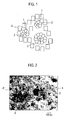
- FIG. 1 is a schematic view of an exhaust gas purifying catalyst of an embodiment of the present invention.
- the exhaust gas purifying catalyst shown in FIG. 1 includes: noble metal particles 1 having catalytic activity; first compounds 2 which support the noble metal particles 1; second compounds 3 different in type from the first compounds; oxides 4 which surround the noble metal particles 1, the first compounds 2 and the second compounds 3.
- the noble metal particles 1 are supported on the first compounds 2.
- the first compounds chemically bond to the noble metal particles 1, function as an anchor agent, and chemically suppress movement of the noble metal particles 1.
- the oxides 4 are interposed between the second compounds 3 and the first compounds 2 which support the noble metal particles 1, and accordingly, by the oxides 4, a plurality of the first compounds are separated from one another, a plurality of the second compounds are separated from one another, or the first compounds 2 and the second compounds are separated from each other. Therefore, the first compounds 2 which support the noble metal particles 1 are suppressed from mutual contact and aggregation, the plurality of second compounds are suppressed from mutual contact and aggregation, or the first compounds 2 and the second compounds are suppressed from contact and aggregation therebetween. The aggregation of the first compounds 2 which support the noble metal particles 1 is suppressed, whereby aggregation of the noble metal particles 1 supported thereon is also suppressed.
- the exhaust gas purifying catalyst of this embodiment is provided with such a catalyst structure, whereby the movement of the noble metal particles 1 is suppressed. Accordingly, the mutual aggregation of the noble metal particles 1 is suppressed, and hence, a particle diameter of the noble metal particles 1 can be maintained to be small.
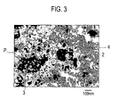
- FIG. 2 shows a microscope photograph of the exhaust gas purifying catalyst of the present invention.
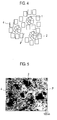
- FIG. 3 shows a sketch of FIG. 2 .
- portions shown black are the first compounds 2 or the second compounds 3
- portions shown white are pores P
- portions shown gray are the oxides 4.
- an exhaust gas purifying catalyst is actually obtained, which includes the first compounds 2, the second compounds 3 and the oxides 4, those being composed in accordance with the present invention, and has the pores P formed therein.
- the noble metal particles 1 cannot be recognized under a magnification of the microscope photograph shown in FIG. 2 since the particle diameter thereof is significantly smaller as compared with those of the first compounds 2 and the like.
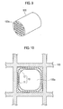
- FIG. 4 is a schematic view of a conventional exhaust gas purifying catalyst for comparison. Note that, in FIG. 4 , the same reference numerals are assigned to the same constituents as those in FIG. 1 .
- the conventional exhaust gas purifying catalyst shown in FIG. 4 is composed in such a manner that the noble metal particles 1 are supported on the first compounds 2, and that the oxides 4 are formed to cover the first compounds.
- the conventional exhaust gas purifying catalyst shown in FIG. 4 is different from the exhaust gas purifying catalyst of the present invention, which is shown in FIG. 1 , in that the second compounds 3 are not provided. In this case, in the conventional exhaust gas purifying catalyst shown in FIG. 4 , the size of the pores P is smaller than in the exhaust gas purifying catalyst of the present invention, which is shown in FIG. 1 .
- FIG. 5 is a microscope photograph of the conventional exhaust gas purifying catalyst shown in FIG. 4 .
- a magnification of the microscope photograph, which is shown in FIG. 5 is set the same as that of the microscope photograph of the exhaust gas purifying catalyst of the present invention, which is shown in FIG. 2 .
- portions shown black are the first compounds 2
- portions shown white are the pores P
- portions shown gray are the oxides 4.
- FIG. 6 shows a sketch of FIG. 5 .
- the size of the pores P is small in the conventional exhaust gas purifying catalyst. This is obvious also based on comparison between the sketch shown in FIG. 3 and the sketch shown in FIG. 6 .
- one of features of the exhaust gas purifying catalyst of this embodiment which is shown in FIG. 1, FIG. 2 and FIG. 3 is that the second compounds having a larger particle diameter than the first compounds are provided.
- the size of the pores can be increased more than in the conventional exhaust gas purifying catalyst, whereby gas diffusibility can be enhanced, and eventually, catalyst performance can be enhanced.
- the catalyst performance is determined by (1) a surface area of the noble metal particles, (2) contact of gas with the noble metal particles, and (3) an effective usage of the contacting gas.
- a structure as mentioned above that is, a structure in which the noble metal particles are supported on the first compounds as the anchor agent, and the first compounds supporting the noble metal particles are surrounded (anchor-surrounded) by the oxides.
- the conventional exhaust gas purifying catalyst has succeeded in restricting the particle diameter of the noble metal to approximately 10 [nm] even after durability test, and in increasing the surface area of the noble metal particles.
- the exhaust gas purifying catalyst with such an anchor-surrounded structure as described above has adopted the structure in which the noble metal-anchor agent as active sites are covered with the oxides as a surrounding material, and accordingly, has had a problem that it becomes difficult for the gas to reach the active sites. Therefore, in order to enhance the gas diffusibility, it is necessary to increase a diameter (volume) of the pores formed by the oxides as the surrounding material.
- the present invention strikes a balance between these two contradictory matters, that is, between the reduction of the particle diameter of the noble metal after the durability test and the increase of the pore volume of the surrounding material. It has been found that, as means for the above, it is effective that the anchor agent on which the noble metal particles are supported has a small particle diameter, that other particles having a larger diameter than the anchor agent are provided, and that the other particles are surrounded together with the anchor agent within the oxides.
- one of requirements for the present invention is that a following inequality should be satisfied: median diameter of first compounds ⁇ median diameter of second compounds.
- the present invention can strike the balance between the reduction of the particle diameter of the noble metal after the durability test and the increase of the pore volume of the surrounding material.
- the gas diffusibility of the exhaust gas purifying catalyst can be enhanced, and eventually, the performance enhancement of the exhaust gas purifying catalyst is achieved.
- first compounds and the second compounds are simultaneously surrounded within the oxides.
- first compounds and the second compounds are independently surrounded within the oxides, that is, in the case of an exhaust gas purifying catalyst in which the first compounds are surrounded within the oxides, the second compounds are surrounded within the oxides independently thereof, and both of the compounds thus surrounded are mixed with each other, the pore volume in the vicinity where the noble metal particles are actually present cannot be increased though the pore volume is large. Accordingly, performance of the exhaust gas purifying catalyst is not high.
- the median diameters of the first compounds and the second compounds were measured by using LA-920 made by HORIBA, Ltd., and the pore volume was measured by a N 2 adsorption method by using ASAP2010 made by Shimadzu Corporation. Moreover, the median diameters refer to D 50 .
- the noble metal effective for purifying the exhaust gas there are mentioned platinum (Pt), palladium (Pd) and rhodium (Rh), and there are preferable combinations of the first compounds, which corresponds to these noble metals.
- the first compounds oxides containing Ce and oxides containing Zr or the like can be used, and in this case, composite oxides thereof can also be used.
- the second compounds are compounds having a promoter function.
- At least one of the first compounds and the second compounds contain plural types of compounds.
- the reason for this is as follows.
- Plural types of the anchor agents (first compounds) which support the noble metal particles are provided, and/or plural types of the second compound particles having a larger particle diameter than the first compounds are provided, whereby a mutual interaction in the noble metal particles or an interaction between the noble metal particles and the second compounds as a promoter is enhanced.
- the effective usage of the contacting gas is performed.
- the second compounds are oxides having an oxygen absorption/release function.
- the promoter there is an oxygen release material. Therefore, by the fact that the second compounds are the oxides having the oxygen absorption/release function, the second compounds effectively function as the promoter. Hence, the catalyst performance can be enhanced.
- the oxides having this oxygen absorption/release function for example, there is an oxide containing Cerium (Ce).
- the median diameter of the first compounds is 300 [nm] or less
- the median diameter of the second compounds is 1000 [nm] or less.
- the median diameter of the first compounds exceeds 300 [nm]
- such a function to keep the noble metal particles small is decreased radically.
- the median diameter of the second compounds becomes larger than 1000 [nm]
- the respective median diameters of the first compounds and the second compounds satisfy such numeric ranges thereof.
- a lower limit of the median diameter of the first compounds is not particularly limited, and can be set at that of a median diameter within a range where the first compounds are industrially producible.
- the median diameter of the first compounds is 200 [nm] or less
- the median diameter of the second compounds is 1000 [nm] or less.
- the median diameter of the first compounds and the median diameter of the second compounds satisfy a relationship of a following expression: median diameter of second compounds / median diameter of first compounds ⁇ 1.2.
- median diameter of the first compounds is 150 [nm]
- the median diameter of the second compounds is 180 [nm] or more.
- a ratio of the median diameter of the second compounds with respect to the median diameter of the first compounds is set at 1.2 or more, whereby the enhancement of the gas diffusibility of the exhaust gas purifying catalyst, which is brought by the fact that the median diameter of the second compounds is larger than the median diameter of the first compounds, can be realized more surely.
- the pore volume in a range where the pore diameter is 0 to 200 [nm], which is measured by the N 2 adsorption method is 0.3 [cc/g] or more.
- a pore diameter effective for the contact between the noble metal particles and the gas is in a range of 200 [nm] or less.
- the pore diameter in this numeric range represents that of pores in the catalyst powder.
- a pore diameter in a range of larger than 200 [nm] represents that of pores in a catalyst coating layer formed on inner walls of a refractory inorganic substrate such as a honeycomb carrier, which partition through holes thereof.
- FIG. 7 is a graph showing an example of pore size distributions, which are measured by the N 2 adsorption method, with regard to the exhaust gas purifying catalyst of the present invention, which includes the second compounds, and the exhaust gas purifying catalyst of the conventional technology, which does not include the second compounds. It is understood that, in comparison with the exhaust gas purifying catalyst of the conventional technology, the exhaust gas purifying catalyst of the present invention has a peak of the pore size distribution on a side where the pore diameter is larger, and has an increased pore volume.
- FIG. 8 is a graph showing a relationship between the pore volume of the exhaust gas purifying catalyst in the range where the pore diameter is 0 to 200 [nm] and a NOx conversion rate as an example of the exhaust gas purification performance. As understood from FIG. 8 , the NOx conversion rate is enhanced as the pore volume of the catalyst is increased.
- the pore volume in the range where the pore diameter is 0 to 200 [nm], which is measured by the N 2 adsorption method is 0.4 [cc/g] or more.
- a combination of the noble metal particles and the first compounds in the exhaust gas purifying catalyst of the present invention can be made so that the noble metal can be Pt and that the first compounds can be oxides containing at least Ce.
- the oxides containing Ce may be not only Ce oxides but also composite oxides of Ce and another transition metal (for example, Zr).
- Another combination of the noble metal and the first compounds in the exhaust gas purifying catalyst of the present invention can be made so that the noble metal can be Pd and that the first compounds can be oxides containing at least Zr.
- the oxides containing Zr may be not only Zr oxides but also composite oxides of Zr and another transition metal (for example, Ce or La).
- Still another combination of the noble metal and the first compounds in the exhaust gas purifying catalyst of the present invention can be made so that the noble metal can be Rh and that the first compounds can be oxides containing at least Zr.
- the oxides containing Zr may be not only Zr oxides but also composite oxides of Zr and another transition metal (for example, La).
- the second compounds can be oxides containing at least Ce.
- the reason for this is as follows.
- the oxides containing Ce are an oxygen absorption/release material, and accordingly, effectively function as the promoter, and can enhance the catalyst performance.
- the oxides containing Ce may be not only Ce oxides but also composite oxides containing another transition material than Ce, for example, zirconium (Zr), praseodymium (Pr) or yttrium (Y).
- Zr zirconium
- Pr praseodymium
- Y yttrium
- the noble metal particles are not present on the second compounds.
- the second compounds a deterioration at the time of impregnating the noble metal particles does not occur in the production process of the catalyst. Moreover, at the time of using the catalyst, it is estimated that the temperature of the noble metal particles is higher than the exhaust gas temperature under measurement when the noble metal particles are purifying the exhaust gas, and it is conceived that the temperature of the noble metal particles rises extremely; however, the second compounds become less likely to be deteriorated by the high temperature.
- the second compounds can also be oxides containing at least one element selected from [Fe, Mn, Co and Ni].
- the reason for this is as follows.
- the oxides containing at least one transition element selected from [Fe, Mn, Co and Ni] effectively function as the promoter, whereby the function to effectively use the contacting gas is enhanced, and accordingly, the catalyst performance can be enhanced.
- the second compounds may be oxides containing one of these transition elements, or may be oxides or composite oxides, which contain two or more thereof.
- the second compounds can also be compounds containing at least one selected from [Ba, Mg and Ca].
- the reason for this is as follows.
- the compounds containing at least one alkaline earth element selected from [Ba, Mg and Ca] are a NOx adsorption material, and thereby effectively function as the promoter, whereby the function to effectively use the contacting gas is enhanced, and accordingly, the catalyst performance can be enhanced.
- an exhaust gas purifying catalyst in which the second compounds contain at least one selected from [Ba, Mg and Ca] has a high effect particularly as a NOx adsorption catalyst.
- a NOx adsorption reaction has extremely high sensitivity to the contact of the gas, and accordingly, the exhaust gas purifying catalyst that enhances the contact of the gas by containing the second compounds in accordance with the present invention can enhance the NOx adsorption reaction.
- the exhaust gas purifying catalyst of the present invention is served for an actual machine in such a manner that powder of the exhaust gas purifying catalyst provided with the above-mentioned requirements is coated on the refractory inorganic substrate such as the honeycomb carrier.
- FIG. 9 is a schematic perspective view of an example of the refractory inorganic substrate coated with the exhaust gas purifying catalyst of the present invention.
- a refractory inorganic substrate 100 shown in FIG. 9 is composed of a refractory inorganic material, has a substantially columnar shape, and has a large number of through holes 100a formed all the way from one end surface thereof to the other end surface thereof. Note that, in FIG. 9 , the through holes 100a are schematically drawn so as to facilitate the understanding of the present invention. Therefore, a shape, dimension and number of the through holes 100a and a thickness of inner walls of the refractory inorganic substrate that partitions the through holes adjacent to one another are different from those of through holes of an actual substrate.
- the powder of the exhaust gas purifying catalyst of the present invention is coated on surfaces of inner walls of the through holes of this refractory inorganic substrate.
- catalyst slurry containing the powder of the exhaust gas purifying catalyst is prepared, and this catalyst slurry is adhered onto surfaces of the inner walls of the refractory inorganic substrate, followed by removal of excessive slurry, and subsequent drying and baking, whereby a catalyst coating layer can be obtained.
- a coating amount of the catalyst just needs to be set at an appropriate amount corresponding to an amount of the noble metal contained in the exhaust gas purifying catalyst.
- the refractory inorganic substrate on which the catalyst coating layer is formed is connected to an exhaust side of an engine of the automobile, and is served for purifying the exhaust gas.
- This catalyst coating layer is provided with structural elements of the exhaust gas purifying catalyst of the present invention.
- the catalyst coating layer formed by coating the above-described powder on the refractory inorganic substrate is composed of a plurality of layers.
- FIG. 10 shows an enlarged cross-sectional view of one through hole 100a in the refractory inorganic substrate 100 of FIG. 9 , which is taken along a cross section perpendicular to a penetrating direction thereof.
- the catalyst coating layer 10 is formed on such an inner wall surface of the refractory inorganic substrate 100.
- This catalyst coating layer is composed in such a manner that two catalyst layers, which are first and second catalyst layers 11 and 12 different from each other in type of the exhaust gas purifying catalyst, are stacked on each other.
- the catalyst coating layer is composed of the plurality of layers different from each other in type of the exhaust gas purifying catalyst, thus making it possible to share functions of the exhaust gas purifying catalyst between the layers.
- a plurality of the functions can be optimized by the respective layers, thus making it possible to enhance the performance of the exhaust gas purifying catalyst as a whole of the catalyst coating layer.
- the exhaust gas purifying catalyst of the present invention is not limited to the example where the plurality of layers are two layers, and may have three or more layers.
- Test 1 the exhaust gas purification performance after the durability test was investigated based on conversion rates.
- Each of these exhaust gas purifying catalysts is composed of catalyst layers coated on inner wall surfaces of a cordierite monolithic substrate as the refractory inorganic substrate.
- the cordierite monolithic substrate on which the catalyst of each of Examples and Comparative examples was formed was mounted on an exhaust system of a gasoline engine with a displacement of 3500 [cc], a catalyst inlet temperature was set at 800 [°C], and the gasoline engine was operated for 50 hours.
- the cordierite monolithic substrate that was subjected to the above-described durability test was mounted on the exhaust system of the gasoline engine with a displacement of 3500 [cc], the catalyst inlet temperature was raised from 150 °C to 500 °C at a rate of 10 °C/minute, and concentrations of HC, CO and NOx in the exhaust gas individually at a catalyst inlet and a catalyst outlet at that time were measured. Then, rates of HC conversion, CO conversion and NOx conversion were calculated in accordance with the following expressions.
- HC conversion rate % catalyst inlet HC conversion - catalyst outlet HC concentration / catalyst inlet HC concentration ⁇ 100
- CO conversion rate % catalyst inlet CO concentration - catalyst outlet CO concentration / catalyst inlet CO concentration ⁇ 100
- NOx conversion rate % catalyst inlet NOx concentration - catalyst outlet NOx concentration / catalyst inlet NOx concentration ⁇ 100
- Rh nitrate solution was impregnated into La-containing ZrO 2 powder with a specific surface area of 70 [m 2 /g], and was supported thereon so that a supporting concentration of Rh could become 1.0 [wt%].
- An obtained solution was dried at 150 [°C] day and night, and was thereafter baked at 400 [°C] for one hour, whereby Rh (1.0 [wt%])/La-containing ZrO 2 powder (hereinafter, referred to as "powder A”) was obtained.
- This powder A was milled to become Rh/La-ZrO 2 powder with a median diameter (D 50 ) of 148 [nm].
- powder B Zr-containing CeO 2 powder with a specific surface area of 80 [m 2 /g] was milled, whereby powder (hereinafter, referred to as "powder B") in which a median diameter (D 50 ) was set at 231 [nm] was obtained.
- boehmite, nitric acid and water were mixed together, and were stirred for 1 [hr].
- the above-described powder A and the above-described powder B were slowly poured into this liquid, and an obtained resultant was further stirred for 2 [hr].
- the resultant was dried at 80 [°C] for 3 [hr] under reduced pressure.
- the resultant was baked at 550 [°C] for 3 [hr] in air, whereby powder C was obtained.
- a weight ratio of a total amount (powder A + powder B) of the powder A and the powder B and Al 2 O 3 was 70: 30.
- a ratio of the powder A and the powder B was 80: 20 in terms of the weight ratio.
- the obtained catalyst slurry was adhered onto a cordierite monolithic substrate (0.12 [L], 400 cells), excessive slurry in the cells was removed by an air flow, and the catalyst slurry was dried at 130 [°C], followed by baking at 400 [°C] for one hour, whereby a catalyst layer with a coating layer of 200 [g/L] was obtained.
- a production process of the catalyst of Example 2 is the same as that of Example 1 except that, in the above-described production process of the catalyst of Example 1, the supporting concentration of Rh in the powder A was set at 1.4 [wt%], and the ratio of the total amount (powder A + powder B) of the powder A and the powder B and Al 2 O 3 was set at 50: 50.
- Comparative example 1 is an example where the second compounds are not provided.
- Rh nitrate solution was supported on La-containing ZrO 2 powder with a specific surface area of 70 [m 2 /g] so that a supporting concentration or Rh could become 0.8 [wt%].
- An obtained solution was dried at 150 [°C] day and night, and was thereafter baked at 400 [°C] for one hour, whereby Rh (0.8 [wt%])/La-containing ZrO 2 powder (hereinafter, referred to as "powder D”) was obtained.
- This powder D was milled to become Rh/La-ZrO 2 powder with a median diameter (D 50 ) of 148 [nm].
- the obtained catalyst slurry was adhered onto a cordierite monolithic substrate (0.12 [L], 400 cells), excessive slurry in the cells was removed by an air flow, and the catalyst slurry was dried at 130 [°C], followed by baking at 400 [°C] for one hour, whereby a catalyst layer with a coating layer of 200 [g/L] was obtained.
- Comparative example 2 is an example where the first compounds and the second compounds are surrounded by the oxides independently of each other.
- Rh nitrate solution was supported on La-containing ZrO 2 powder with a specific surface area of 70 [m 2 /g] so that a supporting concentration or Rh could become 1.0 [wt%].
- An obtained solution was dried at 150 [°C] day and night, and was thereafter baked at 400 [°C] for one hour, whereby Rh (1.0 [wt%])/La-containing ZrO 2 powder (hereinafter, referred to as "powder F”) was obtained.
- This powder F was milled to become Rh/La-ZrO 2 powder with a median diameter (D 50 ) of 148 [nm].
- powder H Zr-containing CeO 2 powder with a specific surface area of 80 [m 2 /g] was milled, whereby powder (hereinafter, referred to as "powder H") with a median diameter (D 50 ) of 231 [nm] was obtained.
- the obtained catalyst slurry was adhered onto a cordierite monolithic substrate (0.12 [L], 400 cells), excessive slurry in the cells was removed by an air flow, and the catalyst slurry was dried at 130 [°C], followed by baking at 400 [°C] for one hour, whereby a catalyst layer with a coating layer of 200 [g/L] was obtained.
- Comparative example 3 is an example where the median diameter of the second compounds is smaller than the median diameter of the first compounds.
- Rh nitrate solution was impregnated into La-containing ZrO 2 powder with a specific surface area of 70 [m 2 /g], and was supported thereon so that a supporting concentration of Rh could become 1.0 [wt%].
- An obtained solution was dried at 150 [°C] day and night, and was thereafter baked at 400 [°C] for one hour, whereby Rh (1.0 [wt%])/La-containing ZrO 2 powder (powder A) was obtained.
- This powder A was milled to become Rh/La-ZrO 2 powder with a median diameter (D 50 ) of 148 [nm].
- powder BB Zr-containing CeO 2 powder with a specific surface area of 80 [m 2 /g] was milled, whereby powder (hereinafter, referred to as "powder BB") in which a median diameter (D 50 ) was set at 117 [nm] was obtained.
- powder CC was obtained.
- a ratio of a total amount (powder A + powder BB) of the powder A and the powder BB and Al 2 O 3 was 70: 30 in terms of the weight ratio.
- a ratio of the powder A and the powder BB was 80: 20 in terms of the weight ratio.
- the obtained catalyst slurry was adhered onto a cordierite monolithic substrate (0.12 [L], 400 cells), excessive slurry in the cells was removed by an air flow, and the catalyst slurry was dried at 130 [°C], followed by baking at 400 [°C] for one hour, whereby a catalyst layer with a coating layer of 200 [g/L] was obtained.
- Table 1 shows characteristics and catalyst performances in the catalysts of Example 1, Example 2, Comparative example 1, Comparative example 2 and Comparative example 3, which are mentioned above.
- Noble metal First compound Second compound Compounds A+B Compound C (ratio) Oxide Powder pore volume (cc/g) NOx conversion rate after durability test (%) Type Mean particle diameter (nm)
- Type Mean particle diameter (nm) Type Example 1 Rh Zr-La-O x 148 Ce-Zr-O x 231 70:30 Al 2 O 3 0.41 96
- Example 1 and Example 2 since the second compounds having a larger median diameter than the first compounds are provided the NOx conversion rates were higher in comparison with Comparative ecample 1 in which the second compounds are not provided and with Comparative example 2 where the first compounds and the second compounds are supported within the oxides independently of each other.
- Comparative example 2 though the second compounds are provided, the second compounds are supported within the oxides independently of the first compounds, and accordingly, the NOx conversion rate was inferior to that in Example 1 and Example 2 though the pore volume became higher than that of Comparative example 1.
- the reason why Comparative example 2 has higher performance than Comparative example 1 is conceived to be that the second compounds function as the promoter.
- Comparative example 3 though the first compounds have the same median diameter as that in Example 1, the second compounds have a smaller median diameter than the median diameter of the first compounds. Accordingly, Comparative example 3 is poor in the effect of expanding the pore volume of the catalyst powder, which is brought by the presence of the second compounds, and hence, the powder pore volume and NOx conversion rate thereof were substantially the same as those in Comparative example 1.
- Comparative example 3 and Example 1 obviously, by the fact that the second compounds having a larger median diameter than the first compounds are provided in accordance with the present invention, the pore volume of the catalyst powder is expanded, and eventually, the NOx conversion rate is enhanced.
- Example 3 is an example where plural types of the first compounds are provided.
- Dinitrodiamine Pt salt was supported on Zr-containing CeO 2 powder with a specific surface area of 80 [m 2 /g] so that a supporting concentration of Pt could become 1.0 [wt%].
- An obtained solution was dried at 150 [°C] day and night, and was thereafter baked at 400 [°C] for one hour, whereby Pt (1.0 [wt%])/Zr-containing CeO 2 powder (hereinafter, referred to as "powder J”) was obtained.
- This powder J was milled to become Pt/Zr-CeO 2 powder with a median diameter (D 50 ) of 131 [nm].
- boehmite, nitric acid and water were mixed together, and were stirred for 1 [hr].
- the powder A, the powder B and the powder J were slowly poured into this liquid, and an obtained resultant was further stirred for 2 [hr].
- the resultant was dried at 80 [°C] for 3 [hr] under reduced pressure.
- powder K was obtained.
- a ratio of a total amount (powder A + powder B + powder J) of the powder A, the powder B and the powder J and Al 2 O 3 was 70: 30 in terms of the weight ratio.
- a ratio of the powder A, the powder B and the powder J was 40: 20: 40.
- the obtained catalyst slurry was adhered onto a cordierite monolithic substrate (0.12 [L], 400 cells), excessive slurry in the cells was removed by an air flow, and the catalyst slurry was dried at 130 [°C], followed by baking at 400 [°C] for one hour, whereby a catalyst layer with a coating layer of 200 [g/L] was obtained.
- Example 3 is an example where plural types of the first compounds are provided, and plural types of the second compounds are provided.
- Pr-containing CeO 2 with a specific surface area of 80 [m 2 /g] was milled and turned into powder with a median diameter (D 50 ) of 228 [nm] (powder L).
- boehmite, nitric acid and water were mixed together, and were stirred for 1 [hr].
- the powder A, the powder B, the powder J and the powder L were slowly poured into this liquid, and an obtained resultant was further stirred for 2 [hr].
- the resultant was dried at 80 [°C] for 3 [hr] under reduced pressure.
- the obtained catalyst slurry was adhered onto a cordierite monolithic substrate (0.12 [L], 400 cells), excessive slurry in the cells was removed by an air flow, and the catalyst slurry was dried at 130 [°C], followed by baking at 400 [°C] for one hour, whereby a catalyst layer with a coating layer of 200 [g/L] was obtained.
- Example 5 is an example where plural types of the first compounds are provided. Moreover, as the second compounds, not the Zr-containing CeO 2 powder (powder B) in Example 3 but Ce and Y-containing ZrO 2 powder (hereinafter, referred to as "powder N”) was used.
- Pd nitrate salt was supported on Ce and La-containing ZrO 2 powder with a specific surface area of 70 [m 2 /g] so that a supporting concentration of Pd could become 1.0 [wt%].
- An obtained solution was dried at 150 [°C] day and night, and was thereafter baked at 400 [°C] for one hour, whereby Pd (1.0 [wt%])/Ce, La-containing ZrO 2 powder (hereinafter, referred to as "powder O”) was obtained.
- This powder O was milled to become Pd/Ce, La-ZrO 2 powder with a median diameter (D 50 ) of 131 [nm].
- boehmite, nitric acid and water were mixed together, and were stirred for 1 [hr].
- the powder J, the powder O and the powder N were slowly poured into this liquid, and an obtained resultant was further stirred for 2 [hr].
- the resultant was dried at 80 [°C] for 3 [hr] under reduced pressure.
- the resultant was baked at 550 [°C] for 3 [hr] in air, whereby powder P was obtained.
- a weight ratio of a total amount (powder J + powder O + powder N) of the powder J, the powder O and the powder N and Al 2 O 3 was 70: 30.
- a ratio of the powder J, the powder N and the powder O was 40: 20: 40 in terms of the weight ratio.
- the obtained catalyst slurry was adhered onto a cordierite monolithic substrate (0.12 [L], 400 cells), excessive slurry in the cells was removed by an air flow, and the catalyst slurry was dried at 130 [°C], followed by baking at 400 [°C] for one hour, whereby a catalyst layer with a coating layer of 200 [g/L] was obtained.
- Example 6 is an example where plural types of the first compounds are provided.
- Boehmite, nitric acid and water were mixed together, and were stirred for 1 [hr].
- the powder A, the powder O and the powder B were slowly poured into this liquid, and an obtained resultant was further stirred for 2 [hr].
- the resultant was dried at 80 [°C] for 3 [hr] under reduced pressure.
- the resultant was baked at 550 [°C] for 3 [hr] in air, whereby powder Q was obtained.
- a ratio of a total amount (powder A + powder O + powder B) of the powder A, the powder O and the powder B and Al 2 O 3 was 70: 30.
- a ratio of the powder A, the powder B and the powder O was 40: 20: 40.
- the obtained catalyst slurry was adhered onto a cordierite monolithic substrate (0.12 [L], 400 cells), excessive slurry in the cells was removed by an air flow, and the catalyst slurry was dried at 130 [°C], followed by baking at 400 [°C] for one hour, whereby a catalyst layer with a coating layer of 200 [g/L] was obtained.
- Table 2 shows characteristics and catalyst performances in the catalysts of Examples 3 to 6, which are mentioned above. Note that, in each of Examples 3 to 6, the weight ratio of the total amount of the first compounds and the second compounds and the oxides (Al 2 O 3 ) was 70: 30. However, the catalyst of the present invention is not limited to those with such a weight ratio.
- Examples 7 to 19 are examples where the median diameter of the first compounds, the median diameter of the second compounds and the pore volume of the catalyst powder were set at a variety of values. These median diameters were adjusted by milling the first compounds and the second compounds. Note that types of the noble metal particles, the first compounds and the second compounds in the catalysts of Examples 7 to 19 are the same as those in Example 1.
- Table 3 shows the types of the noble metal, the types and median diameters of the first compounds, the types and median diameters of the second compounds, the pore volumes of the catalyst powder and purification performances in catalysts of Examples 7 to 19 together with such values of Example 1 for comparison.
- Noble metal First compound Second compound Ratio as: (mean particle diameter of second compound) / (mean particle diameter of first compound) Oxide Powder pore volume (cc/g) NOx conversion rate after durability test (%)
- Type Mean particle diameter (nm) Type Mean particle diameter (nm)
- the catalyst performance after the durability test was enhanced by the fact that the median diameter of the first compounds was 300 [nm] or less, and that the median diameter of the second compounds was 1000 [nm] or less. Moreover, the catalyst performance after the durability test was further enhanced by the tact that the median diameter of the first compounds was 200 [nm] or less, and that the median diameter of the second compounds was 1000 [nm] or less.
- the catalyst performance after the durability test was enhanced by the fact that the pore volume in the range where the pore diameter was 0 to 200 [nm] in the catalyst was 0.3 [cc/g] or more. Still further, the catalyst performance after the durability test was further enhanced by the fact that the pore volume was 0.4 [cc/g] or more.
- Examples 20 to 23 are examples where the second compounds are the oxides containing at least one element selected from [Fe, Mn, Co and Ni]. Note that Examples 20 to 23 are the same as Example 1 except the types of the second compounds and the median diameters adjusted by milling the second compounds.
- Table 4 shows types of the noble metal, types and median diameters of the first compounds, the types and median diameters of the second compounds, pore volumes of the catalyst powder and catalyst performances in catalysts of Examples 20 to 23 together with such values of Example 1 for comparison.
- Type Mean particle diameter (nm) Type Example 1 Rh Zr-La-O x 148 Ce-Zr-O x 231 Al 2 O 3 0.41 96
- the exhaust gas purifying catalyst of the present invention exhibited excellent purification performance after the durability test.
- Test 1 the exhaust gas purification performance after the durability test was investigated based on the conversion rates when the air-fuel ratio was changed from the lean side to the rich side.
- Exhaust gas purifying catalysts of Examples 24 to 29 were prepared as below. These exhaust gas purifying catalysts are composed of catalyst layers coated on the inner wall surfaces of the cordierite monolithic substrates as the refractory inorganic substrates.
- the cordierite monolithic substrate on which the catalyst of each of Examples and Comparative examples was formed was mounted on an exhaust system of a gasoline engine with a displacement of 3500 [cc], a catalyst inlet temperature was set at 700 [°C], and the gasoline engine was operated for 50 hours.
- a test temperature was set at 300 [°C] to 350 [°C].
- Examples 24 to 27 are examples where the second compounds are the oxides containing Ce or the oxides containing at least one element selected from [Ba, Mg and Ca]. Note that, in Examples 24 to 27, the powder J was used in place of the powder A in Example 1. Moreover, as the second compounds, there were used the oxides containing Ce or the oxides containing at least one element selected from [Ba, Mg and Ca], and the median diameters thereof were adjusted by milling the oxides. Besides the above, the same conditions as those in Example 1 were used.
- Table 5 shows types of the noble metal, types and median diameters of the first compounds, the types and median diameters of the second compounds, pore volumes of the catalyst powder and NOx conversion rates after the durability test in catalysts of Examples 24 to 27.
- Type Example 24 Pt Ce-Zr-O x 131 Ce-Zr-O x 231 Al 2 O 3 0.41 23
- Example 25 Pt Ce-Zr-O x 131 BaCO 3 206 Al 2 O 3 0.40 78
- Example 26 Pt Ce-Zr-O x 131 MgCO 3 211 Al 2 O 3 0.39 54
- the exhaust gas purifying catalyst of the present invention had excellent characteristics as a NOx adsorption catalyst.
- Example 28 is an example where the catalyst coating layer formed by coating the powder of the exhaust gas purifying catalyst on the refractory inorganic substrate is composed of a plurality of layers.
- catalyst slurry was obtained, in which the powder A of Example 1 was replaced by the powder J.
- the obtained catalyst slurry was adhered onto a cordierite monolithic substrate (0.12 [L], 400 cells), excessive slurry in the cells was removed by an air flow, and the catalyst slurry was dried at 130 [°C], followed by baking at 400 [°C] for one hour, whereby a catalyst layer with a coating layer of 200 [g/L] was obtained.
- Example 1 the catalyst slurry of Example 1 was adhered onto the above-described catalyst layer, excessive slurry in the cells was removed by an air flow, and the catalyst slurry was dried at 130 [°C], followed by baking at 400 [°C] for one hour, whereby a catalyst layer with a coating layer of 100 [g/L] was obtained.
- Example 29 is an example where the catalyst coating layer formed by coating the powder of the exhaust gas purifying catalyst on the refractory inorganic substrate is composed of a plurality of layers in a similar way to Example 28. Note that Example 29 is different from Example 28 in type of the coating layers.
- catalyst slurry was obtained, in which the powder A of Example 1 was replaced by the powder O.
- the obtained catalyst slurry was adhered onto a cordierite monolithic substrate (0.12 [L], 400 cells), excessive slurry in the cells was removed by an air flow, and the catalyst slurry was dried at 130 [°C], followed by baking at 400 [°C] for one hour, whereby a catalyst layer with a coating layer of 200 [g/L] was obtained.
- Example 1 the slurry of Example 1 was adhered onto the above-described catalyst layer, excessive slurry in the cells was removed by an air flow, and the slurry was dried at 130 [°C], followed by baking at 400 [°C] for one hour, whereby a catalyst layer with a coating layer of 100 [g/L] was obtained.
- Table 6 shows types of the respective coating layers and purification performances of the catalysts in Example 28 and Example 29. [Table 6] First catalyst layer (inner layer) Second catalyst layer (surface layer) NOx conversion rate (%) Example 28 Pt powder of Example 3 Rh powder of Example 1 99 Example 29 Pd powder of Example 5 Rh powder of Example 1 98
- Example 28 and Example 29 had an enhanced NOx conversion rate and excellent exhaust gas purification performance after the durability test since the plurality of catalyst layers were provided.
- the exhaust gas purifying catalyst of the present invention is superior to the conventional ones in exhaust gas purification performance, and accordingly, while maintaining the purification performance for the exhaust gas at a certain level or more, can reduce the usage amount of the noble metal, and can be suitably used for the exhaust gas system of the automobile.
Landscapes
- Chemical & Material Sciences (AREA)
- Engineering & Computer Science (AREA)
- Materials Engineering (AREA)
- Chemical Kinetics & Catalysis (AREA)
- Organic Chemistry (AREA)
- Health & Medical Sciences (AREA)
- Combustion & Propulsion (AREA)
- Biomedical Technology (AREA)
- Environmental & Geological Engineering (AREA)
- Analytical Chemistry (AREA)
- General Chemical & Material Sciences (AREA)
- Oil, Petroleum & Natural Gas (AREA)
- Catalysts (AREA)
- Exhaust Gas Treatment By Means Of Catalyst (AREA)
Abstract

Description
- The present invention relates to an exhaust gas purifying catalyst suitable for application to treatment for purifying exhaust gas discharged from an internal combustion engine.
- In recent years, an exhaust gas purifying catalyst, in which particles of noble metal such as platinum (Pt) and rhodium (Rh) are supported on a support of metal oxide such as alumina (Al2O3), has been being widely used in order to remove harmful substances such as a hydrocarbon (HC)-based compound, carbon monoxide (CO) and nitrogen oxide (NOx), which are contained in exhaust gas discharged from an internal combustion engine. In the conventional exhaust gas purifying catalyst, a large amount of such noble metal particles is used in order to enhance durability of the noble metal particles against variations of an ambient atmosphere. However, it is not desirable to use the large amount of noble metal particles from a viewpoint of protecting the earth's resources.
- One method for reducing such a usage amount of the noble metal while maintaining purification performance for the exhaust gas at a certain level or more is to reduce a particle diameter of the noble metal particles. If the particle diameter of the noble metal particles is reduced, then a specific surface area thereof is increased. Accordingly, it is sufficient that the usage amount of noble metal for obtaining desired purification performance of the catalyst is small. However, when the particle diameter of the noble metal particles is small, the noble metal particles mutually cause thermal aggregation (sintering) owing to a high-temperature use thereof and a long-term use thereof, and accordingly, there is an apprehension that the durability of the noble metal particles may be decreased.
- In this connection, an exhaust gas purifying catalyst has been developed, which has a structure in which the noble metal particles are supported on first compounds, and the first compounds supporting the noble metal particles thereon are surrounded by second compounds, whereby the first compounds, on which the noble metal is supported, are separated from one another by the second compounds (Patent Document 1). In the exhaust gas purifying catalyst having such a structure, the noble metal particles are supported on the first compounds, and the noble metal particles are thereby chemically fixed to the first compounds, whereby movement and aggregation of the noble metal particles are suppressed. Moreover, the first compounds, which support the noble metal particles thereon, are physically separated from one another by the second compounds, whereby the first compounds, which support the noble metal thereon, are suppressed from mutual contact and aggregation. In such a way, the noble metal particles are prevented from being aggregated after durability test, whereby the durability thereof can be enhanced.
-
- Patent Document 1: Pamphlet of International Publication
WO 2007/052627 - The recent demands for the protection of the earth's resources and protection of the earth's environment have been enhanced more and more, and have not been ceased at all. Therefore, the exhaust gas purifying catalyst having excellent characteristics, which is described in the above-mentioned
Patent Document 1, is also required to have further enhancement of the characteristics and further decrease of the usage amount of the noble metal. - Here, with regard to the exhaust gas purifying catalyst described in the
foregoing Patent Document 1, it has been necessary to reduce an amount of the noble metal particles supported on the first compounds in order to maintain the particle diameter of the noble metal particles to be small. Therefore, this exhaust gas purifying catalyst has reduced a particle diameter of the first compounds. However, when the particle diameter of the first compounds is small, then in some case, a pore volume of the exhaust gas purifying catalyst, which serves as an index of a size of pores thereof, has been reduced, and gas diffusibility thereof has been lowered. Therefore, though the exhaust gas purifying catalyst has had such a structure to maintain the particle diameter of the noble metal particles to be small, enhancement of exhaust gas purification performance, which is brought by reducing the particle diameter of the noble metal particles, has not been sufficient in some case. - In order to solve the foregoing problem, an exhaust gas purifying catalyst according to the present invention includes: a noble metal particle; a first compound which supports the noble metal particle; a second compound different in type from the first compound; and an oxide which surrounds the noble metal particle, the first compound and the second compound, wherein a median diameter of the first compound and a median diameter of the second compound satisfy a relationship of a following inequality:

- In accordance with the exhaust gas purifying catalyst according to the present invention, in the structure in which the noble metal particles can be maintained to be small, the gas diffusibility can be enhanced owing to the presence of the second compounds having a large particle diameter, whereby it becomes possible to enhance such an exhaust gas purification capability.
-
- [
Fig. 1] FIG. 1 is a schematic view of an exhaust gas purifying catalyst of an embodiment of the present invention. - [
Fig. 2] FIG. 2 is a microscope photograph of the exhaust gas purifying catalyst of the present invention. - [
Fig. 3] FIG. 3 is a sketch ofFIG. 2 . - [
Fig. 4] FIG. 4 is a schematic view of a conventional exhaust gas purifying catalyst. - [
Fig. 5] FIG. 5 is a microscope photograph of the conventional exhaust gas purifying catalyst. - [
Fig. 6] FIG. 6 is a sketch ofFIG. 5 . - [
Fig. 7] FIG. 7 is a graph showing an example of pore size distributions in the exhaust gas purifying catalyst of the present invention and the conventional exhaust gas purifying catalyst, which are obtained by a N2 adsorption method. - [
Fig. 8] FIG. 8 is a graph showing a relationship between a pore volume of the exhaust gas purifying catalyst in a range where a pore diameter is 0 to 200 [nm] and a NOx conversion rate as an example of exhaust gas purification performance. - [
Fig. 9] FIG. 9 is a schematic perspective view of an example of a refractory inorganic substrate coated with the exhaust gas purifying catalyst of the present invention. - [
Fig. 10]FIG. 10 is an enlarged cross-sectional view of one pore of the refractory inorganic substrate, which is taken along a cross section perpendicular to a penetration direction thereof. - A description is made of an embodiment of an exhaust gas purifying catalyst of the present invention while using the drawings.
-
FIG. 1 is a schematic view of an exhaust gas purifying catalyst of an embodiment of the present invention. The exhaust gas purifying catalyst shown inFIG. 1 includes:noble metal particles 1 having catalytic activity;first compounds 2 which support thenoble metal particles 1;second compounds 3 different in type from the first compounds;oxides 4 which surround thenoble metal particles 1, thefirst compounds 2 and thesecond compounds 3. - The
noble metal particles 1 are supported on thefirst compounds 2. In such a way, the first compounds chemically bond to thenoble metal particles 1, function as an anchor agent, and chemically suppress movement of thenoble metal particles 1. - In addition, the
oxides 4 are interposed between thesecond compounds 3 and thefirst compounds 2 which support thenoble metal particles 1, and accordingly, by theoxides 4, a plurality of the first compounds are separated from one another, a plurality of the second compounds are separated from one another, or thefirst compounds 2 and the second compounds are separated from each other. Therefore, thefirst compounds 2 which support thenoble metal particles 1 are suppressed from mutual contact and aggregation, the plurality of second compounds are suppressed from mutual contact and aggregation, or thefirst compounds 2 and the second compounds are suppressed from contact and aggregation therebetween. The aggregation of thefirst compounds 2 which support thenoble metal particles 1 is suppressed, whereby aggregation of thenoble metal particles 1 supported thereon is also suppressed. The exhaust gas purifying catalyst of this embodiment is provided with such a catalyst structure, whereby the movement of thenoble metal particles 1 is suppressed. Accordingly, the mutual aggregation of thenoble metal particles 1 is suppressed, and hence, a particle diameter of thenoble metal particles 1 can be maintained to be small. -
FIG. 2 shows a microscope photograph of the exhaust gas purifying catalyst of the present invention. Moreover,FIG. 3 shows a sketch ofFIG. 2 . InFIG. 2 , portions shown black are thefirst compounds 2 or thesecond compounds 3, portions shown white are pores P, and portions shown gray are theoxides 4. As understood fromFIG. 2 , an exhaust gas purifying catalyst is actually obtained, which includes thefirst compounds 2, thesecond compounds 3 and theoxides 4, those being composed in accordance with the present invention, and has the pores P formed therein. Note that thenoble metal particles 1 cannot be recognized under a magnification of the microscope photograph shown inFIG. 2 since the particle diameter thereof is significantly smaller as compared with those of thefirst compounds 2 and the like. -
FIG. 4 is a schematic view of a conventional exhaust gas purifying catalyst for comparison. Note that, inFIG. 4 , the same reference numerals are assigned to the same constituents as those inFIG. 1 . The conventional exhaust gas purifying catalyst shown inFIG. 4 is composed in such a manner that thenoble metal particles 1 are supported on thefirst compounds 2, and that theoxides 4 are formed to cover the first compounds. The conventional exhaust gas purifying catalyst shown inFIG. 4 is different from the exhaust gas purifying catalyst of the present invention, which is shown inFIG. 1 , in that thesecond compounds 3 are not provided. In this case, in the conventional exhaust gas purifying catalyst shown inFIG. 4 , the size of the pores P is smaller than in the exhaust gas purifying catalyst of the present invention, which is shown inFIG. 1 . -
FIG. 5 is a microscope photograph of the conventional exhaust gas purifying catalyst shown inFIG. 4 . A magnification of the microscope photograph, which is shown inFIG. 5 , is set the same as that of the microscope photograph of the exhaust gas purifying catalyst of the present invention, which is shown inFIG. 2 . InFIG. 2 , portions shown black are thefirst compounds 2, portions shown white are the pores P, and portions shown gray are theoxides 4. Moreover,FIG. 6 shows a sketch ofFIG. 5 . Based on comparison between the microscope photograph of the conventional exhaust gas purifying catalyst, which is shown inFIG. 5 , and the microscope photograph of the exhaust gas purifying catalyst of the present invention, which is shown inFIG. 2 , it is confirmed that the size of the pores P is small in the conventional exhaust gas purifying catalyst. This is obvious also based on comparison between the sketch shown inFIG. 3 and the sketch shown inFIG. 6 . - In comparison with the conventional exhaust gas purifying catalyst shown in
FIG. 4, FIG. 5 andFIG. 6 , one of features of the exhaust gas purifying catalyst of this embodiment, which is shown inFIG. 1, FIG. 2 andFIG. 3 is that the second compounds having a larger particle diameter than the first compounds are provided. In such a way, in this embodiment, the size of the pores can be increased more than in the conventional exhaust gas purifying catalyst, whereby gas diffusibility can be enhanced, and eventually, catalyst performance can be enhanced. - The above-described effects by the second compounds are more specifically described. The catalyst performance is determined by (1) a surface area of the noble metal particles, (2) contact of gas with the noble metal particles, and (3) an effective usage of the contacting gas. Here, in the conventional exhaust gas purifying catalyst shown in
FIG. 4 and FIG. 5 , in order to make it possible to maintain a predetermined favorable surface area of the noble metal particles even after use of the catalyst at a high temperature for a long time, there has been adopted a structure as mentioned above, that is, a structure in which the noble metal particles are supported on the first compounds as the anchor agent, and the first compounds supporting the noble metal particles are surrounded (anchor-surrounded) by the oxides. In such a way, the conventional exhaust gas purifying catalyst has succeeded in restricting the particle diameter of the noble metal to approximately 10 [nm] even after durability test, and in increasing the surface area of the noble metal particles. - However, the exhaust gas purifying catalyst with such an anchor-surrounded structure as described above has adopted the structure in which the noble metal-anchor agent as active sites are covered with the oxides as a surrounding material, and accordingly, has had a problem that it becomes difficult for the gas to reach the active sites. Therefore, in order to enhance the gas diffusibility, it is necessary to increase a diameter (volume) of the pores formed by the oxides as the surrounding material.
- As a result of an assiduous study of the inventors, it has been found out that there is a correlation relationship between a particle diameter of the first compounds as the anchor agent and the volume of the pores formed by the oxides as the surrounding material. In other words, when the particle diameter of the anchor agent is increased, such a pore volume of the surrounding material that covers the anchor agent is increased. However, when the particle diameter of the anchor agent is simply increased, an amount of the noble metal present on one particle of the anchor agent is increased. In this case, after the durability test, the noble metal particles on a surface of the particle of the anchor agent move and aggregate on the surface, and then become one noble metal particle. Accordingly, as a result, the noble metal particles become a large noble metal particle. This brings about a decrease of the surface area of the noble metal particles.
- The present invention strikes a balance between these two contradictory matters, that is, between the reduction of the particle diameter of the noble metal after the durability test and the increase of the pore volume of the surrounding material. It has been found that, as means for the above, it is effective that the anchor agent on which the noble metal particles are supported has a small particle diameter, that other particles having a larger diameter than the anchor agent are provided, and that the other particles are surrounded together with the anchor agent within the oxides. In this connection, one of requirements for the present invention is that a following inequality should be satisfied:
median diameter of first compounds < median diameter of second compounds.
By this requirement, the present invention can strike the balance between the reduction of the particle diameter of the noble metal after the durability test and the increase of the pore volume of the surrounding material. Hence, while favorably maintaining the suppression of the aggregation of the noble metal particles, the gas diffusibility of the exhaust gas purifying catalyst can be enhanced, and eventually, the performance enhancement of the exhaust gas purifying catalyst is achieved. - An important point of the present invention is that the first compounds and the second compounds are simultaneously surrounded within the oxides. In the case where the first compounds and the second compounds are independently surrounded within the oxides, that is, in the case of an exhaust gas purifying catalyst in which the first compounds are surrounded within the oxides, the second compounds are surrounded within the oxides independently thereof, and both of the compounds thus surrounded are mixed with each other, the pore volume in the vicinity where the noble metal particles are actually present cannot be increased though the pore volume is large. Accordingly, performance of the exhaust gas purifying catalyst is not high.
- Note that the median diameters of the first compounds and the second compounds were measured by using LA-920 made by HORIBA, Ltd., and the pore volume was measured by a N2 adsorption method by using ASAP2010 made by Shimadzu Corporation. Moreover, the median diameters refer to D50.
- As the noble metal effective for purifying the exhaust gas, there are mentioned platinum (Pt), palladium (Pd) and rhodium (Rh), and there are preferable combinations of the first compounds, which corresponds to these noble metals. Moreover, as the first compounds, oxides containing Ce and oxides containing Zr or the like can be used, and in this case, composite oxides thereof can also be used. Moreover, preferably, the second compounds are compounds having a promoter function.
- In the exhaust gas purifying catalyst of the present invention, preferably, at least one of the first compounds and the second compounds contain plural types of compounds. The reason for this is as follows. Plural types of the anchor agents (first compounds) which support the noble metal particles are provided, and/or plural types of the second compound particles having a larger particle diameter than the first compounds are provided, whereby a mutual interaction in the noble metal particles or an interaction between the noble metal particles and the second compounds as a promoter is enhanced. Thus, in the above described determinant factors of the catalyst performance, (3) the effective usage of the contacting gas is performed.
- Preferably, the second compounds are oxides having an oxygen absorption/release function. As an example of the promoter, there is an oxygen release material. Therefore, by the fact that the second compounds are the oxides having the oxygen absorption/release function, the second compounds effectively function as the promoter. Hence, the catalyst performance can be enhanced. As the oxides having this oxygen absorption/release function, for example, there is an oxide containing Cerium (Ce).
- More preferably, the median diameter of the first compounds is 300 [nm] or less, and the median diameter of the second compounds is 1000 [nm] or less. When the median diameter of the first compounds exceeds 300 [nm], such a function to keep the noble metal particles small is decreased radically. Moreover, when the median diameter of the second compounds becomes larger than 1000 [nm], it becomes difficult to surround the second compounds by the oxides as the surrounding material simultaneously with the first compounds. Hence, in addition to that the relationship where the median diameter of the second compounds is larger than the median diameter of the first compounds is satisfied, preferably, the respective median diameters of the first compounds and the second compounds satisfy such numeric ranges thereof. Note that a lower limit of the median diameter of the first compounds is not particularly limited, and can be set at that of a median diameter within a range where the first compounds are industrially producible.
- More preferably, the median diameter of the first compounds is 200 [nm] or less, and the median diameter of the second compounds is 1000 [nm] or less. By the fact that the median diameter of the first compounds is 200 [nm] or less, an amount of the noble metal supported on one first compound particle can be reduced, and hence, the decrease of the exhaust gas purifying performance, which is caused by the aggregation of the noble metal particles, can be effectively suppressed.
- More preferably, the median diameter of the first compounds and the median diameter of the second compounds satisfy a relationship of a following expression:

For example, if the median diameter of the first compounds is 150 [nm], then the median diameter of the second compounds is 180 [nm] or more. A ratio of the median diameter of the second compounds with respect to the median diameter of the first compounds is set at 1.2 or more, whereby the enhancement of the gas diffusibility of the exhaust gas purifying catalyst, which is brought by the fact that the median diameter of the second compounds is larger than the median diameter of the first compounds, can be realized more surely. - More preferably, in the exhaust gas purifying catalyst of the present invention, the pore volume in a range where the pore diameter is 0 to 200 [nm], which is measured by the N2 adsorption method, is 0.3 [cc/g] or more. In the exhaust gas purifying catalyst, a pore diameter effective for the contact between the noble metal particles and the gas is in a range of 200 [nm] or less. The pore diameter in this numeric range represents that of pores in the catalyst powder. As opposed to this, a pore diameter in a range of larger than 200 [nm] represents that of pores in a catalyst coating layer formed on inner walls of a refractory inorganic substrate such as a honeycomb carrier, which partition through holes thereof. Hence, how to increase the pores in the diameter range of 200 [nm] or less, in other words, how to increase the volume of the pores in the diameter range of 200 [nm] or less has a large relationship with a degree of the contact between the gas and the noble metal particles. Then, the volume of the pores in the range where the pore diameter measured by the N2 adsorption method is 0 to 200 [nm] is 0.3 [cc/g] or more, whereby the exhaust gas purification performance can be enhanced. As opposed to this, when the volume of the pores in the range where the pore diameter measured by the N2 adsorption method is 0 to 200 [nm] is reduced more than 0.3 [cc/g] (per gram of the catalyst), then the performance is rapidly decreased. Note that such a pore volume is easily realizable by appropriately containing the second compounds in the exhaust gas purifying catalyst.
-
FIG. 7 is a graph showing an example of pore size distributions, which are measured by the N2 adsorption method, with regard to the exhaust gas purifying catalyst of the present invention, which includes the second compounds, and the exhaust gas purifying catalyst of the conventional technology, which does not include the second compounds. It is understood that, in comparison with the exhaust gas purifying catalyst of the conventional technology, the exhaust gas purifying catalyst of the present invention has a peak of the pore size distribution on a side where the pore diameter is larger, and has an increased pore volume. -
FIG. 8 is a graph showing a relationship between the pore volume of the exhaust gas purifying catalyst in the range where the pore diameter is 0 to 200 [nm] and a NOx conversion rate as an example of the exhaust gas purification performance. As understood fromFIG. 8 , the NOx conversion rate is enhanced as the pore volume of the catalyst is increased. - In the present invention, more preferably, the pore volume in the range where the pore diameter is 0 to 200 [nm], which is measured by the N2 adsorption method, is 0.4 [cc/g] or more. By the fact that the pore volume is 0.4 [cc/g] or more, the exhaust gas purifying performance is further enhanced.
- A combination of the noble metal particles and the first compounds in the exhaust gas purifying catalyst of the present invention can be made so that the noble metal can be Pt and that the first compounds can be oxides containing at least Ce. The oxides containing Ce may be not only Ce oxides but also composite oxides of Ce and another transition metal (for example, Zr).
- Another combination of the noble metal and the first compounds in the exhaust gas purifying catalyst of the present invention can be made so that the noble metal can be Pd and that the first compounds can be oxides containing at least Zr. The oxides containing Zr may be not only Zr oxides but also composite oxides of Zr and another transition metal (for example, Ce or La).
- Still another combination of the noble metal and the first compounds in the exhaust gas purifying catalyst of the present invention can be made so that the noble metal can be Rh and that the first compounds can be oxides containing at least Zr. The oxides containing Zr may be not only Zr oxides but also composite oxides of Zr and another transition metal (for example, La).
- Moreover, in the exhaust gas purifying catalyst of the present invention, the second compounds can be oxides containing at least Ce. The reason for this is as follows. The oxides containing Ce are an oxygen absorption/release material, and accordingly, effectively function as the promoter, and can enhance the catalyst performance. The oxides containing Ce may be not only Ce oxides but also composite oxides containing another transition material than Ce, for example, zirconium (Zr), praseodymium (Pr) or yttrium (Y). Unlike the case where the first compounds are the oxides containing Ce, in the case where the second compounds are the oxides containing at least Ce, the noble metal particles are not present on the second compounds. Therefore, in the second compounds, a deterioration at the time of impregnating the noble metal particles does not occur in the production process of the catalyst. Moreover, at the time of using the catalyst, it is estimated that the temperature of the noble metal particles is higher than the exhaust gas temperature under measurement when the noble metal particles are purifying the exhaust gas, and it is conceived that the temperature of the noble metal particles rises extremely; however, the second compounds become less likely to be deteriorated by the high temperature.
- Moreover, the second compounds can also be oxides containing at least one element selected from [Fe, Mn, Co and Ni]. The reason for this is as follows. The oxides containing at least one transition element selected from [Fe, Mn, Co and Ni] effectively function as the promoter, whereby the function to effectively use the contacting gas is enhanced, and accordingly, the catalyst performance can be enhanced. The second compounds may be oxides containing one of these transition elements, or may be oxides or composite oxides, which contain two or more thereof.
- Furthermore, the second compounds can also be compounds containing at least one selected from [Ba, Mg and Ca]. The reason for this is as follows. The compounds containing at least one alkaline earth element selected from [Ba, Mg and Ca] are a NOx adsorption material, and thereby effectively function as the promoter, whereby the function to effectively use the contacting gas is enhanced, and accordingly, the catalyst performance can be enhanced. Hence, an exhaust gas purifying catalyst in which the second compounds contain at least one selected from [Ba, Mg and Ca] has a high effect particularly as a NOx adsorption catalyst. The reason for this is as follows. A NOx adsorption reaction has extremely high sensitivity to the contact of the gas, and accordingly, the exhaust gas purifying catalyst that enhances the contact of the gas by containing the second compounds in accordance with the present invention can enhance the NOx adsorption reaction.
- The exhaust gas purifying catalyst of the present invention is served for an actual machine in such a manner that powder of the exhaust gas purifying catalyst provided with the above-mentioned requirements is coated on the refractory inorganic substrate such as the honeycomb carrier.
-
FIG. 9 is a schematic perspective view of an example of the refractory inorganic substrate coated with the exhaust gas purifying catalyst of the present invention. A refractoryinorganic substrate 100 shown inFIG. 9 is composed of a refractory inorganic material, has a substantially columnar shape, and has a large number of throughholes 100a formed all the way from one end surface thereof to the other end surface thereof. Note that, inFIG. 9 , the throughholes 100a are schematically drawn so as to facilitate the understanding of the present invention. Therefore, a shape, dimension and number of the throughholes 100a and a thickness of inner walls of the refractory inorganic substrate that partitions the through holes adjacent to one another are different from those of through holes of an actual substrate. - In order to be used for purifying the exhaust gas of an actual automobile, the powder of the exhaust gas purifying catalyst of the present invention is coated on surfaces of inner walls of the through holes of this refractory inorganic substrate. With regard to such coating, for example, catalyst slurry containing the powder of the exhaust gas purifying catalyst is prepared, and this catalyst slurry is adhered onto surfaces of the inner walls of the refractory inorganic substrate, followed by removal of excessive slurry, and subsequent drying and baking, whereby a catalyst coating layer can be obtained. A coating amount of the catalyst just needs to be set at an appropriate amount corresponding to an amount of the noble metal contained in the exhaust gas purifying catalyst. The refractory inorganic substrate on which the catalyst coating layer is formed is connected to an exhaust side of an engine of the automobile, and is served for purifying the exhaust gas. This catalyst coating layer is provided with structural elements of the exhaust gas purifying catalyst of the present invention.
- Preferably, the catalyst coating layer formed by coating the above-described powder on the refractory inorganic substrate is composed of a plurality of layers.
FIG. 10 shows an enlarged cross-sectional view of one throughhole 100a in the refractoryinorganic substrate 100 ofFIG. 9 , which is taken along a cross section perpendicular to a penetrating direction thereof. As shown in the enlarged cross-sectional view ofFIG. 10 , thecatalyst coating layer 10 is formed on such an inner wall surface of the refractoryinorganic substrate 100. This catalyst coating layer is composed in such a manner that two catalyst layers, which are first and second catalyst layers 11 and 12 different from each other in type of the exhaust gas purifying catalyst, are stacked on each other. - As shown in
FIG. 10 , the catalyst coating layer is composed of the plurality of layers different from each other in type of the exhaust gas purifying catalyst, thus making it possible to share functions of the exhaust gas purifying catalyst between the layers. Hence, a plurality of the functions can be optimized by the respective layers, thus making it possible to enhance the performance of the exhaust gas purifying catalyst as a whole of the catalyst coating layer. - Note that, though the example where the catalyst coating layer has two layers in total is shown in
FIG. 10 , the exhaust gas purifying catalyst of the present invention is not limited to the example where the plurality of layers are two layers, and may have three or more layers. - In
Test 1, the exhaust gas purification performance after the durability test was investigated based on conversion rates. - The following exhaust gas purifying catalysts of Examples 1 to 23 and Comparative examples 1 and 2 were prepared. Each of these exhaust gas purifying catalysts is composed of catalyst layers coated on inner wall surfaces of a cordierite monolithic substrate as the refractory inorganic substrate.
- The cordierite monolithic substrate on which the catalyst of each of Examples and Comparative examples was formed was mounted on an exhaust system of a gasoline engine with a displacement of 3500 [cc], a catalyst inlet temperature was set at 800 [°C], and the gasoline engine was operated for 50 hours.
- The cordierite monolithic substrate that was subjected to the above-described durability test was mounted on the exhaust system of the gasoline engine with a displacement of 3500 [cc], the catalyst inlet temperature was raised from 150 °C to 500 °C at a rate of 10 °C/minute, and concentrations of HC, CO and NOx in the exhaust gas individually at a catalyst inlet and a catalyst outlet at that time were measured. Then, rates of HC conversion, CO conversion and NOx conversion were calculated in accordance with the following expressions.
-


Moreover, as 50% conversion rate temperatures, temperatures at which the conversion rates by the above-described calculations became 50% were also obtained. It can be said that a catalyst in which this 50% conversion rate temperature is lower is a catalyst having better low-temperature activity. - An Rh nitrate solution was impregnated into La-containing ZrO2 powder with a specific surface area of 70 [m2/g], and was supported thereon so that a supporting concentration of Rh could become 1.0 [wt%]. An obtained solution was dried at 150 [°C] day and night, and was thereafter baked at 400 [°C] for one hour, whereby Rh (1.0 [wt%])/La-containing ZrO2 powder (hereinafter, referred to as "powder A") was obtained. This powder A was milled to become Rh/La-ZrO2 powder with a median diameter (D50) of 148 [nm].
- Independently of such preparation of the powder A, Zr-containing CeO2 powder with a specific surface area of 80 [m2/g] was milled, whereby powder (hereinafter, referred to as "powder B") in which a median diameter (D50) was set at 231 [nm] was obtained.
- Next, boehmite, nitric acid and water were mixed together, and were stirred for 1 [hr]. The above-described powder A and the above-described powder B were slowly poured into this liquid, and an obtained resultant was further stirred for 2 [hr]. Then, the resultant was dried at 80 [°C] for 3 [hr] under reduced pressure.
- After being thus dried, the resultant was baked at 550 [°C] for 3 [hr] in air, whereby powder C was obtained. In this powder C, a weight ratio of a total amount (powder A + powder B) of the powder A and the powder B and Al2O3 was 70: 30. Moreover, a ratio of the powder A and the powder B was 80: 20 in terms of the weight ratio.
- 225 [g] of the above-described powder C, 25 [g] of alumina sol, 230 [g] of water and 20 [g] of acetic acid were individually prepared, and these were poured into a magnetic ball mill, and were mixed and milled, whereby catalyst slurry was obtained.
- The obtained catalyst slurry was adhered onto a cordierite monolithic substrate (0.12 [L], 400 cells), excessive slurry in the cells was removed by an air flow, and the catalyst slurry was dried at 130 [°C], followed by baking at 400 [°C] for one hour, whereby a catalyst layer with a coating layer of 200 [g/L] was obtained.
- A production process of the catalyst of Example 2 is the same as that of Example 1 except that, in the above-described production process of the catalyst of Example 1, the supporting concentration of Rh in the powder A was set at 1.4 [wt%], and the ratio of the total amount (powder A + powder B) of the powder A and the powder B and Al2O3 was set at 50: 50.
- Comparative example 1 is an example where the second compounds are not provided.
- An Rh nitrate solution was supported on La-containing ZrO2 powder with a specific surface area of 70 [m2/g] so that a supporting concentration or Rh could become 0.8 [wt%]. An obtained solution was dried at 150 [°C] day and night, and was thereafter baked at 400 [°C] for one hour, whereby Rh (0.8 [wt%])/La-containing ZrO2 powder (hereinafter, referred to as "powder D") was obtained. This powder D was milled to become Rh/La-ZrO2 powder with a median diameter (D50) of 148 [nm].
- Next, boehmite, nitric acid and water were mixed together, and were stirred for 1 [hr]. The above-described powder D was slowly poured into this liquid, and an obtained resultant was further stirred for 2 [hr]. Then, the resultant was dried at 80 [°C] for 3 [hr] under reduced pressure.
- After being thus dried, the resultant was baked at 550 [°C] for 3 [hr] in air, whereby powder E was obtained. In this powder E, a ratio of the powder D and Al2O3 was 70: 30 in terms of the weight ratio.
- 225 [g] of the powder E, 25 [g] of alumina sol, 230 [g] of water and 20 [g] of acetic acid were individually prepared, and these were poured into a magnetic ball mill, and were mixed and milled, whereby catalyst slurry was obtained.
- The obtained catalyst slurry was adhered onto a cordierite monolithic substrate (0.12 [L], 400 cells), excessive slurry in the cells was removed by an air flow, and the catalyst slurry was dried at 130 [°C], followed by baking at 400 [°C] for one hour, whereby a catalyst layer with a coating layer of 200 [g/L] was obtained.
- Comparative example 2 is an example where the first compounds and the second compounds are surrounded by the oxides independently of each other.
- An Rh nitrate solution was supported on La-containing ZrO2 powder with a specific surface area of 70 [m2/g] so that a supporting concentration or Rh could become 1.0 [wt%]. An obtained solution was dried at 150 [°C] day and night, and was thereafter baked at 400 [°C] for one hour, whereby Rh (1.0 [wt%])/La-containing ZrO2 powder (hereinafter, referred to as "powder F") was obtained. This powder F was milled to become Rh/La-ZrO2 powder with a median diameter (D50) of 148 [nm].
- Next, boehmite, nitric acid and water were mixed together, and were stirred for 1 [hr]. The above-described powder F was slowly poured into this liquid, and an obtained resultant was further stirred for 2 [hr]. Then, the resultant was dried at 80 [°C] for 3 [hr] under reduced pressure.
- After being thus dried, the resultant was baked at 550 [°C] for 3 [hr] in air, whereby powder G was obtained. In this powder G, a ratio of the powder F and Al2O3 was 70: 30.
- Independently of such preparation of the powder G, Zr-containing CeO2 powder with a specific surface area of 80 [m2/g] was milled, whereby powder (hereinafter, referred to as "powder H") with a median diameter (D50) of 231 [nm] was obtained.
- (9) Boehmite, nitric acid and water were mixed together, and were stirred for 1 [hr]. The powder H was slowly poured into this liquid, and an obtained resultant was further stirred for 2 [hr]. Then, the resultant was dried at 80 [°C] for 3 [hr] under reduced pressure.
- After being thus dried, the resultant was baked at 550 [°C] for 3 [hr] in air, whereby powder I was obtained. In this powder I, a ratio of the powder H and Al2O3 was 70: 30.
- 180 [g] of the above-described powder G, 45 [g] of the above-described powder I, 25 [g] of alumina sol, 230 [g] of water and 20 [g] of acetic acid were individually prepared, and these were poured into a magnetic ball mill, and were mixed and milled, whereby catalyst slurry was obtained.
- The obtained catalyst slurry was adhered onto a cordierite monolithic substrate (0.12 [L], 400 cells), excessive slurry in the cells was removed by an air flow, and the catalyst slurry was dried at 130 [°C], followed by baking at 400 [°C] for one hour, whereby a catalyst layer with a coating layer of 200 [g/L] was obtained.
- Comparative example 3 is an example where the median diameter of the second compounds is smaller than the median diameter of the first compounds.
- An Rh nitrate solution was impregnated into La-containing ZrO2 powder with a specific surface area of 70 [m2/g], and was supported thereon so that a supporting concentration of Rh could become 1.0 [wt%]. An obtained solution was dried at 150 [°C] day and night, and was thereafter baked at 400 [°C] for one hour, whereby Rh (1.0 [wt%])/La-containing ZrO2 powder (powder A) was obtained. This powder A was milled to become Rh/La-ZrO2 powder with a median diameter (D50) of 148 [nm].
- Independently of such preparation of the powder A, Zr-containing CeO2 powder with a specific surface area of 80 [m2/g] was milled, whereby powder (hereinafter, referred to as "powder BB") in which a median diameter (D50) was set at 117 [nm] was obtained.
- Next, boehmite, nitric acid and water were mixed together, and were stirred for 1 [hr]. The above-described powder A and powder BB were slowly poured into this liquid, and an obtained resultant was further stirred for 2 [hr]. Then, the resultant was dried at 80 [°C] for 3 [hr] under reduced pressure.
- After being thus dried, the resultant was baked at 550 [°C] for 3 [hr] in air, whereby powder CC was obtained. In this powder CC, a ratio of a total amount (powder A + powder BB) of the powder A and the powder BB and Al2O3 was 70: 30 in terms of the weight ratio. Moreover, a ratio of the powder A and the powder BB was 80: 20 in terms of the weight ratio.
- 225 [g] of the above-described powder CC, 25 [g] of alumina sol, 230 [g] of water and 20 [g] of acetic acid were individually prepared, and these were poured into a magnetic ball mill, and were mixed and milled, whereby catalyst slurry was obtained.
- The obtained catalyst slurry was adhered onto a cordierite monolithic substrate (0.12 [L], 400 cells), excessive slurry in the cells was removed by an air flow, and the catalyst slurry was dried at 130 [°C], followed by baking at 400 [°C] for one hour, whereby a catalyst layer with a coating layer of 200 [g/L] was obtained.
- Table 1 shows characteristics and catalyst performances in the catalysts of Example 1, Example 2, Comparative example 1, Comparative example 2 and Comparative example 3, which are mentioned above.
[Table 1] Noble metal First compound Second compound Compounds A+B : Compound C (ratio) Oxide Powder pore volume (cc/g) NOx conversion rate after durability test (%) Type Mean particle diameter (nm) Type Mean particle diameter (nm) Type Example 1 Rh Zr-La-Ox 148 Ce-Zr-Ox 231 70:30 Al2O3 0.41 96 Example 2 Rh Zr-La-Ox 148 Ce,Zr-Ox 231 50:50 Al2O3 0.54 98 Comparative Example 1 Rh Zr-La-Ox 148 None - 70:30 Al2O3 0.30 70 Comparative Example 2 Rh Zr-La-Ox 148 Ce-Zr-Ox 231 70:30 Al2O3 0.39 75 Comparative Example 3 Rh Zr-La-Ox 148 Ce-Zr-Ox 117 70: 30 Al2O3 0.29 71 - As understood from Table 1, in Example 1 and Example 2, since the second compounds having a larger median diameter than the first compounds are provided the NOx conversion rates were higher in comparison with Comparative ecample 1 in which the second compounds are not provided and with Comparative example 2 where the first compounds and the second compounds are supported within the oxides independently of each other. In Comparative example 2, though the second compounds are provided, the second compounds are supported within the oxides independently of the first compounds, and accordingly, the NOx conversion rate was inferior to that in Example 1 and Example 2 though the pore volume became higher than that of Comparative example 1. This is conceived to stand for the fact that, in Comparative example 2, the pore volume in the vicinities of the first compounds cannot be obtained sufficiently, and the gas diffusibility on the peripheries of the noble metal particles is poor. The reason why Comparative example 2 has higher performance than Comparative example 1 is conceived to be that the second compounds function as the promoter.
- Moreover, in Comparative example 3, though the first compounds have the same median diameter as that in Example 1, the second compounds have a smaller median diameter than the median diameter of the first compounds. Accordingly, Comparative example 3 is poor in the effect of expanding the pore volume of the catalyst powder, which is brought by the presence of the second compounds, and hence, the powder pore volume and NOx conversion rate thereof were substantially the same as those in Comparative example 1. By comparison between Comparative example 3 and Example 1, obviously, by the fact that the second compounds having a larger median diameter than the first compounds are provided in accordance with the present invention, the pore volume of the catalyst powder is expanded, and eventually, the NOx conversion rate is enhanced.
- Example 3 is an example where plural types of the first compounds are provided.
- Dinitrodiamine Pt salt was supported on Zr-containing CeO2 powder with a specific surface area of 80 [m2/g] so that a supporting concentration of Pt could become 1.0 [wt%]. An obtained solution was dried at 150 [°C] day and night, and was thereafter baked at 400 [°C] for one hour, whereby Pt (1.0 [wt%])/Zr-containing CeO2 powder (hereinafter, referred to as "powder J") was obtained. This powder J was milled to become Pt/Zr-CeO2 powder with a median diameter (D50) of 131 [nm].
- Next, boehmite, nitric acid and water were mixed together, and were stirred for 1 [hr]. The powder A, the powder B and the powder J were slowly poured into this liquid, and an obtained resultant was further stirred for 2 [hr]. Then, the resultant was dried at 80 [°C] for 3 [hr] under reduced pressure.
- After being thus dried, the resultant was baked at 550 [°C] for 3 [hr] in air, whereby powder K was obtained. In this powder K, a ratio of a total amount (powder A + powder B + powder J) of the powder A, the powder B and the powder J and Al2O3 was 70: 30 in terms of the weight ratio. Moreover, a ratio of the powder A, the powder B and the powder J was 40: 20: 40.
- 225 [g] of the above-described powder K, 25 [g] of alumina sol, 230 [g] of water and 20 [g] of acetic acid were individually prepared, and these were poured into a magnetic ball mill, and were mixed and milled, whereby catalyst slurry was obtained.
- The obtained catalyst slurry was adhered onto a cordierite monolithic substrate (0.12 [L], 400 cells), excessive slurry in the cells was removed by an air flow, and the catalyst slurry was dried at 130 [°C], followed by baking at 400 [°C] for one hour, whereby a catalyst layer with a coating layer of 200 [g/L] was obtained.
- Example 3 is an example where plural types of the first compounds are provided, and plural types of the second compounds are provided.
- Pr-containing CeO2 with a specific surface area of 80 [m2/g] was milled and turned into powder with a median diameter (D50) of 228 [nm] (powder L).
- Next, boehmite, nitric acid and water were mixed together, and were stirred for 1 [hr]. The powder A, the powder B, the powder J and the powder L were slowly poured into this liquid, and an obtained resultant was further stirred for 2 [hr]. Then, the resultant was dried at 80 [°C] for 3 [hr] under reduced pressure.
- After being thus dried, the resultant was baked at 550 [°C] for 3 [hr] in air, whereby powder M was obtained.
- 225 [g] of the above-described powder M, 25 [g] of alumina sol, 230 [g] of water and 20 [g] of acetic acid were individually prepared, and these were poured into a magnetic ball mill, and were mixed and milled, whereby catalyst slurry was obtained.
- The obtained catalyst slurry was adhered onto a cordierite monolithic substrate (0.12 [L], 400 cells), excessive slurry in the cells was removed by an air flow, and the catalyst slurry was dried at 130 [°C], followed by baking at 400 [°C] for one hour, whereby a catalyst layer with a coating layer of 200 [g/L] was obtained.
- Example 5 is an example where plural types of the first compounds are provided. Moreover, as the second compounds, not the Zr-containing CeO2 powder (powder B) in Example 3 but Ce and Y-containing ZrO2 powder (hereinafter, referred to as "powder N") was used.
- Pd nitrate salt was supported on Ce and La-containing ZrO2 powder with a specific surface area of 70 [m2/g] so that a supporting concentration of Pd could become 1.0 [wt%]. An obtained solution was dried at 150 [°C] day and night, and was thereafter baked at 400 [°C] for one hour, whereby Pd (1.0 [wt%])/Ce, La-containing ZrO2 powder (hereinafter, referred to as "powder O") was obtained. This powder O was milled to become Pd/Ce, La-ZrO2 powder with a median diameter (D50) of 131 [nm].
- Next, boehmite, nitric acid and water were mixed together, and were stirred for 1 [hr]. The powder J, the powder O and the powder N were slowly poured into this liquid, and an obtained resultant was further stirred for 2 [hr]. Then, the resultant was dried at 80 [°C] for 3 [hr] under reduced pressure.
- After being thus dried, the resultant was baked at 550 [°C] for 3 [hr] in air, whereby powder P was obtained. In this powder P, a weight ratio of a total amount (powder J + powder O + powder N) of the powder J, the powder O and the powder N and Al2O3 was 70: 30. Moreover, a ratio of the powder J, the powder N and the powder O was 40: 20: 40 in terms of the weight ratio.
- 225 [g] of the above-described powder P, 25 [g] of alumina sol, 230 [g] of water and 20 [g] of acetic acid were individually prepared, and these were poured into a magnetic ball mill, and were mixed and milled, whereby catalyst slurry was obtained.
- The obtained catalyst slurry was adhered onto a cordierite monolithic substrate (0.12 [L], 400 cells), excessive slurry in the cells was removed by an air flow, and the catalyst slurry was dried at 130 [°C], followed by baking at 400 [°C] for one hour, whereby a catalyst layer with a coating layer of 200 [g/L] was obtained.
- Example 6 is an example where plural types of the first compounds are provided.
- Boehmite, nitric acid and water were mixed together, and were stirred for 1 [hr]. The powder A, the powder O and the powder B were slowly poured into this liquid, and an obtained resultant was further stirred for 2 [hr]. Then, the resultant was dried at 80 [°C] for 3 [hr] under reduced pressure.
- After being thus dried, the resultant was baked at 550 [°C] for 3 [hr] in air, whereby powder Q was obtained. In this powder Q, a ratio of a total amount (powder A + powder O + powder B) of the powder A, the powder O and the powder B and Al2O3 was 70: 30. Moreover, a ratio of the powder A, the powder B and the powder O was 40: 20: 40.
- 225 [g] of the powder Q, 25 [g] of alumina sol, 230 [g] of water and 20 [g] of acetic acid were individually prepared, and these were poured into a magnetic ball mill, and were mixed and milled, whereby catalyst slurry was obtained.
- The obtained catalyst slurry was adhered onto a cordierite monolithic substrate (0.12 [L], 400 cells), excessive slurry in the cells was removed by an air flow, and the catalyst slurry was dried at 130 [°C], followed by baking at 400 [°C] for one hour, whereby a catalyst layer with a coating layer of 200 [g/L] was obtained.
- Table 2 shows characteristics and catalyst performances in the catalysts of Examples 3 to 6, which are mentioned above. Note that, in each of Examples 3 to 6, the weight ratio of the total amount of the first compounds and the second compounds and the oxides (Al2O3) was 70: 30. However, the catalyst of the present invention is not limited to those with such a weight ratio.
[Table 2] Noble metal (No.1) First compound (No.1) Noble metal (No.2) First compound (No.2) Second compound (No.1) Second compound (No.2) Oxide powder pore volume (cc/g) NOx conversion rate after durability test (%) Type Mean particle diameter (nm) Type Mean particle diameter (nm) Type Mean particle diameter (nm) Type Mean particle diameter (nm) Type Example 3 Rh Zr-La-Ox 148 Pt Ce-Zr-Ox 131 Ce-Zr-Ox 231 None - Al2O3 0.42 98 Example 4 Rh Zr-La-Ox 148 Pt Ce-Zr-Ox 131 Ce-Zr-Ox 231 Ce-Pr-Ox 228 Al2O3 0.41 98 Example 5 Pt Ce-Zr-Ox 131 Pd Zr-Ce-La-Ox 151 Zr-Ce-Y-Ox 217 None - Al2O3 0.42 88 Example 6 Rh Zr-La-Ox 148 Pd Zr-Ce-La-Ox 151 Ce-Zr-Ox 231 None - Al2O3 0.43 94 - As understood from Table 2, the plural types of the first compounds and/or the second compounds were provided, whereby the performance was able to be enhanced more.
- Examples 7 to 19 are examples where the median diameter of the first compounds, the median diameter of the second compounds and the pore volume of the catalyst powder were set at a variety of values. These median diameters were adjusted by milling the first compounds and the second compounds. Note that types of the noble metal particles, the first compounds and the second compounds in the catalysts of Examples 7 to 19 are the same as those in Example 1.
- Table 3 shows the types of the noble metal, the types and median diameters of the first compounds, the types and median diameters of the second compounds, the pore volumes of the catalyst powder and purification performances in catalysts of Examples 7 to 19 together with such values of Example 1 for comparison.
[Table 3] Noble metal First compound Second compound Ratio as: (mean particle diameter of second compound) / (mean particle diameter of first compound) Oxide Powder pore volume (cc/g) NOx conversion rate after durability test (%) Type Mean particle diameter (nm) Type Mean particle diameter (nm) Type Example 1 Rh Zr-La-Ox 148 Ce-Zr-Ox 231 1.56 Al2O3 0.41 96 Example 7 Rh Zr-La-Ox 148 Ce-Zr-Ox 182 1.23 Al2O3 0.37 87 Example 8 Rh Zr-La-Ox 148 Ce-Zr-Ox 172 1.16 Al2O3 0.33 85 Example 9 Rh Zr-La-Ox 148 Ce-Zr-Ox 307 2.07 Al2O3 0.43 97 Example 10 Rh Zr-La-Ox 148 Ce-Zr-Ox 504 3.41 Al2O3 0.45 98 Example 11 Rh Zr-La-Ox 148 Ce-Zr-Ox 711 4.80 Al2O3 0.45 98 Example 12 Rh Zr-La-Ox 148 Ce-Zr-Ox 948 6.41 Al2O3 0.45 98 Example 13 Rh Zr-La-Ox 148 Ce-Zr-Ox 1054 7.12 Al2O3 0.45 92 Example 14 Rh Zr-La-Ox 97 Ce-Zr-Ox 182 1.88 Al2O3 0.31 85 Example 15 Rh Zr-La-Ox 97 Ce-Zr-Ox 172 1.77 Al2O3 0.29 82 Example 16 Rh Zr-La-Ox 221 Ce-Zr-Ox 307 1.39 Al2O3 0.44 94 Example 17 Rh Zr-La-Ox 278 Ce-Zr-Ox 504 1.81 Al2O3 0.45 94 Example 18 Rh Zr-La-Ox 304 Ce-Zr-Ox 504 1.66 Al2O3 0.45 92 Example 19 Rh Zr-La-Ox 351 Ce-Zr-Ox ' 504 1.44 Al2O3 0.46 88 - As obvious from Table 3, the catalyst performance after the durability test was enhanced by the fact that the median diameter of the first compounds was 300 [nm] or less, and that the median diameter of the second compounds was 1000 [nm] or less. Moreover, the catalyst performance after the durability test was further enhanced by the tact that the median diameter of the first compounds was 200 [nm] or less, and that the median diameter of the second compounds was 1000 [nm] or less.
- Moreover, excellent catalyst performance was obtained after the durability test by the fact that the median diameter of the first compounds and the median diameter of the second compounds satisfied the relationship of the following inequality:

- Furthermore, the catalyst performance after the durability test was enhanced by the fact that the pore volume in the range where the pore diameter was 0 to 200 [nm] in the catalyst was 0.3 [cc/g] or more. Still further, the catalyst performance after the durability test was further enhanced by the fact that the pore volume was 0.4 [cc/g] or more.
- Examples 20 to 23 are examples where the second compounds are the oxides containing at least one element selected from [Fe, Mn, Co and Ni]. Note that Examples 20 to 23 are the same as Example 1 except the types of the second compounds and the median diameters adjusted by milling the second compounds.
- Table 4 shows types of the noble metal, types and median diameters of the first compounds, the types and median diameters of the second compounds, pore volumes of the catalyst powder and catalyst performances in catalysts of Examples 20 to 23 together with such values of Example 1 for comparison.
[Table 4] Noble metal First compound Second compound Oxide Powder pore volume (cc/g) NOx conversion rate after durability test (%) Type Mean particle diameter (nm) Type Mean particle diameter (nm) Type Example 1 Rh Zr-La-Ox 148 Ce-Zr-Ox 231 Al2O3 0.41 96 Example 20 Rh Zr-La-Ox 148 Fe2O3 228 Al2O3 0.41 96 Example 21 Rh Zr-La-Ox 148 Mn2O3 240 Al2O3 0.42 97 Example 22 Rh Zr-La-Ox 148 Co3O4 232 Al2O3 0.42 97 Example 23 Rh Zr-La-Ox 148 NiO 215 Al2O3 0.41 97 - As obvious from Table 4, even in the case where the second compounds are the oxides containing at least one element selected from [Fe, Mn, Co and Ni], the exhaust gas purifying catalyst of the present invention exhibited excellent purification performance after the durability test.
- In
Test 1, the exhaust gas purification performance after the durability test was investigated based on the conversion rates when the air-fuel ratio was changed from the lean side to the rich side. - Exhaust gas purifying catalysts of Examples 24 to 29 were prepared as below. These exhaust gas purifying catalysts are composed of catalyst layers coated on the inner wall surfaces of the cordierite monolithic substrates as the refractory inorganic substrates.
- The cordierite monolithic substrate on which the catalyst of each of Examples and Comparative examples was formed was mounted on an exhaust system of a gasoline engine with a displacement of 3500 [cc], a catalyst inlet temperature was set at 700 [°C], and the gasoline engine was operated for 50 hours.
- A test temperature was set at 300 [°C] to 350 [°C]. Each of the catalysts was mounted on an exhaust system of a gasoline engine with a displacement of 2000 [cc], the gasoline engine was operated under air-fuel conditions from a lean side (A/F=25) for 40 [sec] to a rich side (A/F=11) for 2 [sec], and an exhaust purification rate in a section therebetween was determined.
- Examples 24 to 27 are examples where the second compounds are the oxides containing Ce or the oxides containing at least one element selected from [Ba, Mg and Ca]. Note that, in Examples 24 to 27, the powder J was used in place of the powder A in Example 1. Moreover, as the second compounds, there were used the oxides containing Ce or the oxides containing at least one element selected from [Ba, Mg and Ca], and the median diameters thereof were adjusted by milling the oxides. Besides the above, the same conditions as those in Example 1 were used.
- Table 5 shows types of the noble metal, types and median diameters of the first compounds, the types and median diameters of the second compounds, pore volumes of the catalyst powder and NOx conversion rates after the durability test in catalysts of Examples 24 to 27.
[Table 5] Noble metal First compound Second compound Oxide Powder pore volume (cc/g) NOx conversion rate after durability test (%) Type Mean particle diameter (nm) Type Mean particle diameter (nm) Type Example 24 Pt Ce-Zr-Ox 131 Ce-Zr-Ox 231 Al2O3 0.41 23 Example 25 Pt Ce-Zr-Ox 131 BaCO3 206 Al2O3 0.40 78 Example 26 Pt Ce-Zr-Ox 131 MgCO3 211 Al2O3 0.39 54 Example 27 Pt Ce-Zr-Ox 131 CaCO3 214 Al2O3 0.39 71 - As obvious from Table 5, in comparison with the case where the second compounds are the oxides containing Ce, in the case where the second compounds are the oxides containing at least one element selected from [Fe, Mn, Co and Ni], the exhaust gas purifying catalyst of the present invention had excellent characteristics as a NOx adsorption catalyst.
- Example 28 is an example where the catalyst coating layer formed by coating the powder of the exhaust gas purifying catalyst on the refractory inorganic substrate is composed of a plurality of layers.
- First, catalyst slurry was obtained, in which the powder A of Example 1 was replaced by the powder J. The obtained catalyst slurry was adhered onto a cordierite monolithic substrate (0.12 [L], 400 cells), excessive slurry in the cells was removed by an air flow, and the catalyst slurry was dried at 130 [°C], followed by baking at 400 [°C] for one hour, whereby a catalyst layer with a coating layer of 200 [g/L] was obtained.
- Next, the catalyst slurry of Example 1 was adhered onto the above-described catalyst layer, excessive slurry in the cells was removed by an air flow, and the catalyst slurry was dried at 130 [°C], followed by baking at 400 [°C] for one hour, whereby a catalyst layer with a coating layer of 100 [g/L] was obtained.
- Example 29 is an example where the catalyst coating layer formed by coating the powder of the exhaust gas purifying catalyst on the refractory inorganic substrate is composed of a plurality of layers in a similar way to Example 28. Note that Example 29 is different from Example 28 in type of the coating layers.
- First, catalyst slurry was obtained, in which the powder A of Example 1 was replaced by the powder O. The obtained catalyst slurry was adhered onto a cordierite monolithic substrate (0.12 [L], 400 cells), excessive slurry in the cells was removed by an air flow, and the catalyst slurry was dried at 130 [°C], followed by baking at 400 [°C] for one hour, whereby a catalyst layer with a coating layer of 200 [g/L] was obtained.
- Next, the slurry of Example 1 was adhered onto the above-described catalyst layer, excessive slurry in the cells was removed by an air flow, and the slurry was dried at 130 [°C], followed by baking at 400 [°C] for one hour, whereby a catalyst layer with a coating layer of 100 [g/L] was obtained.
- Table 6 shows types of the respective coating layers and purification performances of the catalysts in Example 28 and Example 29.
[Table 6] First catalyst layer (inner layer) Second catalyst layer (surface layer) NOx conversion rate (%) Example 28 Pt powder of Example 3 Rh powder of Example 1 99 Example 29 Pd powder of Example 5 Rh powder of Example 1 98 - As obvious from Table 6, in comparison with Example 1 where the catalyst coating layer is a single layer, each of Example 28 and Example 29 had an enhanced NOx conversion rate and excellent exhaust gas purification performance after the durability test since the plurality of catalyst layers were provided.
- The entire contents of Japanese Patent Application No.
2008-198263 (filed on: July 31, 2008 - The description has been made above of the embodiment to which the invention made by the inventors is applied. However, the present invention is not limited to the description and the drawings, which are in accordance with this embodiment and form a part of the disclosure of the present invention. It is additionally mentioned that, specifically, other embodiments, examples, operation technologies and the like, which are made by those skilled in the art based on the above-described embodiment, are entirely incorporated in the scope of the present invention.
- The exhaust gas purifying catalyst of the present invention is superior to the conventional ones in exhaust gas purification performance, and accordingly, while maintaining the purification performance for the exhaust gas at a certain level or more, can reduce the usage amount of the noble metal, and can be suitably used for the exhaust gas system of the automobile.
Claims (16)
- An exhaust gas purifying catalyst comprising:a noble metal particle;a first compound which supports the noble metal particle;a second compound different in type from the first compound; andan oxide which surrounds the noble metal particle, the first compound and the second compound,wherein a median diameter of the first compound and a median diameter of the second compound satisfy a relationship of a following inequality:
median diameter of first compound < median diameter of second compound. - The exhaust gas purifying catalyst according to claim 1, wherein at least one of the first compound and the second compound contains plural types of compounds.
- The exhaust gas purifying catalyst according to claim 1 or 2, wherein the second compound is an oxide having an oxygen absorption/release function.
- The exhaust gas purifying catalyst according to any one of claims 1 to 3, wherein the median diameter of the first compound is 300 [nm] or less, and the median diameter of the second compound is 1000 [nm] or less.
- The exhaust gas purifying catalyst according to any one of claims 1 to 3, wherein the median diameter of the first compound is 200 [nm] or less, and the median diameter of the second compound is 1000 [nm] or less.
- The exhaust gas purifying catalyst according to any one of claims 1 to 3, wherein the median diameter of the first compound and the median diameter of the second compound satisfy a relationship of a following expression:
(median diameter of second compound) / (median diameter of first compound) ≥ 1.2. - The exhaust gas purifying catalyst according to any one of claims 1 to 6, wherein, in the exhaust gas purifying catalyst, a pore volume in a range where a pore diameter is 0 to 200 [nm] is 0.3 [cc/g] or more, and the pore diameter is measured by a N2 adsorption method.
- The exhaust gas purifying catalyst according to any one of claims 1 to 6, wherein, in the exhaust gas purifying catalyst, a pore volume in a range where a pore diameter is 0 to 200 [nm] is 0.4 [cc/g] or more, and the pore diameter is measured by a N2 adsorption method.
- The exhaust gas purifying catalyst according to any one of claims 1 to 8, wherein the noble metal particle is Pt, and the first compound is an oxide containing at least Ce.
- The exhaust gas purifying catalyst according to any one of claims 1 to 8, wherein the noble metal particle is Pd, and the first compound is an oxide containing at least Zr.
- The exhaust gas purifying catalyst according to any one of claims 1 to 8, wherein the noble metal particle is Rh, and the first compound is an oxide containing at least Zr.
- The exhaust gas purifying catalyst according to any one of claims 1 to 11, wherein the second compound is an oxide containing at least Ce.
- The exhaust gas purifying catalyst according to any one of claims 1 to 11, wherein the second compound is an oxide containing at least one element selected from [Fe, Mn, Co and Ni].
- The exhaust gas purifying catalyst according to any one of claims 1 to 11, wherein the second compound is a compound containing at least one element selected from [Ba, Mg and Ca].
- The exhaust gas purifying catalyst according to any one of claims 1 to 14, wherein a powder of the exhaust gas purifying catalyst is coated on a refractory inorganic substrate.
- The exhaust gas purifying catalyst according to claim 15, wherein a catalyst coating layer formed by coating the powder of the exhaust gas purifying catalyst on the refractory inorganic substrate is composed of a plurality of layers.
Applications Claiming Priority (2)
| Application Number | Priority Date | Filing Date | Title |
|---|---|---|---|
| JP2008198263 | 2008-07-31 | ||
| PCT/JP2009/061995 WO2010013574A1 (en) | 2008-07-31 | 2009-06-30 | Catalyst for purification of exhaust gas |
Publications (3)
| Publication Number | Publication Date |
|---|---|
| EP2308593A1 true EP2308593A1 (en) | 2011-04-13 |
| EP2308593A4 EP2308593A4 (en) | 2017-02-22 |
| EP2308593B1 EP2308593B1 (en) | 2018-08-22 |
Family
ID=41610274
Family Applications (1)
| Application Number | Title | Priority Date | Filing Date |
|---|---|---|---|
| EP09802819.4A Active EP2308593B1 (en) | 2008-07-31 | 2009-06-30 | Catalyst for purification of exhaust gas |
Country Status (5)
| Country | Link |
|---|---|
| US (1) | US8609578B2 (en) |
| EP (1) | EP2308593B1 (en) |
| JP (1) | JP5447377B2 (en) |
| CN (1) | CN102112225B (en) |
| WO (1) | WO2010013574A1 (en) |
Cited By (4)
| Publication number | Priority date | Publication date | Assignee | Title |
|---|---|---|---|---|
| EP2404668A4 (en) * | 2009-03-04 | 2013-04-17 | Nissan Motor | EXHAUST GAS PURIFYING CATALYST AND PRODUCTION METHOD THEREOF |
| US8609578B2 (en) | 2008-07-31 | 2013-12-17 | Nissan Motor Co., Ltd. | Exhaust gas purifying catalyst |
| US8683787B2 (en) | 2009-11-17 | 2014-04-01 | Nissan Motor Co., Ltd. | Exhaust gas purifying catalyst and method for manufacturing the same |
| EP2636447A4 (en) * | 2011-04-28 | 2015-02-25 | Nissan Motor | Lean nox trap type exhaust gas purifying catalyst and exhaust gas cleaning system |
Families Citing this family (8)
| Publication number | Priority date | Publication date | Assignee | Title |
|---|---|---|---|---|
| JP5551518B2 (en) * | 2010-05-26 | 2014-07-16 | ダイハツ工業株式会社 | Exhaust gas purification catalyst and method for producing the same |
| JP5895600B2 (en) * | 2012-03-01 | 2016-03-30 | 日産自動車株式会社 | Exhaust gas purification catalyst and method for producing the same |
| US9266092B2 (en) * | 2013-01-24 | 2016-02-23 | Basf Corporation | Automotive catalyst composites having a two-metal layer |
| JP5942894B2 (en) * | 2013-02-21 | 2016-06-29 | マツダ株式会社 | Method for producing exhaust gas purifying catalyst |
| US9283547B2 (en) | 2013-03-14 | 2016-03-15 | Basf Corporation | Catalytic article with segregated washcoat and methods of making same |
| ES2924391T3 (en) * | 2013-10-30 | 2022-10-06 | Basf Corp | Catalyst Coatings for Contamination Control |
| JP6362040B2 (en) * | 2014-05-13 | 2018-07-25 | 日産自動車株式会社 | Exhaust gas purification catalyst |
| JP7450359B2 (en) * | 2019-10-01 | 2024-03-15 | 株式会社キャタラー | Exhaust gas purification catalyst |
Family Cites Families (64)
| Publication number | Priority date | Publication date | Assignee | Title |
|---|---|---|---|---|
| RU2005538C1 (en) | 1992-02-05 | 1994-01-15 | Елена Алексеевна Дробаха | Process for manufacturing catalyst for purification of exhaust gases |
| US5948377A (en) * | 1996-09-04 | 1999-09-07 | Engelhard Corporation | Catalyst composition |
| US6025297A (en) * | 1996-11-14 | 2000-02-15 | Toyota Jidosha Kabushiki Kaisha | Catalyst for purifying exhaust gas and process for producing the same |
| JPH10249198A (en) | 1997-03-10 | 1998-09-22 | Toyota Central Res & Dev Lab Inc | Exhaust gas purification catalyst and method for producing the same |
| US6107239A (en) * | 1998-01-19 | 2000-08-22 | Luchuang Environment Protection Science Co. Ltd. | Heat resistant metallic oxide catalyst for reducing pollution emission |
| US20020128151A1 (en) * | 1998-05-01 | 2002-09-12 | Michael P. Galligan | Catalyst members having electric arc sprayed substrates and methods of making the same |
| US20050163677A1 (en) * | 1998-05-01 | 2005-07-28 | Engelhard Corporation | Catalyst members having electric arc sprayed substrates and methods of making the same |
| EP1046423B8 (en) | 1999-04-23 | 2007-11-21 | Umicore AG & Co. KG | Layered noble metal-containing exhaust gas catalyst and its preparation |
| JP3688974B2 (en) | 1999-05-24 | 2005-08-31 | ダイハツ工業株式会社 | Exhaust gas purification catalyst |
| DE10024994A1 (en) | 1999-05-24 | 2001-01-04 | Daihatsu Motor Co Ltd | Catalytic converter for treatment of internal combustion engine exhaust gas comprises heat-resistant substrate with aluminum oxide coating supporting palladium and zirconium-cerium complex oxide coating supporting platinum and rhodium |
| US6528029B1 (en) * | 1999-10-13 | 2003-03-04 | Engelhard Corporation | Catalyst compositions employing sol gel particles and methods of using the same |
| US6458741B1 (en) | 1999-12-20 | 2002-10-01 | Eltron Research, Inc. | Catalysts for low-temperature destruction of volatile organic compounds in air |
| US7220702B2 (en) * | 2001-02-19 | 2007-05-22 | Toyota Jidosha Kabushiki Kaisha | Exhaust gas purification catalyst |
| US6528451B2 (en) | 2001-03-13 | 2003-03-04 | W.R. Grace & Co.-Conn. | Catalyst support material having high oxygen storage capacity and method of preparation thereof |
| EP1287886A1 (en) * | 2001-08-09 | 2003-03-05 | OMG AG & Co. KG | Catalyst for cleaning of exhaust gases of a combustion engine |
| US7022644B2 (en) | 2002-02-20 | 2006-04-04 | Engelhard Corporation | Hydrogen sulfide-suppressing catalyst compositions |
| US20040074230A1 (en) | 2002-10-16 | 2004-04-22 | Guinther Gregory H. | Method of oxidizing soot and reducing soot accumulation in a diesel fuel combustion after treatment system |
| JP4175186B2 (en) | 2003-06-12 | 2008-11-05 | トヨタ自動車株式会社 | Exhaust gas purification catalyst and production method thereof |
| DE10335785A1 (en) * | 2003-08-05 | 2005-03-10 | Umicore Ag & Co Kg | Catalyst arrangement and method for purifying the exhaust gas of lean burn internal combustion engines |
| JP4236543B2 (en) * | 2003-09-08 | 2009-03-11 | 本田技研工業株式会社 | Catalysts and methods for the catalytic cracking of nitrogen oxides |
| JP4959129B2 (en) * | 2004-02-16 | 2012-06-20 | 株式会社キャタラー | Exhaust gas purification catalyst |
| JP4547930B2 (en) * | 2004-02-17 | 2010-09-22 | 日産自動車株式会社 | Catalyst, catalyst preparation method and exhaust gas purification catalyst |
| JP4547935B2 (en) * | 2004-02-24 | 2010-09-22 | 日産自動車株式会社 | Exhaust gas purification catalyst, exhaust gas purification catalyst, and catalyst manufacturing method |
| JP4465352B2 (en) * | 2004-03-11 | 2010-05-19 | 株式会社キャタラー | Exhaust gas purification catalyst |
| JP4513372B2 (en) * | 2004-03-23 | 2010-07-28 | 日産自動車株式会社 | Exhaust gas purification catalyst and exhaust gas purification catalyst |
| JP4513384B2 (en) * | 2004-03-31 | 2010-07-28 | 日産自動車株式会社 | High heat-resistant exhaust gas purification catalyst and method for producing the same |
| EP1755778A1 (en) * | 2004-04-26 | 2007-02-28 | HTE Aktiengesellschaft The High Throughput Experimentation Company | Catalysts for the simultaneous removal of carbon monoxide and hydrocarbons from oxygen-rich exhaust gases and processes for the manufacture thereof |
| EP1786562A2 (en) * | 2004-07-08 | 2007-05-23 | Nissan Motor Co., Ltd. | Catalyst, exhaust gas purification catalyst, and method for manufacturing same |
| US7566424B2 (en) | 2004-07-23 | 2009-07-28 | Mazda Motor Corporation | Exhaust gas purification catalyst |
| JP4513453B2 (en) | 2004-08-02 | 2010-07-28 | マツダ株式会社 | Exhaust gas purification catalyst |
| US7713908B2 (en) * | 2004-08-30 | 2010-05-11 | Kabushiki Kaisha Toyota Chuo Kenkyusho | Porous composite metal oxide and method of producing the same |
| JP4277771B2 (en) | 2004-09-09 | 2009-06-10 | トヨタ自動車株式会社 | Exhaust gas purification catalyst, exhaust gas purification device, and system including an internal combustion engine |
| WO2006064684A1 (en) * | 2004-12-14 | 2006-06-22 | Nissan Motor Co., Ltd. | Catalyst, exhaust gas clarifying catalyst, and method for producing catalyst |
| JP5200315B2 (en) * | 2004-12-22 | 2013-06-05 | 日産自動車株式会社 | Exhaust gas purification catalyst and method for producing exhaust gas purification catalyst |
| JP4999331B2 (en) | 2005-03-24 | 2012-08-15 | 東京濾器株式会社 | Exhaust gas purification catalyst |
| US20060217263A1 (en) | 2005-03-24 | 2006-09-28 | Tokyo Roki Co., Ltd | Exhaust gas purification catalyst |
| US20080233039A1 (en) * | 2005-06-02 | 2008-09-25 | Symyx Technologies, Inc. | Catalysts For Co Oxidation,Voc Combustion And Nox Reduction And Methods Of Making And Using The Same |
| JP2007050382A (en) | 2005-08-19 | 2007-03-01 | Nissan Motor Co Ltd | Exhaust gas purification catalyst |
| JP2007105632A (en) | 2005-10-13 | 2007-04-26 | Nissan Motor Co Ltd | Exhaust gas purification catalyst |
| EP3308846A1 (en) | 2005-11-01 | 2018-04-18 | Nissan Motor Co., Ltd. | Exhaust gas purifying catalyst and production method thereof |
| US8119075B2 (en) | 2005-11-10 | 2012-02-21 | Basf Corporation | Diesel particulate filters having ultra-thin catalyzed oxidation coatings |
| JP2007144290A (en) | 2005-11-25 | 2007-06-14 | Nissan Motor Co Ltd | Exhaust gas purification catalyst and method for producing exhaust gas purification catalyst |
| JP4720545B2 (en) * | 2006-03-02 | 2011-07-13 | 日産自動車株式会社 | Exhaust gas purification catalyst and method for producing the same |
| JP4677931B2 (en) * | 2006-03-02 | 2011-04-27 | 日産自動車株式会社 | Exhaust gas purification catalyst |
| EP2022562B1 (en) * | 2006-04-03 | 2021-06-09 | Nissan Motor Company Limited | Exhaust gas purifying catalyst |
| JP4881758B2 (en) * | 2006-04-28 | 2012-02-22 | 日産自動車株式会社 | Exhaust gas purification catalyst and method for producing the same |
| JP2007313493A (en) | 2006-04-28 | 2007-12-06 | Nissan Motor Co Ltd | Exhaust gas purification catalyst and method for producing the same |
| JP2007301526A (en) * | 2006-05-15 | 2007-11-22 | Toyota Central Res & Dev Lab Inc | Exhaust gas purification catalyst and method for producing the same |
| US7550124B2 (en) * | 2006-08-21 | 2009-06-23 | Basf Catalysts Llc | Layered catalyst composite |
| US7517510B2 (en) * | 2006-08-21 | 2009-04-14 | Basf Catalysts Llc | Layered catalyst composite |
| US20080044330A1 (en) * | 2006-08-21 | 2008-02-21 | Shau-Lin Franklin Chen | Layered catalyst composite |
| JP4760625B2 (en) | 2006-09-06 | 2011-08-31 | マツダ株式会社 | Exhaust gas purification catalyst device |
| JP4956130B2 (en) | 2006-10-05 | 2012-06-20 | 日産自動車株式会社 | Exhaust gas purification catalyst |
| JP5551329B2 (en) * | 2006-11-14 | 2014-07-16 | 日産自動車株式会社 | Exhaust gas purification catalyst and method for producing the same |
| RU2322296C1 (en) | 2006-12-04 | 2008-04-20 | Институт физико-химических проблем керамических материалов Российской академии наук (ИПК РАН) | Method of preparing catalyst for treating internal combustion engine exhaust gases and catalyst obtained by this method |
| JP2008168278A (en) * | 2006-12-15 | 2008-07-24 | Nissan Motor Co Ltd | Exhaust gas purification catalyst and method for producing the same |
| JP4853291B2 (en) | 2007-01-10 | 2012-01-11 | 日産自動車株式会社 | Exhaust gas purification catalyst and method for producing the same |
| EP2055367A3 (en) * | 2007-01-25 | 2009-05-27 | Nissan Motor Co., Ltd. | Exhaust gas purifying catalyst and manufacturing method thereof |
| US7754171B2 (en) * | 2007-02-02 | 2010-07-13 | Basf Corporation | Multilayered catalyst compositions |
| JP2008198263A (en) | 2007-02-09 | 2008-08-28 | Konica Minolta Opto Inc | Near-field light generator, optical assist-type magnetic recording head, optical assist-type magnetic recording device |
| JP4998350B2 (en) | 2007-04-05 | 2012-08-15 | 日産自動車株式会社 | Exhaust gas purification catalyst |
| EP2308593B1 (en) | 2008-07-31 | 2018-08-22 | Nissan Motor Co., Ltd. | Catalyst for purification of exhaust gas |
| CN102341172A (en) | 2009-03-04 | 2012-02-01 | 日产自动车株式会社 | Exhaust gas purification catalyst and manufacturing method thereof |
| US8683787B2 (en) | 2009-11-17 | 2014-04-01 | Nissan Motor Co., Ltd. | Exhaust gas purifying catalyst and method for manufacturing the same |
-
2009
- 2009-06-30 EP EP09802819.4A patent/EP2308593B1/en active Active
- 2009-06-30 US US13/056,438 patent/US8609578B2/en active Active
- 2009-06-30 JP JP2010522665A patent/JP5447377B2/en active Active
- 2009-06-30 WO PCT/JP2009/061995 patent/WO2010013574A1/en not_active Ceased
- 2009-06-30 CN CN2009801303418A patent/CN102112225B/en active Active
Non-Patent Citations (1)
| Title |
|---|
| See references of WO2010013574A1 * |
Cited By (6)
| Publication number | Priority date | Publication date | Assignee | Title |
|---|---|---|---|---|
| US8609578B2 (en) | 2008-07-31 | 2013-12-17 | Nissan Motor Co., Ltd. | Exhaust gas purifying catalyst |
| EP2404668A4 (en) * | 2009-03-04 | 2013-04-17 | Nissan Motor | EXHAUST GAS PURIFYING CATALYST AND PRODUCTION METHOD THEREOF |
| US8486853B2 (en) | 2009-03-04 | 2013-07-16 | Nissan Motor Co., Ltd. | Exhaust gas purifying catalyst and method for manufacturing the same |
| US8683787B2 (en) | 2009-11-17 | 2014-04-01 | Nissan Motor Co., Ltd. | Exhaust gas purifying catalyst and method for manufacturing the same |
| EP2636447A4 (en) * | 2011-04-28 | 2015-02-25 | Nissan Motor | Lean nox trap type exhaust gas purifying catalyst and exhaust gas cleaning system |
| US8992844B2 (en) | 2011-04-28 | 2015-03-31 | Nissan Motor Co., Ltd. | Lean NOx type exhaust gas purifying catalyst |
Also Published As
| Publication number | Publication date |
|---|---|
| JP5447377B2 (en) | 2014-03-19 |
| US8609578B2 (en) | 2013-12-17 |
| JPWO2010013574A1 (en) | 2012-01-12 |
| US20110177939A1 (en) | 2011-07-21 |
| CN102112225B (en) | 2013-10-23 |
| EP2308593B1 (en) | 2018-08-22 |
| EP2308593A4 (en) | 2017-02-22 |
| CN102112225A (en) | 2011-06-29 |
| WO2010013574A1 (en) | 2010-02-04 |
Similar Documents
| Publication | Publication Date | Title |
|---|---|---|
| US8609578B2 (en) | Exhaust gas purifying catalyst | |
| EP1944082B1 (en) | Exhaust gas purifying catalyst and producing method thereof | |
| EP2022562B1 (en) | Exhaust gas purifying catalyst | |
| EP1834694B1 (en) | Catalyst for exhaust gas purification, production method therefor, and method for purification of exhaust gas using the catalyst | |
| EP2404668B1 (en) | Exhaust gas purification catalyst and process for producing same | |
| EP3260189B1 (en) | Exhaust gas purifying catalyst | |
| EP2047904A1 (en) | Catalyst for exhaust gas purification | |
| US20080254978A1 (en) | Exhaust gas purifying catalyst and method of producing the same | |
| EP2055367A2 (en) | Exhaust gas purifying catalyst and manufacturing method thereof | |
| EP2078562B1 (en) | Exhaust gas purifying catalyst | |
| JP6748590B2 (en) | Exhaust gas purification catalyst | |
| EP3466535B1 (en) | Gasoline engine exhaust gas purification three-way catalyst | |
| EP2311559A1 (en) | Exhaust gas purifying catalyst and method for producing the same | |
| RU2549880C1 (en) | Catalyst for limiting spent gas emission | |
| EP3842143B1 (en) | Porous structure for exhaust gas purification catalyst, exhaust gas purification catalyst using porous structure, and exhaust gas purification method | |
| CN1311893C (en) | Catalyst for purifying exhaust gases | |
| JP2005279437A (en) | Exhaust gas purification catalyst | |
| JP2009255073A (en) | Exhaust gas cleaning catalyst | |
| JP2010022921A (en) | Catalyst for cleaning exhaust gas | |
| US12390794B2 (en) | Exhaust gas purification catalyst | |
| JP7228451B2 (en) | Exhaust gas purification catalyst for automobiles | |
| JP2014000516A (en) | Carrier for supporting catalyst, supported catalyst for exhaust gas purification, and filter for exhaust gas purification | |
| JP2014018723A (en) | Catalyst for cleaning exhaust gas | |
| JP4805031B2 (en) | Exhaust gas purification catalyst, its production method and use method | |
| JP2009285606A (en) | Catalyst for cleaning exhaust gas |
Legal Events
| Date | Code | Title | Description |
|---|---|---|---|
| PUAI | Public reference made under article 153(3) epc to a published international application that has entered the european phase |
Free format text: ORIGINAL CODE: 0009012 |
|
| 17P | Request for examination filed |
Effective date: 20110126 |
|
| AK | Designated contracting states |
Kind code of ref document: A1 Designated state(s): AT BE BG CH CY CZ DE DK EE ES FI FR GB GR HR HU IE IS IT LI LT LU LV MC MK MT NL NO PL PT RO SE SI SK TR |
|
| AX | Request for extension of the european patent |
Extension state: AL BA RS |
|
| DAX | Request for extension of the european patent (deleted) | ||
| RA4 | Supplementary search report drawn up and despatched (corrected) |
Effective date: 20170120 |
|
| RIC1 | Information provided on ipc code assigned before grant |
Ipc: F01N 3/10 20060101ALI20170116BHEP Ipc: B01J 23/89 20060101ALI20170116BHEP Ipc: B01D 53/94 20060101ALI20170116BHEP Ipc: B01J 23/63 20060101AFI20170116BHEP Ipc: F01N 3/28 20060101ALI20170116BHEP Ipc: B01J 23/58 20060101ALI20170116BHEP Ipc: B01J 23/656 20060101ALI20170116BHEP |
|
| STAA | Information on the status of an ep patent application or granted ep patent |
Free format text: STATUS: EXAMINATION IS IN PROGRESS |
|
| 17Q | First examination report despatched |
Effective date: 20170818 |
|
| GRAP | Despatch of communication of intention to grant a patent |
Free format text: ORIGINAL CODE: EPIDOSNIGR1 |
|
| STAA | Information on the status of an ep patent application or granted ep patent |
Free format text: STATUS: GRANT OF PATENT IS INTENDED |
|
| INTG | Intention to grant announced |
Effective date: 20180504 |
|
| RIN1 | Information on inventor provided before grant (corrected) |
Inventor name: NAKAMURA, MASANORI Inventor name: NAITO TETSURO Inventor name: SHIRATORI, KAZUYUKI Inventor name: KIKUCHI, HIROTO Inventor name: SUGA, KATSUO Inventor name: WAKAMATSU, HIROTO Inventor name: HIRAMOTO, YOSHIAKI |
|
| GRAS | Grant fee paid |
Free format text: ORIGINAL CODE: EPIDOSNIGR3 |
|
| GRAA | (expected) grant |
Free format text: ORIGINAL CODE: 0009210 |
|
| STAA | Information on the status of an ep patent application or granted ep patent |
Free format text: STATUS: THE PATENT HAS BEEN GRANTED |
|
| AK | Designated contracting states |
Kind code of ref document: B1 Designated state(s): AT BE BG CH CY CZ DE DK EE ES FI FR GB GR HR HU IE IS IT LI LT LU LV MC MK MT NL NO PL PT RO SE SI SK TR |
|
| REG | Reference to a national code |
Ref country code: GB Ref legal event code: FG4D |
|
| RIN1 | Information on inventor provided before grant (corrected) |
Inventor name: HIRAMOTO, YOSHIAKI Inventor name: WAKAMATSU, HIRONORI Inventor name: SHIRATORI, KAZUYUKI Inventor name: KIKUCHI, HIROTO Inventor name: NAITO TETSURO Inventor name: SUGA, KATSUO Inventor name: NAKAMURA, MASANORI |
|
| REG | Reference to a national code |
Ref country code: CH Ref legal event code: EP |
|
| REG | Reference to a national code |
Ref country code: DE Ref legal event code: R096 Ref document number: 602009054060 Country of ref document: DE |
|
| REG | Reference to a national code |
Ref country code: AT Ref legal event code: REF Ref document number: 1031826 Country of ref document: AT Kind code of ref document: T Effective date: 20180915 |
|
| REG | Reference to a national code |
Ref country code: IE Ref legal event code: FG4D |
|
| REG | Reference to a national code |
Ref country code: NL Ref legal event code: MP Effective date: 20180822 |
|
| REG | Reference to a national code |
Ref country code: LT Ref legal event code: MG4D |
|
| PG25 | Lapsed in a contracting state [announced via postgrant information from national office to epo] |
Ref country code: IS Free format text: LAPSE BECAUSE OF FAILURE TO SUBMIT A TRANSLATION OF THE DESCRIPTION OR TO PAY THE FEE WITHIN THE PRESCRIBED TIME-LIMIT Effective date: 20181222 Ref country code: SE Free format text: LAPSE BECAUSE OF FAILURE TO SUBMIT A TRANSLATION OF THE DESCRIPTION OR TO PAY THE FEE WITHIN THE PRESCRIBED TIME-LIMIT Effective date: 20180822 Ref country code: GR Free format text: LAPSE BECAUSE OF FAILURE TO SUBMIT A TRANSLATION OF THE DESCRIPTION OR TO PAY THE FEE WITHIN THE PRESCRIBED TIME-LIMIT Effective date: 20181123 Ref country code: FI Free format text: LAPSE BECAUSE OF FAILURE TO SUBMIT A TRANSLATION OF THE DESCRIPTION OR TO PAY THE FEE WITHIN THE PRESCRIBED TIME-LIMIT Effective date: 20180822 Ref country code: NO Free format text: LAPSE BECAUSE OF FAILURE TO SUBMIT A TRANSLATION OF THE DESCRIPTION OR TO PAY THE FEE WITHIN THE PRESCRIBED TIME-LIMIT Effective date: 20181122 Ref country code: NL Free format text: LAPSE BECAUSE OF FAILURE TO SUBMIT A TRANSLATION OF THE DESCRIPTION OR TO PAY THE FEE WITHIN THE PRESCRIBED TIME-LIMIT Effective date: 20180822 Ref country code: BG Free format text: LAPSE BECAUSE OF FAILURE TO SUBMIT A TRANSLATION OF THE DESCRIPTION OR TO PAY THE FEE WITHIN THE PRESCRIBED TIME-LIMIT Effective date: 20181122 Ref country code: LT Free format text: LAPSE BECAUSE OF FAILURE TO SUBMIT A TRANSLATION OF THE DESCRIPTION OR TO PAY THE FEE WITHIN THE PRESCRIBED TIME-LIMIT Effective date: 20180822 |
|
| REG | Reference to a national code |
Ref country code: AT Ref legal event code: MK05 Ref document number: 1031826 Country of ref document: AT Kind code of ref document: T Effective date: 20180822 |
|
| PG25 | Lapsed in a contracting state [announced via postgrant information from national office to epo] |
Ref country code: LV Free format text: LAPSE BECAUSE OF FAILURE TO SUBMIT A TRANSLATION OF THE DESCRIPTION OR TO PAY THE FEE WITHIN THE PRESCRIBED TIME-LIMIT Effective date: 20180822 Ref country code: HR Free format text: LAPSE BECAUSE OF FAILURE TO SUBMIT A TRANSLATION OF THE DESCRIPTION OR TO PAY THE FEE WITHIN THE PRESCRIBED TIME-LIMIT Effective date: 20180822 Ref country code: ES Free format text: LAPSE BECAUSE OF FAILURE TO SUBMIT A TRANSLATION OF THE DESCRIPTION OR TO PAY THE FEE WITHIN THE PRESCRIBED TIME-LIMIT Effective date: 20180822 |
|
| PG25 | Lapsed in a contracting state [announced via postgrant information from national office to epo] |
Ref country code: RO Free format text: LAPSE BECAUSE OF FAILURE TO SUBMIT A TRANSLATION OF THE DESCRIPTION OR TO PAY THE FEE WITHIN THE PRESCRIBED TIME-LIMIT Effective date: 20180822 Ref country code: CZ Free format text: LAPSE BECAUSE OF FAILURE TO SUBMIT A TRANSLATION OF THE DESCRIPTION OR TO PAY THE FEE WITHIN THE PRESCRIBED TIME-LIMIT Effective date: 20180822 Ref country code: PL Free format text: LAPSE BECAUSE OF FAILURE TO SUBMIT A TRANSLATION OF THE DESCRIPTION OR TO PAY THE FEE WITHIN THE PRESCRIBED TIME-LIMIT Effective date: 20180822 Ref country code: EE Free format text: LAPSE BECAUSE OF FAILURE TO SUBMIT A TRANSLATION OF THE DESCRIPTION OR TO PAY THE FEE WITHIN THE PRESCRIBED TIME-LIMIT Effective date: 20180822 Ref country code: AT Free format text: LAPSE BECAUSE OF FAILURE TO SUBMIT A TRANSLATION OF THE DESCRIPTION OR TO PAY THE FEE WITHIN THE PRESCRIBED TIME-LIMIT Effective date: 20180822 Ref country code: IT Free format text: LAPSE BECAUSE OF FAILURE TO SUBMIT A TRANSLATION OF THE DESCRIPTION OR TO PAY THE FEE WITHIN THE PRESCRIBED TIME-LIMIT Effective date: 20180822 |
|
| REG | Reference to a national code |
Ref country code: DE Ref legal event code: R097 Ref document number: 602009054060 Country of ref document: DE |
|
| PG25 | Lapsed in a contracting state [announced via postgrant information from national office to epo] |
Ref country code: DK Free format text: LAPSE BECAUSE OF FAILURE TO SUBMIT A TRANSLATION OF THE DESCRIPTION OR TO PAY THE FEE WITHIN THE PRESCRIBED TIME-LIMIT Effective date: 20180822 Ref country code: SK Free format text: LAPSE BECAUSE OF FAILURE TO SUBMIT A TRANSLATION OF THE DESCRIPTION OR TO PAY THE FEE WITHIN THE PRESCRIBED TIME-LIMIT Effective date: 20180822 |
|
| PLBE | No opposition filed within time limit |
Free format text: ORIGINAL CODE: 0009261 |
|
| STAA | Information on the status of an ep patent application or granted ep patent |
Free format text: STATUS: NO OPPOSITION FILED WITHIN TIME LIMIT |
|
| 26N | No opposition filed |
Effective date: 20190523 |
|
| PG25 | Lapsed in a contracting state [announced via postgrant information from national office to epo] |
Ref country code: SI Free format text: LAPSE BECAUSE OF FAILURE TO SUBMIT A TRANSLATION OF THE DESCRIPTION OR TO PAY THE FEE WITHIN THE PRESCRIBED TIME-LIMIT Effective date: 20180822 |
|
| PG25 | Lapsed in a contracting state [announced via postgrant information from national office to epo] |
Ref country code: MC Free format text: LAPSE BECAUSE OF FAILURE TO SUBMIT A TRANSLATION OF THE DESCRIPTION OR TO PAY THE FEE WITHIN THE PRESCRIBED TIME-LIMIT Effective date: 20180822 |
|
| REG | Reference to a national code |
Ref country code: CH Ref legal event code: PL |
|
| REG | Reference to a national code |
Ref country code: BE Ref legal event code: MM Effective date: 20190630 |
|
| PG25 | Lapsed in a contracting state [announced via postgrant information from national office to epo] |
Ref country code: TR Free format text: LAPSE BECAUSE OF FAILURE TO SUBMIT A TRANSLATION OF THE DESCRIPTION OR TO PAY THE FEE WITHIN THE PRESCRIBED TIME-LIMIT Effective date: 20180822 |
|
| PG25 | Lapsed in a contracting state [announced via postgrant information from national office to epo] |
Ref country code: IE Free format text: LAPSE BECAUSE OF NON-PAYMENT OF DUE FEES Effective date: 20190630 |
|
| PG25 | Lapsed in a contracting state [announced via postgrant information from national office to epo] |
Ref country code: LU Free format text: LAPSE BECAUSE OF NON-PAYMENT OF DUE FEES Effective date: 20190630 Ref country code: BE Free format text: LAPSE BECAUSE OF NON-PAYMENT OF DUE FEES Effective date: 20190630 Ref country code: LI Free format text: LAPSE BECAUSE OF NON-PAYMENT OF DUE FEES Effective date: 20190630 Ref country code: CH Free format text: LAPSE BECAUSE OF NON-PAYMENT OF DUE FEES Effective date: 20190630 |
|
| PG25 | Lapsed in a contracting state [announced via postgrant information from national office to epo] |
Ref country code: PT Free format text: LAPSE BECAUSE OF FAILURE TO SUBMIT A TRANSLATION OF THE DESCRIPTION OR TO PAY THE FEE WITHIN THE PRESCRIBED TIME-LIMIT Effective date: 20181222 |
|
| PG25 | Lapsed in a contracting state [announced via postgrant information from national office to epo] |
Ref country code: CY Free format text: LAPSE BECAUSE OF FAILURE TO SUBMIT A TRANSLATION OF THE DESCRIPTION OR TO PAY THE FEE WITHIN THE PRESCRIBED TIME-LIMIT Effective date: 20180822 |
|
| PG25 | Lapsed in a contracting state [announced via postgrant information from national office to epo] |
Ref country code: HU Free format text: LAPSE BECAUSE OF FAILURE TO SUBMIT A TRANSLATION OF THE DESCRIPTION OR TO PAY THE FEE WITHIN THE PRESCRIBED TIME-LIMIT; INVALID AB INITIO Effective date: 20090630 Ref country code: MT Free format text: LAPSE BECAUSE OF FAILURE TO SUBMIT A TRANSLATION OF THE DESCRIPTION OR TO PAY THE FEE WITHIN THE PRESCRIBED TIME-LIMIT Effective date: 20180822 |
|
| PG25 | Lapsed in a contracting state [announced via postgrant information from national office to epo] |
Ref country code: MK Free format text: LAPSE BECAUSE OF FAILURE TO SUBMIT A TRANSLATION OF THE DESCRIPTION OR TO PAY THE FEE WITHIN THE PRESCRIBED TIME-LIMIT Effective date: 20180822 |
|
| REG | Reference to a national code |
Ref country code: DE Ref legal event code: R084 Ref document number: 602009054060 Country of ref document: DE |
|
| REG | Reference to a national code |
Ref country code: GB Ref legal event code: 746 Effective date: 20230922 |
|
| PGFP | Annual fee paid to national office [announced via postgrant information from national office to epo] |
Ref country code: DE Payment date: 20250520 Year of fee payment: 17 |
|
| PGFP | Annual fee paid to national office [announced via postgrant information from national office to epo] |
Ref country code: GB Payment date: 20250520 Year of fee payment: 17 |
|
| PGFP | Annual fee paid to national office [announced via postgrant information from national office to epo] |
Ref country code: FR Payment date: 20250520 Year of fee payment: 17 |