EP2308590A1 - Container, in particular mash fermentation tank for the production of red wine - Google Patents
Container, in particular mash fermentation tank for the production of red wine Download PDFInfo
- Publication number
- EP2308590A1 EP2308590A1 EP10177320A EP10177320A EP2308590A1 EP 2308590 A1 EP2308590 A1 EP 2308590A1 EP 10177320 A EP10177320 A EP 10177320A EP 10177320 A EP10177320 A EP 10177320A EP 2308590 A1 EP2308590 A1 EP 2308590A1
- Authority
- EP
- European Patent Office
- Prior art keywords
- container
- connecting channel
- space
- nozzle part
- cover
- Prior art date
- Legal status (The legal status is an assumption and is not a legal conclusion. Google has not performed a legal analysis and makes no representation as to the accuracy of the status listed.)
- Withdrawn
Links
Images

Classifications
-
- C—CHEMISTRY; METALLURGY
- C12—BIOCHEMISTRY; BEER; SPIRITS; WINE; VINEGAR; MICROBIOLOGY; ENZYMOLOGY; MUTATION OR GENETIC ENGINEERING
- C12G—WINE; PREPARATION THEREOF; ALCOHOLIC BEVERAGES; PREPARATION OF ALCOHOLIC BEVERAGES NOT PROVIDED FOR IN SUBCLASSES C12C OR C12H
- C12G1/00—Preparation of wine or sparkling wine
- C12G1/02—Preparation of must from grapes; Must treatment and fermentation
- C12G1/0216—Preparation of must from grapes; Must treatment and fermentation with recirculation of the must for pomage extraction
-
- B—PERFORMING OPERATIONS; TRANSPORTING
- B01—PHYSICAL OR CHEMICAL PROCESSES OR APPARATUS IN GENERAL
- B01F—MIXING, e.g. DISSOLVING, EMULSIFYING OR DISPERSING
- B01F33/00—Other mixers; Mixing plants; Combinations of mixers
- B01F33/40—Mixers using gas or liquid agitation, e.g. with air supply tubes
- B01F33/406—Mixers using gas or liquid agitation, e.g. with air supply tubes in receptacles with gas supply only at the bottom
-
- C—CHEMISTRY; METALLURGY
- C12—BIOCHEMISTRY; BEER; SPIRITS; WINE; VINEGAR; MICROBIOLOGY; ENZYMOLOGY; MUTATION OR GENETIC ENGINEERING
- C12G—WINE; PREPARATION THEREOF; ALCOHOLIC BEVERAGES; PREPARATION OF ALCOHOLIC BEVERAGES NOT PROVIDED FOR IN SUBCLASSES C12C OR C12H
- C12G2200/00—Special features
- C12G2200/25—Preparation of wine or sparkling wine in vessels with movable equipment for mixing the content
Definitions
- the invention relates to a container, in particular mash fermentation tank for red wine production, wherein in the container a cover for covering a liquid or viscous medium is arranged, which cover part divides the container into a first space containing the medium and a second space arranged above, wherein the first space and the second space are fluidly connected to each other via at least one connection channel, the connection channel starting from a liquid-filled region of the first space.
- the mash In the classic method of red wine extraction, the mash is placed in large containers and fermented there. During fermentation, the carbon dioxide bubbles drive the pesticide components contained in the mash to the surface and form the so-called pomace, which is submerged by hand or by means of a stirrer several times a day. Sometimes sieve trays are installed in the large containers to prevent mash buoyancy and to prevent unwanted oxidation or so-called vinegar sting of the mash. Below the unbroken pomace, however, high gas forces can be produced by the fermentation process, which can heavily load or even destroy the sieve bottom holders or the lid of the container.
- the DE 195 17 937 A1 describes a fermentation tank for a mash fermentation with a tank container and a lid, and a depressor formed by a lowerable sieve bottom for dipping a floating pomace or mash cake.
- Below the sieve plate is a relative to the sieve plate in their distance adjustable Aufbrechvoriques with multiple rust-like Beaufschlagungsstellen for loading and breaking the pomace and mash cake.
- the breaker is connected to a lifting device.
- the disadvantage is that the breaking up by means of the sieve plate is associated with severe damage to the red mash cake. This mechanical damage has the disadvantage that many bitter substances enter the red wine, which must be removed later by chemical means.
- the EP 1 329 254 B1 describes a device for mash hauling in the production of red wine, wherein via at least one formed as part of the nozzle about a rotational axis rotatable nozzle member gas is blown discontinuously in the lower part of the container. This allows a gentle mixing of the red wine, whereby excessive damage to the red wine mash can be avoided.
- the DE 699 09 182 T2 discloses a domed tub which is horizontally divided into two parts which are interconnected by an opening in the partition structure.
- the vaulted tub is completed by a tubing having an opening in the lower part and a grid fixed to the tubing within the container after the pressed grapes have been introduced into the container.
- the cover of the spent grains, which accumulates on the grid, prevents the escape of carbon dioxide, which arises during the fermentation and the resulting increase in pressure causes the must in the line to rise to the upper container, from where it passes through a column to moisten the Trebers returns.
- the wall includes an opening which allows communication between the two chambers, which opening is closable by a valve means.
- the two containers are thus constantly connected to each other through this pipeline.
- a device for mash hay treatment in red wine production which has at least one leading to a nozzle part supply line for a gas.
- To the nozzle part can be controlled discontinuously fed a gas.
- the position and / or the outflow direction of the nozzle part can be changed in a precisely defined manner in the container during operation.
- the DE 195 17 937 A1 describes a fermentation tank for a mash fermentation with a tank container and a hold-down for dipping the pomace cake, wherein the hold-down is designed as a lowerable sieve bottom.
- Another wine container with a partition which divides the container into two chambers, is from the US 4,969,391 A known.
- the partition wall has an opening with an automatically actuated valve, via which the two chambers can be fluidly connected to each other.
- a device for mixing the medium is arranged with at least one leading to at least one nozzle part supply line for a gas, wherein the nozzle part to a Rotary axis is rotatable, and wherein the connecting channel is arranged concentrically to the axis of rotation of the nozzle part.
- the connecting channel can emanate from the lower half, preferably from the lower third of the interior of the container.
- the connecting channel is arranged concentrically to the feed line of the nozzle part, wherein preferably the feed line is arranged within the connecting channel formed by a pipe.
- Connecting channel and supply line can be formed by the same component.
- the connecting channel between the first and the second space causes a pressure equalization, whereby the cover, and its retaining means is only slightly stressed.
- connection channel emanates from a liquid-filled area far below the mash.
- the resulting gas pressure in the first space causes liquid to be forced into the second space above the cover part via the connection channel, which on the one hand achieves extensive pressure equalization between the first and the second space and, on the other hand, prevents drying of the wort cake.
- At least one inlet opening in the connecting channel can be located in the region of a rotary arm carrying the nozzle part.
- the outlet from the connecting channel is arranged in any case above the cover, which may be formed for example by a metallic screen plate.
- the cover is formed height adjustable, wherein the cover is fixable in at least one selected height position.
- a device 2 for mixing grape juice and mash is arranged in a container 1 for red wine production.
- the device 2 consists of at least one nozzle part 3, which is rigidly connected to a supply line 4.
- Nozzle part 3 and feed line 4 are rotatably arranged in the container 1.
- the Feed line 4 is guided through the container lid 7 of the container 1 and enters in the region of a rotatable coupling 8 in the container lid 7 a.
- the rotation of the device 2 via a not further shown motor.
- a control valve 14 is provided, which can be controlled by a control unit, not shown. With the control unit and the twisting device for the nozzle parts 3 may be connected.
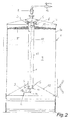
- the rotatable about the axis of rotation 1a nozzle part 3 is formed substantially as a plate nozzle, as seen from Fig. 2 is recognizable.
- the cover part 5 divides the inner space 1b of the container 1 into a first space 9 filled with grape juice and mash and a substantially gas-filled second space 10.
- a connecting channel 11 is provided, which is filled with liquid Area of the first space 9 goes out and which opens above the cover 5 in the second space 10.
- the connecting channel 11 can be arranged concentrically to the axis of rotation 1 a and concentric with the feed line 4 and be formed by a pipe 13 surrounding the feed line 4.
- At least one inlet opening 11a of the connecting channel 11 is located in the lower half, preferably in the lower third of the container 1. It is particularly advantageous if the inlet opening 11a in the region of the nozzle member 3 holding rotary arm 3a of the device 1 and thus in the region of inclined formed container bottom 12 is located. This ensures that even with small quantities and correspondingly deeply arranged cover 5, a pressure equalization between the first space 9 and the second space 10 and a moistening of the pomace from above takes place.
- the first room 9 is filled with grape juice and mash.
- the cover 5 is fixed on the fixing device 6 in a certain height in the container 1. Due to the incipient fermentation and the sealing pomace cake arises in the first space 9, an overpressure, whereby the grape juice is pressed according to the arrows S via the connecting channel 11 in the second space 10.
- the holding forces for the fixing device 6 of the cover 5 can be kept relatively small.
- a moistening of the cover 5 formed by a sieve bottom is effected, whereby drying of the pulp cake is prevented. Unwanted oxidation phenomena in red wine can thus be easily avoided.
Abstract
Description
Die Erfindung betrifft einen Behälter, insbesondere Maischegärtank für die Rotweinherstellung, wobei im Behälter ein Abdeckteil zur Abdeckung eines flüssigen oder zähflüssigen Mediums angeordnet ist, welcher Abdeckteil den Behälter in einen das Medium beinhaltenden ersten Raum und einen darüber angeordneten zweiten Raum teilt, wobei der erste Raum und der zweite Raum über zumindest einen Verbindungskanal miteinander strömungsverbunden sind, wobei der Verbindungskanal von einem flüssigkeitsgefüllten Bereich des ersten Raumes ausgeht.The invention relates to a container, in particular mash fermentation tank for red wine production, wherein in the container a cover for covering a liquid or viscous medium is arranged, which cover part divides the container into a first space containing the medium and a second space arranged above, wherein the first space and the second space are fluidly connected to each other via at least one connection channel, the connection channel starting from a liquid-filled region of the first space.
Bei der klassischen Methode der Rotweingewinnung wird die Maische in Großbehälter gebracht und dort vergoren. Während der Gärung treiben die Kohlensäurebläschen die in der Maische enthaltenen Tresterbestandteile an die Oberfläche und bilden den sogenannten Tresterhut, der von Hand aus oder mittels Rührwerk mehrmals täglich untergetaucht wird. Mitunter sind in den Großbehältern Siebböden eingebaut, um den Maischeauftrieb zu verhindern und eine unerwünschte Oxidation oder einen sogenannten Essigstich der Maische zu verhindern. Unterhalb des ungebrochenen Tresterhutes können allerdings durch den Gärungsprozess hohe Gaskräfte entstehen, welche die Siebbodenhalterungen bzw. den Deckel des Behälters stark belasten oder sogar zerstören können.In the classic method of red wine extraction, the mash is placed in large containers and fermented there. During fermentation, the carbon dioxide bubbles drive the pesticide components contained in the mash to the surface and form the so-called pomace, which is submerged by hand or by means of a stirrer several times a day. Sometimes sieve trays are installed in the large containers to prevent mash buoyancy and to prevent unwanted oxidation or so-called vinegar sting of the mash. Below the unbroken pomace, however, high gas forces can be produced by the fermentation process, which can heavily load or even destroy the sieve bottom holders or the lid of the container.
Die
Die
Die
Weiters offenbart die
Aus der
Die
Ein weiterer Weinbehälter mit einer Trennwand, welche den Behälter in zwei Kammern teilt, ist aus der
Es ist die Aufgabe der Erfindung, diese Nachteile zu vermeiden und mit möglichst geringem Aufwand eine gute Durchmischung zu erreichen und dabei eine unerwünschte Oxidation des sich im Behälter befindenden Mediums zu vermeiden.It is the object of the invention to avoid these disadvantages and to achieve a good thorough mixing with the least possible outlay while avoiding unwanted oxidation of the medium in the container.
Erfindungsgemäß wird dies dadurch erreicht, dass im Behälter eine Vorrichtung zum Mischen des Mediums mit zumindest einer zu mindestens einem Düsenteil führenden Zuführleitung für ein Gas angeordnet ist, wobei der Düsenteil um eine Drehachse drehbar ausgebildet ist, und wobei der Verbindungskanal konzentrisch zur Drehachse des Düsenteils angeordnet ist.According to the invention this is achieved in that in the container, a device for mixing the medium is arranged with at least one leading to at least one nozzle part supply line for a gas, wherein the nozzle part to a Rotary axis is rotatable, and wherein the connecting channel is arranged concentrically to the axis of rotation of the nozzle part.
Der Verbindungskanal kann von der unteren Hälfte, vorzugsweise vom unteren Drittel des Innenraumes des Behälters ausgehen.The connecting channel can emanate from the lower half, preferably from the lower third of the interior of the container.
In einer besonders kompakten und einfachen Ausführungsvariante der Erfindung ist vorgesehen, dass der Verbindungskanal konzentrisch zur Zuführleitung des Düsenteils angeordnet ist, wobei vorzugsweise die Zuführleitung innerhalb des durch ein Rohr gebildeten Verbindungskanals angeordnet ist. Verbindungskanal und Zuführleitung können dabei durch den selben Bauteil gebildet sein.In a particularly compact and simple embodiment of the invention it is provided that the connecting channel is arranged concentrically to the feed line of the nozzle part, wherein preferably the feed line is arranged within the connecting channel formed by a pipe. Connecting channel and supply line can be formed by the same component.
Der Verbindungskanal zwischen dem ersten und dem zweiten Raum bewirkt einen Druckausgleich, wodurch der Abdeckteil, sowie dessen Haltemittel nur wenig beansprucht wird.The connecting channel between the first and the second space causes a pressure equalization, whereby the cover, and its retaining means is only slightly stressed.
Wesentlich ist dabei, dass der Verbindungskanal von einem flüssigkeitsgefüllten Bereich weit unterhalb des Maischehutes ausgeht. Der entstehende Gasdruck im ersten Raum bewirkt, dass über den Verbindungskanal Flüssigkeit in den zweiten Raum oberhalb des Abdeckteiles gedrückt wird, wodurch einerseits ein weitgehender Druckausgleich zwischen dem ersten und dem zweiten Raum erreicht und andererseits ein Austrocknen des Tresterkuchens verhindert wird.It is essential that the connecting channel emanates from a liquid-filled area far below the mash. The resulting gas pressure in the first space causes liquid to be forced into the second space above the cover part via the connection channel, which on the one hand achieves extensive pressure equalization between the first and the second space and, on the other hand, prevents drying of the wort cake.
Zumindest eine Eintrittsöffnung in den Verbindungskanal kann sich dabei im Bereich eines den Düsenteil tragenden Dreharms befinden. Der Austritt aus dem Verbindungskanal ist in jedem Fall oberhalb des Abdeckteils angeordnet, welcher beispielsweise durch ein metallisches Siebblech gebildet sein kann.At least one inlet opening in the connecting channel can be located in the region of a rotary arm carrying the nozzle part. The outlet from the connecting channel is arranged in any case above the cover, which may be formed for example by a metallic screen plate.
Um verschiedene Füllhöhen im Behälter ohne Beeinträchtigung der Qualität des Rotweines zu ermöglichen, ist vorzugsweise vorgesehen, dass der Abdeckteil höhenverstellbar ausgebildet ist, wobei der Abdeckteil in zumindest einer gewählten Höhenposition fixierbar ist.In order to enable different fill levels in the container without affecting the quality of the red wine, it is preferably provided that the cover is formed height adjustable, wherein the cover is fixable in at least one selected height position.
Die Erfindung wird im Folgenden anhand der Figuren näher erläutert. Es zeigen:
- Fig. 1
- einen erfindungsgemäßen Behälter in einer Draufsicht; und
- Fig. 2
- den erfindungsgemäßen Behälter in einem schnittgemäß der Linie II - II in
Fig. 1 .
- Fig. 1
- a container according to the invention in a plan view; and
- Fig. 2
- the container according to the invention in a section along the line II - II in
Fig. 1 ,
In einem Behälter 1 zur Rotweinherstellung ist eine Vorrichtung 2 zum Mischen von Traubensaft und Maische angeordnet. Die Vorrichtung 2 besteht aus mindestens einem Düsenteil 3, welcher starr mit einer Zuführleitung 4 verbunden ist. Düsenteil 3 und Zuführleitung 4 sind drehbar im Behälter 1 angeordnet. Die Zuführleitung 4 ist durch den Behälterdeckel 7 des Behälters 1 geführt und tritt im Bereich einer drehbaren Kupplung 8 in den Behälterdeckel 7 ein. Die Verdrehung der Vorrichtung 2 erfolgt über einen nicht weiter dargestellten Motor. Zur Steuerung der zugeführten Gasmenge ist ein Steuerventil 14 vorgesehen, welches über eine nicht weiter dargestellte Steuereinheit gesteuert werden kann. Mit der Steuereinheit kann auch die Verdreheinrichtung für die Düsenteile 3 verbunden sein.In a
Der um die Drehachse 1a drehbare Düsenteil 3 ist im wesentlichen als Tellerdüse ausgebildet, wie aus
Im Behälter 1 ist ein durch einen Siebboden beispielsweise aus Stahlblech gebildeter höhenverstellbarer Abdeckteil 5 angeordnet, dessen Höhe im Behälter 1 über eine Fixiereinrichtung 6 verstellt werden kann. Der Abdeckteil 5 teilt den Innenraum 1b des Behälters 1 in einen mit Traubensaft und Maische gefüllten ersten Raum 9 und einen im Wesentlichen gasgefüllten zweiten Raum 10. Zur Strömungsverbindung des ersten Raumes 9 und des zweiten Raumes 10 ist ein Verbindungskanal 11 vorgesehen, welcher von einem flüssigkeitsgefüllten Bereich des ersten Raumes 9 ausgeht und welcher oberhalb des Abdeckteiles 5 in den zweiten Raum 10 einmündet. Der Verbindungskanal 11 kann dabei konzentrisch zur Drehachse 1a und konzentrisch zur Zuführleitung 4 angeordnet sein und durch ein die Zuführleitung 4 umgebendes Rohr 13 gebildet sein. Zumindest eine Eintrittsöffnung 11a des Verbindungskanals 11 befindet sich dabei in der unteren Hälfte, vorzugsweise im unterem Drittel des Behälters 1. Besonders vorteilhaft ist es, wenn sich die Eintrittsöffnung 11a im Bereich des den Düsenteil 3 haltenden Dreharms 3a der Vorrichtung 1 und somit im Bereich des geneigt ausgebildeten Behälterbodens 12 befindet. Dadurch ist gewährleistet, dass auch bei geringen Füllmengen und entsprechend tief angeordnetem Abdeckteil 5 ein Druckausgleich zwischen dem ersten Raum 9 und dem zweiten Raum 10 und eine Befeuchtung des Tresterhutes von oben stattfindet.In the
Im Betrieb ist der erste Raum 9 mit Traubensaft und mit Maische gefüllt. Der Abdeckteil 5 ist über die Fixiereinrichtung 6 in einer bestimmter Höhe im Behälter 1 fixiert. Durch die einsetzende Gärung und den abdichtenden Tresterkuchen entsteht im ersten Raum 9 ein Überdruck, wodurch der Traubensaft entsprechend den Pfeilen S über den Verbindungskanal 11 in den zweiten Raum 10 gedrückt wird. Durch diesen Druckausgleich zwischen dem ersten Raum 9 und dem zweiten Raum 10 können die Haltekräfte für die Fixiereinrichtung 6 des Abdeckteiles 5 relativ klein gehalten werden. Zusätzlich wird eine Befeuchtung des durch einen Siebboden gebildeten Abdeckteiles 5 bewirkt, wodurch ein Austrocknen des Tresterkuchens verhindert wird. Unerwünschte Oxidationserscheinungen im Rotwein können somit auf einfache Weise vermieden werden.In operation, the first room 9 is filled with grape juice and mash. The cover 5 is fixed on the fixing device 6 in a certain height in the
Claims (8)
Applications Claiming Priority (1)
| Application Number | Priority Date | Filing Date | Title |
|---|---|---|---|
| AT0149109A AT508866A1 (en) | 2009-09-22 | 2009-09-22 | CONTAINERS, IN PARTICULAR MACHINE TANK FOR RED WINE PRODUCTION |
Publications (1)
| Publication Number | Publication Date |
|---|---|
| EP2308590A1 true EP2308590A1 (en) | 2011-04-13 |
Family
ID=42937853
Family Applications (1)
| Application Number | Title | Priority Date | Filing Date |
|---|---|---|---|
| EP10177320A Withdrawn EP2308590A1 (en) | 2009-09-22 | 2010-09-17 | Container, in particular mash fermentation tank for the production of red wine |
Country Status (2)
| Country | Link |
|---|---|
| EP (1) | EP2308590A1 (en) |
| AT (1) | AT508866A1 (en) |
Families Citing this family (1)
| Publication number | Priority date | Publication date | Assignee | Title |
|---|---|---|---|---|
| CN114160085B (en) * | 2021-12-16 | 2023-06-30 | 山东亚邦化工科技有限公司 | Potassium acetyl sulfoamide apparatus for producing |
Citations (6)
| Publication number | Priority date | Publication date | Assignee | Title |
|---|---|---|---|---|
| FR2497500A1 (en) * | 1981-01-06 | 1982-07-09 | Eta Sa | Wine fermenting vessel with integral header tank for recycled must - has heater fitted between base of head or tank and vessel head-space |
| US4969391A (en) | 1988-04-19 | 1990-11-13 | Societe Atlantique de Techniques Advancees | Wine-making vat |
| DE19517937A1 (en) | 1995-05-18 | 1996-11-21 | Klaus Troxler | Wine fermentation tank with sub-surface sieve force-submerging organic solids |
| AT5698U1 (en) | 2001-11-23 | 2002-10-25 | Hermann Boeck | DEVICE AND METHOD FOR MIXING LIQUID, TEMPERATURE AND / OR GIANT MEDIA |
| DE69909182T2 (en) | 1998-04-20 | 2004-05-06 | Cmb S.N.C. Di Cassi Angelo & C. | Device for wine making |
| FR2892728A1 (en) * | 2005-10-27 | 2007-05-04 | Patrick Lejeune | Processing of wort in a fermentation tank of wine storehouse, comprises introducing vintage into a lower enclosure of the tank, and reassembling and diffusing part of accumulated juice by introducing external gas into the lower enclosure |
-
2009
- 2009-09-22 AT AT0149109A patent/AT508866A1/en not_active Application Discontinuation
-
2010
- 2010-09-17 EP EP10177320A patent/EP2308590A1/en not_active Withdrawn
Patent Citations (8)
| Publication number | Priority date | Publication date | Assignee | Title |
|---|---|---|---|---|
| FR2497500A1 (en) * | 1981-01-06 | 1982-07-09 | Eta Sa | Wine fermenting vessel with integral header tank for recycled must - has heater fitted between base of head or tank and vessel head-space |
| US4969391A (en) | 1988-04-19 | 1990-11-13 | Societe Atlantique de Techniques Advancees | Wine-making vat |
| DE19517937A1 (en) | 1995-05-18 | 1996-11-21 | Klaus Troxler | Wine fermentation tank with sub-surface sieve force-submerging organic solids |
| DE69909182T2 (en) | 1998-04-20 | 2004-05-06 | Cmb S.N.C. Di Cassi Angelo & C. | Device for wine making |
| AT5698U1 (en) | 2001-11-23 | 2002-10-25 | Hermann Boeck | DEVICE AND METHOD FOR MIXING LIQUID, TEMPERATURE AND / OR GIANT MEDIA |
| EP1329254A1 (en) * | 2001-11-23 | 2003-07-23 | Hermann Böck | Device and process for mixing of liquid, viscous and/or pourable media |
| EP1329254B1 (en) | 2001-11-23 | 2005-04-13 | Hermann Böck | Device and process for mixing of liquid, viscous and/or pourable media |
| FR2892728A1 (en) * | 2005-10-27 | 2007-05-04 | Patrick Lejeune | Processing of wort in a fermentation tank of wine storehouse, comprises introducing vintage into a lower enclosure of the tank, and reassembling and diffusing part of accumulated juice by introducing external gas into the lower enclosure |
Also Published As
| Publication number | Publication date |
|---|---|
| AT508866A1 (en) | 2011-04-15 |
Similar Documents
| Publication | Publication Date | Title |
|---|---|---|
| EP1329254B1 (en) | Device and process for mixing of liquid, viscous and/or pourable media | |
| DE3836489A1 (en) | METHOD AND DEVICE FOR FILLING BEVERAGE CAN | |
| EP0155693B1 (en) | Process and apparatus for the treatment of liquid foodstuffs, especially red wine must | |
| DE102009040962A1 (en) | Swirl element, inlet valve, apparatus and method for evaporating or degassing of liquids and their use in brewing processes | |
| AT514863A1 (en) | Process for the production of beer | |
| DE3617519A1 (en) | TWO- OR MULTI-STAGE METHOD FOR REMOVING IMPURITIES FROM STILL OR CARBONIC LIQUIDS, IN PARTICULAR DRINKS, AND APPARATUS FOR CARRYING OUT THIS | |
| DE581432C (en) | Rotary filter under pressure and continuously working | |
| EP2308590A1 (en) | Container, in particular mash fermentation tank for the production of red wine | |
| EP3887495B1 (en) | Brewing device | |
| DE3902620C2 (en) | ||
| EP0946276B1 (en) | Device for bringing solid bodies in the form of pourable pieces into contact with liquids and possibly gases | |
| DE4324157A1 (en) | Method and device for controlling the drainage of wort from a lauter tun | |
| EP0943364A2 (en) | Device for treating a liquid, especially for the purification of water | |
| DE3415699C2 (en) | Method and device for fermenting red wine mash | |
| AT509070B1 (en) | DEVICE AND METHOD FOR FILLING LIQUIDS | |
| EP0337060A1 (en) | Must fermentation tank, more particularly for the fermentation of red wine must | |
| AT14090U1 (en) | Primary fermentation tank with a mechanical cooling and / or degassing | |
| DE1642696A1 (en) | Laeuter device for mash filtering | |
| DE4136491C2 (en) | Method and device for fermenting red wine mash | |
| DE19545080A1 (en) | Pressing vessels against vessel filling machine | |
| EP0655934B1 (en) | Pressure filter | |
| AT219538B (en) | Device for pre-juicing mash, in particular grape mash | |
| DE3924064A1 (en) | Brewing vessel, partic. single or double mash kettles - has tall cooker in relation to contents but allows aeration free heating of fluids | |
| DE3927173C1 (en) | ||
| DE79323C (en) | Refining apparatus |
Legal Events
| Date | Code | Title | Description |
|---|---|---|---|
| PUAI | Public reference made under article 153(3) epc to a published international application that has entered the european phase |
Free format text: ORIGINAL CODE: 0009012 |
|
| AK | Designated contracting states |
Kind code of ref document: A1 Designated state(s): AL AT BE BG CH CY CZ DE DK EE ES FI FR GB GR HR HU IE IS IT LI LT LU LV MC MK MT NL NO PL PT RO SE SI SK SM TR |
|
| AX | Request for extension of the european patent |
Extension state: BA ME RS |
|
| STAA | Information on the status of an ep patent application or granted ep patent |
Free format text: STATUS: THE APPLICATION IS DEEMED TO BE WITHDRAWN |
|
| 18D | Application deemed to be withdrawn |
Effective date: 20111014 |