EP2308341A2 - Behälter mit Werkzeughalterung, Behälter mit einem kosmetischen Werkzeug und zugehöriges kosmetisches Werkzeug - Google Patents
Behälter mit Werkzeughalterung, Behälter mit einem kosmetischen Werkzeug und zugehöriges kosmetisches Werkzeug Download PDFInfo
- Publication number
- EP2308341A2 EP2308341A2 EP10183741A EP10183741A EP2308341A2 EP 2308341 A2 EP2308341 A2 EP 2308341A2 EP 10183741 A EP10183741 A EP 10183741A EP 10183741 A EP10183741 A EP 10183741A EP 2308341 A2 EP2308341 A2 EP 2308341A2
- Authority
- EP
- European Patent Office
- Prior art keywords
- tool
- container
- cosmetic
- housing
- aperture
- Prior art date
- Legal status (The legal status is an assumption and is not a legal conclusion. Google has not performed a legal analysis and makes no representation as to the accuracy of the status listed.)
- Withdrawn
Links
Images






Classifications
-
- A—HUMAN NECESSITIES
- A45—HAND OR TRAVELLING ARTICLES
- A45D—HAIRDRESSING OR SHAVING EQUIPMENT; EQUIPMENT FOR COSMETICS OR COSMETIC TREATMENTS, e.g. FOR MANICURING OR PEDICURING
- A45D34/00—Containers or accessories specially adapted for handling liquid toiletry or cosmetic substances, e.g. perfumes
- A45D34/04—Appliances specially adapted for applying liquid, e.g. using roller or ball
-
- B—PERFORMING OPERATIONS; TRANSPORTING
- B65—CONVEYING; PACKING; STORING; HANDLING THIN OR FILAMENTARY MATERIAL
- B65D—CONTAINERS FOR STORAGE OR TRANSPORT OF ARTICLES OR MATERIALS, e.g. BAGS, BARRELS, BOTTLES, BOXES, CANS, CARTONS, CRATES, DRUMS, JARS, TANKS, HOPPERS, FORWARDING CONTAINERS; ACCESSORIES, CLOSURES, OR FITTINGS THEREFOR; PACKAGING ELEMENTS; PACKAGES
- B65D23/00—Details of bottles or jars not otherwise provided for
- B65D23/12—Means for the attachment of smaller articles
-
- A—HUMAN NECESSITIES
- A45—HAND OR TRAVELLING ARTICLES
- A45D—HAIRDRESSING OR SHAVING EQUIPMENT; EQUIPMENT FOR COSMETICS OR COSMETIC TREATMENTS, e.g. FOR MANICURING OR PEDICURING
- A45D2200/00—Details not otherwise provided for in A45D
- A45D2200/10—Details of applicators
- A45D2200/1009—Applicators comprising a pad, tissue, sponge, or the like
- A45D2200/1018—Applicators comprising a pad, tissue, sponge, or the like comprising a pad, i.e. a cushion-like mass of soft material, with or without gripping means
Definitions
- the present invention relates generally to packaging.
- the present invention concerns a container having a tool retainer incorporated therein.
- the container can contain a cosmetic product.
- cosmetic product in particular a product as defined in Council Directive 93/35/EEC of 14 June 1993.
- Containers often require the application of the contents to a substrate.
- cleansers and cosmetics require the application of the product to the skin.
- the method of application or treatment can be as efficacious as the contents themselves.
- Such methods often involve the use of a separate tool that is not easily stored or transported with the container.
- a container having a tool retainer for accommodating a tool.
- a reusable tool is provided that is configured to rest in the tool retainer.
- US 5,558,453 describes a container that has a hollow envelope defining a chamber for soap and a brush carried by a support that snaps onto the hollow envelope.
- the brush is more flexible than the hollow envelope.
- the brush support snaps into housings formed in the hollow envelope. This attachment of the cosmetic tool to the hollow envelope is robust. The cosmetic tool is therefore held firmly to the hollow envelope defining the chamber, notably during its transport or storage.
- the container is made bulky by the attachment of the tool to the hollow envelope.
- GB 2 392 898 , FR 2 066 293 , US 2005/0067414 , and EP 0 288 347 describe other containers that are not designed to receive a cosmetic product.
- Another object of the invention is to provide a container of this kind that is as compact as possible.
- a container in one embodiment, includes a housing having a first wall and a second wall remote therefrom, a depth d associated with a distance between the first and second walls, and an aperture in the housing configured to retain a tool, wherein the aperture extends between the first and second walls and has a varying size along the depth d.
- the container can further comprise a means for removably fastening the tool to the aperture.
- Said means for removably fastening the tool to the aperture can comprise a pressure fit or a snap fit.
- the aperture can have a first wall recession adjacent the first wall.
- the aperture can have a second recession adjacent the second wall.
- the aperture can have an opening connecting the first and second wall recessions.
- the tool can be entirely contained between the first and second walls, or a portion of the tool can protrudes from outside a first and/or second wall.
- the aperture can have a varying shape along depth d.
- a container system in another embodiment, includes a tool that includes a first end, and a second end remote therefrom, and a container that includes a housing having a first wall and a second wall remote therefrom, a depth d associated with a distance between the first and second walls, and an aperture in the housing configured to retain a tool, wherein the aperture extends between the first and second walls and has a varying size along the depth d.
- the aperture can have a first wall recession adjacent the first wall.
- the aperture can have a second recession adjacent the second wall.
- the tool can be entirely contained between the first and second walls.
- the tool can have a spool-like shape.
- the second end of the tool can have a means for releasably fastening to a substrate.
- the means for releasably fastening to the substrate can be a hook, a suction cup, or a string.
- a container in still another embodiment, includes a housing having a first wall and a second wall remote therefrom, and a recession at the first wall, extending toward the second wall, at a depth d, configured to retain a tool, wherein a size of the recession varies along the depth d.
- the tool can entirely lye within the container.
- the recession can include a flange for retaining the tool.
- the recession can permit the tool to be snap fitted.
- a container having a tool retainer for accommodating a tool. Further, a reusable tool is provided that is configured to rest in the tool retainer.
- a container system in yet another embodiment, includes a tool that includes a first end, and a second end remote therefrom, and a container that includes a housing having a first wall and a second wall remote therefrom, a depth d associated with a distance between the first and second walls, and an aperture in the housing configured to retain a tool, wherein the aperture extends between the first and second walls and has a varying size along the depth d.
- a container in still another embodiment, includes a housing having a first wall and a second wall remote therefrom, and a recession at the first wall, extending toward the second wall, at a depth d, configured to retain a tool, wherein a size of the recession varies along the depth d.
- a “cosmetic tool” is in particular a cosmetic product applicator having an active part designed to come into contact with a body surface of a user in order to apply cosmetic product to this surface.
- a cosmetic tool may for example be a cosmetic treatment tool such as a nail file or a massage roller, or a tool for assisting in the application of a cosmetic product, such as a mirror.
- the hollow envelope comprises, in the receiving housing, retention means for retaining the cosmetic tool, the whole of the cosmetic tool being received in the receiving housing without projecting outside of the receiving housing beyond the hollow envelope when the cosmetic tool is engaged in the retention means.
- the container(s) according to the above embodiment of the invention may have one or more of the following features, singly or in any technically possible combination:
- the invention further relates to a cosmetic tool of the type comprising:
- the cosmetic tool is advantageously suitable for reception in a container as defined above.
- the tool may have one or more of the features defined above.
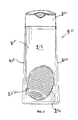
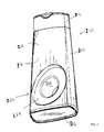
- a container system 210 is presented, with reference to Figs. 1 - 3 .
- a container 212 is shown having a dispenser end 214 and a closed end 216. Further, the container 212 includes a front wall 218 and a rear wall 220 remote therefrom. Connecting the front wall 218 and the rear wall 220 are two side walls 222.
- the front wall 218, rear wall 220 and side walls 220 may be formed integrally in one step.
- the container walls may be formed separately and then be fastened together, either removably or separately.
- the container may be formed of any suitable materials, but preferably a thermoplastic material.
- the container 212 includes a tool retainer 224.
- the tool retainer 224 can be a cavity or depression formed at either the front or rear walls 218, 220, respectively.
- the tool retainer 224 can be an aperture going entirely through the container's depth, from the front wall 218 to the rear wall 220.
- the aperture or recession is formed to conform to the shape of the tool to be inserted and retained in the container system 210.
- the specific configuration of the retainer 224 will mirror the dimensions and specific configuration of the tool. Accordingly, various alterations and dimensions are possible for both the tool and the tool retainer 224, without deviating from the spirit and scope of the present invention.
- a tool 226 as shown in Figs. 8-9 has a general shape of a spool.
- the tool 226 has a first end 228, a second end 230 remote therefrom, and a stem 232 connecting the first and second ends, 228, 230.
- the first end 228 can include an abrasive surface.
- Such an abrasive surface can be in the form of bristles, nubs, and the like.
- the abrasive surface is the surface a user would employ to clean the skin or apply the contents of the container.
- the tool 226 can be any type of applicator, scrubber or the like.
- the surface of the first end 228 can contain no features and be smooth, depending on the function to be served. For example, if the tool is to serve only the purpose of applying the contents to a substrate, it may be desirable to include no abrasive surface on the first end 228.
- the second end 230 can serve as a handle or gripper means for the user.
- the second end 230 contains a suction cup feature.
- the suction cup feature enables the tool 226 to be used in a shower or bathroom. It is contemplated that a user can apply, or treat the skin or desirable surface and then attach the tool 226 to the wall of the shower or bathroom mirror using the suction cup feature, or any appropriate surface.
- the second end 230 need not incorporate the suction cup feature. Rather, the second end 230 can incorporate a number of other features facilitating ease and convenience for the consumer.
- the second end can include a means for removably fastening to a shower caddy. A hook, a hole for attaching the tool 226 to a string, or any like feature can be incorporated.
- the stem 232 can be any length as desired. Further the stem 232 can be formed integrally with the first and second ends 228, 230 respectively, or be formed separately therefrom and then coupled thereto. Lastly, the stem 232 need not be present. For example the second end 230 may simply be formed on a back end of the first end 228.
- first end 228 is shown having an oval shape, with a uniform thickness, any variety of shapes, sizes, thicknesses or configurations may be employed. Similar variations can be utilized for the second end 230 as well.
- the stem 232 can have a generally cylindrical configuration with a constant radius or a varying radius. The shape of the stem 232 can also be non-cylindrical.
- a first end, a second end and a stem are illustrated and described.
- the tool 226 need not be limited to a circular shape or oval shape.
- the shape of the tool 226 can be varied and modified as previously discussed.
- the tool 226 can be elongated and have a peanut shape so that one side of the tool can serve as a handle. Numerous possibilities exist for the shape, configuration, features and final look of the tool 226.
- the images of the tool 226 in Figs. 8-10 are included for illustrative purposes for a preferred embodiment and to discuss the corresponding features of the tool retainer 224 of the container 212.
- the container 212 generally has an aperture that serves as a tool retainer 224.
- the tool retainer 224 is advantageous for a number of reasons. First, it is a simple matter to include an applicator tool or scrubber tool with the container. Further, this serves as an advantage for the manufacturer because it facilitates easy of packaging in providing the consumer two products in one. Transporting the products is also easily facilitated. The retailer also benefits in that they do not need to provide added shelf space and can provide two products in the space required for one.
- the consumer has numerous benefits. First, the consumer need only purchase one unit and obtains an applicator or scrubber tool when purchasing the cleanser. Second, the type of tool appropriate for the purpose can be configured specifically for the container. This eliminates the customer having to research and decide what tool is appropriate. Further, the consumer can store the tool by placing it in the tool retainer 224, unlike packages of towelettes, washcloths or brushes. Next, the consumer can easily transport the cleanser and tool in one simple and easy system. Using a thermoplastic material for the tool 226 keeps the consumer from having to wait for the tool to dry, unlike with reusable wash cloths. The suction cup feature provides an added benefit in that the consumer can use the tool in the shower and easily store it in the shower by adhering the tool to the shower walls. The consumer can similarly use the tool at the sink to wash his or face and adhere the tool to the mirror. The tool is also reusable, ecologically friendly and does not require costly batteries. Further, use of the appropriate material can reduce or eliminate concerns of bacteriological growth.
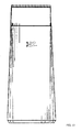
- the tool 226 has a spool-like shape. Therefore, the tool retainer 224 is configured to accommodate the shape of the tool 226 and also has a similar spool-like shape. Accordingly, as shown in Figs. 4-7 , the tool retainer 224 has a front wall recess 234 disposed at the front wall 218.
- the front wall recess 234 serves as a seat for the first end 228 of the tool 226.
- the front wall recess 234 can be any depth as desired.
- the front wall recess 234 has a depth A that allows for the first end 228 of the tool 226 to be retained entirely therewith.
- the first end 228 of the tool 226 has a thickness a, as shown in Fig. 9 .
- Depth A can be at least as large as thickness a to prevent the tool 226 from protruding out of the tool retainer 224.
- the first end 228 of the tool 226 can be flush with the front wall 218 of the container.
- the tool retainer 224 can have an aperture 236 to accommodate the stem 232 of the tool 226.
- the aperture 236 is formed in the container 212 and exposes a generally cylindrical inner wall 238 of the container 212.
- the aperture 236 has a length B ( Fig. 7 ) and shape corresponding to the length b and shape of the stem 232 ( Fig. 9 ).
- the tool retainer 224 can contain a rear wall recess 244, as shown in Figs. 6-7 .
- the rear wall recess 244 is similar to the front wall recess 234.
- the rear wall recess 244 is disposed at the rear wall 220 and is a recess formed therein.
- the rear wall recess 244 can be sized and shaped to accommodate the second end 230 of the tool 226.
- the size and shape can vary according to the size and shape of the second end 230 of the tool 226.
- the depth can vary depending on the desire to keep the second end 230 flush with the rear wall 220 as previously discussed.
- a depth C ( Fig. 7 ) of the rear wall recess 244 can be greater than the thickness of the second end c ( Fig. 9 ).
- a front wall recess 234, a rear wall recess 244 and an inner wall 238 are illustrated and described.
- any number of recesses and inner walls are conceivable and consistent with the scope of this invention.
- the tool retainer 224 mirrors the shape and configuration of the tool 226.
- the tool retainer 224 can contain various methods of removably fastening the tool 226 to the container 212.
- the inner wall 238 can include a lip or flange 240 ( Fig. 7 ) to retain the stem 232.
- the stem 232 is snap-fitted into the inner wall 238 of the tool retainer 224.
- a flange 240 can be annular or be periodic. If the flange 240 is periodic, the fastening means will resemble tabs placed at the inner wall 238. Thus the stem 232 can be snap fitted into such tabs.
- the inner wall 238 can alternatively contain threads for threadably fastening the tool 226 to the tool retainer 224.
- the stem 232 can also contain a corresponding fastening means such as, tabs, an annular ring, ridges or threads 242 to facilitate fastening to the tool retainer 224.
- a corresponding fastening means such as, tabs, an annular ring, ridges or threads 242 to facilitate fastening to the tool retainer 224.
- the inner wall 238 and/or the tool 226 be configured with means for removably fastening the tool 226.
- the inner wall 238 has a portion of reduced size. This reduced size allows the stem 232 to stay in place, when inserted into the tool retainer 224.
- the tool retainer 224 can be configured without having an aperture extending through the entire container, as will be discussed hereinafter, such a configuration has an added advantage.
- having the rear wall recess 234 permits the user to press on the second end 230 of the tool 226 at the rear wall recess 234 and drive it forward through the front wall recess 234 and out of the container 212.
- the ability to keep the tool 226 retained entirely within the walls of the container 212 is advantages from a shipping and convenience standpoint.
- tabs may be formed either on the container 212 or the tool 226 to facilitate ease of removal.
- the tool 226 can also be retained in the container 212 such that a portion of the tool 226 does protrude out from the walls of the container 212 to facilitate the removal of the tool 226.
- the fastening means can be placed anywhere in the tool retainer 224 and need not be placed solely at the inner wall 228.
- the fastening means can be placed in the front wall recess, the rear wall recess, or a combination of some or all of these locations.
- the fastening means can be placed anywhere along the body of the tool 226.
- the material used in forming the tool 226 should be flexible and pliable enough to accommodate insertion into the tool retainer 224, particularly the inner wall 238.
- the material should be rigid and strong enough to allow the inner wall 238 or the removable fastening means to retain the tool 226 within the tool retainer 224.
- a tool 246, as shown in Fig. 10 resembles a flat disk or pancake shape.
- Such an alternate tool 246 can have any shape, size or configuration as desired.
- an alternate tool retainer 248 includes a shallow recession or nest 250 as shown in Figs. 11-14 .
- a nest 250 can also be shaped and dimensioned according to the shape and dimensions of the alternate tool 246.
- the nest 250 can include a first nest recess 252 to accommodate the tool 246. Additional recesses can be formed according to the size and shape of the alternate tool 246.
- the nest 250 has a depth of less than a thickness of the container 212, as measured by the distance between the first and second walls 218, 220, respectively.
- Fastening means to removably secure the tool 246 to the nest 250 can be employed in a manner similar to that disclosed earlier.
- the fastening means can comprise threads, an annular lip, tabs or the like.
- Such fastening means can be disposed at the first nest recess 252 or any where along the inner wall of the nest 250.
- a portion of the nest 250 can have a reduced size to retain the alternate tool 246, as discussed previously. If the tool 246 is retained entirely within the container 212, such that the tool 246 is flush with the walls of the container 212, a means for removing the tool 246 from the container 212 may be employed.
- the tool 46 may be configured to protrude outside of the walls of the container 212 so as to facilitate removal.
- the tool retainer 224 can be placed anywhere on the container.
- the tool retainer 224 can be placed at the closed end 216 and be recessed within the closed end 216.
- the tool retainer 224 can be placed at the top of the container 212 near the dispenser end 214.
- the tool retainer 224 can be incorporated into the dispenser itself.
- the tool retainer 224 can serve as a cap for the dispenser or be configured such that the tool itself can be used to as a plug to close the dispenser end 214.
- the lid used to seal and unseal the container can include a nest or recession to accommodate the tool within the lid confines.
- the tool retainer need not be on the container body.
- many different variations can be employed in incorporating a tool retainer in a container.
- front and rear are used in a relative way with reference to the Figures 1 a to 9a.
- the term “front” usually means nearer to the user, while the term “rear” usually means further away from the user.
- a first container 10 is intended to contain a cosmetic product 12 with a view to its application to a body surface of a user.
- the cosmetic product 12 is advantageously a liquid, a cream, a gel, or potentially a fluidized solid such as a powder.
- the cosmetic product may for example be a shampoo, a soap or a foaming cream.
- the first container 10 comprises a hollow envelope 14 containing the cosmetic product 12, a cosmetic product dispensing head 16 mounted on one end of the hollow envelope 14, and a cosmetic tool 18 carried by the hollow envelope 14.
- the container 10 also comprises, prior to its first use, a film 20 to protect the cosmetic tool 18.
- the hollow envelope 14 generally extends along a long axis A-A' which is shown as vertical in Figure 4a .
- the hollow envelope 14 defines internally a chamber 22 of cosmetic product and externally a housing 24 for receiving the cosmetic article 18 as a tool retainer.
- the hollow envelope 14 comprises an upper part 25A which is basically axisymmetric about an axis B-B' perpendicular to the axis A-A', and a lower part 25B whose greatest width, measured at right angles to the axis A-A', is less than the greatest width of the upper part 25A.
- the upper part 25A defines the receiving housing 24 and the lower part 25B carries the head 16.
- the hollow envelope 14 is a single moulded part. It may for example be based on a polyolefin such as polypropylene, polyethylene or a PET-type polyester.
- the elastic modulus of the material of the hollow envelope 14 is between 60 MPa and 1500 MPa, preferably between 800 MPa and 1500 MPa. As will be seen later, the envelope 14 is thus significantly more rigid than the cosmetic tool 18.
- the hollow envelope 14 comprises a front wall 26, a rear wall 28, visible in Figure 3a , and an outer peripheral wall 30 connecting the front wall 26 to the rear wall 28.
- the hollow envelope 14 also comprises an inner peripheral wall 32 defining the housing 24 and an end wall 34 on which the dispensing head 16 is mounted.
- the front wall 26 has a basically planar main region 36 situated around the through-housing 24 and extending axially towards the lower part 25B of the hollow envelope 14.
- the planar region forms a supporting surface for the protective film 20.
- the rear wall 28 is rounded. It has two concave regions 38 in the upper part 25A of the envelope 14. The concave regions 38 extend parallel to the axis A-A', one on either side of the housing 24. This enables the bottle not to rotate, and to be stable when being filled.
- the outer peripheral wall 30 is roughly a cylinder of axis B-B' in the upper part 25A. It has lateral necked regions 40A, 40B between the upper part 25A and the lower part 25B of the hollow envelope 14. The necked regions 40A, 40B are to facilitate the holding of the hollow envelope 14 between the fingers of a user.
- the end wall 34 extends approximately transversely relative to the axis A-A' of the end of the lower part 25B. It comprises fixing means (not shown) for the head 16 and a cosmetic product dispensing neck defining an opening for the passage of the product (not visible).
- the inner peripheral wall 32 is uninterrupted and is axisymmetric about the axis B-B'.
- This wall comprises, when proceeding along the axis B-B' from the front wall 26 to the rear wall 28, a basically cylindrical front region 50 of axis B-B', a first bearing surface 52 for the cosmetic tool 18, a basically frustoconical intermediate region 54, and a central cylindrical region 56 whose lateral dimension is less than that of the front region 50.
- the inner peripheral wall 32 also includes a second bearing surface 58 for the cosmetic tool 18 and a divergent rear region 60.
- the front region 50 has a maximum transverse dimension, measured at right angles to the axis B-B', greater than that of all the other regions 52 to 60.
- the first bearing surface 52 extends approximately perpendicular to the axis B-B'. It faces out of the housing, towards the front wall 26.
- the transverse dimension of the first bearing surface 52 is relatively small.
- the annular surface defined by the first bearing surface 52 is less than 50% of the greatest cross section of the housing 24, measured level with the front wall 26.
- the radial dimension of the annular surface defined by the first bearing surface 52, measured radially relative to the axis B-B', is less than 30% of the greatest radial dimension of the housing 24, measured level with the front wall.
- the frustoconical intermediate region 54 forms an angle of between 5° and 45° to the axis B-B' when projected onto an axial plane passing through this axis.
- the frustoconical region 54 defines towards the rear a space designed to deform the cosmetic tool 18, and forms a stop for the cosmetic tool 18 when the latter is inserted into the housing 24.
- the frustoconical region 54 faces out of the housing 24 towards the front wall 26. It has a cross-sectional area greater than 30% of the greatest cross-sectional area of the housing 24, projected onto a plane perpendicular to the axis B-B'.
- the central cylindrical region 56 comes closer to the axis B-B' than the front region 50 does. Its transverse dimension is less than that of the other regions, so as to form an annular neck in the housing 24.
- the second bearing surface 58 is formed by an essentially annular shoulder. It faces out of the housing 24 towards the rear wall 28, in the opposite direction to the first bearing surface 52. It defines an annular surface whose dimension is approximately equal to that of the first bearing surface 52.
- the divergent rear region 60 comes out at the rear wall 28. Its transverse cross section increases towards the rear wall 28.
- the greatest transverse dimension defined by the rear region 60 is less than the greatest transverse dimension defined by the front region 50.
- the regions 50 to 60 define towards the axis B-B' the housing 24.
- the housing 24 thus penetrates through the hollow envelope 24 along the axis B-B'. It comprises a front volume 62 whose greatest transverse cross section is in the front region 50 and frustoconical region 54, an intermediate volume 64 whose smallest transverse cross section is in the central cylindrical region 56, and a rear volume 66 of intermediate transverse cross section in the rear region 60.
- the housing 24 comes out through the front volume 62 at the front wall 26 in the form of a cosmetic tool removal opening 68. It comes out at the rear through the rear volume 66 in the rear wall 28 in the form of a secondary opening 70 whose transverse cross section is less than that of the removal opening 68.
- the outline of the receiving housing 24 is closed on any cross section perpendicular to the axis B-B'.
- the first bearing surface 52 and the second bearing surface 58 which face in opposite directions out of the housing 24, form cosmetic tool 18 retention means 72 situated in the housing 24.
- the walls 26 to 34 define internally the chamber 22 which contains the cosmetic product 12.
- the only opening of the chamber 22 is the dispensing opening defined in the end wall 34.
- the dispensing head 16 comprises a peripheral skirt 80 fixed to the lower wall 34, an end plate 82 defining a product dispensing orifice 84, and a removable closing flap 86 capable of being moved between an orifice 84 closing configuration and an orifice 84 opening configuration.
- the chamber 22 opens through the orifice 84 to allow the product 12 contained in the chamber 22 to be dispensed to the exterior, for the purpose of applying it to a body surface of the user.
- the cosmetic tool 18 is received removably in the receiving housing 24 which is defined externally by the hollow envelope 14, through this envelope 14.
- the cosmetic tool 18 is thus movable between a storage position, in which the whole of it is received in the housing 24 and engaged in the retention means 72, and a use position, in which the whole of it is removed from the housing 24 and in which it is movable independently of the hollow envelope 14.
- the cosmetic tool 18 is a cosmetic product applicator forming a brush.
- the cosmetic tool 18 comprises an active part 100 for application of cosmetic product. This part is designed to come into contact with a body surface in order to apply cosmetic product to this surface, and a handle 102 allowing the tool to be held by the user's fingers to allow it to be manipulated.
- the cosmetic tool 18 comprises a sucker 104 mounted on the free end of the handle 102 and a retention member 106 designed to engage with the retention means 72 provided in the housing 24.
- the active part 100 comprises a plate 108 and a plurality of bristles 110 projecting from an outward surface 112 of the plate.
- the outline of the plate 108 is basically homothetic to the external outline of the housing 24 in the front volume 62.
- the plate 108 defines an inward surface 114 on the opposite side to the outward surface 112.
- the inward surface 114 is designed to engage, via a first bearing face 116 situated on the outer edge of the plate 108, with the first bearing surface 52 when the cosmetic tool 18 is engaged in the retention means 72.
- the bristles 110 project out from the lower surface 112, on the opposite side to the handle 102.
- the handle 102 is formed by a neck 118 which projects inwards along an axis C-C' generally perpendicular to the inward surface 114.
- the greatest radial dimension of the handle 102 is less than that of the plate 108 and less than or equal to the smallest radial dimension of the housing 24, measured in the central cylindrical region 56.
- the sucker 104 is on the free end of the handle 102. It has a concave inward cavity 120 with its open side turned away from the plate 108.
- the retention member 106 is formed by a collar 122 projecting radially away from the axis C-C' with respect to the neck 118.
- the transverse dimension of the collar 122 measured perpendicular to the axis C-C', is greater than the smallest transverse dimension of the housing 24, measured perpendicular to the axis B-B' in the central cylindrical region 56.
- the collar 122 has a second bearing face 124 which faces the upward surface 114 of the active part 100 and extends towards the first bearing face 116.
- the second bearing face 124 is designed to engage with the second bearing surface 58, when the cosmetic tool 18 is received in the housing 24 and engaged in the retention means 72.
- the distance d1 between the bearing face 124 of the outer edge 116, measured parallel to the axis C-C', is slightly less, for example between 0.9 times and 0.99 times the distance d2 between the first bearing surface 52 and the second bearing surface 58, measured parallel to the axis B-B'.
- the cosmetic tool 18 when the cosmetic tool 18 is received in the housing 24 and engaged in the retention means 72, the cosmetic tool 18 is held in place under tension between the second bearing face 124 and the first bearing face 114 by the retention means 72.
- the cosmetic tool 18 is more flexible than the hollow envelope 14, so that at least one face 124 of the cosmetic tool 18 engaging with the retention means 72 is deformable when the cosmetic tool 18 is moved from its storage position received in the housing 24 and engaged in the retention means 72, to its removed position outside of the housing 24, without significantly deforming the hollow envelope 14, particularly at the retention means 72.
- the retention member 106 may for example be produced from a material softer than the material forming the hollow envelope 14 at the retention means 72.
- the retention member 106 is thus deformable during the removal of the tool 18 between a radially extended rest position as shown in Figures 2a , 6a and 8a , and deformed positions in which it is radially contracted in the vicinity of the handle 102 as shown in Figures 7a and 9a .
- the cosmetic tool 18 is made in one piece based on a material with a hardness less than that of the material of the envelope 14.
- the material forming the tool 18 may for example have an elastic modulus of less than 400 MPa (e.g. if this material is a polyolefin) and advantageously a hardness of less than 70 Shore A and in particular between 20 Shore A and 50 Shore A.
- This material may for example be a thermoplastic elastomer (TPE) such as SEBS, SBS, Santoprene, or a polyolefin, or be silicone-based.
- TPE thermoplastic elastomer
- SEBS SEBS
- SBS SBS
- Santoprene or a polyolefin
- silicone-based silicone-based
- the plate 108 is also deformable by bending towards the axis C-C' when the cosmetic tool 18 is inserted into the housing 24, as will be described later.
- the protective film 20 is bonded adhesively to the planar region 36 of the front wall 26. It closes off the receiving housing 24 towards the exterior, at least prior to the first use of the container 10.
- the hollow envelope 14 the closing head 16 and the cosmetic tool 18 are made separately and are supplied. At this point the tool 18 is in its removed position, not in the receiving housing 24.
- the collar 122 extends approximately perpendicular to the axis C-C'.
- the cosmetic tool 18 is engaged in the housing 24, by inserting, in succession, the sucker 104, the handle 102 with the retention member 106, and then the active part 100 through the removal opening 68, in a rearward movement along the axis B-B'.
- the central region 56 and the retention means 72 do not deform significantly during the movement of the retention member 106.
- the plate 108 bends towards the axis C-C' in the space 140 available between the inward surface 114 and the frustoconical region 54. Bending of the plate is limited axially rearwardly by the frustoconical region 54.
- the retention member 106 now expands radially away from the axis C-C' so that its greatest transverse dimension is greater than the greatest transverse dimension of the central cylindrical region 56.
- the cosmetic tool 18 is therefore held under slight tension in the housing 24 by means of the retention member 106 and the active part 100.
- the cosmetic tool 18 is now in its storage position, retained in the housing 24. In this position the whole of the tool 18 is contained within the housing 24, without projecting out of the housing 24 beyond the front wall 26 or beyond the rear wall 28.
- the cosmetic tool 18 is retained in a highly reliable and firm manner within the housing 24. This makes it easy to handle when filling the chamber 22 with cosmetic product 12 and/or during the transport and subsequent packaging of the container 10.
- the container 10 takes up little space. This allows it to be mass-produced on a production line without the risk of interference between individual finished containers 10.
- the chamber 22 is filled with cosmetic product 12 and the applicator head 16 is fitted on the end of the hollow envelope 14.
- the adhesive protective film 20 can then be placed on the planar region 36 without interfering with the cosmetic tool 18, which is held securely in the housing 24 without projecting beyond the front wall 26.
- the user withdraws the protective film 20 to reveal the removal opening 68.
- this pressure deforms the retention member 106 radially towards the handle 102 and towards the free end of the handle 102, owing to its contact with the central region 56.
- the retention member 106 then slides off the second bearing surface 58 and slides in the direction of the axis B-B' against the central cylindrical region 56, towards the removal opening 68, until it enters the front volume 62. This movement carries the active part 100 through the removal opening 68 and out of the housing 24.
- the central region 56 and the retention means 72 are not significantly deformed by the passage of the retention member 106.
- the active part 100 can then be grasped by the user to withdraw the tool 18 completely from the housing 24.
- Removal of the cosmetic tool 18 is therefore a very simple, user-friendly action.
- the user opens the closing flap 86 and exposes the dispensing orifice 84 so as to remove some of the cosmetic product 12 from the chamber 22.
- the user may apply it directly to a body surface or to the outward surface 112 of the cosmetic tool 18 between the bristles 110.
- the user may attach the cosmetic tool 18 to a surface, situated for example in the bathroom, by means of the sucker 104.
- the user may insert the tool 18 back into the receiving housing 24 and re-engage it in the retention means 72, as described above.
- the cosmetic tool 18 includes a part that is stiffer than the retention member 106, for example on the handle 102.
- the active part 100 of the cosmetic tool is formed by an applicator fitted with a piece of foam, felt, nonwoven material, or with a sponge, a brush with coaxially mounted bristles, a brush with bristles mounted transversely on a twisted or injection-moulded core, or with a comb, spatula, razor, or roller.
- the active part may also form or include a cosmetic treatment tool such as a scraper, a massage roller, a cuticle pusher or a nail file.
- a cosmetic treatment tool such as a scraper, a massage roller, a cuticle pusher or a nail file.
- the cosmetic tool 18 is not necessarily provided with a sucker 104 on its free end.
- the sucker 104 defines the bearing face 124 on a bearing surface 58 of the retention means 72.
- the housing 24 is a blind housing. Access to the housing 24 and to the cosmetic tool 18 is through the removal opening 18 only.
- the outline of the transverse cross section of the housing 24 is elongated, as for example an oval or an ellipse, or polygonal, such as triangular, square or rectangular.
Landscapes
- Engineering & Computer Science (AREA)
- Mechanical Engineering (AREA)
- Closures For Containers (AREA)
- Details Of Rigid Or Semi-Rigid Containers (AREA)
Applications Claiming Priority (3)
| Application Number | Priority Date | Filing Date | Title |
|---|---|---|---|
| US24704309P | 2009-09-30 | 2009-09-30 | |
| FR0956807A FR2950513B1 (fr) | 2009-09-30 | 2009-09-30 | Recipient portant un accessoire cosmetique, accessoire cosmetique et procede de traitement associes. |
| US25308309P | 2009-10-20 | 2009-10-20 |
Publications (2)
| Publication Number | Publication Date |
|---|---|
| EP2308341A2 true EP2308341A2 (de) | 2011-04-13 |
| EP2308341A3 EP2308341A3 (de) | 2011-05-04 |
Family
ID=42122992
Family Applications (1)
| Application Number | Title | Priority Date | Filing Date |
|---|---|---|---|
| EP10183741A Withdrawn EP2308341A3 (de) | 2009-09-30 | 2010-09-30 | Behälter mit Werkzeughalterung, Behälter mit einem kosmetischen Werkzeug und zugehöriges kosmetisches Werkzeug |
Country Status (3)
| Country | Link |
|---|---|
| US (1) | US8562233B2 (de) |
| EP (1) | EP2308341A3 (de) |
| FR (1) | FR2950513B1 (de) |
Cited By (1)
| Publication number | Priority date | Publication date | Assignee | Title |
|---|---|---|---|---|
| FR3003450A1 (fr) * | 2013-03-25 | 2014-09-26 | Oreal | Palette de reception d'un produit cosmetique, dispositif d'aide a l'application d'un produit cosmetique, necessaire de traitement cosmetique et procede d'application de produit cosmetique associes |
Families Citing this family (12)
| Publication number | Priority date | Publication date | Assignee | Title |
|---|---|---|---|---|
| US9144933B2 (en) * | 2011-01-26 | 2015-09-29 | James D. Gillingwater | Receptacle for attaching to a product having a curved wall |
| FR3010874B1 (fr) * | 2013-09-23 | 2018-02-09 | L'oreal | Accessoire cosmetique comprenant une partie active en styrene elastomerique |
| US9591908B2 (en) * | 2014-04-15 | 2017-03-14 | Aa R&D Llc | Press-type dispensing container |
| US20150359311A1 (en) * | 2014-06-13 | 2015-12-17 | Abeke Akinyinka | Lotion Applicator Device |
| US20160074273A1 (en) * | 2014-09-16 | 2016-03-17 | Rad Innovation LLC | Toolkit for massage and muscle release |
| US10293977B2 (en) * | 2015-05-22 | 2019-05-21 | EVI Spirits | Vodka bottle: pass through logo insert |
| US20190256254A1 (en) * | 2015-05-22 | 2019-08-22 | EVI Spirits LLC | Vodka bottle: pass through logo insert |
| US10092077B1 (en) * | 2017-04-11 | 2018-10-09 | Ojip, Llc | Device for applying and removing nail polish |
| USD1011196S1 (en) * | 2018-11-01 | 2024-01-16 | Outinfutures Co., Ltd. | Cosmetic container |
| US11267615B2 (en) * | 2019-06-20 | 2022-03-08 | Elc Management Llc | Fragrance bottle with diffuser |
| US12257209B2 (en) | 2019-07-11 | 2025-03-25 | Howard Beader | Recycled two cell container device and methods of manufacturing a recycled two cell container device |
| US11259990B2 (en) | 2019-07-11 | 2022-03-01 | Mother Concepts Inc. | Recycled two cell container device and methods of manufacturing a recycled two cell container device |
Citations (7)
| Publication number | Priority date | Publication date | Assignee | Title |
|---|---|---|---|---|
| FR2066293A5 (de) | 1969-10-23 | 1971-08-06 | Roth Gmbh Chemische | |
| EP0288347A1 (de) | 1987-03-25 | 1988-10-26 | THE PROCTER & GAMBLE COMPANY | Verpackung für flüssiges Waschmittel und Verfahren zu ihrer Verwendung |
| US5558453A (en) | 1995-05-18 | 1996-09-24 | Gojo Industries, Inc. | Container and applicator combination |
| GB2392898A (en) | 2002-08-23 | 2004-03-17 | Speedy Act Internat Ltd | Container having a removable subsidiary container |
| US20050067414A1 (en) | 2003-07-28 | 2005-03-31 | Erik Lipson | Multiple cavity container with method and apparatus for forming the same |
| WO2007053632A2 (en) * | 2005-10-31 | 2007-05-10 | James Joseph Osborne | Snap-ring system for connecting separate components |
| US20080138138A1 (en) * | 2005-02-25 | 2008-06-12 | L'oreal | Method Of Applying Makeup By Means Of A Vibrating Applicator |
Family Cites Families (21)
| Publication number | Priority date | Publication date | Assignee | Title |
|---|---|---|---|---|
| US2374092A (en) * | 1942-08-22 | 1945-04-17 | Glaser Michael | Multiple vessel combination |
| US3443710A (en) * | 1967-09-13 | 1969-05-13 | Monsanto Co | Container |
| WO1982000576A1 (en) * | 1980-07-03 | 1982-03-04 | R Patik | Toothbrush container with dispenser |
| US4592478A (en) * | 1984-10-02 | 1986-06-03 | Richard Laconis | Container assembly |
| US4835813A (en) * | 1988-03-18 | 1989-06-06 | Lorenzana Moises B | Protective cover for toothbrush |
| US4881648A (en) * | 1988-09-15 | 1989-11-21 | Hagerty Robert F | Container for tablets, pills or the like |
| DE8813057U1 (de) * | 1988-10-18 | 1988-12-08 | Jonas, Konrad Hans, 40629 Düsseldorf | Behälter mit Zusatzbehältnis |
| US5316398A (en) * | 1993-03-04 | 1994-05-31 | Conros Corporation | Combination bottle and stick |
| US6231258B1 (en) * | 1997-03-19 | 2001-05-15 | Kingsley & Associates, Inc. | Jewelry cleaning apparatus |
| WO1999028201A1 (en) * | 1997-12-01 | 1999-06-10 | Downs Karen J | Bottle |
| US6302608B1 (en) * | 2000-01-19 | 2001-10-16 | Joseph S. Kanfer | Bottle and brush combination |
| US6419123B2 (en) * | 2000-04-19 | 2002-07-16 | Mary Ellen Colquhoun | Liquid soap dispensing container |
| KR200209938Y1 (ko) * | 2000-07-25 | 2001-01-15 | 변영광 | 화장품 용기 |
| USD461596S1 (en) * | 2001-03-21 | 2002-08-13 | Joseph G. Angeletta | Liquid and lotion applicator |
| DE10153689A1 (de) * | 2001-10-31 | 2003-05-15 | Geka Brush Gmbh | Vorrats-und Applikatoreinheit |
| US6722805B1 (en) * | 2002-12-11 | 2004-04-20 | Rodney C. Skinner | Tongue adhered dentifrice apparatus |
| US20050019086A1 (en) * | 2003-07-07 | 2005-01-27 | Haneda John Y. | Lotion application apparatus |
| US7178533B2 (en) * | 2003-10-17 | 2007-02-20 | Andrion Gil N | Beverage container and toothbrush holder |
| US7540376B2 (en) * | 2003-10-22 | 2009-06-02 | Novartis Ag | Contact lens case |
| US20070009315A1 (en) * | 2005-07-05 | 2007-01-11 | Ying-Kuei Wu | Optical lens cleaner |
| US20070189834A1 (en) * | 2006-02-10 | 2007-08-16 | Thethe Hartz Mountain Corporation | Stain and odor detection and cleanup system |
-
2009
- 2009-09-30 FR FR0956807A patent/FR2950513B1/fr not_active Expired - Fee Related
-
2010
- 2010-09-30 EP EP10183741A patent/EP2308341A3/de not_active Withdrawn
-
2011
- 2011-05-16 US US13/108,113 patent/US8562233B2/en not_active Expired - Fee Related
Patent Citations (7)
| Publication number | Priority date | Publication date | Assignee | Title |
|---|---|---|---|---|
| FR2066293A5 (de) | 1969-10-23 | 1971-08-06 | Roth Gmbh Chemische | |
| EP0288347A1 (de) | 1987-03-25 | 1988-10-26 | THE PROCTER & GAMBLE COMPANY | Verpackung für flüssiges Waschmittel und Verfahren zu ihrer Verwendung |
| US5558453A (en) | 1995-05-18 | 1996-09-24 | Gojo Industries, Inc. | Container and applicator combination |
| GB2392898A (en) | 2002-08-23 | 2004-03-17 | Speedy Act Internat Ltd | Container having a removable subsidiary container |
| US20050067414A1 (en) | 2003-07-28 | 2005-03-31 | Erik Lipson | Multiple cavity container with method and apparatus for forming the same |
| US20080138138A1 (en) * | 2005-02-25 | 2008-06-12 | L'oreal | Method Of Applying Makeup By Means Of A Vibrating Applicator |
| WO2007053632A2 (en) * | 2005-10-31 | 2007-05-10 | James Joseph Osborne | Snap-ring system for connecting separate components |
Cited By (1)
| Publication number | Priority date | Publication date | Assignee | Title |
|---|---|---|---|---|
| FR3003450A1 (fr) * | 2013-03-25 | 2014-09-26 | Oreal | Palette de reception d'un produit cosmetique, dispositif d'aide a l'application d'un produit cosmetique, necessaire de traitement cosmetique et procede d'application de produit cosmetique associes |
Also Published As
| Publication number | Publication date |
|---|---|
| US20110286782A1 (en) | 2011-11-24 |
| US8562233B2 (en) | 2013-10-22 |
| EP2308341A3 (de) | 2011-05-04 |
| FR2950513A1 (fr) | 2011-04-01 |
| FR2950513B1 (fr) | 2012-12-07 |
Similar Documents
| Publication | Publication Date | Title |
|---|---|---|
| US8562233B2 (en) | Container having a tool retainer, container carrying a cosmetic accessory, and associated cosmetic accessory and treatment method | |
| US9681732B2 (en) | Bottle cap with cosmetic kit | |
| US6412634B1 (en) | Refillable towelette dispensing article | |
| RU2243883C2 (ru) | Устройство для хранения бритвенного станка, сменных блоков или других запасных деталей | |
| US20160137345A1 (en) | Stackable systems | |
| US9918593B2 (en) | Soap dispensing body scrubber | |
| US9630765B1 (en) | Combination deodorant/antiperspirant and moist wipes container | |
| US9216842B2 (en) | Stackable systems | |
| US20130058698A1 (en) | Applicator for fluid products | |
| JP4248247B2 (ja) | 形態転換可能な表面接触器具 | |
| US9010582B1 (en) | Reattachable container apparatus | |
| US9422088B1 (en) | Attachable storage container apparatus | |
| US7223035B1 (en) | Device for containing and applying cosmetics | |
| US20210188523A1 (en) | Moisture-sensitive pod dispenser and method | |
| KR102310817B1 (ko) | 내용물 용기 | |
| US20160096668A1 (en) | Bottle cap with cosmetic kit | |
| US9463907B2 (en) | Cream dispenser | |
| CA2966568C (en) | Bottle cap with cosmetic kit | |
| US11528981B2 (en) | Cosmetic source applicator with multiple cartridges | |
| CN115515865A (zh) | 闭合组件、系统和使用方法 | |
| WO2007072040A1 (en) | Depilatory cream dispenser | |
| KR20160074873A (ko) | 화장품 용기 | |
| CN209031377U (zh) | 内容物容器 | |
| US20240032668A1 (en) | Makeup palette with removable pans | |
| KR20160110680A (ko) | 화장품 용기 |
Legal Events
| Date | Code | Title | Description |
|---|---|---|---|
| PUAI | Public reference made under article 153(3) epc to a published international application that has entered the european phase |
Free format text: ORIGINAL CODE: 0009012 |
|
| PUAL | Search report despatched |
Free format text: ORIGINAL CODE: 0009013 |
|
| AK | Designated contracting states |
Kind code of ref document: A2 Designated state(s): AL AT BE BG CH CY CZ DE DK EE ES FI FR GB GR HR HU IE IS IT LI LT LU LV MC MK MT NL NO PL PT RO SE SI SK SM TR |
|
| AX | Request for extension of the european patent |
Extension state: BA ME RS |
|
| AK | Designated contracting states |
Kind code of ref document: A3 Designated state(s): AL AT BE BG CH CY CZ DE DK EE ES FI FR GB GR HR HU IE IS IT LI LT LU LV MC MK MT NL NO PL PT RO SE SI SK SM TR |
|
| AX | Request for extension of the european patent |
Extension state: BA ME RS |
|
| 17P | Request for examination filed |
Effective date: 20111104 |
|
| 17Q | First examination report despatched |
Effective date: 20170621 |
|
| STAA | Information on the status of an ep patent application or granted ep patent |
Free format text: STATUS: THE APPLICATION IS DEEMED TO BE WITHDRAWN |
|
| 18D | Application deemed to be withdrawn |
Effective date: 20170902 |