EP2306131A1 - Pallet position recognition device of sintering machine and air leak detector - Google Patents
Pallet position recognition device of sintering machine and air leak detector Download PDFInfo
- Publication number
- EP2306131A1 EP2306131A1 EP09770209A EP09770209A EP2306131A1 EP 2306131 A1 EP2306131 A1 EP 2306131A1 EP 09770209 A EP09770209 A EP 09770209A EP 09770209 A EP09770209 A EP 09770209A EP 2306131 A1 EP2306131 A1 EP 2306131A1
- Authority
- EP
- European Patent Office
- Prior art keywords
- pallet
- sintering machine
- pallets
- identification device
- train
- Prior art date
- Legal status (The legal status is an assumption and is not a legal conclusion. Google has not performed a legal analysis and makes no representation as to the accuracy of the status listed.)
- Granted
Links
Images





Classifications
-
- C—CHEMISTRY; METALLURGY
- C22—METALLURGY; FERROUS OR NON-FERROUS ALLOYS; TREATMENT OF ALLOYS OR NON-FERROUS METALS
- C22B—PRODUCTION AND REFINING OF METALS; PRETREATMENT OF RAW MATERIALS
- C22B1/00—Preliminary treatment of ores or scrap
- C22B1/14—Agglomerating; Briquetting; Binding; Granulating
- C22B1/16—Sintering; Agglomerating
- C22B1/20—Sintering; Agglomerating in sintering machines with movable grates
- C22B1/205—Sintering; Agglomerating in sintering machines with movable grates regulation of the sintering process
-
- C—CHEMISTRY; METALLURGY
- C22—METALLURGY; FERROUS OR NON-FERROUS ALLOYS; TREATMENT OF ALLOYS OR NON-FERROUS METALS
- C22B—PRODUCTION AND REFINING OF METALS; PRETREATMENT OF RAW MATERIALS
- C22B1/00—Preliminary treatment of ores or scrap
- C22B1/14—Agglomerating; Briquetting; Binding; Granulating
- C22B1/16—Sintering; Agglomerating
- C22B1/20—Sintering; Agglomerating in sintering machines with movable grates
-
- F—MECHANICAL ENGINEERING; LIGHTING; HEATING; WEAPONS; BLASTING
- F27—FURNACES; KILNS; OVENS; RETORTS
- F27B—FURNACES, KILNS, OVENS OR RETORTS IN GENERAL; OPEN SINTERING OR LIKE APPARATUS
- F27B21/00—Open or uncovered sintering apparatus; Other heat-treatment apparatus of like construction
- F27B21/06—Endless-strand sintering machines
Definitions
- This invention relates to a method of preventing air leakage from a sintering machine, specifically to an optimum technology for use in detecting air leakage ascribable to a sintering machine pallet or pallets by accurately identifying the positions of pallets loaded with raw material for forming charged beds of the raw material and endlessly circulating above the sintering machine, and combining an appropriate air leakage detection method with the position identification.
- a sintering machine used in the iron and steel industry is equipped with a pallet train P made up of many pallets 1 concatenated in the longitudinal direction of a sintering machine 5 and capable of moving in the longitudinal direction and with suction means consisting of multiple window boxes 2 fixedly installed under and in parallel with the pallet train P.
- each pallet 1 has rows of grate bars 7 on its floor and is equipped with wheels 10 on the outside of sidewalls 8 installed on opposite sides to sandwich the grate bars 7.
- the front and rear ends of the pallet train P are connected to establish a structure that endlessly circulates inside the housing 31 of the sintering machine 5.
- FIG. 9(b) the front and rear ends of the pallet train P are connected to establish a structure that endlessly circulates inside the housing 31 of the sintering machine 5.
- FIG. 9(a) is a plan view and (b) a side view of the sintering machine 5.
- the pressure in the window boxes 2 is reduced through a suction pipe 17 by the suction/exhaust operation of a blower (not shown in the drawings).
- the pallet train P circulates, the pallets 1 are loaded with sinter raw material containing coke powder supplied from a raw material supply hopper 3.
- the surfaces of the sinter raw material beds are ignited by an ignition furnace 4 and air is simultaneously sucked in through the window boxes 2.
- the combustion zone of the sinter raw material bed 30 FIG. 11 ) advances from the upper surface downward to continuously produce sintered ore.
- FIG. 11 the combustion zone of the sinter raw material bed 30 ( FIG. 11 ) advances from the upper surface downward to continuously produce sintered ore.
- FIG. 11 shows a pallet 1 and a window box 2 viewed in the longitudinal direction of the sintering machine 5, namely a cross-sectional view of the sintering machine 5.
- the pallet train P is able to travel in the longitudinal direction of the sintering machine 5 because the wheels 10 installed on the pallets 1 roll along two rails 26 fixedly mounted on opposite sides in the housing 31 of the sintering machine 5.
- this sintering machine 5 has the advantage of enabling continuous production of sintered ore, it has the disadvantage of being difficult to maintain as an airtight structure owing to, inter alia, the effects of damage to the grate bars 7 installed at the floor of the pallets 1, gaps of the sidewall 8 connectors between adjacent pallets 1, and wear of the pallet seal bars 6 (see FIG. 11 ). In other words, gaps occur at these regions to give rise to the problem that a large amount of ineffectual air (leaking air) not passing through the sinter raw material beds 30 and not contributing to sintering flows into the window boxes 2. As wasted power consumption increases during sintered ore production in proportion as this air leakage increases, the economy of the operation is markedly impaired.
- Patent Document 3 sets out an invention of a method of detecting the sintering combustion front grate arrival position.
- the sintering machine pallet position identification method set out in Patent Document 3 employs a pallet sensor using a microswitch or the like.
- the pallet sensor is located at a certain position traversed by the sintering machine pallets on the upper side and detects a particular part of the individual pallets passing over the pallet sensor, e.g. detects the pallet front ends in the direction of travel.
- the pallet number of the pallet above the pallet sensor is stored in memory, and when the next pallet is detected by the pallet sensor, the pallet number of a pallet number order list stored in memory beforehand is updated and the current time is stored. This process is repeated and the travel velocity of the pallets is calculated from the passage time difference and the length per pallet.
- the position of a specific pallet is calculated from the travel speed as, for instance, its distance from the ignition furnace.
- Patent Document 4 describes use of an REID tag to detect passage of an object.
- Patent Document 4 is directed to a technique for detecting passage of an object, not for detecting its position.
- Patent Document 5 describes reading and writing of moving body data using an RFID tag and antenna, and an RFID reader/writer.
- the technology set out in Patent Document 5 is not for detecting position but for enabling reading and writing of a large volume of data between an RFID tag and an RFID reader/writer moving at high speed relative to each other, by aligning multiple antennas in the direction of moving body travel so as to expand the reader/writer detection area.
- the pallet train of an ordinary sintering machine actually includes 100 or more pallets that make one round in the sintering machine about once every 90 minutes.
- the pallet sensor must therefore detect the passage of 1,600 or more pallets daily. Since a sintering machine is usually operated continuously for 30 days or more, the number of identifications per month reaches as high as 50,000.
- the environment around the sintering machine which is marked by high temperature, high humidity and heavy dust, is a very severe one for a sensor. Maintaining a pallet sensor of the conventional type at high sensitivity and in normal condition over a long period is therefore not easy.
- the first object of the present invention is to provide a sintering machine pallet position identification device that can stably and accurately identify the positions of pallets endlessly circulating in a sintering machine over a long period of time.
- the second object is to provide an air leakage detector for a sintering machine equipped with the pallet position identification device that can stably and accurately detect air leakage attributable to a pallet over a long period of time.
- the gist of the present invention is as set out in the following.
- the sintering machine pallet position identification device of the present invention which is part of an air leakage detector of a sintering machine comprising an endless pallet train constituted of multiple movable pallets for carrying sinter raw material concatenated in the direction of travel with its front and rear ends connected together, multiple window boxes fixed to a housing to be disposed under the pallet train, and a suction pipe connected to the lower ends of the individual window boxes for exhausting gas from the window boxes, and which detects the positions in the sintering machine longitudinal direction of the individual pallets circulating inside the sintering machine, is characterized by comprising RFID tags capable of writing/reading discrimination data mounted on outsides of the sidewalls of the individual pallets, an antenna fixed on the sintering machine housing to face the pallet train at a position where it can transmit/receive radio waves to/from the RFID tags mounted on the circulating pallets for a predetermined time period, an RFID tag reader/writer connected to the antenna that is capable of writing/reading signals containing the discrimination data of the RFID tags,
- the sintering machine pallet position identification device of the present invention is characterized in that the RFID tag reader/writer periodically transmits probe signals requesting the discrimination data to the RFID tags through the antenna, obtains the discrimination data from the received waves returned by the RFID tags and forwards the discrimination data to the signal processing unit as discrimination signals, and the signal processing unit uses predefined pallet train arrangement information to derive the number and position in the sintering machine longitudinal direction of the individual pallets based on the discrimination signals acquired periodically.
- the sintering machine pallet position identification device of the present invention is characterized in that it comprises a velocity detector for detecting the travel velocities of the pallets and the signal processing unit derives the number and position in the sintering machine longitudinal direction of the individual pallets based on the pallet travel velocities acquired from the velocity detector and the pallet train arrangement information.
- the air leakage detector for a sintering machine of the present invention is equipped with the aforesaid sintering machine pallet position identification device and is characterized by comprising one or multiple laser oxymeters each having a light emitter and a light receiver mounted on top of window box walls opposing in a direction perpendicular to the sintering machine longitudinal direction to face each other in the width direction of the pallets and emitting a laser beam from the light emitter to be received by the light receiver for measuring oxygen concentration in the light path, and a data processing unit that uses the value of oxygen concentration in the window boxes measured by the laser oxymeter and the position data of the individual train pallets obtained by the pallet position identification device to detect the presence/absence and magnitude of air leakage for every train pallet.
- the pallet position identification device of the present invention set out in the foregoing enables the positions of pallets endlessly circulating in a sintering machine to be stably and accurately identified over a long period of time. And the air leakage detector equipped with the pallet position identification device enables air leakage attributable to the pallets to be stably and accurately detected over a long period of time.
- the air leakage detection using the pallet position identification device of the present invention enables accurate detection of air leakage caused by damage or the like sustained by the grate bars installed on the floor of the pallets, air leakage from the sidewall connectors between adjacent pallets, and air leakage due to wear of the pallet seal bars, and also makes it possible to identify a pallet that is leaking air without fail. Air leakage can therefore be reduced to a much greater extent and more consistently than in the past by replacing and repairing the pallets determined to be leaking air. As a result, the amount of power consumed by the main sinter exhaust blower can be reduced, while also increasing sintered ore production thanks to the greater amount of air sucked normally through the sinter pallets.
- FIG. 1 shows a sintering machine 5 equipped with a position identification device according to the present invention, in which (a) is a plan view and (b) a side view.
- the sintering machine 5 is equipped with a pallet train P made up of many pallets 1 concatenated in the longitudinal direction and capable of moving in the longitudinal direction and with suction means consisting of multiple window boxes 2 fixedly installed under the pallet train P.
- each pallet 1 has rows of grate bars 7 on its floor and is equipped with wheels 10 on the outside of sidewalls 8 installed on opposite sides to sandwich the grate bars 7.
- FIG. 1(b) the front and rear ends of the pallet train P are connected to establish a structure that endlessly circulates inside the housing 31 of the sintering machine 5.
- the pressure in the window boxes 2 is reduced through a suction pipe 17 by the suction/exhaust operation of a blower (not shown in the drawings).
- the pallets 1 are loaded with sinter raw material containing coke powder supplied from a raw material supply hopper 3.
- the surfaces of the sinter raw material beds are ignited by an ignition furnace 4 and air is sucked in through the window boxes 2.
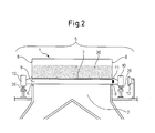
- FIG. 2 is a cross-sectional view taken along line A-A in FIG. 1 .
- the pallets 1 travel as their wheels 10 roll along two rails 26 fixedly mounted on opposite sides in the housing 31 of the sintering machine 5.
- every pallet 1 of the sintering machine 5 has a single commercially available RFID tag 11 attached to its side.
- the RFID tag 11 is preferably attached, for example, at a location in the vertical direction that is on the car 9 below the sidewall 8 and a location in the travel direction that is midway between two adjacent wheels 10 in the longitudinal direction of the sintering machine 5.
- passive RFID tags 11 This type is preferable for not requiring an internal power source and thus eliminating the nuisance of having to change batteries.
- the passive RFID tags 11 are attached to the pallets 1 made of steel, it is advisable to use UHF-band RFID tags 11 that have a long transmission distance in an on-metal condition.
- the RFID tag 11 attached to each pallet 1 is written in advance with the associated pallet number and other discrimination data.
- RFID is an abbreviation of "Radio Frequency Identification.”
- An embedded RFID an IC chip tag
- ID information in its internal memory can send and receive desired data by close-range communication using radio waves or the like.
- the desired data can be read/written from/to the memory in the RFID tag through communication with the RFID tag using an external wireless transmitter-receiver.
- a data read/write antenna 12 for transmission and reception of radio waves to and from the RFID tags 11 is fixedly installed on the housing 31 side of the sintering machine 5 with the directivity of the data read/write antenna (hereinafter sometimes called simply the "antenna") 12 oriented directly opposite the RFID tags 11 attached to the sides of the pallets.
- the distance between an RFID tag 11 attached to a pallet 1 and the antenna 12 when the RFID tag 11 passes right in front of the antenna 12 is made about 1 m, for example.
- the antenna 12 is connected to a signal processing unit 14 through a signal line RF18 and a reader/writer 13 for writing/reading data to/from the RFID tags 11.
- the signal processing unit 14 recognizes the number of the pallets 1 based on, for example, a number signal of the RFID tag 11 read by the reader/writer 13.
- the RFID tag numbers are defined to be the same as the pallet numbers, thereby eliminating the work of checking the numbers against each other.
- probe signals for requesting discrimination signals based on the aforesaid discrimination data of the RFID tags 11 are sent to the antenna 12 by the reader/writer 13 so that the antenna 12 transmits radio wave probe signals in a cycle of, for example, 1 second. After this transmitted wave is received by an RFID tag 11, the transmitted wave returned by the RFID tag 11 as a response signal is received by the antenna 12. And the antenna 12 forwards the received signal to the reader/writer 13. Next, the reader/writer 13 outputs a discrimination signal representing a number or the like to an RFID input 19 of the signal processing unit 14.
- the RFID input 19 of the signal processing unit 14 recognizes the RFID tag number, namely the pallet number, from the data contained in the discrimination signal. In addition, the RFID input 19 tags the number and other data of the discrimination signal and the time of its input and stores them in an internal memory. At this time, it is preferable to affix the order of the signals input from the reader/writer 13 to the respective saved discrimination signals because this is useful during signal processing.
- the signal processing unit 14 includes a clock (not shown). In the present embodiment, the travel velocity of the pallets 1 (pallet velocity) in the operating state of the sintering machine 5 is set at around 2,500 cm/min. Further, the number of reads per pallet 1 at this time is set at around 10 to 14.
- the number of reads per attached RFID tag 11 when a pallet 1 passes in front of the antenna 12 is set at 10 or more. This eliminates the risk of the discrimination signal of an RFID tag 11 being skipped without being read even once.
- measurement of the travel velocity of the pallets 1 is enabled by installing a speed detector 15 constituted as a PLG, for example, on the housing 31 of the sintering machine 5 (see FIG. 3 ).
- the pulse signal output by the PLG is forwarded to a velocity signal input 20 of the signal processing unit 14, as shown in FIG. 3 .
- the fact that no pallet number was input can be detected from the pallet velocity output by the speed detector 15 at the time of calculation, while, moreover, the pallet number of the defective RFID tag 11 that could not be read can be determined from the pallet numbers of the RFID tags 11 before and after the RFID tag 11 concerned. For example, if it was possible to read the number of the RFID tag 11 attached to the pallet 1 following the defective RFID tag 11, it will then be possible to interpolate the number of the single skipped RFID tag 11 insofar as the order of the pallet numbers was stored in the signal processing unit 14 beforehand.
- the speed detector 15 is used as explained above to import the pallet velocity into the signal processing unit 14 in parallel with the other data, and a misidentification prevention unit 22 capable of checking pallet velocity against the number from the RFID tag 11 (the pallet number) is provided in the signal processing unit 14 for preventing pallet number misidentification owing to read failure and the like.
- the positions of the pallets 1 in the longitudinal direction of the sintering machine 5 are identified in a pallet position computing unit 23 shown in FIG. 3 based on the arrangement order of the pallets 1 stored in advance, and the pallet number sequence and state of the pallet train P at the start of operation, which constitute the initial position, using the pallet velocity from the speed detector 15.
- the pallet train P consists of 100 pallets whose pallets 1 are assigned the numbers 1 to 100 in the order of their arrangement.
- the front end of pallet no. 1 is at a base position on the entry side of the sintering machine 5 (on the side of the raw material supply hopper 3).
- the measured value of the position based on the discrimination signal from the RFID tag 11 is considered to be correct and the method of correcting the position of the pallet 1 is adopted.
- the center of the antenna 12 installation site in the longitudinal direction of the sintering machine 5 is used as the base position.
- the method of identifying the positions of the pallets 1 using the pallet velocity value Vm detected by the speed detector 15 and the time Tm has a measurement accuracy problem because the nature of the structure of the sintering machine 5 makes it difficult to avoid slip and play. It is therefore not favorable as a pallet position identification method offering good stability and accuracy. If the accumulated error should reach a deviation equal to one pallet (1.5 m), for example, the same problem as that of the method set out in the aforesaid Patent Document 1 will arise. That is the reason for adopting the pallet position identification method of the present invention, which estimates the positions of the pallets 1 based on the discrimination signals acquired from the RFID tags 11.
- a discrimination signal including a number and other data is acquired from each pallet 1.
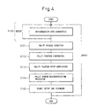
- An example of the flow of the pallet position identification processing performed by the signal processing unit 14 based on this discrimination signal will be explained based on FIG. 4 .
- the radio wave from the RFID tag 11 in response to the transmitted probe signal wave from the antenna 12 is received by the antenna 12 as a received signal wave at period ⁇ T and forwarded to the reader/writer 13.
- the reader/writer 13 extracts the response signal including the pallet number and other discrimination data from the received signal wave and forwards the response signal to the RFID input 19.
- the reader/writer 13 When no normal RFID tag 11 is present at the position opposite the antenna 12, the reader/writer 13 does not output a response signal, so no response signal containing discrimination data is received by the RFID input 19. In this case, a NULL signal containing no discrimination data is sent to the RFID input 19 at period ⁇ T.
- the discrimination signal containing the pallet number and other data from the acquired response signal and the non-detection signal (e.g., NULL) from the NULL signal are tagged with the transmit time signal Tm and sequentially stored in an internal memory as discrimination data Dm. At this time, it is preferable to affix a serial number N to each set of transmit time signal Tm, discrimination signal, etc.
- the discrimination data Dm are sequentially forwarded to the misidentification prevention unit 22 and the pallet position computing unit 23. The forgoing processing can be synchronized with the clock signal (timing signal) output by the clock incorporated in the measurement controller 24.
- the RFID input 19 When the RFID input 19 consecutively receives the aforesaid "NULL" a predetermined number of times, e.g., three times, it deems the pallet (the attached RFID tag) to have completed passage and generates a pallet pass signal Vps.
- the RFID input 19 sequentially forwards the pallet pass signals Vps to the misidentification prevention unit 22.
- the pallet pass signals Vps can also be forwarded to the pallet position computing unit 23.
- the forgoing processing can be synchronized with the clock signal (timing signal) output by the clock incorporated in the measurement controller 24.
- the pallet position computing unit 23 does a calculation using the discrimination data Dm from the RFID tag of one pallet among the discrimination data Dm successively acquired from the RFID input 19 to obtain an intermediate time between, for example, the first receive time and the last receive time and finds that the line longitudinal direction center of the pallet 1 bearing the RFID tag 11 was positioned in front of the antenna 12 at the calculated time.
- the pallet pass signal Vps can be used as a trigger signal or the like.
- the error between the pallet position for a given pallet calculated from the pallet velocity in this manner and the pallet position found in S102 is calculated, and when the error is less than ⁇ X cm, the pallet position calculated from the pallet velocity is output as being correct.
- the error is equal to or greater than the allowable range ⁇ X cm, the pallet position identified in S102 is deemed correct and the current positions of the individual pallets in the sintering machine calculated from the pallet velocity are corrected by the amount of error.
- X 10 cm is given as an example in the present embodiment, the value of X can be suitably defined in light of the desired position detection accuracy.
- the misidentification prevention unit checks the measured value of the pallet position derived in S103 based on the measured pallet velocity value produced by the speed detector 15 against the discrimination data Dm obtained in S100 and executes processing for preventing misidentification that may occur at the time of deriving the pallet number based on the pallet velocity owing to, for example, the response signal not being read or other such transmit/receive error between the RFID tag and the reader/writer 13.
- This misidentification processing is preferably utilized when the means for position detection is mainly the pallet number derived based on the pallet velocity obtained from the speed detector 15.
- the response signal from the RFID tag is the primary position detection means, use of the misidentification processing is not always necessary.
- the calculation results and derivation results obtained by the aforesaid processing operations are output through an output unit 25 to a computer display for viewing by the operator, for instance, and to a recording device.
- the aforesaid processing enhances the accuracy with which the positions of the pallets 1 are identified, it was discovered through offline experiments carried out in advance that the read status varies subtly with, inter alia, the RFID tag 11 orientation, the antenna 12 orientation, and the height relationship between the two.
- the installation of the RFID tags 11 and antenna 12 should be done with utmost care to the orientation and location of the devices.
- the signal processing unit 14 comprises the RFID input 19, velocity signal input 20, pallet number misidentification prevention unit 22, pallet position computing unit 23, measurement controller 24, and output unit 25 (see FIG. 3 ).
- the signal processing unit 14 can be configured as a computer system.
- the computer system should include a CPU, main memory, HDD or other external storage, input devices such as a keyboard and mouse, and a computer display.
- the sintering machine pallet position identification device of the present invention can be embodied by creating a computer program for executing the sequence of processing operations for pallet position identification set out in S100 to S105 in the computer system and loading the program in the main memory.
- FIGs. 5 to 8 An embodiment of the pallet air leakage detector for a sintering machine that is the second invention of this application will be explained in detail with reference to FIGs. 5 to 8 .
- the air leakage detector of the present embodiment is equipped with the pallet position identification device of the first invention set out in the foregoing.
- devices and constituents having the same functions as those in the foregoing drawings are assigned the same symbols
- FIG. 5 shows a sintering machine 5 provided with the air leakage detector according to the present invention, in which (a) is a plan view and (b) a side view.
- the sintering machine 5 is equipped with a pallet train P made up of many pallets 1 concatenated in the longitudinal direction and capable of moving in the longitudinal direction and with suction means consisting of multiple window boxes 2 fixedly installed under the pallet train P.
- each pallet 1 has rows of grate bars 7 on its floor and is equipped with wheels 10 on the outside of sidewalls 8 installed on opposite sides to sandwich the grate bars 7.
- FIG. 10 shows a pallet train P made up of many pallets 1 concatenated in the longitudinal direction and capable of moving in the longitudinal direction and with suction means consisting of multiple window boxes 2 fixedly installed under the pallet train P.
- each pallet 1 has rows of grate bars 7 on its floor and is equipped with wheels 10 on the outside of sidewalls 8 installed on opposite sides to sandwich the grate bars 7.
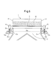
- FIG. 6 is a cross-sectional view taken along line B-B in FIG. 5 .
- the cross-sectional view taken along line A-A in FIG. 5 is the same as FIG.
- the present embodiment is equipped with the pallet position identification device 32 explained in the first embodiment. Further, the pallets 1 travel as the wheels 10 provided on their opposite sides roll along two rails 26 fixedly mounted on opposite sides in the housing 31 of the sintering machine 5. In the explanation of the present embodiment that follows, explanation regarding the pallet position identification device 32 is omitted because it would be the same as that regarding the first embodiment.
- a light emitter 16a for emitting a laser beam and a light receiver 16b for detecting the laser beam of a laser oxymeter 16 like that described in, for example, Non-patent Document 1 Kurimoto Technical Report No.56, pp17-18 ) are installed at the uppermost parts of those side walls 2a of the window box 2 that extend in the line direction of the sintering machine 5 (travel direction of the pallets 1) to be positioned immediately under the pallets 1 and oppose each other in the width direction of the pallets 1.
- the laser oxymeter 16 is installed at the upper part of the side walls 2a because leaking air flowing into the window box 2 from the pallet 1 diffuses as it drawn downward toward the suction pipe 17, so that in order to determine the air leakage site of the pallet 1 by the oxygen concentration measurement, it is preferable for the laser oxymeter 16 to be as close to the pallet 1 as possible.
- the uniformity of the air leakage detection in the width direction of the pallet 1 is preferably enhanced by making the optical axis 16c of the laser beam parallel to the direction connecting the light emitter 16a and light receiver 16b lie horizontal to the ground and parallel to the floor of the pallet 1.
- the light emitter 16a and light receiver 16b are installed so that the optical axis 16c lies perpendicular to the line longitudinal direction of the sintering machine 5.
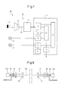
- FIG. 7 shows the configuration of the air leakage detector 33 of this embodiment.
- This air leakage detector 33 is equipped with the pallet position identification device 32 shown in FIG. 3 discussed earlier.
- the laser oxymeter 16 is connected to the measurement controller 24 through an oxygen concentration signal input 21, and the oxygen concentration measurement is conducted under the control of the measurement controller 24.
- a data processing unit 41 is connected to the laser oxymeter 16 for detecting the presence/absence and magnitude of air leakage for every train pallet based on the oxygen concentration measurement.
- the data processing unit 41 is constituted as, for example, a personal computer or the like.
- through-holes are formed in the pedestals 26a of the rails 26 on which the wheels 10 roll on opposite sides and at opposing locations in the side walls 2a of the window boxes 2, purge tubes 27 are passed through the respective through-holes, and the light emitter 16a is connected through one flange 28 to the end of one purge tube 27 and the light receiver 16b is connected through another flange 28 to the end of the other purge tube 27.
- Protective seal glass windows 29 are provided on the optical axes at the beam outlet of the light emitter 16a and the beam inlet of the light receiver 16b.
- nitrogen gas is blown as purge gas through the purge tubes 27 away from the seal glass windows 29 of the light emitter 16a and light receiver 16b toward the interior of the window box 2.
- the flow rate of the blown nitrogen gas is regulated so that the blown-in nitrogen gas does not substantially affect the composition of the exhaust gas. Any gas that does not adversely affect the oxygen concentration measurement can be used as the purge gas in place of nitrogen gas.
- the oxygen concentration in the window boxes 2 of the sintering machine 5 is 17 to nearly 20% on the sinter raw material supply side (feed side: upstream side in the direction of pallet travel) of the longitudinal direction of the sintering machine 5 shown in FIG. 5 , gradually declines to 10% or less approaching the middle region in the longitudinal direction, and then rises again to reach nearly 21% on the discharge side (downstream side in the direction of pallet travel).
- the laser oxymeter 16 at a location where the difference between the normal state with no air leakage due to deterioration of the pallet 1 and the abnormal state with air leakage is likely to be most pronounced, namely at the middle region in the longitudinal direction of the sintering machine 5 where the oxygen concentration is normally stable at a low level.
- installation at the middle region should be impossible for lack of space, detection of air leakage is possible even where the oxygen concentration is high by carefully selecting an installation site where the concentration is stable.
- the middle region it is better from the viewpoint of the heat resistance and maintainability of the light emitter 16a and light receiver 16b of the laser oxymeter 16 to make the installation closer to the feed side because the ambient temperature of the window boxes 2 is higher with increasing proximity to the discharge side.
- the amount of dust in the exhaust gas in the window boxes 2 is lower on feed side, which is advantageous in the point that the risk of dust-induced laser beam attenuation and clogging of the purge tubes 27 is lower.
- the laser oxymeter 16 was installed in the seventh window box 2 from the feed side. While the oxygen concentration at this installation site is around 7% in normal operation, the value rose to 8 or 9% during passage of a pallet 1 with air leakage. In this case, therefore, the operator should be warned of air leakage by issuing an alarm when the oxygen concentration rises to 8% or greater.
- the laser beam of the laser oxymeter 16 used has an adequately small diameter of about 20 mmF and the laser response time is about 3 seconds.
- the oxygen concentration measurement values obtained with the laser oxymeter 16 can be used not only to determine which pallets 1 of the pallet train P are leaking air but even to determine the locations of the air leaks in the travel direction of the so-determined pallets 1.
- the pallet position data and the oxygen concentration data can be imported through an I/O board into the data processing unit 41 constituted using a personal computer or the like to detect air leakage from abnormal oxygen concentration values and display the results together with the numbers of the pallets that have developed air leaks on the computer screen.
- the air leakage detector 33 for a sintering machine that is the second embodiment of the present invention enables high-sensitivity measurement of the oxygen concentration in the window box using the laser oxymeter 16, thereby enabling high-sensitivity detection of air leakage in the pallets passing over the site of the light emitter 16a and light receiver 16b of the laser oxymeter 16.
- the provision of the pallet position identification device 32 explained in the first embodiment makes it possible to determine the number and the like of the pallets passing over the site of the light emitter 16a and light receiver 16b of the laser oxymeter 16 and even to determine the locations of any air leaks in the travel direction of the pallets with high accuracy.
- the number of runs n written in the RFID tag 11 is read together with the number of the RFID tag 11 at every passage of the RFID tag 11 in front of the antenna 12, and, utilizing the fact that the RFID tags 11 enable writing of data, the number of runs of each passing RFID tag 11 is incremented by one to write n + 1 thereto under the control of, for example, the signal processing unit 14. This makes it possible to monitor the number of runs of the individual pallets 1 on the line of the sintering machine 5 and is therefore useful for deciding the maintenance order of the pallets 1.
- the sintering machine pallet air leakage detector 33 explained as the second embodiment detects air leakage by the method of measuring the oxygen concentration in a window box 2 with a laser oxymeter, it can also obviously be configured by adopting any other known air leakage detection method instead.
- the pallet position identification device of the present invention and the air leakage detector utilizing this device were explained in detail in the foregoing as technologies for detecting air leakage attributable to pallets in the sintering process for producing sintered ore in the blast-furnace ironmaking that is a process of the steelmaking industry.
- the pallet position identification device and air leakage detector of the present invention are apparently also applicable for the detection of the position of moving devices and the detection of device gas inflow in other steel industry processes as well as similar processes and the like in other industries.
Landscapes
- Engineering & Computer Science (AREA)
- Chemical & Material Sciences (AREA)
- Mechanical Engineering (AREA)
- Geochemistry & Mineralogy (AREA)
- Geology (AREA)
- Life Sciences & Earth Sciences (AREA)
- Manufacturing & Machinery (AREA)
- General Life Sciences & Earth Sciences (AREA)
- Materials Engineering (AREA)
- Environmental & Geological Engineering (AREA)
- Metallurgy (AREA)
- Organic Chemistry (AREA)
- General Engineering & Computer Science (AREA)
- Manufacture And Refinement Of Metals (AREA)
Abstract
Description
- This invention relates to a method of preventing air leakage from a sintering machine, specifically to an optimum technology for use in detecting air leakage ascribable to a sintering machine pallet or pallets by accurately identifying the positions of pallets loaded with raw material for forming charged beds of the raw material and endlessly circulating above the sintering machine, and combining an appropriate air leakage detection method with the position identification.
- As shown in
FIG. 9 , a sintering machine used in the iron and steel industry is equipped with a pallet train P made up ofmany pallets 1 concatenated in the longitudinal direction of asintering machine 5 and capable of moving in the longitudinal direction and with suction means consisting ofmultiple window boxes 2 fixedly installed under and in parallel with the pallet train P. As shown in the perspective view ofFIG. 10 , eachpallet 1 has rows ofgrate bars 7 on its floor and is equipped withwheels 10 on the outside ofsidewalls 8 installed on opposite sides to sandwich thegrate bars 7. As shown inFIG. 9(b) , the front and rear ends of the pallet train P are connected to establish a structure that endlessly circulates inside thehousing 31 of thesintering machine 5.FIG. 9(a) is a plan view and (b) a side view of thesintering machine 5. The pressure in thewindow boxes 2 is reduced through asuction pipe 17 by the suction/exhaust operation of a blower (not shown in the drawings). As the pallet train P circulates, thepallets 1 are loaded with sinter raw material containing coke powder supplied from a raw material supply hopper 3. The surfaces of the sinter raw material beds are ignited by anignition furnace 4 and air is simultaneously sucked in through thewindow boxes 2. As a result of this air intake, the combustion zone of the sinter raw material bed 30 (FIG. 11 ) advances from the upper surface downward to continuously produce sintered ore.FIG. 11 shows apallet 1 and awindow box 2 viewed in the longitudinal direction of thesintering machine 5, namely a cross-sectional view of thesintering machine 5. The pallet train P is able to travel in the longitudinal direction of thesintering machine 5 because thewheels 10 installed on thepallets 1 roll along tworails 26 fixedly mounted on opposite sides in thehousing 31 of thesintering machine 5. - Although this
sintering machine 5 has the advantage of enabling continuous production of sintered ore, it has the disadvantage of being difficult to maintain as an airtight structure owing to, inter alia, the effects of damage to thegrate bars 7 installed at the floor of thepallets 1, gaps of thesidewall 8 connectors betweenadjacent pallets 1, and wear of the pallet seal bars 6 (seeFIG. 11 ). In other words, gaps occur at these regions to give rise to the problem that a large amount of ineffectual air (leaking air) not passing through the sinterraw material beds 30 and not contributing to sintering flows into thewindow boxes 2. As wasted power consumption increases during sintered ore production in proportion as this air leakage increases, the economy of the operation is markedly impaired. - Various methods have therefore been improvised for detecting air leakage, like those set out in
Patent Documents - Patent Document 3 sets out an invention of a method of detecting the sintering combustion front grate arrival position. The sintering machine pallet position identification method set out in Patent Document 3 employs a pallet sensor using a microswitch or the like. The pallet sensor is located at a certain position traversed by the sintering machine pallets on the upper side and detects a particular part of the individual pallets passing over the pallet sensor, e.g. detects the pallet front ends in the direction of travel. First, the pallet number of the pallet above the pallet sensor is stored in memory, and when the next pallet is detected by the pallet sensor, the pallet number of a pallet number order list stored in memory beforehand is updated and the current time is stored. This process is repeated and the travel velocity of the pallets is calculated from the passage time difference and the length per pallet. The position of a specific pallet is calculated from the travel speed as, for instance, its distance from the ignition furnace.
-
Patent Document 4 describes use of an REID tag to detect passage of an object.Patent Document 4 is directed to a technique for detecting passage of an object, not for detecting its position.Patent Document 5 describes reading and writing of moving body data using an RFID tag and antenna, and an RFID reader/writer. However, the technology set out inPatent Document 5 is not for detecting position but for enabling reading and writing of a large volume of data between an RFID tag and an RFID reader/writer moving at high speed relative to each other, by aligning multiple antennas in the direction of moving body travel so as to expand the reader/writer detection area. -
-
Patent Document 1 - Unexamined Patent Publication (Kokai) No.
61-195929 -
Patent Document 2 - Unexamined Patent Publication (Kokai) No.
11-264027 - Patent Document 3
- Unexamined Patent Publication (Kokai) No.
59-185739 -
Patent Document 4 - Unexamined Patent Publication (Kokai) No.
2008-052411 -
Patent Document 5 - Unexamined Patent Publication (Kokai) No.
2006-172101 -
- Non-patent
Document 1 - Kurimoto Technical Report No.56, pp17-18
- However, since the "sintering machine pallet position identification method" set out in Patent Document 3 employs a pallet sensor using a microswitch or similar, if a pallet identification failure or a double data read should occur even once for some reason, the identified position will be inaccurate by one whole pallet or more. As a result, a pallet that is not leaking will be repaired and one that requires repair will be left online as is, so air leakage will not be eliminated.
- The pallet train of an ordinary sintering machine actually includes 100 or more pallets that make one round in the sintering machine about once every 90 minutes. The pallet sensor must therefore detect the passage of 1,600 or more pallets daily. Since a sintering machine is usually operated continuously for 30 days or more, the number of identifications per month reaches as high as 50,000. A pallet sensor that employs a microswitch or other device that repeatedly switches ON/OFF mechanically therefore has a problem in the point of durability. Moreover, the environment around the sintering machine, which is marked by high temperature, high humidity and heavy dust, is a very severe one for a sensor. Maintaining a pallet sensor of the conventional type at high sensitivity and in normal condition over a long period is therefore not easy.
- In view of the foregoing problems of the conventional sintering machine pallet position identification devices, the first object of the present invention is to provide a sintering machine pallet position identification device that can stably and accurately identify the positions of pallets endlessly circulating in a sintering machine over a long period of time. The second object is to provide an air leakage detector for a sintering machine equipped with the pallet position identification device that can stably and accurately detect air leakage attributable to a pallet over a long period of time.
- The gist of the present invention is as set out in the following.
- The sintering machine pallet position identification device of the present invention, which is part of an air leakage detector of a sintering machine comprising an endless pallet train constituted of multiple movable pallets for carrying sinter raw material concatenated in the direction of travel with its front and rear ends connected together, multiple window boxes fixed to a housing to be disposed under the pallet train, and a suction pipe connected to the lower ends of the individual window boxes for exhausting gas from the window boxes, and which detects the positions in the sintering machine longitudinal direction of the individual pallets circulating inside the sintering machine, is characterized by comprising RFID tags capable of writing/reading discrimination data mounted on outsides of the sidewalls of the individual pallets, an antenna fixed on the sintering machine housing to face the pallet train at a position where it can transmit/receive radio waves to/from the RFID tags mounted on the circulating pallets for a predetermined time period, an RFID tag reader/writer connected to the antenna that is capable of writing/reading signals containing the discrimination data of the RFID tags, and a signal processing unit for discriminating each pallet passing the antenna position and detecting and identifying the position of the pallet based on the discrimination data of the RFID tag acquired from the reader/writer.
- Moreover, the sintering machine pallet position identification device of the present invention is characterized in that the RFID tag reader/writer periodically transmits probe signals requesting the discrimination data to the RFID tags through the antenna, obtains the discrimination data from the received waves returned by the RFID tags and forwards the discrimination data to the signal processing unit as discrimination signals, and the signal processing unit uses predefined pallet train arrangement information to derive the number and position in the sintering machine longitudinal direction of the individual pallets based on the discrimination signals acquired periodically.
- In addition, the sintering machine pallet position identification device of the present invention is characterized in that it comprises a velocity detector for detecting the travel velocities of the pallets and the signal processing unit derives the number and position in the sintering machine longitudinal direction of the individual pallets based on the pallet travel velocities acquired from the velocity detector and the pallet train arrangement information.
- The air leakage detector for a sintering machine of the present invention is equipped with the aforesaid sintering machine pallet position identification device and is characterized by comprising one or multiple laser oxymeters each having a light emitter and a light receiver mounted on top of window box walls opposing in a direction perpendicular to the sintering machine longitudinal direction to face each other in the width direction of the pallets and emitting a laser beam from the light emitter to be received by the light receiver for measuring oxygen concentration in the light path, and a data processing unit that uses the value of oxygen concentration in the window boxes measured by the laser oxymeter and the position data of the individual train pallets obtained by the pallet position identification device to detect the presence/absence and magnitude of air leakage for every train pallet.
- The pallet position identification device of the present invention set out in the foregoing enables the positions of pallets endlessly circulating in a sintering machine to be stably and accurately identified over a long period of time. And the air leakage detector equipped with the pallet position identification device enables air leakage attributable to the pallets to be stably and accurately detected over a long period of time.
- Moreover, the air leakage detection using the pallet position identification device of the present invention enables accurate detection of air leakage caused by damage or the like sustained by the grate bars installed on the floor of the pallets, air leakage from the sidewall connectors between adjacent pallets, and air leakage due to wear of the pallet seal bars, and also makes it possible to identify a pallet that is leaking air without fail. Air leakage can therefore be reduced to a much greater extent and more consistently than in the past by replacing and repairing the pallets determined to be leaking air. As a result, the amount of power consumed by the main sinter exhaust blower can be reduced, while also increasing sintered ore production thanks to the greater amount of air sucked normally through the sinter pallets.
-
-
FIG. 1(a) is plan view of a sintering machine provided with the pallet position identification device of the present invention. -
FIG. 1(b) is a side view of the sintering machine provided with the pallet position identification device of the present invention. -
FIG. 2 is a cross-sectional view taken along line A-A inFIG. 1(a) . -
FIG. 3 is a block diagram schematically illustrating the system configuration of the pallet position identification device of the present invention. -
FIG. 4 is a measurement processing flowchart of the pallet position identification device of the present invention. -
FIG. 5(a) is a plan view of a sintering machine provided with a pallet position identification device and air leakage detector of the present invention. -
FIG. 5(b) is a side view of the sintering machine provided with a pallet position identification device and air leakage detector of the present invention. -
FIG. 6 is a cross-sectional view taken along line B-B inFIG. 5(a) . -
FIG. 7 is a block diagram schematically illustrating the system configuration of the air leakage detector of the present invention. -
FIG. 8 is an enlarged view of the laser oxymeter portion ofFIG. 6 . -
FIG. 9(a) is a plan view of a conventional sintering machine. -
FIG. 9(b) is a side view of the conventional sintering machine. -
FIG. 10 is a perspective view of a pallet. -
FIG. 11 is a cross-sectional view taken along line - C-C in
FIG. 9(a) . - Embodiments of the sintering machine pallet position identification device of the present invention and sintering machine air leakage detector equipped with the pallet position identification device will be explained in detail with reference to the drawings in the following. In the interest of simplicity and clarity of the explanation of the drawing contents, constituents and the like having identical functions are assigned the same symbols throughout the drawings.
- The configuration of an embodiment of the sintering machine pallet position identification device of the present invention is illustrated schematically in
FIGs. 1 to 3 .FIG. 1 shows asintering machine 5 equipped with a position identification device according to the present invention, in which (a) is a plan view and (b) a side view. As shown inFIG. 1 , thesintering machine 5 is equipped with a pallet train P made up ofmany pallets 1 concatenated in the longitudinal direction and capable of moving in the longitudinal direction and with suction means consisting ofmultiple window boxes 2 fixedly installed under the pallet train P. As shown inFIG. 10 , eachpallet 1 has rows ofgrate bars 7 on its floor and is equipped withwheels 10 on the outside ofsidewalls 8 installed on opposite sides to sandwich the grate bars 7. As shown inFIG. 1(b) , the front and rear ends of the pallet train P are connected to establish a structure that endlessly circulates inside thehousing 31 of thesintering machine 5. The pressure in thewindow boxes 2 is reduced through asuction pipe 17 by the suction/exhaust operation of a blower (not shown in the drawings). As the pallet train P circulates, thepallets 1 are loaded with sinter raw material containing coke powder supplied from a raw material supply hopper 3. The surfaces of the sinter raw material beds are ignited by anignition furnace 4 and air is sucked in through thewindow boxes 2.FIG. 2 is a cross-sectional view taken along line A-A inFIG. 1 . Thepallets 1 travel as theirwheels 10 roll along tworails 26 fixedly mounted on opposite sides in thehousing 31 of thesintering machine 5. - In the present invention, as shown in
FIGs. 1 and2 , everypallet 1 of thesintering machine 5 has a single commerciallyavailable RFID tag 11 attached to its side. TheRFID tag 11 is preferably attached, for example, at a location in the vertical direction that is on thecar 9 below thesidewall 8 and a location in the travel direction that is midway between twoadjacent wheels 10 in the longitudinal direction of thesintering machine 5. In the present embodiment, it is advisable to use passive RFID tags 11. This type is preferable for not requiring an internal power source and thus eliminating the nuisance of having to change batteries. Further, since the passive RFID tags 11 are attached to thepallets 1 made of steel, it is advisable to use UHF-band RFID tags 11 that have a long transmission distance in an on-metal condition. TheRFID tag 11 attached to eachpallet 1 is written in advance with the associated pallet number and other discrimination data. - "RFID" is an abbreviation of "Radio Frequency Identification." An embedded RFID (an IC chip tag) storing ID information in its internal memory can send and receive desired data by close-range communication using radio waves or the like. The desired data can be read/written from/to the memory in the RFID tag through communication with the RFID tag using an external wireless transmitter-receiver.
- On the other hand, as shown in
FIGs. 1 and2 , a data read/write antenna 12 for transmission and reception of radio waves to and from the RFID tags 11 is fixedly installed on thehousing 31 side of thesintering machine 5 with the directivity of the data read/write antenna (hereinafter sometimes called simply the "antenna") 12 oriented directly opposite the RFID tags 11 attached to the sides of the pallets. The distance between anRFID tag 11 attached to apallet 1 and theantenna 12 when theRFID tag 11 passes right in front of theantenna 12 is made about 1 m, for example. As shown inFIG. 3 , theantenna 12 is connected to asignal processing unit 14 through a signal line RF18 and a reader/writer 13 for writing/reading data to/from the RFID tags 11. When apallet 1 with anRFID tag 11 attached passes near the front of theantenna 12, thesignal processing unit 14 recognizes the number of thepallets 1 based on, for example, a number signal of theRFID tag 11 read by the reader/writer 13. In the present embodiment, the RFID tag numbers are defined to be the same as the pallet numbers, thereby eliminating the work of checking the numbers against each other. - The configuration of the pallet
position identification device 32 shown inFIG. 3 will be explained in detail. In the present embodiment, probe signals for requesting discrimination signals based on the aforesaid discrimination data of the RFID tags 11 are sent to theantenna 12 by the reader/writer 13 so that theantenna 12 transmits radio wave probe signals in a cycle of, for example, 1 second. After this transmitted wave is received by anRFID tag 11, the transmitted wave returned by theRFID tag 11 as a response signal is received by theantenna 12. And theantenna 12 forwards the received signal to the reader/writer 13. Next, the reader/writer 13 outputs a discrimination signal representing a number or the like to anRFID input 19 of thesignal processing unit 14. TheRFID input 19 of thesignal processing unit 14 recognizes the RFID tag number, namely the pallet number, from the data contained in the discrimination signal. In addition, theRFID input 19 tags the number and other data of the discrimination signal and the time of its input and stores them in an internal memory. At this time, it is preferable to affix the order of the signals input from the reader/writer 13 to the respective saved discrimination signals because this is useful during signal processing. Thesignal processing unit 14 includes a clock (not shown). In the present embodiment, the travel velocity of the pallets 1 (pallet velocity) in the operating state of thesintering machine 5 is set at around 2,500 cm/min. Further, the number of reads perpallet 1 at this time is set at around 10 to 14. Calculating from the transmit/receive cycle (1 sec) and the pallet velocity, this means that the RFID tags 11 within a range of travel of about 20 to 30 (2,500 / (10 - 14) cm to the left and right (i.e., in the sintering machine longitudinal direction) of the center of theantenna 12 are the ones read. As eachpallet 1 ordinarily measures 1.5 m in the longitudinal direction, it follows that theRFID tag 11 attached to anadjacent pallet 1 will not be read by mistake. The functions required for measurement incorporated in the reader/writer 13,RFID input 19, and constituents contained in thesignal processing unit 14 explained in the following are implemented under the control of ameasurement controller 24. - As explained in the foregoing, when signals are exchanged between an
RFID tag 11 and theantenna 12, it is necessary to avoid superimposition of signals from adjacent RFID tags 11. Among the acceptable intervals L, there is therefore a certain minimum value L0. This minimum interval L0 is determined by the radio wave transmit/receive directivities of theantenna 12 and RFID tags 11, and the shortest distance between theantenna 12 and moving RFID tags 11. It suffices to suitably define the interval L of the RFID tags 11 and the interval between theantenna 12 and the pallet train P to fall within the range of (interval L > minimum interval L0). - In the present embodiment, as pointed out above, the number of reads per attached
RFID tag 11 when apallet 1 passes in front of theantenna 12 is set at 10 or more. This eliminates the risk of the discrimination signal of anRFID tag 11 being skipped without being read even once. - Moreover, in the present embodiment, measurement of the travel velocity of the pallets 1 (pallet velocity) is enabled by installing a
speed detector 15 constituted as a PLG, for example, on thehousing 31 of the sintering machine 5 (seeFIG. 3 ). The pulse signal output by the PLG, for example, is forwarded to avelocity signal input 20 of thesignal processing unit 14, as shown inFIG. 3 . If the reading of a discrimination signal including a pallet number should be skipped owing to, for example, adefective RFID tag 11, the fact that no pallet number was input can be detected from the pallet velocity output by thespeed detector 15 at the time of calculation, while, moreover, the pallet number of thedefective RFID tag 11 that could not be read can be determined from the pallet numbers of the RFID tags 11 before and after theRFID tag 11 concerned. For example, if it was possible to read the number of theRFID tag 11 attached to thepallet 1 following thedefective RFID tag 11, it will then be possible to interpolate the number of the single skippedRFID tag 11 insofar as the order of the pallet numbers was stored in thesignal processing unit 14 beforehand. In the present embodiment, thespeed detector 15 is used as explained above to import the pallet velocity into thesignal processing unit 14 in parallel with the other data, and amisidentification prevention unit 22 capable of checking pallet velocity against the number from the RFID tag 11 (the pallet number) is provided in thesignal processing unit 14 for preventing pallet number misidentification owing to read failure and the like. - The positions of the
pallets 1 in the longitudinal direction of thesintering machine 5 are identified in a palletposition computing unit 23 shown inFIG. 3 based on the arrangement order of thepallets 1 stored in advance, and the pallet number sequence and state of the pallet train P at the start of operation, which constitute the initial position, using the pallet velocity from thespeed detector 15. Assume, for example, that the pallet train P consists of 100 pallets whosepallets 1 are assigned thenumbers 1 to 100 in the order of their arrangement. Further assume that in the state at the start of operation at a given time T0, the front end of pallet no. 1 is at a base position on the entry side of the sintering machine 5 (on the side of the raw material supply hopper 3). Based on the foregoing information on the arrangement of the pallet train P, when using anRFID tag 11 attached to apallet 1 for performing position identification at a given time Tm, it is possible to calculate the travel distance Lm (Lm = Vm x (Tm - T0)) of the pallet concerned in thesintering machine 5 from the detected velocity value Vm of thespeed detector 15 and time (Tm - T0) and to derive the position of thepallet 1 concerned relative to the base position from the travel distance Lm and the distance between pallet no. 1 and the pallet concerned. In the present embodiment, in the case where the difference between this calculated position and the derived value of the position of thepallet 1 derived by the processing explained in the following based on the discrimination signal acquired from theRFID tag 11 attached to thepallet 1 concerned shows a deviation of 10 cm or greater, the measured value of the position based on the discrimination signal from theRFID tag 11 is considered to be correct and the method of correcting the position of thepallet 1 is adopted. Instead of the aforesaid base position, it is possible to use the center of theantenna 12 installation site in the longitudinal direction of thesintering machine 5 as the base position. - The method of identifying the positions of the
pallets 1 using the pallet velocity value Vm detected by thespeed detector 15 and the time Tm has a measurement accuracy problem because the nature of the structure of thesintering machine 5 makes it difficult to avoid slip and play. It is therefore not favorable as a pallet position identification method offering good stability and accuracy. If the accumulated error should reach a deviation equal to one pallet (1.5 m), for example, the same problem as that of the method set out in theaforesaid Patent Document 1 will arise. That is the reason for adopting the pallet position identification method of the present invention, which estimates the positions of thepallets 1 based on the discrimination signals acquired from the RFID tags 11. - In the pallet position identification device of the present embodiment, a discrimination signal including a number and other data is acquired from each
pallet 1. An example of the flow of the pallet position identification processing performed by thesignal processing unit 14 based on this discrimination signal will be explained based onFIG. 4 . - First, based on a probe signal output by the reader/
writer 13 under the control of theRFID input 19 for requesting the discrimination signal, a transmitted probe signal wave is transmitted from theantenna 12 toward the side of thepallet 1 at transmit (or receive) time Tm (m = 0, 1, 2 ...) of period ΔT at, for example, one-second intervals. Next, the radio wave from theRFID tag 11 in response to the transmitted probe signal wave from theantenna 12 is received by theantenna 12 as a received signal wave at period ΔT and forwarded to the reader/writer 13. The reader/writer 13 extracts the response signal including the pallet number and other discrimination data from the received signal wave and forwards the response signal to theRFID input 19. When nonormal RFID tag 11 is present at the position opposite theantenna 12, the reader/writer 13 does not output a response signal, so no response signal containing discrimination data is received by theRFID input 19. In this case, a NULL signal containing no discrimination data is sent to theRFID input 19 at period ΔT. In theRFID input 19, the discrimination signal containing the pallet number and other data from the acquired response signal and the non-detection signal (e.g., NULL) from the NULL signal are tagged with the transmit time signal Tm and sequentially stored in an internal memory as discrimination data Dm. At this time, it is preferable to affix a serial number N to each set of transmit time signal Tm, discrimination signal, etc. In addition, the discrimination data Dm are sequentially forwarded to themisidentification prevention unit 22 and the palletposition computing unit 23. The forgoing processing can be synchronized with the clock signal (timing signal) output by the clock incorporated in themeasurement controller 24. - When the
RFID input 19 consecutively receives the aforesaid "NULL" a predetermined number of times, e.g., three times, it deems the pallet (the attached RFID tag) to have completed passage and generates a pallet pass signal Vps. TheRFID input 19 sequentially forwards the pallet pass signals Vps to themisidentification prevention unit 22. The pallet pass signals Vps can also be forwarded to the palletposition computing unit 23. The forgoing processing can be synchronized with the clock signal (timing signal) output by the clock incorporated in themeasurement controller 24. - The pallet
position computing unit 23 does a calculation using the discrimination data Dm from the RFID tag of one pallet among the discrimination data Dm successively acquired from theRFID input 19 to obtain an intermediate time between, for example, the first receive time and the last receive time and finds that the line longitudinal direction center of thepallet 1 bearing theRFID tag 11 was positioned in front of theantenna 12 at the calculated time. In this processing, the pallet pass signal Vps can be used as a trigger signal or the like. - On the other hand, owing to the fact that the detected velocity value Vm produced by the
speed detector 15 is forwarded to thevelocity signal input 20, the palletposition computing unit 23 can use the detected velocity value Vm and the time from the start of the measurement (Tm - T0) to calculate the travel distance Lm (Lm = Vm x (Tm - T0)) of pallet no. 1 (leading pallet of the train) in the sintering machine and calculate the positions of the individual pallets relative to the base position from the travel distance Lm and distance between pallet no. 1 and the respective pallets. The error between the pallet position for a given pallet calculated from the pallet velocity in this manner and the pallet position found in S102 is calculated, and when the error is less than ±X cm, the pallet position calculated from the pallet velocity is output as being correct. When the error is equal to or greater than the allowable range ±X cm, the pallet position identified in S102 is deemed correct and the current positions of the individual pallets in the sintering machine calculated from the pallet velocity are corrected by the amount of error. Although X = 10 cm is given as an example in the present embodiment, the value of X can be suitably defined in light of the desired position detection accuracy. - The misidentification prevention unit checks the measured value of the pallet position derived in S103 based on the measured pallet velocity value produced by the
speed detector 15 against the discrimination data Dm obtained in S100 and executes processing for preventing misidentification that may occur at the time of deriving the pallet number based on the pallet velocity owing to, for example, the response signal not being read or other such transmit/receive error between the RFID tag and the reader/writer 13. This misidentification processing is preferably utilized when the means for position detection is mainly the pallet number derived based on the pallet velocity obtained from thespeed detector 15. When the response signal from the RFID tag is the primary position detection means, use of the misidentification processing is not always necessary. - The calculation results and derivation results obtained by the aforesaid processing operations are output through an
output unit 25 to a computer display for viewing by the operator, for instance, and to a recording device. - Although the aforesaid processing enhances the accuracy with which the positions of the
pallets 1 are identified, it was discovered through offline experiments carried out in advance that the read status varies subtly with, inter alia, theRFID tag 11 orientation, theantenna 12 orientation, and the height relationship between the two. When implementing the present invention, therefore, the installation of the RFID tags 11 andantenna 12 should be done with utmost care to the orientation and location of the devices. - As explained in the foregoing, the
signal processing unit 14 comprises theRFID input 19,velocity signal input 20, pallet numbermisidentification prevention unit 22, palletposition computing unit 23,measurement controller 24, and output unit 25 (seeFIG. 3 ). Thesignal processing unit 14 can be configured as a computer system. The computer system should include a CPU, main memory, HDD or other external storage, input devices such as a keyboard and mouse, and a computer display. The sintering machine pallet position identification device of the present invention can be embodied by creating a computer program for executing the sequence of processing operations for pallet position identification set out in S100 to S105 in the computer system and loading the program in the main memory. - An embodiment of the pallet air leakage detector for a sintering machine that is the second invention of this application will be explained in detail with reference to
FIGs. 5 to 8 . The air leakage detector of the present embodiment is equipped with the pallet position identification device of the first invention set out in the foregoing. In the interest of simplicity of the drawings used in the following explanation, devices and constituents having the same functions as those in the foregoing drawings are assigned the same symbols -
FIG. 5 shows asintering machine 5 provided with the air leakage detector according to the present invention, in which (a) is a plan view and (b) a side view. As shown inFIG. 5 , thesintering machine 5 is equipped with a pallet train P made up ofmany pallets 1 concatenated in the longitudinal direction and capable of moving in the longitudinal direction and with suction means consisting ofmultiple window boxes 2 fixedly installed under the pallet train P. As shown inFIG. 10 , eachpallet 1 has rows ofgrate bars 7 on its floor and is equipped withwheels 10 on the outside ofsidewalls 8 installed on opposite sides to sandwich the grate bars 7. As shown inFIG. 5(b) , the front and rear ends of the pallet train P are connected so that the pallet train P endlessly circulates inside thehousing 31 of thesintering machine 5. The pressure in thewindow boxes 2 is reduced through asuction pipe 17 by a blower (not shown in the drawings). As the pallet train P circulates, thepallets 1 are loaded with sinter raw material containing coke powder supplied from a raw material supply hopper 3, thereby forming sinterraw material beds 30. The surfaces of the sinterraw material beds 30 are ignited by anignition furnace 4 and air is sucked in through thewindow boxes 2.FIG. 6 is a cross-sectional view taken along line B-B inFIG. 5 . The cross-sectional view taken along line A-A inFIG. 5 is the same asFIG. 2 . Thus, the present embodiment is equipped with the palletposition identification device 32 explained in the first embodiment. Further, thepallets 1 travel as thewheels 10 provided on their opposite sides roll along tworails 26 fixedly mounted on opposite sides in thehousing 31 of thesintering machine 5. In the explanation of the present embodiment that follows, explanation regarding the palletposition identification device 32 is omitted because it would be the same as that regarding the first embodiment. - In the present embodiment, as shown in
FIGs. 5 and6 , in order to detect variation of the oxygen concentration inside awindow box 2, alight emitter 16a for emitting a laser beam and alight receiver 16b for detecting the laser beam of alaser oxymeter 16 like that described in, for example, Non-patent Document 1 (Kurimoto Technical Report No.56, pp17-18) are installed at the uppermost parts of thoseside walls 2a of thewindow box 2 that extend in the line direction of the sintering machine 5 (travel direction of the pallets 1) to be positioned immediately under thepallets 1 and oppose each other in the width direction of thepallets 1. Thelaser oxymeter 16 is installed at the upper part of theside walls 2a because leaking air flowing into thewindow box 2 from thepallet 1 diffuses as it drawn downward toward thesuction pipe 17, so that in order to determine the air leakage site of thepallet 1 by the oxygen concentration measurement, it is preferable for thelaser oxymeter 16 to be as close to thepallet 1 as possible. In this arrangement, the uniformity of the air leakage detection in the width direction of thepallet 1 is preferably enhanced by making theoptical axis 16c of the laser beam parallel to the direction connecting thelight emitter 16a andlight receiver 16b lie horizontal to the ground and parallel to the floor of thepallet 1. Moreover, in order to make it easier to determine whichpallets 1 are leaking air, thelight emitter 16a andlight receiver 16b are installed so that theoptical axis 16c lies perpendicular to the line longitudinal direction of thesintering machine 5. -
FIG. 7 shows the configuration of theair leakage detector 33 of this embodiment. Thisair leakage detector 33 is equipped with the palletposition identification device 32 shown inFIG. 3 discussed earlier. As shown inFIG. 7 , thelaser oxymeter 16 is connected to themeasurement controller 24 through an oxygenconcentration signal input 21, and the oxygen concentration measurement is conducted under the control of themeasurement controller 24. Further, adata processing unit 41 is connected to thelaser oxymeter 16 for detecting the presence/absence and magnitude of air leakage for every train pallet based on the oxygen concentration measurement. Thedata processing unit 41 is constituted as, for example, a personal computer or the like. - As shown in
FIGs. 6 and8 (partial enlarged views), through-holes are formed in thepedestals 26a of therails 26 on which thewheels 10 roll on opposite sides and at opposing locations in theside walls 2a of thewindow boxes 2,purge tubes 27 are passed through the respective through-holes, and thelight emitter 16a is connected through oneflange 28 to the end of onepurge tube 27 and thelight receiver 16b is connected through anotherflange 28 to the end of theother purge tube 27. Protectiveseal glass windows 29 are provided on the optical axes at the beam outlet of thelight emitter 16a and the beam inlet of thelight receiver 16b. In order to prevent contamination of theseal glass windows 29 and clogging of thepurge tubes 27 by exhaust gas dust and the like, nitrogen gas is blown as purge gas through thepurge tubes 27 away from theseal glass windows 29 of thelight emitter 16a andlight receiver 16b toward the interior of thewindow box 2. The flow rate of the blown nitrogen gas is regulated so that the blown-in nitrogen gas does not substantially affect the composition of the exhaust gas. Any gas that does not adversely affect the oxygen concentration measurement can be used as the purge gas in place of nitrogen gas. - During normal operation with no air leakage, the oxygen concentration in the
window boxes 2 of thesintering machine 5 is 17 to nearly 20% on the sinter raw material supply side (feed side: upstream side in the direction of pallet travel) of the longitudinal direction of thesintering machine 5 shown inFIG. 5 , gradually declines to 10% or less approaching the middle region in the longitudinal direction, and then rises again to reach nearly 21% on the discharge side (downstream side in the direction of pallet travel). This is thought to be because unreacted oxygen reaches thewindow boxes 2 on the feed side owing to fact that the combustion reaction is still limited to near the surface (upper side) of the sinterraw material bed 30, the amount of unreacted oxygen decreases at the middle region where the combustion reaction peaks, and the oxygen concentration rises again on the discharge side owing to termination of the combustion reaction itself. - Therefore, in light of the fact that the leaked gas is air, which has an oxygen concentration of 21%, it is preferable to install the
laser oxymeter 16 at a location where the difference between the normal state with no air leakage due to deterioration of thepallet 1 and the abnormal state with air leakage is likely to be most pronounced, namely at the middle region in the longitudinal direction of thesintering machine 5 where the oxygen concentration is normally stable at a low level. However, if installation at the middle region should be impossible for lack of space, detection of air leakage is possible even where the oxygen concentration is high by carefully selecting an installation site where the concentration is stable. - Moreover, even within the middle region, it is better from the viewpoint of the heat resistance and maintainability of the
light emitter 16a andlight receiver 16b of thelaser oxymeter 16 to make the installation closer to the feed side because the ambient temperature of thewindow boxes 2 is higher with increasing proximity to the discharge side. In addition, the amount of dust in the exhaust gas in thewindow boxes 2 is lower on feed side, which is advantageous in the point that the risk of dust-induced laser beam attenuation and clogging of thepurge tubes 27 is lower. - In one implementation of the foregoing embodiment involving a total of 26 window boxes, the
laser oxymeter 16 was installed in theseventh window box 2 from the feed side. While the oxygen concentration at this installation site is around 7% in normal operation, the value rose to 8 or 9% during passage of apallet 1 with air leakage. In this case, therefore, the operator should be warned of air leakage by issuing an alarm when the oxygen concentration rises to 8% or greater. - The laser beam of the
laser oxymeter 16 used has an adequately small diameter of about 20 mmF and the laser response time is about 3 seconds. When thesintering machine 5 is provided with a device for measuring the positions of theindividual pallets 1 in the line longitudinal direction, and the positions of theindividual pallets 1 are measured, the oxygen concentration measurement values obtained with thelaser oxymeter 16 can be used not only to determine whichpallets 1 of the pallet train P are leaking air but even to determine the locations of the air leaks in the travel direction of the so-determinedpallets 1. At this time, the pallet position data and the oxygen concentration data can be imported through an I/O board into thedata processing unit 41 constituted using a personal computer or the like to detect air leakage from abnormal oxygen concentration values and display the results together with the numbers of the pallets that have developed air leaks on the computer screen. - Although the configuration described in the foregoing uses only one laser oxymeter, it is obviously possible to configure an air leakage detector that uses two or more laser oxymeters.
- As explained in the foregoing, the
air leakage detector 33 for a sintering machine that is the second embodiment of the present invention enables high-sensitivity measurement of the oxygen concentration in the window box using thelaser oxymeter 16, thereby enabling high-sensitivity detection of air leakage in the pallets passing over the site of thelight emitter 16a andlight receiver 16b of thelaser oxymeter 16. Moreover, the provision of the palletposition identification device 32 explained in the first embodiment makes it possible to determine the number and the like of the pallets passing over the site of thelight emitter 16a andlight receiver 16b of thelaser oxymeter 16 and even to determine the locations of any air leaks in the travel direction of the pallets with high accuracy. - Moreover, in the first and second embodiments, the number of runs n written in the
RFID tag 11 is read together with the number of theRFID tag 11 at every passage of theRFID tag 11 in front of theantenna 12, and, utilizing the fact that the RFID tags 11 enable writing of data, the number of runs of each passingRFID tag 11 is incremented by one to write n + 1 thereto under the control of, for example, thesignal processing unit 14. This makes it possible to monitor the number of runs of theindividual pallets 1 on the line of thesintering machine 5 and is therefore useful for deciding the maintenance order of thepallets 1. In addition, by connecting the host computer that controls the operation of the sintering machine to thesignal processing unit 14 through a network and equipping thesignal processing unit 14 with an I/O unit for use by the operator, so that repair history and other maintenance data can also be written, utilization as a tool for operation management, trouble prevention and system maintenance is possible. - Although the sintering machine pallet
air leakage detector 33 explained as the second embodiment detects air leakage by the method of measuring the oxygen concentration in awindow box 2 with a laser oxymeter, it can also obviously be configured by adopting any other known air leakage detection method instead. - The pallet position identification device of the present invention and the air leakage detector utilizing this device were explained in detail in the foregoing as technologies for detecting air leakage attributable to pallets in the sintering process for producing sintered ore in the blast-furnace ironmaking that is a process of the steelmaking industry. The pallet position identification device and air leakage detector of the present invention are apparently also applicable for the detection of the position of moving devices and the detection of device gas inflow in other steel industry processes as well as similar processes and the like in other industries.
-
- 1
- Pallet
- 2
- Window box
- 2a
- Side wall
- 3
- Raw material supply hopper
- 4
- Ignition furnace
- 5
- Sintering machine
- 6
- Pallet seal bar
- 7
- Grate bar
- 8
- Sidewall
- 9
- Car
- 10
- Wheel
- 11
- RFID tag
- 12
- Antenna
- 13
- Reader/writer
- 14
- Signal processing unit
- 15
- Speed detector
- 16
- Laser oxymeter
- 16a
- Light emitter
- 16b
- Light receiver
- 16c
- Optical axis
- 17
- Suction pipe
- 18
- Signal line RF
- 19
- RFID input
- 20
- Velocity signal input
- 21
- Oxygen concentration signal input
- 22
- Misidentification prevention unit
- 23
- Pallet position computing unit
- 24
- Measurement controller
- 25
- Output unit
- 26
- Rail
- 27
- Purge tube
- 28
- Flange
- 29
- Seal glass window
- 30
- Sinter raw material bed
- 31
- Housing
- 32
- Pallet position identification device
- 33
- Air leakage detector
- 41
- Data processing unit
- P
- Pallet train
Claims (4)
- A sintering machine pallet position identification device, which is part of a sintering machine comprising an endless pallet train constituted of multiple movable pallets for carrying sinter raw material concatenated in the direction of travel with its front and rear ends connected together, multiple window boxes fixed to a housing to be disposed under the pallet train, and a suction pipe connected to the lower ends of the individual window boxes for exhausting gas from the window boxes, and which detects the positions in the sintering machine longitudinal direction of the individual pallets circulating inside the sintering machine, characterized by comprising
RFID tags capable of writing/reading discrimination data mounted on the outsides of sidewalls of the individual pallets,
an antenna fixed on the sintering machine housing to face the pallet train at a position where it can transmit/receive radio waves to/from the RFID tags mounted on the circulating pallets for a predetermined time period,
an RFID tag reader/writer connected to the antenna that is capable of writing/reading signals containing the discrimination data of the RFID tags, and
a signal processing unit for discriminating each pallet passing the antenna position and detecting and identifying the position of the pallet based on the discrimination data of the RFID tag acquired from the reader/writer. - A sintering machine pallet position identification device according to claim 1, characterized in that
the RFID tag reader/writer periodically transmits probe signals requesting the discrimination data to the RFID tags through the antenna, obtains the discrimination data from the received waves returned by the RFID tags and forwards the discrimination data to the signal processing unit as discrimination signals, and the signal processing unit uses predefined pallet train arrangement information to derive the number and position in the sintering machine longitudinal direction of the individual pallets based on the discrimination signals acquired periodically. - A sintering machine pallet position identification device according to claim 2, characterized in that it further comprises a velocity detector for detecting the travel velocities of the pallets and the signal processing unit derives the number and position in the sintering machine longitudinal direction of the individual pallets based on the pallet travel velocities acquired from the velocity detector and the pallet train arrangement information.
- An air leakage detector for a sintering machine equipped with a sintering machine pallet position identification device according to any of claims 1 to 3, characterized by comprising
one or multiple laser oxymeters each having a light emitter and a light receiver mounted on top of window box walls opposing in a direction perpendicular to the sintering machine longitudinal direction to face each other in the width direction of the pallets and emitting a laser beam from the light emitter to be received by the light receiver for measuring oxygen concentration in the light path, and a data processing unit that uses the value of oxygen concentration in the window box measured by the laser oxymeter and the position data of the individual train pallets obtained by the pallet position identification device to detect the presence/absence and magnitude of air leakage for every train pallet.
Applications Claiming Priority (2)
| Application Number | Priority Date | Filing Date | Title |
|---|---|---|---|
| JP2008165248A JP5269496B2 (en) | 2008-06-25 | 2008-06-25 | Pallet position recognition device and air leakage detection device for sintering machine |
| PCT/JP2009/061547 WO2009157499A1 (en) | 2008-06-25 | 2009-06-18 | Pallet position recognition device of sintering machine and air leak detector |
Publications (3)
| Publication Number | Publication Date |
|---|---|
| EP2306131A1 true EP2306131A1 (en) | 2011-04-06 |
| EP2306131A4 EP2306131A4 (en) | 2015-04-15 |
| EP2306131B1 EP2306131B1 (en) | 2019-01-09 |
Family
ID=41444563
Family Applications (1)
| Application Number | Title | Priority Date | Filing Date |
|---|---|---|---|
| EP09770209.6A Not-in-force EP2306131B1 (en) | 2008-06-25 | 2009-06-18 | Pallet position recognition device of sintering machine and air leak detector |
Country Status (6)
| Country | Link |
|---|---|
| EP (1) | EP2306131B1 (en) |
| JP (1) | JP5269496B2 (en) |
| KR (1) | KR101276362B1 (en) |
| CN (1) | CN102077048B (en) |
| BR (1) | BRPI0914677A2 (en) |
| WO (1) | WO2009157499A1 (en) |
Cited By (1)
| Publication number | Priority date | Publication date | Assignee | Title |
|---|---|---|---|---|
| JP2014092296A (en) * | 2012-10-31 | 2014-05-19 | Nippon Steel & Sumitomo Metal | Laser type oximeter |
Families Citing this family (15)
| Publication number | Priority date | Publication date | Assignee | Title |
|---|---|---|---|---|
| JP5583949B2 (en) * | 2009-10-13 | 2014-09-03 | 株式会社神戸製鋼所 | Measurement data collection method and measurement data collection system |
| KR101397244B1 (en) * | 2010-03-01 | 2014-05-22 | 신닛테츠스미킨 카부시키카이샤 | Air leakage detection system for pallet carriage and air leakage detection method for pallet carriage |
| CN101968314A (en) * | 2010-07-07 | 2011-02-09 | 新兴铸管股份有限公司 | Method for measuring air-leaking rate of sinter machine system |
| JP5573482B2 (en) * | 2010-08-10 | 2014-08-20 | 新日鐵住金株式会社 | How to detect the location of air leakage in the sintering machine pallet |
| JP5418439B2 (en) * | 2010-08-10 | 2014-02-19 | 新日鐵住金株式会社 | How to identify the location of the air leak in the sintering machine pallet |
| JP5777500B2 (en) * | 2011-12-12 | 2015-09-09 | 新日鐵住金株式会社 | Data measuring apparatus and data measuring method for pallet of sintering machine |
| JP5777501B2 (en) * | 2011-12-12 | 2015-09-09 | 新日鐵住金株式会社 | Data measuring apparatus and data measuring method for pallet of sintering machine |
| JP5761059B2 (en) * | 2012-02-03 | 2015-08-12 | 新日鐵住金株式会社 | Sintering machine operating method and sintering machine operating system |
| JP5842762B2 (en) * | 2012-08-07 | 2016-01-13 | 新日鐵住金株式会社 | Method for producing sintered ore using pallet position recognition device of sintering machine |
| JP6036267B2 (en) * | 2012-12-20 | 2016-11-30 | 新日鐵住金株式会社 | How to identify the location of the air leak in the sintering machine pallet |
| JP6115118B2 (en) * | 2012-12-20 | 2017-04-19 | 新日鐵住金株式会社 | History management method of sintering machine pallet |
| JP6572838B2 (en) * | 2016-07-05 | 2019-09-11 | Jfeスチール株式会社 | Air leakage detection method and air leakage detection system in a Dwightroid type sintering machine |
| LU101334B1 (en) * | 2019-07-30 | 2021-02-04 | Wurth Paul Sa | Travelling Grate Condition Monitoring |
| CN111562061A (en) * | 2020-04-30 | 2020-08-21 | 北京科技大学 | Method for testing air leakage rate of iron ore sintering machine system |
| CN113298207B (en) * | 2021-05-27 | 2023-07-25 | 中冶长天国际工程有限责任公司 | Sintering trolley identification method, device and system |
Family Cites Families (14)
| Publication number | Priority date | Publication date | Assignee | Title |
|---|---|---|---|---|
| JPS58189337A (en) * | 1982-04-26 | 1983-11-05 | Kawasaki Steel Corp | Detection of damage in pallet of syntering machine |
| JPS59185739A (en) * | 1983-04-05 | 1984-10-22 | Sumitomo Metal Ind Ltd | Detection of position of forefront of combustion for sintering arriving at grate |
| JPS61195929A (en) * | 1985-02-27 | 1986-08-30 | Kawasaki Steel Corp | Detection of wind leakage in sintering installation |
| CN2035452U (en) * | 1988-07-30 | 1989-04-05 | 治金工业部长沙黑色治金矿山设计研究院 | Material layer thickness control device for sintering machine |
| JP3498973B2 (en) * | 1993-04-09 | 2004-02-23 | 新日本製鐵株式会社 | Leak detection method for sintering machine |
| JP2922744B2 (en) * | 1993-04-14 | 1999-07-26 | 株式会社安川電機 | Pallet truck stop position control method for sintering machine |
| CN2682356Y (en) * | 2004-03-05 | 2005-03-02 | 史勇 | Automatic cycling operating device of step-by-step type sintering machine |
| JP4454017B2 (en) * | 2004-05-26 | 2010-04-21 | 日本ケーブル株式会社 | Individual carrier information management device for automatic circulation type cableway |
| US7295120B2 (en) * | 2004-12-10 | 2007-11-13 | 3M Innovative Properties Company | Device for verifying a location of a radio-frequency identification (RFID) tag on an item |
| DE602005024620D1 (en) * | 2005-01-31 | 2010-12-16 | Fujitsu Ltd | RFID CARRIER DETECTION METHOD AND THIS INSERTING RFID SYSTEM |
| US7323996B2 (en) * | 2005-08-02 | 2008-01-29 | International Business Machines Corporation | RFID reader having antenna with directional attenuation panels for determining RFID tag location |
| JP5157054B2 (en) * | 2005-08-30 | 2013-03-06 | 大日本印刷株式会社 | Transportation device, transportation device entry restriction system |
| JP5027486B2 (en) * | 2006-11-20 | 2012-09-19 | 株式会社タクマ | Combustion apparatus using organic matter containing chromium as fuel, and method for combusting organic matter fuel containing chromium using the same |
| CN101082495B (en) * | 2007-07-30 | 2010-11-10 | 攀枝花新钢钒股份有限公司 | Device for tracking sintering trolley position and method thereof |
-
2008
- 2008-06-25 JP JP2008165248A patent/JP5269496B2/en active Active
-
2009
- 2009-06-18 KR KR1020107028902A patent/KR101276362B1/en not_active Expired - Fee Related
- 2009-06-18 CN CN200980124236.3A patent/CN102077048B/en not_active Expired - Fee Related
- 2009-06-18 EP EP09770209.6A patent/EP2306131B1/en not_active Not-in-force
- 2009-06-18 WO PCT/JP2009/061547 patent/WO2009157499A1/en not_active Ceased
- 2009-06-18 BR BRPI0914677A patent/BRPI0914677A2/en not_active IP Right Cessation
Cited By (1)
| Publication number | Priority date | Publication date | Assignee | Title |
|---|---|---|---|---|
| JP2014092296A (en) * | 2012-10-31 | 2014-05-19 | Nippon Steel & Sumitomo Metal | Laser type oximeter |
Also Published As
| Publication number | Publication date |
|---|---|
| JP5269496B2 (en) | 2013-08-21 |
| KR20110014216A (en) | 2011-02-10 |
| EP2306131A4 (en) | 2015-04-15 |
| CN102077048A (en) | 2011-05-25 |
| JP2010007904A (en) | 2010-01-14 |
| WO2009157499A1 (en) | 2009-12-30 |
| KR101276362B1 (en) | 2013-06-18 |
| CN102077048B (en) | 2013-09-18 |
| EP2306131B1 (en) | 2019-01-09 |
| BRPI0914677A2 (en) | 2015-10-20 |
Similar Documents
| Publication | Publication Date | Title |
|---|---|---|
| EP2306131B1 (en) | Pallet position recognition device of sintering machine and air leak detector | |
| KR101999868B1 (en) | Floating substrate monitoring and control device, and method for the same | |
| JP5298629B2 (en) | Air leakage detection device for sintering machine | |
| JP7115485B2 (en) | Anomaly detection system, anomaly detection device, anomaly detection method, computer program, and chain | |
| JP5777500B2 (en) | Data measuring apparatus and data measuring method for pallet of sintering machine | |
| JP2023061942A (en) | Conveying system inspection device (doctor logistics) | |
| KR101017604B1 (en) | Online electric vehicle location awareness system | |
| CN117088071B (en) | System, server and method for positioning damaged position of conveyor belt | |
| US20100175239A1 (en) | System for changing a roller | |
| CN114754752B (en) | Method and system for monitoring deformation of subway tunnel | |
| US20120197483A1 (en) | Method and electronic device for monitoring the state of components of railway vehicles | |
| CN104781631A (en) | Apparatus for measuring scale thickness of steel plate | |
| JP5777501B2 (en) | Data measuring apparatus and data measuring method for pallet of sintering machine | |
| KR20120107527A (en) | Air leakage detection system for pallet carriage and air leakage detection method for pallet carriage | |
| CN108072739A (en) | A kind of gas controlling device | |
| JP6115118B2 (en) | History management method of sintering machine pallet | |
| US7576652B2 (en) | Method and apparatus for estimating a position of detected goods and controlling movement/swinging of an RFID reader in response to the estimated position of the goods | |
| JP5418439B2 (en) | How to identify the location of the air leak in the sintering machine pallet | |
| BRPI0914677B1 (en) | SINTERING MACHINE PALETTE POSITION IDENTIFICATION DEVICE | |
| KR101213784B1 (en) | Container security device using shock sensing and method for correcting location the same | |
| JP2022026209A (en) | Card processing system and card reader test method | |
| JP2003334604A (en) | Method and apparatus for measuring shape of steel sheet during and immediately after rolling | |
| US12430523B2 (en) | Systems and methods for monitoring a plurality of assets | |
| CN104550264A (en) | System and method for measuring vibration condition of strip steel in gas cooling section | |
| CN118210075B (en) | Metal detector and probe sensitivity detection correction method |
Legal Events
| Date | Code | Title | Description |
|---|---|---|---|
| PUAI | Public reference made under article 153(3) epc to a published international application that has entered the european phase |
Free format text: ORIGINAL CODE: 0009012 |
|
| 17P | Request for examination filed |
Effective date: 20110113 |
|
| AK | Designated contracting states |
Kind code of ref document: A1 Designated state(s): AT BE BG CH CY CZ DE DK EE ES FI FR GB GR HR HU IE IS IT LI LT LU LV MC MK MT NL NO PL PT RO SE SI SK TR |
|
| AX | Request for extension of the european patent |
Extension state: AL BA RS |
|
| DAX | Request for extension of the european patent (deleted) | ||
| RAP1 | Party data changed (applicant data changed or rights of an application transferred) |
Owner name: NIPPON STEEL & SUMITOMO METAL CORPORATION |
|
| RIC1 | Information provided on ipc code assigned before grant |
Ipc: F27B 21/08 20060101ALI20141119BHEP Ipc: C22B 1/20 20060101ALI20141119BHEP Ipc: F27B 21/14 20060101AFI20141119BHEP |
|
| RA4 | Supplementary search report drawn up and despatched (corrected) |
Effective date: 20150316 |
|
| RIC1 | Information provided on ipc code assigned before grant |
Ipc: F27B 21/08 20060101ALI20150310BHEP Ipc: C22B 1/20 20060101ALI20150310BHEP Ipc: F27B 21/14 20060101AFI20150310BHEP |
|
| 17Q | First examination report despatched |
Effective date: 20160614 |
|
| STAA | Information on the status of an ep patent application or granted ep patent |
Free format text: STATUS: EXAMINATION IS IN PROGRESS |
|
| GRAP | Despatch of communication of intention to grant a patent |
Free format text: ORIGINAL CODE: EPIDOSNIGR1 |
|
| STAA | Information on the status of an ep patent application or granted ep patent |
Free format text: STATUS: GRANT OF PATENT IS INTENDED |
|
| INTG | Intention to grant announced |
Effective date: 20180723 |
|
| GRAS | Grant fee paid |
Free format text: ORIGINAL CODE: EPIDOSNIGR3 |
|
| GRAA | (expected) grant |
Free format text: ORIGINAL CODE: 0009210 |
|
| STAA | Information on the status of an ep patent application or granted ep patent |
Free format text: STATUS: THE PATENT HAS BEEN GRANTED |
|
| AK | Designated contracting states |
Kind code of ref document: B1 Designated state(s): AT BE BG CH CY CZ DE DK EE ES FI FR GB GR HR HU IE IS IT LI LT LU LV MC MK MT NL NO PL PT RO SE SI SK TR |
|
| REG | Reference to a national code |
Ref country code: GB Ref legal event code: FG4D |
|
| REG | Reference to a national code |
Ref country code: CH Ref legal event code: EP Ref country code: AT Ref legal event code: REF Ref document number: 1087839 Country of ref document: AT Kind code of ref document: T Effective date: 20190115 |
|
| REG | Reference to a national code |
Ref country code: DE Ref legal event code: R096 Ref document number: 602009056645 Country of ref document: DE |
|
| REG | Reference to a national code |
Ref country code: IE Ref legal event code: FG4D |
|
| REG | Reference to a national code |
Ref country code: NL Ref legal event code: FP |
|
| REG | Reference to a national code |
Ref country code: LT Ref legal event code: MG4D |
|
| REG | Reference to a national code |
Ref country code: DE Ref legal event code: R082 Ref document number: 602009056645 Country of ref document: DE Representative=s name: VOSSIUS & PARTNER PATENTANWAELTE RECHTSANWAELT, DE Ref country code: DE Ref legal event code: R081 Ref document number: 602009056645 Country of ref document: DE Owner name: NIPPON STEEL CORPORATION, JP Free format text: FORMER OWNER: NIPPON STEEL & SUMITOMO METAL CORPORATION, TOKYO, JP |
|
| RAP2 | Party data changed (patent owner data changed or rights of a patent transferred) |
Owner name: NIPPON STEEL CORPORATION |
|
| REG | Reference to a national code |
Ref country code: AT Ref legal event code: MK05 Ref document number: 1087839 Country of ref document: AT Kind code of ref document: T Effective date: 20190109 |
|
| PG25 | Lapsed in a contracting state [announced via postgrant information from national office to epo] |
Ref country code: NO Free format text: LAPSE BECAUSE OF FAILURE TO SUBMIT A TRANSLATION OF THE DESCRIPTION OR TO PAY THE FEE WITHIN THE PRESCRIBED TIME-LIMIT Effective date: 20190409 Ref country code: FI Free format text: LAPSE BECAUSE OF FAILURE TO SUBMIT A TRANSLATION OF THE DESCRIPTION OR TO PAY THE FEE WITHIN THE PRESCRIBED TIME-LIMIT Effective date: 20190109 Ref country code: SE Free format text: LAPSE BECAUSE OF FAILURE TO SUBMIT A TRANSLATION OF THE DESCRIPTION OR TO PAY THE FEE WITHIN THE PRESCRIBED TIME-LIMIT Effective date: 20190109 Ref country code: PT Free format text: LAPSE BECAUSE OF FAILURE TO SUBMIT A TRANSLATION OF THE DESCRIPTION OR TO PAY THE FEE WITHIN THE PRESCRIBED TIME-LIMIT Effective date: 20190509 Ref country code: PL Free format text: LAPSE BECAUSE OF FAILURE TO SUBMIT A TRANSLATION OF THE DESCRIPTION OR TO PAY THE FEE WITHIN THE PRESCRIBED TIME-LIMIT Effective date: 20190109 Ref country code: LT Free format text: LAPSE BECAUSE OF FAILURE TO SUBMIT A TRANSLATION OF THE DESCRIPTION OR TO PAY THE FEE WITHIN THE PRESCRIBED TIME-LIMIT Effective date: 20190109 Ref country code: ES Free format text: LAPSE BECAUSE OF FAILURE TO SUBMIT A TRANSLATION OF THE DESCRIPTION OR TO PAY THE FEE WITHIN THE PRESCRIBED TIME-LIMIT Effective date: 20190109 |
|
| PG25 | Lapsed in a contracting state [announced via postgrant information from national office to epo] |
Ref country code: HR Free format text: LAPSE BECAUSE OF FAILURE TO SUBMIT A TRANSLATION OF THE DESCRIPTION OR TO PAY THE FEE WITHIN THE PRESCRIBED TIME-LIMIT Effective date: 20190109 Ref country code: LV Free format text: LAPSE BECAUSE OF FAILURE TO SUBMIT A TRANSLATION OF THE DESCRIPTION OR TO PAY THE FEE WITHIN THE PRESCRIBED TIME-LIMIT Effective date: 20190109 Ref country code: IS Free format text: LAPSE BECAUSE OF FAILURE TO SUBMIT A TRANSLATION OF THE DESCRIPTION OR TO PAY THE FEE WITHIN THE PRESCRIBED TIME-LIMIT Effective date: 20190509 Ref country code: GR Free format text: LAPSE BECAUSE OF FAILURE TO SUBMIT A TRANSLATION OF THE DESCRIPTION OR TO PAY THE FEE WITHIN THE PRESCRIBED TIME-LIMIT Effective date: 20190410 Ref country code: BG Free format text: LAPSE BECAUSE OF FAILURE TO SUBMIT A TRANSLATION OF THE DESCRIPTION OR TO PAY THE FEE WITHIN THE PRESCRIBED TIME-LIMIT Effective date: 20190409 |
|
| REG | Reference to a national code |
Ref country code: DE Ref legal event code: R097 Ref document number: 602009056645 Country of ref document: DE |
|
| PG25 | Lapsed in a contracting state [announced via postgrant information from national office to epo] |
Ref country code: EE Free format text: LAPSE BECAUSE OF FAILURE TO SUBMIT A TRANSLATION OF THE DESCRIPTION OR TO PAY THE FEE WITHIN THE PRESCRIBED TIME-LIMIT Effective date: 20190109 Ref country code: DK Free format text: LAPSE BECAUSE OF FAILURE TO SUBMIT A TRANSLATION OF THE DESCRIPTION OR TO PAY THE FEE WITHIN THE PRESCRIBED TIME-LIMIT Effective date: 20190109 Ref country code: RO Free format text: LAPSE BECAUSE OF FAILURE TO SUBMIT A TRANSLATION OF THE DESCRIPTION OR TO PAY THE FEE WITHIN THE PRESCRIBED TIME-LIMIT Effective date: 20190109 Ref country code: AT Free format text: LAPSE BECAUSE OF FAILURE TO SUBMIT A TRANSLATION OF THE DESCRIPTION OR TO PAY THE FEE WITHIN THE PRESCRIBED TIME-LIMIT Effective date: 20190109 Ref country code: IT Free format text: LAPSE BECAUSE OF FAILURE TO SUBMIT A TRANSLATION OF THE DESCRIPTION OR TO PAY THE FEE WITHIN THE PRESCRIBED TIME-LIMIT Effective date: 20190109 Ref country code: CZ Free format text: LAPSE BECAUSE OF FAILURE TO SUBMIT A TRANSLATION OF THE DESCRIPTION OR TO PAY THE FEE WITHIN THE PRESCRIBED TIME-LIMIT Effective date: 20190109 Ref country code: SK Free format text: LAPSE BECAUSE OF FAILURE TO SUBMIT A TRANSLATION OF THE DESCRIPTION OR TO PAY THE FEE WITHIN THE PRESCRIBED TIME-LIMIT Effective date: 20190109 |
|
| PLBE | No opposition filed within time limit |
Free format text: ORIGINAL CODE: 0009261 |
|
| STAA | Information on the status of an ep patent application or granted ep patent |
Free format text: STATUS: NO OPPOSITION FILED WITHIN TIME LIMIT |
|
| 26N | No opposition filed |
Effective date: 20191010 |
|
| PG25 | Lapsed in a contracting state [announced via postgrant information from national office to epo] |
Ref country code: MC Free format text: LAPSE BECAUSE OF FAILURE TO SUBMIT A TRANSLATION OF THE DESCRIPTION OR TO PAY THE FEE WITHIN THE PRESCRIBED TIME-LIMIT Effective date: 20190109 |
|
| REG | Reference to a national code |
Ref country code: CH Ref legal event code: PL |
|
| GBPC | Gb: european patent ceased through non-payment of renewal fee |
Effective date: 20190618 |
|
| PG25 | Lapsed in a contracting state [announced via postgrant information from national office to epo] |
Ref country code: SI Free format text: LAPSE BECAUSE OF FAILURE TO SUBMIT A TRANSLATION OF THE DESCRIPTION OR TO PAY THE FEE WITHIN THE PRESCRIBED TIME-LIMIT Effective date: 20190109 |
|
| REG | Reference to a national code |
Ref country code: BE Ref legal event code: MM Effective date: 20190630 |
|
| PG25 | Lapsed in a contracting state [announced via postgrant information from national office to epo] |
Ref country code: TR Free format text: LAPSE BECAUSE OF FAILURE TO SUBMIT A TRANSLATION OF THE DESCRIPTION OR TO PAY THE FEE WITHIN THE PRESCRIBED TIME-LIMIT Effective date: 20190109 |
|
| PG25 | Lapsed in a contracting state [announced via postgrant information from national office to epo] |
Ref country code: GB Free format text: LAPSE BECAUSE OF NON-PAYMENT OF DUE FEES Effective date: 20190618 Ref country code: IE Free format text: LAPSE BECAUSE OF NON-PAYMENT OF DUE FEES Effective date: 20190618 |
|
| PG25 | Lapsed in a contracting state [announced via postgrant information from national office to epo] |
Ref country code: LU Free format text: LAPSE BECAUSE OF NON-PAYMENT OF DUE FEES Effective date: 20190618 Ref country code: BE Free format text: LAPSE BECAUSE OF NON-PAYMENT OF DUE FEES Effective date: 20190630 Ref country code: LI Free format text: LAPSE BECAUSE OF NON-PAYMENT OF DUE FEES Effective date: 20190630 Ref country code: CH Free format text: LAPSE BECAUSE OF NON-PAYMENT OF DUE FEES Effective date: 20190630 |
|
| PG25 | Lapsed in a contracting state [announced via postgrant information from national office to epo] |
Ref country code: FR Free format text: LAPSE BECAUSE OF NON-PAYMENT OF DUE FEES Effective date: 20190630 |
|
| PG25 | Lapsed in a contracting state [announced via postgrant information from national office to epo] |
Ref country code: CY Free format text: LAPSE BECAUSE OF FAILURE TO SUBMIT A TRANSLATION OF THE DESCRIPTION OR TO PAY THE FEE WITHIN THE PRESCRIBED TIME-LIMIT Effective date: 20190109 |
|
| PG25 | Lapsed in a contracting state [announced via postgrant information from national office to epo] |
Ref country code: HU Free format text: LAPSE BECAUSE OF FAILURE TO SUBMIT A TRANSLATION OF THE DESCRIPTION OR TO PAY THE FEE WITHIN THE PRESCRIBED TIME-LIMIT; INVALID AB INITIO Effective date: 20090618 Ref country code: MT Free format text: LAPSE BECAUSE OF FAILURE TO SUBMIT A TRANSLATION OF THE DESCRIPTION OR TO PAY THE FEE WITHIN THE PRESCRIBED TIME-LIMIT Effective date: 20190109 |
|
| PG25 | Lapsed in a contracting state [announced via postgrant information from national office to epo] |
Ref country code: MK Free format text: LAPSE BECAUSE OF FAILURE TO SUBMIT A TRANSLATION OF THE DESCRIPTION OR TO PAY THE FEE WITHIN THE PRESCRIBED TIME-LIMIT Effective date: 20190109 |
|
| PGFP | Annual fee paid to national office [announced via postgrant information from national office to epo] |
Ref country code: NL Payment date: 20240515 Year of fee payment: 16 |
|
| PGFP | Annual fee paid to national office [announced via postgrant information from national office to epo] |
Ref country code: DE Payment date: 20240502 Year of fee payment: 16 |
|
| REG | Reference to a national code |
Ref country code: DE Ref legal event code: R119 Ref document number: 602009056645 Country of ref document: DE |
|
| REG | Reference to a national code |
Ref country code: NL Ref legal event code: MM Effective date: 20250701 |
|
| PG25 | Lapsed in a contracting state [announced via postgrant information from national office to epo] |
Ref country code: NL Free format text: LAPSE BECAUSE OF NON-PAYMENT OF DUE FEES Effective date: 20250701 |
|
| PG25 | Lapsed in a contracting state [announced via postgrant information from national office to epo] |
Ref country code: DE Free format text: LAPSE BECAUSE OF NON-PAYMENT OF DUE FEES Effective date: 20260101 |