EP2305990A1 - Engine frame - Google Patents
Engine frame Download PDFInfo
- Publication number
- EP2305990A1 EP2305990A1 EP10001806A EP10001806A EP2305990A1 EP 2305990 A1 EP2305990 A1 EP 2305990A1 EP 10001806 A EP10001806 A EP 10001806A EP 10001806 A EP10001806 A EP 10001806A EP 2305990 A1 EP2305990 A1 EP 2305990A1
- Authority
- EP
- European Patent Office
- Prior art keywords
- plate
- slide plate
- slide
- crosshead
- engine frame
- Prior art date
- Legal status (The legal status is an assumption and is not a legal conclusion. Google has not performed a legal analysis and makes no representation as to the accuracy of the status listed.)
- Withdrawn
Links
Images




Classifications
-
- F—MECHANICAL ENGINEERING; LIGHTING; HEATING; WEAPONS; BLASTING
- F02—COMBUSTION ENGINES; HOT-GAS OR COMBUSTION-PRODUCT ENGINE PLANTS
- F02F—CYLINDERS, PISTONS OR CASINGS, FOR COMBUSTION ENGINES; ARRANGEMENTS OF SEALINGS IN COMBUSTION ENGINES
- F02F7/00—Casings, e.g. crankcases
- F02F7/0021—Construction
- F02F7/0024—Casings for larger engines
-
- F—MECHANICAL ENGINEERING; LIGHTING; HEATING; WEAPONS; BLASTING
- F02—COMBUSTION ENGINES; HOT-GAS OR COMBUSTION-PRODUCT ENGINE PLANTS
- F02F—CYLINDERS, PISTONS OR CASINGS, FOR COMBUSTION ENGINES; ARRANGEMENTS OF SEALINGS IN COMBUSTION ENGINES
- F02F7/00—Casings, e.g. crankcases
- F02F7/0021—Construction
- F02F7/0034—Built from sheet material and welded casings
-
- F—MECHANICAL ENGINEERING; LIGHTING; HEATING; WEAPONS; BLASTING
- F02—COMBUSTION ENGINES; HOT-GAS OR COMBUSTION-PRODUCT ENGINE PLANTS
- F02F—CYLINDERS, PISTONS OR CASINGS, FOR COMBUSTION ENGINES; ARRANGEMENTS OF SEALINGS IN COMBUSTION ENGINES
- F02F7/00—Casings, e.g. crankcases
- F02F7/0095—Constructing engine casings
Definitions
- the present invention relates to a crosshead engine and particularly relates to a frame of a crosshead engine.
- JU-Y-Heisei 06-48137 discloses a frame of a crosshead internal combustion engine.
- the frame includes a bulkhead 104 shown in Fig. 1 .
- the bulkhead 104 is integrally formed of cast steel by casting.
- the bulkhead 104 includes a center plate 101, guide bars (slide plates) 102, interposing plates 103, sidewalls 110, and horizontal ribs 112.
- Bosses 111 are formed in the respective interposing plates 103.
- Each boss 111 includes a hole through which a tie-bolt (not shown) penetrates,
- Japanese Laid Open Patent Application JP-P2001-289-114A
- Japanese Laid Open Patent Application JP-P2007-211786A
- Japanese Patent No. 2977901 JP No. 3226458
- Japanese Patent No. 3538280 JP No. 4005550 disclose crosshead engines, respectively.
- An object of the present invention is to provide an engine frame easy to manufacture and inspect.
- an engine frame in a first aspect of the present invention, includes: a first plate forming a center portion of a bulkhead; a second plate forming a camshaft-side portion or exhaust-side portion of the bulkhead; and a slide plate arranged between the first plate and the second plate.
- the slide plate guides a crosshead.
- the first plate and the second plate are arranged on a plane.
- the first plate and the slide plate are arranged in aT-shape.
- the second plate and the slide plate are arranged in a T-shape:
- a ratio A/B of a thickness A of the slide plate to a thickness B of the second plate is equal to or larger than 1.5.
- the slide plate is thick such that the ratio A/B is equal to or larger than 1.5, rigidity of the engine frame is ensured without reinforcements such as horizontal ribs.
- the engine frame has a simple shape and it is easy to manufacture and inspect the engine frame.
- an engine frame in a second aspect of the present invention, includes: a first plate forming a center portion of a bulkhead; a second plate forming a camshaft-side portion or exhaust-side portion of the bulkhead; and a slide plate arranged between the first plate and the second plate.
- the slide plate guides a crosshead.
- the first plate and the second plate are arranged on a plane.
- the first plate and the slide plate are arranged in a T-shape.
- the second plate and the slide plate are arranged in a T-shape.
- a ratio A/C of a thickness A of the slide plate to a thickness C of the first plate is equal to or larger than 1.5.
- the slide plate is thick such that the ratio A/C is equal to or larger than 1.5, rigidity of the engine frame is ensured without reinforcements such as horizontal ribs.
- the engine frame has a simple shape and it is easy to manufacture and inspect the engine frame.
- an engine frame in a third aspect of the present invention, includes: a first plate forming a center portion of a bulkhead; a second plate forming a camshaft-side portion or exhaust-side portion of the bulkhead; and a slide plate arranged between the first plate and the second plate.
- the slide plate guides a crosshead.
- the first plate and the second plate are arranged on a plane.
- the first plate and the slide plate are arranged in a T-shape.
- the second plate and the slide plate are arranged in a T-shape.
- the slide plate is symmetrically formed with respect to the plane.
- a ratio D/A of a distance D from the plane to an end of the slide plate measured along a normal of the plane to a thickness A of the slide plate is equal to or smaller than 4.0.
- the distance D is small such that the ratio D/A is equal to or smaller than 4.0, a ratio of a distance between an action point of a side force acted from the crosshead on the slide plate and the plane to the thickness A of the slide plate is small. Therefore, rigidity of the engine frame is ensured without reinforcements such as horizontal ribs. When no reinforcement is provided, the engine frame has a simple shape and it is easy to manufacture and inspect the engine frame.
- an engine frame in a fourth aspect of the present invention, includes: a first plate forming a center portion of a bulkhead; a second plate forming a camshaft-side portion or exhaust-side portion of the bulkhead; and a slide plate arranged between the first plate and the second plate.
- the slide plate guides a crosshead.
- the first plate and the second plate are arranged on a plane.
- the first plate and the slide plate are arranged in a T-shape.
- the second plate and the slide plate are arranged in a T-shape.
- a ratio B/C of a thickness B of the second plate to a thickness C of the first plate is equal to or larger than 1.5.
- the second plate Since the second plate is thick such that the ratio B/C is equal to or larger than 1.5, the second plate reinforces the slide plate against a side force acted from the crosshead on the slide plate. Therefore, rigidity of the engine frame is ensured without reinforcements such as horizontal ribs. When no reinforcement is provided, the engine frame has a simple shape and it is easy to manufacture and inspect the engine frame.
- the slide plate guides the crosshead along a vertical direction.
- a top plate is welded to an upper side of the slide plate
- a bottom plate is welded to a lower side of the slide plate
- a side plate is welded to a side of the second plate.
- the side of the second plate is opposite to the first plate.
- any reinforcement reinforcing the slide plate from the second plate or the side plate is not provided.
- the engine frame Since there is no reinforcement reinforcing the slide plate from the second plate or the side plate, the engine frame has a simple shape and it is easy to manufacture and inspect the engine frame.
- the engine frame has a simple shape, man-hour of welding and man-hour of inspection are reduced in a case that the first plate and the second plate are respectively welded to the slide plate.
- the engine frame has a simple shape, in a case that the first plate and the slide plate are integrally formed as a cast and the second plate is welded to the slide plate, a wooden model for the cast is easily prepared, castability of the cast is improved, the cast is easily inspected, and man-hour of welding and man-hour of inspection for a welding between the side plate and the second plate are reduced.
- the engine frame has a simple shape, in a case that the second plate and the slide plate are integrally formed as a cast and the first plate is welded to the slide plate, a wooden model for the cast is easily prepared, castability of the cast is improved, the cast is easily inspected, and man-hour of welding and man-hour of inspection for a welding between the slide plate and the first plate are reduced.
- the engine frame has a simple shape, in a case that the first plate, the second plate and the slide plate are integrally formed as a cast, a wooden model for the cast is easily prepared, castability of the cast is improved, and the cast is easily inspected.
- the engine frame further includes: a top plate welded to an upper side of the slide plate; a bottom plate welded to a lower side of the slide plate; and a side plate welded to a side of the second plate.
- the side of the second plate is opposite to the first plate. Since the engine frame has a simple shape, in a case that the first plate, the second plate, the slide plate, the top plate, the bottom plate and the side plate are integrally formed as a cast, a wooden model for the cast is easily prepared, castability of the cast is improved, and the cast is easily inspected.
- the engine frame further includes: a top plate welded to an upper side of the slide plate; a bottom plate welded to a lower side of the slide plate; and a side plate welded to a side of the second plate.
- the side of the second plate is opposite to the first plate. Since the engine frame has a simple shape, in a case that a portion of the first plate, the second plate, the slide plate, the top plate, the bottom plate and the side plate are formed as a cast, a wooden model for the cast is easily prepared, castability of the cast is improved, and the cast is easily inspected. Since the shape of the engine frame is simple, in a case that the engine frame is formed by welding the plates that are not formed as the cast to the cast, man-hour of welding and man-hour of inspection are reduced.
- an engine in a fifth aspect of the present invention, includes: the above engine frame; a cylinder; a piston configured to move in the cylinder; a piston rod connected to the piston; the crosshead connected to the piston rod; a crankshaft; a connecting rod connecting the crosshead to the crankshaft; a jacket in which the cylinder is arranged; a bed in which the crankshaft is arranged; and a tie-bolt fastening the jacket, the engine frame and the bed.
- an engine frame easy to manufacture and inspect is provided.
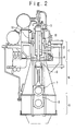
- the engine includes a cylinder 2, a piston 3 moving in the cylinder 2, a piston rod 4 connected to the piston 3, a crosshead 5 connected to the piston rod 4, a crankshaft 8, a connecting rod 7 connecting the crosshead 5 to the crankshaft 8, a jacket 1 in which the cylinder 2 is arranged, a bed 9 in which the crankshaft 8 is arranged, and a frame (engine frame) 6 arranged between the jacket 1 and the bed 9.
- a combustion space that is a space surrounded by the cylinder 2 and the piston 3
- a fuel is combusted.
- a translational motion of the piston 3 caused by the combustion is converted into a rotational motion of the crankshaft 8 via the connecting rod 7.
- the jacket 1, the frame 6, and the bed 9 are fastened to one another by tie-bolts 10.
- the frame 6 incudes a bulkhead 20, a top plate 23 arranged on a side adjacent to the jacket 1, a bottom plate 24 arranged on a side adjacent to the bed 9, and side plates 25.
- the bulkhead 20 includes a center plate 21 that forms a center portion of the bulkhead 20, interposing plates 22 that respectively form a camshaft-side portion and an exhaust-side portion of the bulkhead 20, and slide plates 31 arranged between the center plate 21 and the respective interposing plate 22. Positions of the camshaft-side portion and the exhaust-side portion of the bulkhead 20 correspond to positions of a camshaft-side and an exhaust-side of the engine, respectively.
- the slide plates 31 are located on both sides of the center plate 21 along a crosswise direction in Fig. 3 , respectively.
- the interposing plates 22 are located outside of both the slide plates 31, and side plates 25 are located outside of both the interposing plates 22, respectively.
- a longitudinal direction in Fig. 3 agrees with a moving direction (vertical direction) of the crosshead 5
- a depth direction in Fig. 3 agrees with a rotation axis direction of the crankshaft 8
- the crosswise direction in Fig. 3 is perpendicular to the moving direction of the crosshead 5 and the rotation axis direction of the crankshaft 8.
- Inner side surfaces of the slide plates 31 are welded to the center plate 21.
- Inner edges of the interposing plates 22 are welded to outer side surfaces of the slide plates 31. Inner side surfaces of the side plates 25 are welded to outer edges of the interposing plates 22. The outer edges of the interposing plates 22 are sides opposite to the slide plates 31.
- the top plate 23 is welded to upper sides of the slide plates 31, the interposing plates 22, and the side plates 25.
- the bottom plate 24 is welded to lower sides of the slide plates 31, the interposing plates 22, and the side plates 25.
- the slide plates 31 are provided along the vertical direction.
- the slide plates 31 guide the crosshead 5 to move along the vertical direction.
- Each slide plate 31 receives a side force from the crosshead 5.
- a direction of the side force is parallel to the crosswise direction in Fig. 3 .
- Thickness directions of the slide plates 31 are parallel to the crosswise direction in Fig. 3 .
- Thickness directions of the center plate 21 and the interposing plates 23 are parallel to the depth direction in Fig. 3 .
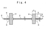
- Fig. 4 shows a horizontal sectional view of the bulkhead 20, taken along the line A-A in Fig. 3 .
- the tie-bolts 10 are arranged on both sides of each interposing plate 22, respectively.
- the center plate 21 and the interposing plates 22 are arranged on a center plane 51 of the bulkhead 20.
- a normal of the center plane S1 is parallel to the rotation axis direction of the crankshaft 8.
- Each of the center plate 21 and the interposing plates 22 is welded to the slide plate 31 such that the center plate 21 and the slide plate 31 are arranged in a T-shape and the interposing plate 22 and the slide plate 31 are arranged in a T-shape.
- Fig. 4 shows a horizontal sectional view of the bulkhead 20, taken along the line A-A in Fig. 3 .
- the tie-bolts 10 are arranged on both sides of each interposing plate 22, respectively.
- the center plate 21 and the interposing plates 22 are arranged on a center plane 51
- A denotes a thickness of each slide plate 31
- B denotes a thickness of each interposing plate 22
- C denotes a thickness of the center plate 21
- D denotes a distance from the center plane S1 to an end of each slide plate 31 measured along the normal of the center plane S1.
- Each slide plate 31 is symmetrically formed with respect to the center plane S1.
- each slide plate 31 is thick such that a ratio A/B of the thickness A of the slide plate 31 to the thickness B of the interposing plate 22 is equal to or larger than 1.5, rigidity of the frame 6 is ensured without reinforcements such as horizontal ribs. For example, there is no need to provide a reinforcement reinforcing the slide plate 31 from the interposing plate 22 and a reinforcement reinforcing the slide plate 31 from the side plate 25. Since the rigidity of the frame 6 is ensured, a moving locus of the crosshead 5 is stabilized. When no reinforcement is provided, the frame 6 has a simple shave and it is easy to manufacture and inspect the frame 6.
- each slide plate 31 is thick such that a ratio A/C of the thickness A of the slide plate 31 to the thickness C of the center plate 21 is equal to or larger than 1.5.
- the thickness A of the slide plate 31 is affected by design constraints, in general, the thickness A is smaller than a width (for example, 2D) of the slide plate 31.
- An engine according to a second embodiment of the present invention is configured similarly to the engine according to the first embodiment.
- a ratio D/A of the distance D from the center plane S1 to the end of the slide plate 31 to the thickness A of the slide plate 31 is equal to or smaller than 4.0.
- the side force acts on the end of the slide plate 31 or on a position of the slide plate 31 closer to the center plane S1 than the end. Accordingly, by setting the distance D small such that the ratio D/A is equal to or smaller than 4.0, a ratio of a distance between an action point of the side force and the center plane S1 to the thickness A of the slide plate 31 is small. Therefore, rigidity of the frame 6 is ensured without reinforcements such as horizontal ribs.
- the frame 6 has a simple shape and it is easy to manufacture and inspect the frame 6.
- the distance D from the center plate S1 to the end of the slide plate 31 is affected by design constrains, in general, the distance D is larger than a larger one of half the thickness C of the center plate 21 and half the thickness B of the interposing plate 22.
- An engine according to a third embodiment of the present invention is configured similarly to the engine according to the first embodiment.
- each interposing plate 22 since each interposing plate 22 is thick such that a ratio B/C of the thickness B of the interposing plate 22 to the thickness C of the center plate 21 is equal to or larger than 1.5, each interposing plate 22 reinforces the slide plate 31 against the side force. Consequently, rigidity of the frame 6 is ensured without reinforcements such as horizontal ribs. For example, there is no need to provide a reinforcement reinforcing the slide plate 31 from the interposing plate 22 and a reinforcement reinforcing the slide plate 31 from the side plate 25. When no reinforcement is provided, the frame 6 has a simple shape and it is easy to manufacture and inspect the frame 6.
- the thickness B of the interposing plate 22 is affected by design constrains, in general, the thickness B is smaller than the width (for example, 2D) of the slide plate 31.
- the center plate 21 and the slide plates 31 are integrally formed as a cast in each of the above embodiments
- the interposing plate 22 and the slide plate 31 are integrally formed as a cast in each of the above embodiments
- the center plate 21, the slide plates 31 and interposing plates 22 are integrally formed as a cast in each of the above embodiments
- all of the center plate 21, interposing plates 22, slide plates 31, the top plate 23, the bottom plate 24 and the side plates 25 are integrally formed as a cast in each of the above embodiments
- a wooden model for the cast is easily prepared, castability of the cast is improved, and the cast is easily inspected.
- the frame 6 is formed by welding the plates that are not formed as the cast to the cast, man-hour of welding and man-
- An engine according to a fourth embodiment of the present invention is configured similarly to the engine according to any one of the first to third embodiments except for points described below.
- reinforcements 40 reinforce one of the slide plate 31 on the camshaft-side and the slide plate 31 on the exhaust-side.
- the reinforcements 40 are provided to upper and lower portions of the slide plate 31.
- the reinforcements 40 are plate-shaped and thickness directions of the reinforcements 40 are parallel to the vertical direction.
- Fig. 6 shows a horizontal sectional view of the bulkhead 20, taken along the line B-B in Fig. 5 .
- the reinforcements 40 provided to the lower portion of the slide plate 31 are arranged on both sides of the center plane S1 of the bulkhead 20, respectively, and welded to the slide plate 31 and the interposing plate 22.
- the reinforcements 40 provided to the lower portion of the slide plate 31 are welded to the lower portion of the slide plate 31.
- the tie-bolt 10 penetrates through a space surrounded by the reinforcement 40, the slide plate 31, and the interposing plate 22.
- the reinforcements 40 provided to the upper portion of the slide plate 31 are configured similarly to the reinforcements 40 provided to the lower portion of the slide plate 31.
- a magnitude F of the side force received by the slide plate 31 from the crosshead 5 changes according to a motion of the crosshead 5 along the vertical direction (Z-axis direction).
- the magnitude F of the side force has a first local maximum value when the crosshead 5 is at a first position (Z1) and has a second local maximum value when the crosshead 5 is at a second position (Z2).
- the second position (Z2) is lower than the first position (Z1).
- the upper portion of the slide plate 31 receives the side force when the crosshead 5 is at the first position (Z1)
- the lower portion of the slide plate 31 receives the side force when the crosshead 5 is at the second position (Z2).
- the frame 6 since no reinforcement is provided to one of the slide plate 31 on the camshaft-side and the slide plate 31 on the exhaust-side, the frame 6 has a simple shape. Furthermore, as for the slide plate 31 to which the reinforcements 40 are provided, the reinforcements 40 are provided only to the upper and lower portions of the slide plate 31, so that the frame 6 has a simple shape. Therefore, man-hour of welding and man-hour of inspection for the frame 6 are reduced, and it is easy to manufacture and inspect the frame 6.
- the thickness A of the slide plate 31 to which the reinforcements 40 are provided can be thinner than the thicknesses A according to the first to third embodiments.
- the reinforcements 40 may be provided only to one of the upper and lower portions of the slide plate 31.
- the center plate 21 and the slide plates 31 are integrally formed as a cast in the present embodiment
- the interposing plate 22 and the slide plate 31 are integrally formed as a cast in the present embodiment
- the center plate 21, the slide plates 31 and interposing plates 22 are integrally formed as a cast in the present embodiment
- the center plate 21, interposing plates 22, slide plates 31, the top plate 23, the bottom plate 24 and the side plates 25 are integrally formed as a cast in the present embodiment
- all of the center plate 21, interposing plates 22, slide plates 31, the top plate 23, the bottom plate 24, the side plates 25 and the reinforcements 40 are formed as a cast in the present embodiment
- a portion of the center plate 21, interposing plates 22, slide plates 31, the top plate 23, the bottom plate 24, the side plates 25 and the reinforcements 40 are formed as a cast in the present embodiment
Landscapes
- Engineering & Computer Science (AREA)
- Chemical & Material Sciences (AREA)
- Combustion & Propulsion (AREA)
- Mechanical Engineering (AREA)
- General Engineering & Computer Science (AREA)
- Valve-Gear Or Valve Arrangements (AREA)
- Cylinder Crankcases Of Internal Combustion Engines (AREA)
- Connection Of Plates (AREA)
Abstract
An engine frame (6) includes: a first plate (21) forming a center portion of a bulkhead (20) ; a second plate (22) forming a camshaft-side portion or exhaust-side portion of the bulkhead (20); and a slide plate (31) arranged between the first plate (21) and the second plate (22). The slide plate (31) guides a crosshead (5). The first plate (21) and the second plate (22) are arranged on a plane (S1). The first plate (21) and the slide plate (31) are arranged in a T-shape.. The second plate (22) and the slide plate (31) are arranged in a T-shape. A ratio A/B of a thickness A of the slide plate (31) to a thickness B of the second plate (22) is equal to or larger than 1.5.
Description
- The present invention relates to a crosshead engine and particularly relates to a frame of a crosshead engine.
- Japanese Examined Utility Model Application Publication (
JU-Y-Heisei 06-48137 bulkhead 104 shown inFig. 1 . Thebulkhead 104 is integrally formed of cast steel by casting. Thebulkhead 104 includes acenter plate 101, guide bars (slide plates) 102, interposingplates 103,sidewalls 110, andhorizontal ribs 112.Bosses 111 are formed in the respectiveinterposing plates 103. Eachboss 111 includes a hole through which a tie-bolt (not shown) penetrates, - Japanese Laid Open Patent Application (
JP-P2001-289-114A JP-P2007-211786A 2977901 3226458 3538280 4005550 - An object of the present invention is to provide an engine frame easy to manufacture and inspect.
- In a first aspect of the present invention, an engine frame includes: a first plate forming a center portion of a bulkhead; a second plate forming a camshaft-side portion or exhaust-side portion of the bulkhead; and a slide plate arranged between the first plate and the second plate. The slide plate guides a crosshead. The first plate and the second plate are arranged on a plane. The first plate and the slide plate are arranged in aT-shape. The second plate and the slide plate are arranged in a T-shape: A ratio A/B of a thickness A of the slide plate to a thickness B of the second plate is equal to or larger than 1.5.
- Since the slide plate is thick such that the ratio A/B is equal to or larger than 1.5, rigidity of the engine frame is ensured without reinforcements such as horizontal ribs. When no reinforcement is provided, the engine frame has a simple shape and it is easy to manufacture and inspect the engine frame.
- In a second aspect of the present invention, an engine frame includes: a first plate forming a center portion of a bulkhead; a second plate forming a camshaft-side portion or exhaust-side portion of the bulkhead; and a slide plate arranged between the first plate and the second plate. The slide plate guides a crosshead. The first plate and the second plate are arranged on a plane. The first plate and the slide plate are arranged in a T-shape. The second plate and the slide plate are arranged in a T-shape. A ratio A/C of a thickness A of the slide plate to a thickness C of the first plate is equal to or larger than 1.5.
- Since the slide plate is thick such that the ratio A/C is equal to or larger than 1.5, rigidity of the engine frame is ensured without reinforcements such as horizontal ribs. When no reinforcement is provided, the engine frame has a simple shape and it is easy to manufacture and inspect the engine frame.
- In a third aspect of the present invention, an engine frame includes: a first plate forming a center portion of a bulkhead; a second plate forming a camshaft-side portion or exhaust-side portion of the bulkhead; and a slide plate arranged between the first plate and the second plate. The slide plate guides a crosshead. The first plate and the second plate are arranged on a plane. The first plate and the slide plate are arranged in a T-shape. The second plate and the slide plate are arranged in a T-shape. The slide plate is symmetrically formed with respect to the plane. A ratio D/A of a distance D from the plane to an end of the slide plate measured along a normal of the plane to a thickness A of the slide plate is equal to or smaller than 4.0.
- Since the distance D is small such that the ratio D/A is equal to or smaller than 4.0, a ratio of a distance between an action point of a side force acted from the crosshead on the slide plate and the plane to the thickness A of the slide plate is small. Therefore, rigidity of the engine frame is ensured without reinforcements such as horizontal ribs. When no reinforcement is provided, the engine frame has a simple shape and it is easy to manufacture and inspect the engine frame.
- In a fourth aspect of the present invention, an engine frame includes: a first plate forming a center portion of a bulkhead; a second plate forming a camshaft-side portion or exhaust-side portion of the bulkhead; and a slide plate arranged between the first plate and the second plate. The slide plate guides a crosshead. The first plate and the second plate are arranged on a plane. The first plate and the slide plate are arranged in a T-shape. The second plate and the slide plate are arranged in a T-shape. A ratio B/C of a thickness B of the second plate to a thickness C of the first plate is equal to or larger than 1.5.
- Since the second plate is thick such that the ratio B/C is equal to or larger than 1.5, the second plate reinforces the slide plate against a side force acted from the crosshead on the slide plate. Therefore, rigidity of the engine frame is ensured without reinforcements such as horizontal ribs. When no reinforcement is provided, the engine frame has a simple shape and it is easy to manufacture and inspect the engine frame.
- The slide plate guides the crosshead along a vertical direction. Preferably, a top plate is welded to an upper side of the slide plate, a bottom plate is welded to a lower side of the slide plate, and a side plate is welded to a side of the second plate. The side of the second plate is opposite to the first plate. Preferably, any reinforcement reinforcing the slide plate from the second plate or the side plate is not provided.
- Since there is no reinforcement reinforcing the slide plate from the second plate or the side plate, the engine frame has a simple shape and it is easy to manufacture and inspect the engine frame.
- Since the engine frame has a simple shape, man-hour of welding and man-hour of inspection are reduced in a case that the first plate and the second plate are respectively welded to the slide plate.
- Since the engine frame has a simple shape, in a case that the first plate and the slide plate are integrally formed as a cast and the second plate is welded to the slide plate, a wooden model for the cast is easily prepared, castability of the cast is improved, the cast is easily inspected, and man-hour of welding and man-hour of inspection for a welding between the side plate and the second plate are reduced.
- Since the engine frame has a simple shape, in a case that the second plate and the slide plate are integrally formed as a cast and the first plate is welded to the slide plate, a wooden model for the cast is easily prepared, castability of the cast is improved, the cast is easily inspected, and man-hour of welding and man-hour of inspection for a welding between the slide plate and the first plate are reduced.
- Since the engine frame has a simple shape, in a case that the first plate, the second plate and the slide plate are integrally formed as a cast, a wooden model for the cast is easily prepared, castability of the cast is improved, and the cast is easily inspected.
- The slide plate guides the crosshead along a vertical direction. Preferably, the engine frame further includes: a top plate welded to an upper side of the slide plate; a bottom plate welded to a lower side of the slide plate; and a side plate welded to a side of the second plate. The side of the second plate is opposite to the first plate. Since the engine frame has a simple shape, in a case that the first plate, the second plate, the slide plate, the top plate, the bottom plate and the side plate are integrally formed as a cast, a wooden model for the cast is easily prepared, castability of the cast is improved, and the cast is easily inspected.
- The slide plate guides the crosshead along a vertical direction. Preferably, the engine frame further includes: a top plate welded to an upper side of the slide plate; a bottom plate welded to a lower side of the slide plate; and a side plate welded to a side of the second plate. The side of the second plate is opposite to the first plate. Since the engine frame has a simple shape, in a case that a portion of the first plate, the second plate, the slide plate, the top plate, the bottom plate and the side plate are formed as a cast, a wooden model for the cast is easily prepared, castability of the cast is improved, and the cast is easily inspected. Since the shape of the engine frame is simple, in a case that the engine frame is formed by welding the plates that are not formed as the cast to the cast, man-hour of welding and man-hour of inspection are reduced.
- In a fifth aspect of the present invention, an engine includes: the above engine frame; a cylinder; a piston configured to move in the cylinder; a piston rod connected to the piston; the crosshead connected to the piston rod; a crankshaft; a connecting rod connecting the crosshead to the crankshaft; a jacket in which the cylinder is arranged; a bed in which the crankshaft is arranged; and a tie-bolt fastening the jacket, the engine frame and the bed.
- According to the present invention, an engine frame easy to manufacture and inspect is provided.
- The above and other objects, advantages and features of the present invention will be more apparent from the following description of certain embodiments taken in conjunction with the accompanying drawings, in which:
-
Fig. 1 is a horizontal sectional view of a conventional frame; -
Fig. 2 is a longitudinal sectional view of an engine according to a first embodiment of the present invention; -
Fig. 3 is a front view of a frame according to the first embodiment; -
Fig. 4 is a horizontal sectional view of the frame according to the first embodiment; -
Fig. 5 is a front view of a frame according to a fourth embodiment of the present invention; -
Fig. 6 is a horizontal sectional view of the frame according to the fourth embodiment; and -
Fig. 7 is a graph showing relationship between a position of a crosshead and a magnitude of a side force. - Hereinafter, an engine frame according to embodiments of the present invention will be described with reference to the attached drawings.
- Referring to
Fig. 2 , an engine according to a first embodiment of the present invention will be described. The engine includes acylinder 2, a piston 3 moving in thecylinder 2, apiston rod 4 connected to the piston 3, a crosshead 5 connected to thepiston rod 4, acrankshaft 8, a connectingrod 7 connecting the crosshead 5 to thecrankshaft 8, ajacket 1 in which thecylinder 2 is arranged, abed 9 in which thecrankshaft 8 is arranged, and a frame (engine frame) 6 arranged between thejacket 1 and thebed 9. In a combustion space that is a space surrounded by thecylinder 2 and the piston 3, a fuel is combusted. A translational motion of the piston 3 caused by the combustion is converted into a rotational motion of thecrankshaft 8 via the connectingrod 7. Thejacket 1, theframe 6, and thebed 9 are fastened to one another by tie-bolts 10. - As shown in
Fig. 3 , theframe 6 according to the present embodiment incudes abulkhead 20, atop plate 23 arranged on a side adjacent to thejacket 1, abottom plate 24 arranged on a side adjacent to thebed 9, andside plates 25. Thebulkhead 20 includes acenter plate 21 that forms a center portion of thebulkhead 20, interposingplates 22 that respectively form a camshaft-side portion and an exhaust-side portion of thebulkhead 20, andslide plates 31 arranged between thecenter plate 21 and therespective interposing plate 22. Positions of the camshaft-side portion and the exhaust-side portion of thebulkhead 20 correspond to positions of a camshaft-side and an exhaust-side of the engine, respectively. Theslide plates 31 are located on both sides of thecenter plate 21 along a crosswise direction inFig. 3 , respectively. The interposingplates 22 are located outside of both theslide plates 31, andside plates 25 are located outside of both the interposingplates 22, respectively. It is to be noted that a longitudinal direction inFig. 3 agrees with a moving direction (vertical direction) of the crosshead 5, a depth direction inFig. 3 agrees with a rotation axis direction of thecrankshaft 8, and that the crosswise direction inFig. 3 is perpendicular to the moving direction of the crosshead 5 and the rotation axis direction of thecrankshaft 8. Inner side surfaces of theslide plates 31 are welded to thecenter plate 21. Inner edges of the interposingplates 22 are welded to outer side surfaces of theslide plates 31. Inner side surfaces of theside plates 25 are welded to outer edges of the interposingplates 22. The outer edges of the interposingplates 22 are sides opposite to theslide plates 31. Thetop plate 23 is welded to upper sides of theslide plates 31, the interposingplates 22, and theside plates 25. Thebottom plate 24 is welded to lower sides of theslide plates 31, the interposingplates 22, and theside plates 25. - The
slide plates 31 are provided along the vertical direction. Theslide plates 31 guide the crosshead 5 to move along the vertical direction. Eachslide plate 31 receives a side force from the crosshead 5. A direction of the side force is parallel to the crosswise direction inFig. 3 . Thickness directions of theslide plates 31 are parallel to the crosswise direction inFig. 3 . Thickness directions of thecenter plate 21 and the interposingplates 23 are parallel to the depth direction inFig. 3 . -
Fig. 4 shows a horizontal sectional view of thebulkhead 20, taken along the line A-A inFig. 3 . The tie-bolts 10 are arranged on both sides of each interposingplate 22, respectively. Thecenter plate 21 and the interposingplates 22 are arranged on a center plane 51 of thebulkhead 20. A normal of the center plane S1 is parallel to the rotation axis direction of thecrankshaft 8. Each of thecenter plate 21 and the interposingplates 22 is welded to theslide plate 31 such that thecenter plate 21 and theslide plate 31 are arranged in a T-shape and the interposingplate 22 and theslide plate 31 are arranged in a T-shape. As shown inFig. 4 , A denotes a thickness of eachslide plate 31, B denotes a thickness of each interposingplate 22, C denotes a thickness of thecenter plate 21, and D denotes a distance from the center plane S1 to an end of eachslide plate 31 measured along the normal of the center plane S1. Eachslide plate 31 is symmetrically formed with respect to the center plane S1. - In the present embodiment, since each
slide plate 31 is thick such that a ratio A/B of the thickness A of theslide plate 31 to the thickness B of the interposingplate 22 is equal to or larger than 1.5, rigidity of theframe 6 is ensured without reinforcements such as horizontal ribs. For example, there is no need to provide a reinforcement reinforcing theslide plate 31 from the interposingplate 22 and a reinforcement reinforcing theslide plate 31 from theside plate 25. Since the rigidity of theframe 6 is ensured, a moving locus of the crosshead 5 is stabilized. When no reinforcement is provided, theframe 6 has a simple shave and it is easy to manufacture and inspect theframe 6. - Similar advantages can be attained when each
slide plate 31 is thick such that a ratio A/C of the thickness A of theslide plate 31 to the thickness C of thecenter plate 21 is equal to or larger than 1.5. - While the thickness A of the
slide plate 31 is affected by design constraints, in general, the thickness A is smaller than a width (for example, 2D) of theslide plate 31. - An engine according to a second embodiment of the present invention is configured similarly to the engine according to the first embodiment.
- In the present embodiment, a ratio D/A of the distance D from the center plane S1 to the end of the
slide plate 31 to the thickness A of theslide plate 31 is equal to or smaller than 4.0. The side force acts on the end of theslide plate 31 or on a position of theslide plate 31 closer to the center plane S1 than the end. Accordingly, by setting the distance D small such that the ratio D/A is equal to or smaller than 4.0, a ratio of a distance between an action point of the side force and the center plane S1 to the thickness A of theslide plate 31 is small. Therefore, rigidity of theframe 6 is ensured without reinforcements such as horizontal ribs. For example, there is no need to provide a reinforcement reinforcing theslide plate 31 from the interposingplate 22 and a reinforcement reinforcing theslide plate 31 from theside plate 25. When no reinforcement is provided, theframe 6 has a simple shape and it is easy to manufacture and inspect theframe 6. - While the distance D from the center plate S1 to the end of the
slide plate 31 is affected by design constrains, in general, the distance D is larger than a larger one of half the thickness C of thecenter plate 21 and half the thickness B of the interposingplate 22. - An engine according to a third embodiment of the present invention is configured similarly to the engine according to the first embodiment.
- In the present embodiment, since each interposing
plate 22 is thick such that a ratio B/C of the thickness B of the interposingplate 22 to the thickness C of thecenter plate 21 is equal to or larger than 1.5, each interposingplate 22 reinforces theslide plate 31 against the side force. Consequently, rigidity of theframe 6 is ensured without reinforcements such as horizontal ribs. For example, there is no need to provide a reinforcement reinforcing theslide plate 31 from the interposingplate 22 and a reinforcement reinforcing theslide plate 31 from theside plate 25. When no reinforcement is provided, theframe 6 has a simple shape and it is easy to manufacture and inspect theframe 6. - While the thickness B of the interposing
plate 22 is affected by design constrains, in general, the thickness B is smaller than the width (for example, 2D) of theslide plate 31. - Also in a case that the
center plate 21 and theslide plates 31 are integrally formed as a cast in each of the above embodiments, in a case that the interposingplate 22 and theslide plate 31 are integrally formed as a cast in each of the above embodiments, in a case that thecenter plate 21, theslide plates 31 and interposingplates 22 are integrally formed as a cast in each of the above embodiments, in a case that all of thecenter plate 21, interposingplates 22,slide plates 31, thetop plate 23, thebottom plate 24 and theside plates 25 are integrally formed as a cast in each of the above embodiments, and in a case that a portion of thecenter plate 21, interposingplates 22,slide plates 31, thetop plate 23, thebottom plate 24 and theside plates 25 are formed as a cast in each of the above embodiments, a wooden model for the cast is easily prepared, castability of the cast is improved, and the cast is easily inspected. In a case that theframe 6 is formed by welding the plates that are not formed as the cast to the cast, man-hour of welding and man-hour of inspection are reduced. - An engine according to a fourth embodiment of the present invention is configured similarly to the engine according to any one of the first to third embodiments except for points described below.
- Referring to
Fig. 5 , in thebulkhead 20 of theframe 6 according to the present embodiment,reinforcements 40 reinforce one of theslide plate 31 on the camshaft-side and theslide plate 31 on the exhaust-side. Thereinforcements 40 are provided to upper and lower portions of theslide plate 31. Thereinforcements 40 are plate-shaped and thickness directions of thereinforcements 40 are parallel to the vertical direction. -
Fig. 6 shows a horizontal sectional view of thebulkhead 20, taken along the line B-B inFig. 5 . Thereinforcements 40 provided to the lower portion of theslide plate 31 are arranged on both sides of the center plane S1 of thebulkhead 20, respectively, and welded to theslide plate 31 and the interposingplate 22. Thereinforcements 40 provided to the lower portion of theslide plate 31 are welded to the lower portion of theslide plate 31. The tie-bolt 10 penetrates through a space surrounded by thereinforcement 40, theslide plate 31, and the interposingplate 22. Thereinforcements 40 provided to the upper portion of theslide plate 31 are configured similarly to thereinforcements 40 provided to the lower portion of theslide plate 31. - Referring to
Fig. 7 , the upper and lower portions of theslide plate 31 to which thereinforcements 40 are provided will be described. As shown inFig. 7 , a magnitude F of the side force received by theslide plate 31 from the crosshead 5 changes according to a motion of the crosshead 5 along the vertical direction (Z-axis direction). The magnitude F of the side force has a first local maximum value when the crosshead 5 is at a first position (Z1) and has a second local maximum value when the crosshead 5 is at a second position (Z2). The second position (Z2) is lower than the first position (Z1). The upper portion of theslide plate 31 receives the side force when the crosshead 5 is at the first position (Z1), The lower portion of theslide plate 31 receives the side force when the crosshead 5 is at the second position (Z2). - According to the present embodiment, since no reinforcement is provided to one of the
slide plate 31 on the camshaft-side and theslide plate 31 on the exhaust-side, theframe 6 has a simple shape. Furthermore, as for theslide plate 31 to which thereinforcements 40 are provided, thereinforcements 40 are provided only to the upper and lower portions of theslide plate 31, so that theframe 6 has a simple shape. Therefore, man-hour of welding and man-hour of inspection for theframe 6 are reduced, and it is easy to manufacture and inspect theframe 6. - It is to be noted that the thickness A of the
slide plate 31 to which thereinforcements 40 are provided can be thinner than the thicknesses A according to the first to third embodiments. Thereinforcements 40 may be provided only to one of the upper and lower portions of theslide plate 31. - Also in a case that the
center plate 21 and theslide plates 31 are integrally formed as a cast in the present embodiment, in a case that the interposingplate 22 and theslide plate 31 are integrally formed as a cast in the present embodiment, in a case that thecenter plate 21, theslide plates 31 and interposingplates 22 are integrally formed as a cast in the present embodiment, in a case that thecenter plate 21, interposingplates 22,slide plates 31, thetop plate 23, thebottom plate 24 and theside plates 25 are integrally formed as a cast in the present embodiment, in a case that all of thecenter plate 21, interposingplates 22,slide plates 31, thetop plate 23, thebottom plate 24, theside plates 25 and thereinforcements 40 are formed as a cast in the present embodiment, and in a case that a portion of thecenter plate 21, interposingplates 22,slide plates 31, thetop plate 23, thebottom plate 24, theside plates 25 and thereinforcements 40 are formed as a cast in the present embodiment, castability of the cast is improved and the cast is easily inspected. In a case that theframe 6 is formed by welding the plates that are not formed as the cast to the cast, man-hour of welding and man-hour of inspection are reduced. - Although the present invention has been described above in connection with several embodiments thereof, it would be apparent from those skilled in the art that those embodiments are provided solely for illustrating the present invention, and should not be relied upon to construe the appended claims in a limiting sense.
Claims (14)
- An engine frame (6) comprising:a first plate (21) forming a center portion of a bulkhead (22);a second plate (22) forming a camshaft-side portion or exhaust-side portion of said bulkhead (20); anda slide plate (31) arranged between said first plate (21) and said second plate (22),wherein said slide plate (31) guides a crosshead (5),said first plate (21) and said second plate (22) are arranged on a plane (S1),said first plate (21) and said slide plate (31) are arranged in a T-shape,said second plate (22) and said slide plate (31) are arranged in a T-shape, anda ratio A/B of a thickness A of said slide plate (31) to a thickness B of said second plate (22) is equal to or larger than 1.5.
- The engine frame (6) according to claim 1, wherein said slide plate (31) guides said crosshead (5) along a vertical direction,
a top plate (23) is welded to an upper side of said slide plate (31),
a bottom plate (24) is welded to a lower side of said slide plate (31),
a side plate (25) is welded to a side of said second plate (22),
said side of said second plate (22) is opposite to said first plate (21), and
any reinforcement reinforcing said slide plate (31) from said second plate (22) or said side plate (25) is not provided. - The engine frame (6) according to claim 1 or 2, wherein said first plate (21) and said second plate (22) are respectively welded to said slide plate (31).
- The engine frame (6) according to claim 1 or 2, wherein said first plate (21) and said slide plate (31) are integrally formed as a cast, and
said second plate (22) is welded to said slide plate (31). - The engine frame (6) according to claim 1 or 2, wherein said second plate (22) and said slide plate (31) are integrally formed as a cast, and
said first plate (21) is welded to said slide plate (31). - The engine frame (6) according to claim 1 or 2, wherein said first plate (21), said secondplate (22) and said slide plate (31) are integrally formed as a cast.
- The engine frame (6) according to claim 1, further comprising:a top plate (23) welded to an upper side of said slide plate (31);a bottom plate (24) welded to a lower side of said slide plate (31); anda side plate (25) welded to a side of said second plate (22),wherein said slide plate (31) guides said crosshead (5) along a vertical direction,said side of said second plate (22) is opposite to said first plate (21), andsaid first plate (21), said second plate (22), said slide plate (31), said top plate (23), said bottom plate (24) and said side plate (25) are integrally formed as a cast.
- The engine frame (6) according to claim 1, further comprising:a top plate (23) welded to an upper side of said slide plate (31);a bottom plate (24) welded to a lower side of said slide plate (31); anda side plate (25) welded to a side of said second plate (22),wherein said slide plate (31) guides said crosshead (5) along a vertical direction,said side of said second plate (22) is opposite to said first plate (21), anda portion of said first plate (21), said second plate (22), said slide plate (31), said top plate (23), said bottom plate (24) and said side plate (25) are formed as a cast.
- The engine frame (6) according to any of claims 1 to 8, further comprising a reinforcement (40) provided to a portion of said slide plate (31),
wherein magnitude (F) of side force from said crosshead (5) has a local maximum value when said crosshead (5) is at a position (Z1, Z2), and
said portion of said slide plate (31) receives said side force when said crosshead (5) is at said position (Z1, Z2). - The engine frame (6) according to claim 9, wherein said reinforcement (40) is welded to said portion of said slide plate (31) and said second plate (22).
- An engine comprising:the engine frame (6) according to any of claims 1 to 10;a cylinder (2);a piston (3) configured to move in said cylinder (2);a piston rod (4) connected to said piston (3);said crosshead (5) connected to said piston rod (4);a crankshaft (8);a connecting rod (7) connecting said crosshead (5) to said crankshaft (8);a jacket (1) in which said cylinder (2) is arranged;a bed (9) in which said crankshaft (8) is arranged; anda tie-bolt (10) fastening said jacket (1), said engine frame (6) and said bed (9).
- An engine frame (6) comprising:a first plate (21) forming a center portion of a bulkhead (20);a second plate (22) forming a camshaft-side portion or exhaust-side portion of said bulkhead (20); anda slide plate (31) arranged between said first plate (21) and said second plate (22),wherein said slide plate (31) guides a crosshead (5),said first plate (21) and said second plate (22) are arranged on a plane (S1),said first plate (21) and said slide plate (31) are arranged in a T-shape,said second plate (22) and said slide plate (31) are arranged in a T-shape, anda ratio A/C of a thickness A of said slide plate (31) to a thickness C of said first plate (21) is equal to or larger than 1.5.
- An engine frame (6) comprising:a first plate (21) forming a center portion of a bulkhead (20);a second plate (22) forming a camshaft-side portion or exhaust-side portion of said bulkhead (20); anda slide plate (31) arranged between said first plate (21) and said second plate (22),wherein said slide plate (31) guides a crosshead (5),said first plate (21) and said second plate (22) are arranged on a plane (S1),said first plate (21) and said slide plate (31) are arranged in a T-shape,said second plate (22) and said slide plate (31) are arranged in a T-shape,said slide plate (31) is symmetrically formed with respect to said plane (S1), anda ratio D/A of a distance D from said plane (S1) to an end of said slide plate measured along a normal of said plane (S1) to a thickness A of said slide plate (31) is equal to or smaller than 4.0.
- An engine frame (6) comprising:a first plate (21) forming a center portion of a bulkhead (20);a second plate (22) forming a camshaft-side portion or exhaust-side portion of said bulkhead (20); anda slide plate (31) arranged between said first plate (21) and said second plate (22),wherein said slide plate (31) guides a crosshead (5),said first plate (21) and said second plate (22) are arranged on a plane (S1),said first plate (21) and said slide plate (31) are arranged in a T-shape,said second plate (22) and said slide plate (31) are arranged in a T-shape, anda ratio B/C of a thickness B of said second plate (22) to a thickness C of said first plate (21) is equal to or larger than 1.5.
Applications Claiming Priority (1)
| Application Number | Priority Date | Filing Date | Title |
|---|---|---|---|
| JP2009224072A JP2011074765A (en) | 2009-09-29 | 2009-09-29 | Engine frame |
Publications (1)
| Publication Number | Publication Date |
|---|---|
| EP2305990A1 true EP2305990A1 (en) | 2011-04-06 |
Family
ID=42167247
Family Applications (1)
| Application Number | Title | Priority Date | Filing Date |
|---|---|---|---|
| EP10001806A Withdrawn EP2305990A1 (en) | 2009-09-29 | 2010-02-23 | Engine frame |
Country Status (4)
| Country | Link |
|---|---|
| EP (1) | EP2305990A1 (en) |
| JP (1) | JP2011074765A (en) |
| KR (1) | KR101150106B1 (en) |
| CN (1) | CN102032245A (en) |
Families Citing this family (3)
| Publication number | Priority date | Publication date | Assignee | Title |
|---|---|---|---|---|
| JP6275611B2 (en) | 2014-09-26 | 2018-02-07 | 三菱重工業株式会社 | Guide plate, bulkhead unit, frame and crosshead internal combustion engine |
| JP6314075B2 (en) * | 2014-11-04 | 2018-04-18 | 三菱重工業株式会社 | Reinforcing member, bulkhead unit, frame, crosshead internal combustion engine |
| JP6675956B2 (en) * | 2016-08-29 | 2020-04-08 | 三菱重工業株式会社 | Frame and crosshead internal combustion engine |
Citations (7)
| Publication number | Priority date | Publication date | Assignee | Title |
|---|---|---|---|---|
| US1999350A (en) | 1929-08-03 | 1935-04-30 | Sulzer Ag | Frame for reciprocating engines |
| GB579846A (en) | 1941-05-31 | 1946-08-19 | Ove Petersen | Improvements in or relating to crossheads and crosshead guides of internal combustion engines |
| GB615201A (en) | 1945-08-11 | 1949-01-03 | Mark Ferdinand Meinertz | Improvements in and relating to frames for vertical piston engines |
| JPS52110312A (en) | 1976-03-13 | 1977-09-16 | Mitsubishi Heavy Ind Ltd | Engine frame for crosshead type internal-combustion engine |
| GB2006920A (en) | 1977-10-27 | 1979-05-10 | Sulzer Ag | Bearing Support for a Crosshead Slide of a Reciprocating Engine |
| EP2006523A1 (en) | 2007-06-18 | 2008-12-24 | Wärtsilä Schweiz AG | Large crosshead diesel motor |
| EP2236802A1 (en) | 2009-03-20 | 2010-10-06 | Wärtsilä Schweiz AG | Large crosshead diesel motor |
Family Cites Families (9)
| Publication number | Priority date | Publication date | Assignee | Title |
|---|---|---|---|---|
| JP2721667B2 (en) * | 1987-04-22 | 1998-03-04 | 三菱重工業株式会社 | Frame structure of crosshead type reciprocating internal combustion engine |
| JPH0648137Y2 (en) * | 1987-07-01 | 1994-12-07 | 三菱重工業株式会社 | Crosshead type internal combustion engine frame |
| AU5568594A (en) * | 1992-11-27 | 1994-06-22 | Bp Oil International Limited | Method of identifying liquid petroleum products |
| KR100223084B1 (en) * | 1993-09-14 | 1999-10-15 | 정몽규 | Cylinder block structure and integral engine block with integral ladder frame |
| JPH09209774A (en) * | 1996-01-30 | 1997-08-12 | Suzuki Motor Corp | Chain cover for internal combustion engine |
| JP3528616B2 (en) * | 1997-12-26 | 2004-05-17 | 豊田合成株式会社 | Weather strip |
| JP4005550B2 (en) * | 2003-10-10 | 2007-11-07 | エムエーエヌ・ディーゼル・エーエス | Engine frame structure |
| KR100530203B1 (en) * | 2003-10-10 | 2005-11-22 | 맨 비 앤드 더블유 디젤 에이/에스 | Engine frame construction |
| KR101361590B1 (en) * | 2006-07-18 | 2014-02-11 | 베르트질레 슈바이츠 악티엔게젤샤프트 | A hub holder for a shaft of a reciprocating piston engine |
-
2009
- 2009-09-29 JP JP2009224072A patent/JP2011074765A/en active Pending
-
2010
- 2010-02-23 KR KR1020100016155A patent/KR101150106B1/en active Active
- 2010-02-23 CN CN2010101200242A patent/CN102032245A/en active Pending
- 2010-02-23 EP EP10001806A patent/EP2305990A1/en not_active Withdrawn
Patent Citations (7)
| Publication number | Priority date | Publication date | Assignee | Title |
|---|---|---|---|---|
| US1999350A (en) | 1929-08-03 | 1935-04-30 | Sulzer Ag | Frame for reciprocating engines |
| GB579846A (en) | 1941-05-31 | 1946-08-19 | Ove Petersen | Improvements in or relating to crossheads and crosshead guides of internal combustion engines |
| GB615201A (en) | 1945-08-11 | 1949-01-03 | Mark Ferdinand Meinertz | Improvements in and relating to frames for vertical piston engines |
| JPS52110312A (en) | 1976-03-13 | 1977-09-16 | Mitsubishi Heavy Ind Ltd | Engine frame for crosshead type internal-combustion engine |
| GB2006920A (en) | 1977-10-27 | 1979-05-10 | Sulzer Ag | Bearing Support for a Crosshead Slide of a Reciprocating Engine |
| EP2006523A1 (en) | 2007-06-18 | 2008-12-24 | Wärtsilä Schweiz AG | Large crosshead diesel motor |
| EP2236802A1 (en) | 2009-03-20 | 2010-10-06 | Wärtsilä Schweiz AG | Large crosshead diesel motor |
Also Published As
| Publication number | Publication date |
|---|---|
| CN102032245A (en) | 2011-04-27 |
| KR20110035817A (en) | 2011-04-06 |
| KR101150106B1 (en) | 2012-06-14 |
| JP2011074765A (en) | 2011-04-14 |
Similar Documents
| Publication | Publication Date | Title |
|---|---|---|
| EP2825756B1 (en) | Engine piston | |
| CN101636577B (en) | Cylinder block | |
| CN103154538B (en) | Bearing cap and bearing cap complex | |
| EP2615316A1 (en) | Iron-based metal bearing cap cast into light-alloy member | |
| JP5811280B2 (en) | Actuator mounting structure for variable compression ratio internal combustion engine | |
| US7389763B2 (en) | Cylinder block integrated with crankcase | |
| GB2485542A (en) | Composite cylinder block of an internal combustion engine | |
| KR101150106B1 (en) | Engine frame | |
| US6324961B1 (en) | Oil passage arrangement in a piston | |
| JP5511302B2 (en) | Engine frame and manufacturing method thereof | |
| JP5932557B2 (en) | Internal combustion engine | |
| CN103038483B (en) | crosshead diesel engine crosshead | |
| JP4591482B2 (en) | Internal combustion engine | |
| JP5567230B1 (en) | Uniflow crosshead combustion engine | |
| JP5665498B2 (en) | Crosshead of crosshead type diesel engine | |
| US7273030B2 (en) | Crankshaft support structure of internal combustion engine | |
| JP4780145B2 (en) | Manufacturing method of casting suspension member | |
| JP4586035B2 (en) | Cylinder block of internal combustion engine and manufacturing method thereof | |
| JP6344150B2 (en) | Engine crankshaft bearing structure | |
| JP2007309271A (en) | Piston for internal combustion engine | |
| JP4506517B2 (en) | Engine V-type cylinder block | |
| JP7248463B2 (en) | Automotive internal combustion engine oil pan | |
| JP2008082248A (en) | Engine cylinder block | |
| JP2006348859A (en) | Cylinder block for internal combustion engine | |
| JP2006125446A (en) | Crank shaft |
Legal Events
| Date | Code | Title | Description |
|---|---|---|---|
| PUAI | Public reference made under article 153(3) epc to a published international application that has entered the european phase |
Free format text: ORIGINAL CODE: 0009012 |
|
| AK | Designated contracting states |
Kind code of ref document: A1 Designated state(s): AT BE BG CH CY CZ DE DK EE ES FI FR GB GR HR HU IE IS IT LI LT LU LV MC MK MT NL NO PL PT RO SE SI SK SM TR |
|
| AX | Request for extension of the european patent |
Extension state: AL BA RS |
|
| 17P | Request for examination filed |
Effective date: 20110922 |
|
| 17Q | First examination report despatched |
Effective date: 20120612 |
|
| STAA | Information on the status of an ep patent application or granted ep patent |
Free format text: STATUS: THE APPLICATION IS DEEMED TO BE WITHDRAWN |
|
| 18D | Application deemed to be withdrawn |
Effective date: 20121023 |