EP2305885A2 - Wartungsvorrichtung für den Schienenabstand von Eisenbahnen - Google Patents
Wartungsvorrichtung für den Schienenabstand von Eisenbahnen Download PDFInfo
- Publication number
- EP2305885A2 EP2305885A2 EP10176939A EP10176939A EP2305885A2 EP 2305885 A2 EP2305885 A2 EP 2305885A2 EP 10176939 A EP10176939 A EP 10176939A EP 10176939 A EP10176939 A EP 10176939A EP 2305885 A2 EP2305885 A2 EP 2305885A2
- Authority
- EP
- European Patent Office
- Prior art keywords
- piece
- locking
- faces
- bar
- mounting means
- Prior art date
- Legal status (The legal status is an assumption and is not a legal conclusion. Google has not performed a legal analysis and makes no representation as to the accuracy of the status listed.)
- Withdrawn
Links
- 230000003100 immobilizing effect Effects 0.000 claims abstract description 11
- 230000000903 blocking effect Effects 0.000 claims abstract description 8
- 229920002994 synthetic fiber Polymers 0.000 claims abstract description 6
- 238000000465 moulding Methods 0.000 claims description 2
- 239000002184 metal Substances 0.000 description 5
- 208000031968 Cadaver Diseases 0.000 description 4
- 239000012777 electrically insulating material Substances 0.000 description 3
- 238000004873 anchoring Methods 0.000 description 2
- 230000007547 defect Effects 0.000 description 2
- 238000010292 electrical insulation Methods 0.000 description 2
- 238000005242 forging Methods 0.000 description 2
- 238000003754 machining Methods 0.000 description 2
- 238000011084 recovery Methods 0.000 description 2
- 230000003014 reinforcing effect Effects 0.000 description 2
- 230000005489 elastic deformation Effects 0.000 description 1
- 239000011810 insulating material Substances 0.000 description 1
- 229920000642 polymer Polymers 0.000 description 1
Images


Classifications
-
- E—FIXED CONSTRUCTIONS
- E01—CONSTRUCTION OF ROADS, RAILWAYS, OR BRIDGES
- E01B—PERMANENT WAY; PERMANENT-WAY TOOLS; MACHINES FOR MAKING RAILWAYS OF ALL KINDS
- E01B5/00—Rails; Guard rails; Distance-keeping means for them
- E01B5/16—Distance keepers
Definitions
- the present invention relates to a device for maintaining the spacing of railway rails.
- Such a device is used to temporarily maintain the spacing of two rails of a railroad track when it has been found a defect in the anchoring of a rail. It comprises a bar of greater length than the spacing of the rails, two pieces mounted on this bar, support against the soles of the rails, or two pairs of such parts each forming a jaw engaged on both sides of the rails. the soleplate of a rail, and immobilizing members of the gripping parts relative to the bar, including nuts screwed on threaded portions of the bar. Since the rails are used for the routing of electrical signals, the parts of the contact pieces in contact with the rails are made of electrically insulating material, so that the resumption bars do not interfere with this path.
- bearing part comprising a body of synthetic material, which forms on a first side a housing for engaging the workpiece on one side of the sole of a rail, and a metal reinforcing plate, integral with the body on a second side, opposite to the first side.
- a bearing part comprising a body of synthetic material, which forms on a first side a housing for engaging the workpiece on one side of the sole of a rail, and a metal reinforcing plate, integral with the body on a second side, opposite to the first side.
- the bearing pieces of the existing resumption bars have the disadvantage of not completely satisfactory, not preventing the loosening of a clamping nut of a gripping piece.
- the present invention aims to remedy this disadvantage.
- bearing parts have an uncertain resistance over time given the large and repeated efforts they undergo during the passage of the trains (a recovery bar can be left in place for a relatively long time, the time the repair is scheduled and completed).
- the present invention also aims to remedy this drawback.
- the device concerned comprises, in a manner known per se, a bar of greater length than the spacing of the rails, two parts mounted on this bar, bearing against the soles of the rails, or two pairs of such pieces each forming a jaw engaged on both sides of the sole of a rail, and immobilizing members of the bearing grips relative to the bar.
- At least one bearing grip comprises first sliding mounting means of a locking piece of said immobilizing member with respect to said bar, this locking piece comprising second own sliding mounting means. engaging with said first sliding mounting means, and including a self-locking zone to engage said immobilizer; said first sliding mounting means and second sliding mounting means, when in engagement, allow sliding of the locking member between a non-locking position, wherein said locking area is not engaged with said member immobilizer, and a locking position, wherein said locking zone is engaged with said immobilizer.
- the device according to the invention thus makes it possible to prevent a play of said immobilizing member, in particular, when this immobilizing member is a nut, the loosening of this nut.
- the sliding assembly makes it easy to mount the locking piece on the support bearing piece and then to bring it, by simply sliding, in the locking position.
- said locking piece comprises at least one own latching part, in locking position of this part, to snap on the immobilizing member.
- said immobilizing member being a nut engaged on the bar
- said locking piece comprises two own latching parts, in locking position, to snap into two locations of the nut remote the one of the other, especially diametrically opposed.
- Said bearing piece thus has a metal body, which can be manufactured in one piece by machining or forging, and having a high strength, able to withstand the large and repeated efforts that the piece undergoes during the passage of trains.
- the sheath does not participate in the resistance of the support part and its sole function is to provide the necessary electrical insulation between this piece and the rail.
- the intermediate branch of the body advantageously has a width substantially equal to that of the tubular branch and is thus connected to this tubular branch by a zone extending substantially over half the circumference of this tubular branch.
- the connecting surface of the intermediate branch to the tubular branch is therefore very important, allowing the intermediate branch to be perfectly integral with the tubular branch.
- width it should be understood the dimension of the intermediate branch in the direction transverse to the axis of the conduit formed by the tubular branch.
- the intermediate branch can be connected to the tubular branch, on the side on which it extends relative to this intermediate branch, by a rounded wall.
- This rounded wall also has the function of increasing the connecting surface of the intermediate branch to the tubular branch.
- the other lateral branch of the body may have a width substantially equal to that of said intermediate branch, and / or on the side on which it extends relative to the intermediate branch. , be connected to this intermediate branch by a rounded wall.
- the tubular branch may comprise, on its side facing said other lateral branch, a flat part allowing a stable support against the sole of a rail.
- the sheath comprises walls forming a cavity and defining an opening, said body being intended to be engaged in said cavity by said opening; said walls are, when the body is fully engaged in the cavity, adapted to match all the faces of the body defining said housing and the faces of this body parallel to the axis of the duct defined by said tubular branch.
- An extended contact surface is thus obtained between the sheath and the body, ensuring an assembly of this sheath and this body.
- the insulating material constituting the sheath may have a high coefficient of friction, reinforcing this assembly, and / or the cavity delimited by the sheath may have dimensions slightly smaller than those of the body so as to generate a wedging of the body in the sheath when this body is completely engaged in this sheath.
- the figure 1 represents a device 1 for maintaining the rail gauge 100 of a railway track used to temporarily maintain the spacing of the two rails 100 when a defect in the anchoring of a rail has been noted.
- the device 1 comprises a bar 2 of greater length than the distance of the rails 100, two pairs of jaws 3 mounted on this bar 2, each of which is adapted to grip the base of a rail 100, each jaw 3 being formed of two 4 bearing parts against the sole of a rail 100, and nuts 5 for holding these parts 4 in the clamping position around these rail flanges.
- the bar 2 comprises threaded portions extending on either side of the zones of this bar that may be occupied by the parts 4, between the position shown in these parts 4, in which they clamp the flanges of the rails 100, and the disassembly position of the device 1, in which they are sufficiently spaced from each other to be removed from around the flanges of the rails 100.
- the nuts 5 are screwed on these threaded portions to maintain the parts 4 in the clamping position, and are connected to sleeves 6 to protect these threaded areas.
- the pieces 4 are all identical to each other, and the Figures 2 to 5 show one of them.
- the part 4 comprises a body 10 formed by a single piece and a sheath 11 adapted to be fitly engaged on the body 10.
- the latter is metal and is manufactured in one piece by machining or forging. It has a side view of a shape of "C" and thus delimits a housing 12 allowing the engagement of the part 4 on the sole of a rail 100.
- the lower lateral branch 10a of the body 10 is tubular and thus forms a duct 13 allowing the engagement of the workpiece 4 on the bar 2.
- the intermediate branch 10b of the body 10 has a width substantially equal to that of the tubular branch 10a and is thus connected to this branch continuously, by a zone extending substantially over half the circumference of this tubular branch.
- This intermediate branch 10b is also connected to the tubular branch 10a, on the side on which it extends relative to this intermediate branch, by a rounded wall 15 also having the function of increasing the connecting surface of the branch intermediate 10b to the tubular branch 10a.
- the upper branch 10c of the body 10 has a width substantially equal to that of said intermediate branch 10b, and on the side on which it extends relative to the intermediate branch 10b, is connected to this intermediate branch by a rounded wall 16.
- the sheath 11 is made of an electrically insulating material, in particular a synthetic material such as a polymer. It comprises walls 11a forming a cavity 20 fitted to the body 10, which define a lateral opening 21 for introducing this body into this cavity. As it appears on the figure 5 , the walls 11a are, when the body 10 is completely engaged in the cavity 20, adapted to match all the faces of the body defining the housing 12 and the faces of this body parallel to the axis of the conduit 13 delimited by the tubular branch 10a.
- the sheath 11 also comprises an opening 22 coming opposite the corresponding opening of the duct 13 when the body 10 is completely engaged in the cavity 20.
- ribs 23 forming a body with it, arranged on its walls 11a adapted to cover said body faces 10 parallel to the axis of the duct 13, these ribs 23 jointly forming a slideway parallel to the longitudinal direction of the intermediate branch 10b of the part 10.
- the ribs 23 thus constitute first sliding mounting means.
- FIGS. 6 and 7 show a blocking piece 25 fitted to each support part 4. It comprises upper parts 26 and lower 27 in the form of stirrups, integral with each other, the assembly being in one piece, in particular produced by molding a synthetic material. This synthetic material has a slight possibility of elastic deformation.
- the upper portion 26 includes two side walls 26a whose free ends comprise, on the faces of these walls 26a facing each other, parallel ribs 30. These walls 26a allow the engagement of the portion 26 on the piece 4, the ribs 30 being adapted to engage behind the ribs 23 and slide along them. These ribs 30 thus constitute second sliding mounting means.
- the central wall of the upper portion 26 has two angled faces, forming, with the portion 27, a hexagonal housing 32 adapted to receive the faceted reception of a nut 5, as described below.
- the lower portion 27 includes two side walls 27a whose free ends comprise, on the faces of these walls 27a facing each other, parallel ribs 31.
- the central wall of this lower portion 27 has two angled faces extending those of the central wall of the upper part 26, which form, with the faces of the walls 27a facing one another, four faces of said hexagonal housing 32.
- each locking piece 25 is put in place on a corresponding part 4 (cf. Figures 8 and 9 ), having descended along the intermediate branch thereof until engagement of the ribs 30 of this piece 5 behind the ribs 23 of the part 4.
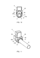
- the ribs 31 bear against the facets of the nut 5 and are elastically separated from each other by these (cf. figure 10 ).
- the sliding of the part 25 is continued until engagement of the nut 5 in the housing 32, in which position the ribs 31 of the walls 27a snap behind facets of the nut 5 (cf. figure 11 ). The piece 25 is thus kept locked in this position.
- the device 1 makes it possible, by means of each locking piece 25, to prevent loosening of the nut 5, and the sliding mounting of this piece 25 makes it possible to easily place the latter in place on the piece 4 and then bring it, by simple sliding, in the locking position.
- each bearing part 4 has a metal body 10 having a high strength, able to withstand the large and repeated efforts that the part 4 undergoes during the passage of trains.
- the sheath 11 does not participate in the resistance of the bearing part and has the only function to provide the necessary electrical insulation between this piece 4 and the rail 100.
- the invention thus provides a device 1 for maintaining the gauge of railway rails which overcomes the drawbacks of homologous devices of the prior art.
Landscapes
- Engineering & Computer Science (AREA)
- Mechanical Engineering (AREA)
- Architecture (AREA)
- Civil Engineering (AREA)
- Structural Engineering (AREA)
- Train Traffic Observation, Control, And Security (AREA)
- Braking Arrangements (AREA)
Applications Claiming Priority (1)
| Application Number | Priority Date | Filing Date | Title |
|---|---|---|---|
| FR0956486A FR2950370B1 (fr) | 2009-09-21 | 2009-09-21 | Dispositif de maintien de l'ecartement de rails de chemin de fer |
Publications (2)
| Publication Number | Publication Date |
|---|---|
| EP2305885A2 true EP2305885A2 (de) | 2011-04-06 |
| EP2305885A3 EP2305885A3 (de) | 2011-10-19 |
Family
ID=42124274
Family Applications (1)
| Application Number | Title | Priority Date | Filing Date |
|---|---|---|---|
| EP10176939A Withdrawn EP2305885A3 (de) | 2009-09-21 | 2010-09-15 | Wartungsvorrichtung für den Schienenabstand von Eisenbahnen |
Country Status (2)
| Country | Link |
|---|---|
| EP (1) | EP2305885A3 (de) |
| FR (1) | FR2950370B1 (de) |
Cited By (1)
| Publication number | Priority date | Publication date | Assignee | Title |
|---|---|---|---|---|
| JP2015193978A (ja) * | 2014-03-31 | 2015-11-05 | 株式会社レールテック | 分岐器トング位置調整具 |
Citations (2)
| Publication number | Priority date | Publication date | Assignee | Title |
|---|---|---|---|---|
| WO2008152578A1 (en) | 2007-06-13 | 2008-12-18 | Vape Rail International | Device for maintaining the spacing of railroad rails |
| FR2920790A1 (fr) | 2007-09-11 | 2009-03-13 | Vape Rail Internat Sa | Dispositif de maintien de l'ecartement de rails de chemin de fer |
-
2009
- 2009-09-21 FR FR0956486A patent/FR2950370B1/fr not_active Expired - Fee Related
-
2010
- 2010-09-15 EP EP10176939A patent/EP2305885A3/de not_active Withdrawn
Patent Citations (2)
| Publication number | Priority date | Publication date | Assignee | Title |
|---|---|---|---|---|
| WO2008152578A1 (en) | 2007-06-13 | 2008-12-18 | Vape Rail International | Device for maintaining the spacing of railroad rails |
| FR2920790A1 (fr) | 2007-09-11 | 2009-03-13 | Vape Rail Internat Sa | Dispositif de maintien de l'ecartement de rails de chemin de fer |
Cited By (1)
| Publication number | Priority date | Publication date | Assignee | Title |
|---|---|---|---|---|
| JP2015193978A (ja) * | 2014-03-31 | 2015-11-05 | 株式会社レールテック | 分岐器トング位置調整具 |
Also Published As
| Publication number | Publication date |
|---|---|
| EP2305885A3 (de) | 2011-10-19 |
| FR2950370B1 (fr) | 2011-09-02 |
| FR2950370A1 (fr) | 2011-03-25 |
Similar Documents
| Publication | Publication Date | Title |
|---|---|---|
| EP2648635B1 (de) | Vorrichtung zum spannen eines flexiblen bandes | |
| FR2742040A1 (fr) | Dispositif d'assemblage pour pieces allongees de materiel d'osteosynthese, notamment rachidienne | |
| FR2680461A1 (fr) | Implant pour dispositif d'osteosynthese notamment du rachis et dispositif correspondant pour sa mise en place. | |
| EP0894672A1 (de) | Lastenträger für Kraftfahrzeuge mit fester Dachreling | |
| EP2305885A2 (de) | Wartungsvorrichtung für den Schienenabstand von Eisenbahnen | |
| WO2007071668A1 (fr) | Dispositif de fixation et connexion centrale de balai d'essuie-glace | |
| FR2950369A1 (fr) | Dispositif de maintien de l'ecartement de rails de chemin de fer | |
| EP2762201B1 (de) | Mobile Verankerungsvorrichtung für Schiene | |
| EP1621237B1 (de) | Vorrichtung zum binden eines Schuhs auf einem Gleitbrett | |
| FR2920790A1 (fr) | Dispositif de maintien de l'ecartement de rails de chemin de fer | |
| CH686205A5 (fr) | Dispositif de support a l'epaule pour instrument a cordes. | |
| FR2982339A1 (fr) | Outil d'emboitement et de deboitement pour elements s'emboitant composant une tuyauterie | |
| FR2489140A1 (fr) | Compas de transfert de mesures anatomiques pour la realisation de protheses dentaires | |
| FR2581372A1 (fr) | Extenseur de courroie | |
| FR2849291A1 (fr) | Dispositif de raccordement electrique muni de porte-reperes pouvant immobiliser des reperes de tailles differentes | |
| EP1762279A1 (de) | Golfausrüstung mit Handwagen und Tasche | |
| FR2868031A1 (fr) | Entretoise a montage sans soudures pour berceau de support de train avant ou arriere d'un vehicule automobile | |
| FR2921703A3 (fr) | Dispositif anti-desserrage d'un ecrou de voie ferree | |
| EP0159250A1 (de) | Befestigungsvorrichtung für Gerüstkonsolen an Dachsparren und Befestigungseinheit für ihre Anwendung | |
| WO2016198770A1 (fr) | Ancillaire pour chirurgie ligamentaire de la cheville | |
| FR2600547A1 (fr) | Element d'adaptation pour la mise en oeuvre d'un gabarit pour ski traditionnel sur un monoski et procede utilisant de tels elements | |
| WO2019110888A1 (fr) | Dispositif amélioré de blocage de câbles de serrage de protections thermiques de divergents de moteurs spatiaux | |
| FR2934787A1 (fr) | Dispositif de fixation de securite pour un ski | |
| FR2898160A1 (fr) | Dispositif de fixation de deux pieces, l'une plaquee contre l'autre, au moyen d'une agrafe | |
| CH662149A5 (fr) | Element d'echafaudage a embout pour engagement d'un autre element avec percage des elements pour leur verrouillage. |
Legal Events
| Date | Code | Title | Description |
|---|---|---|---|
| PUAI | Public reference made under article 153(3) epc to a published international application that has entered the european phase |
Free format text: ORIGINAL CODE: 0009012 |
|
| AK | Designated contracting states |
Kind code of ref document: A2 Designated state(s): AL AT BE BG CH CY CZ DE DK EE ES FI FR GB GR HR HU IE IS IT LI LT LU LV MC MK MT NL NO PL PT RO SE SI SK SM TR |
|
| AX | Request for extension of the european patent |
Extension state: BA ME RS |
|
| PUAL | Search report despatched |
Free format text: ORIGINAL CODE: 0009013 |
|
| AK | Designated contracting states |
Kind code of ref document: A3 Designated state(s): AL AT BE BG CH CY CZ DE DK EE ES FI FR GB GR HR HU IE IS IT LI LT LU LV MC MK MT NL NO PL PT RO SE SI SK SM TR |
|
| AX | Request for extension of the european patent |
Extension state: BA ME RS |
|
| RIC1 | Information provided on ipc code assigned before grant |
Ipc: E01B 5/16 20060101AFI20110914BHEP |
|
| 17P | Request for examination filed |
Effective date: 20111114 |
|
| STAA | Information on the status of an ep patent application or granted ep patent |
Free format text: STATUS: THE APPLICATION IS DEEMED TO BE WITHDRAWN |
|
| 18D | Application deemed to be withdrawn |
Effective date: 20130403 |