EP2302816A1 - Wireless device - Google Patents
Wireless device Download PDFInfo
- Publication number
- EP2302816A1 EP2302816A1 EP09797856A EP09797856A EP2302816A1 EP 2302816 A1 EP2302816 A1 EP 2302816A1 EP 09797856 A EP09797856 A EP 09797856A EP 09797856 A EP09797856 A EP 09797856A EP 2302816 A1 EP2302816 A1 EP 2302816A1
- Authority
- EP
- European Patent Office
- Prior art keywords
- housing
- section
- antenna
- antenna element
- feeding section
- Prior art date
- Legal status (The legal status is an assumption and is not a legal conclusion. Google has not performed a legal analysis and makes no representation as to the accuracy of the status listed.)
- Withdrawn
Links
Images


Classifications
-
- H—ELECTRICITY
- H01—ELECTRIC ELEMENTS
- H01Q—ANTENNAS, i.e. RADIO AERIALS
- H01Q21/00—Antenna arrays or systems
- H01Q21/29—Combinations of different interacting antenna units for giving a desired directional characteristic
-
- H—ELECTRICITY
- H01—ELECTRIC ELEMENTS
- H01Q—ANTENNAS, i.e. RADIO AERIALS
- H01Q1/00—Details of, or arrangements associated with, antennas
- H01Q1/12—Supports; Mounting means
- H01Q1/22—Supports; Mounting means by structural association with other equipment or articles
- H01Q1/2258—Supports; Mounting means by structural association with other equipment or articles used with computer equipment
- H01Q1/2266—Supports; Mounting means by structural association with other equipment or articles used with computer equipment disposed inside the computer
-
- H—ELECTRICITY
- H01—ELECTRIC ELEMENTS
- H01Q—ANTENNAS, i.e. RADIO AERIALS
- H01Q1/00—Details of, or arrangements associated with, antennas
- H01Q1/12—Supports; Mounting means
- H01Q1/22—Supports; Mounting means by structural association with other equipment or articles
- H01Q1/24—Supports; Mounting means by structural association with other equipment or articles with receiving set
- H01Q1/241—Supports; Mounting means by structural association with other equipment or articles with receiving set used in mobile communications, e.g. GSM
- H01Q1/242—Supports; Mounting means by structural association with other equipment or articles with receiving set used in mobile communications, e.g. GSM specially adapted for hand-held use
- H01Q1/243—Supports; Mounting means by structural association with other equipment or articles with receiving set used in mobile communications, e.g. GSM specially adapted for hand-held use with built-in antennas
- H01Q1/244—Supports; Mounting means by structural association with other equipment or articles with receiving set used in mobile communications, e.g. GSM specially adapted for hand-held use with built-in antennas extendable from a housing along a given path
-
- H—ELECTRICITY
- H01—ELECTRIC ELEMENTS
- H01Q—ANTENNAS, i.e. RADIO AERIALS
- H01Q3/00—Arrangements for changing or varying the orientation or the shape of the directional pattern of the waves radiated from an antenna or antenna system
- H01Q3/24—Arrangements for changing or varying the orientation or the shape of the directional pattern of the waves radiated from an antenna or antenna system varying the orientation by switching energy from one active radiating element to another, e.g. for beam switching
-
- H—ELECTRICITY
- H01—ELECTRIC ELEMENTS
- H01Q—ANTENNAS, i.e. RADIO AERIALS
- H01Q9/00—Electrically-short antennas having dimensions not more than twice the operating wavelength and consisting of conductive active radiating elements
- H01Q9/04—Resonant antennas
- H01Q9/16—Resonant antennas with feed intermediate between the extremities of the antenna, e.g. centre-fed dipole
-
- H—ELECTRICITY
- H04—ELECTRIC COMMUNICATION TECHNIQUE
- H04B—TRANSMISSION
- H04B7/00—Radio transmission systems, i.e. using radiation field
- H04B7/02—Diversity systems; Multi-antenna system, i.e. transmission or reception using multiple antennas
- H04B7/04—Diversity systems; Multi-antenna system, i.e. transmission or reception using multiple antennas using two or more spaced independent antennas
- H04B7/06—Diversity systems; Multi-antenna system, i.e. transmission or reception using multiple antennas using two or more spaced independent antennas at the transmitting station
- H04B7/0686—Hybrid systems, i.e. switching and simultaneous transmission
- H04B7/0691—Hybrid systems, i.e. switching and simultaneous transmission using subgroups of transmit antennas
-
- H—ELECTRICITY
- H04—ELECTRIC COMMUNICATION TECHNIQUE
- H04B—TRANSMISSION
- H04B7/00—Radio transmission systems, i.e. using radiation field
- H04B7/02—Diversity systems; Multi-antenna system, i.e. transmission or reception using multiple antennas
- H04B7/04—Diversity systems; Multi-antenna system, i.e. transmission or reception using multiple antennas using two or more spaced independent antennas
- H04B7/08—Diversity systems; Multi-antenna system, i.e. transmission or reception using multiple antennas using two or more spaced independent antennas at the receiving station
- H04B7/0868—Hybrid systems, i.e. switching and combining
- H04B7/0874—Hybrid systems, i.e. switching and combining using subgroups of receive antennas
-
- H—ELECTRICITY
- H04—ELECTRIC COMMUNICATION TECHNIQUE
- H04M—TELEPHONIC COMMUNICATION
- H04M1/00—Substation equipment, e.g. for use by subscribers
- H04M1/02—Constructional features of telephone sets
- H04M1/0202—Portable telephone sets, e.g. cordless phones, mobile phones or bar type handsets
- H04M1/0206—Portable telephones comprising a plurality of mechanically joined movable body parts, e.g. hinged housings
- H04M1/0208—Portable telephones comprising a plurality of mechanically joined movable body parts, e.g. hinged housings characterized by the relative motions of the body parts
- H04M1/0214—Foldable telephones, i.e. with body parts pivoting to an open position around an axis parallel to the plane they define in closed position
- H04M1/0216—Foldable in one direction, i.e. using a one degree of freedom hinge
Definitions
- a foldable portable telephone described in Patent Document 1 proposes a technique in which, by supplying electric power to a shield case provided in at least one of the housings of the portable telephone, the housing is made to operate as an antenna so as to reduce gain change depending on the state of a user's hand holding the portable telephone. Further, a configuration in which a rod antenna is jointly used is also proposed.
- a rod antenna is provided in a lower case (housing), and the proximal end section (feeding section) of the rod antenna is connected to an output terminal of a transmission circuit.
- the shield box provided in the lower case (housing) is used as an antenna and the rod antenna is also used. This makes it possible to obtain a high gain and to reduce the gain change depending on the state of the hand of the user of the portable telephone.
- An object of the present invention is to provide a radio apparatus in which in the case where the radio apparatus includes two antenna elements that are respectively arranged at different housings and that are used in the same frequency band, the directivities of the two antennas are made substantially orthogonal to each other.
- a laterally long-shaped clamshell terminal which has a first and second housings each having a long-side direction length of about ⁇ /4 or shorter than ⁇ /4 of the use frequency, and which has a hinge section that connects the first housing to the second housing rotatably about the long-side direction of the housings, is featured by including: a first antenna element which is provided at the first housing; a second antenna element which is provided near one of the long-side direction ends in the second housing; a circuit board which has a ground pattern and which is provided in the second housing; and a first and second feeding sections which are connected to a radio circuit on the circuit board.
- a radio apparatus featured by including: a first housing; a first antenna element which is provided at the first housing; a second housing; a second antenna element which is provided at the second housing; a connecting section which connects the first housing and the second housing to each other; first and second circuit boards which are respectively provided in the first and second housings and each of which has a ground pattern; and first and second feeding sections which are connected to at least one radio circuit provided on at least one of the first and second circuit boards, and featured in that the first antenna element is electrically connected to the first feeding section via the connecting section, in that the long-side direction length of the first and second housings is about ⁇ /4 or shorter than ⁇ /4 of the use frequency of the first and second antennas, in that the second antenna element is provided at a long-side direction end section of the second housing, and in that the first antenna element and the second antenna element are used in the same frequency band. It is preferred that at least one of the first antenna element and the second antenna element, and the ground pattern on the circuit board can be
- a radio apparatus featured by including: a first housing; a first antenna element which is provided at the first housing; a second housing; a second antenna element which is provided at the second housing; a connecting section which connects a long side of the first housing to a long side of the second housing; a circuit board which is provided in the second housing and which has a ground pattern; a radio circuit which is provided in the circuit board; a first feeding section which is connected to the radio circuit and which supplies electric power to the first antenna element via the connecting section; and a second feeding section which is connected to the radio circuit and which supplies electric power to the second antenna element, and featured in that the long-side direction length of the first housing and the second housing is about ⁇ /4 or shorter than ⁇ /4 of the use frequency of the first antenna and the second antenna, in that the second antenna element is provided at a long-side direction end section of the second housing, and in that the first antenna element and the second antenna element are operated in the same frequency band.
- the second antenna element is electrically connected to the second feeding section and is extended in the direction substantially orthogonal to the direction of rotation of the hinge.
- the second antenna element may be a rod antenna which can be drawn out from the housing or which can be folded.
- 10 Portable telephone (radio apparatus), 11 ... First housing, 12 ... Second housing, 13a, 13b ... Hinge section, 14 ... Metal frame (conductive frame), 15 ... Display section, 16 ... Circuit board, 17 ... First feeding section, 18 ... Draw-out rod antenna, 19 ... Second feeding section, 20 ... Key section (input section), 21 ... Cellular antenna, 22 ... Flexible ground conductor, 22a ... Flexible cable, 23 ... Conductive hinge, 26 ... Impedance variable section, 28 ... Second built-in antenna, 34 ... Capacitive element.
- radio apparatuses according to respective embodiments of the present invention will be described with reference to the accompanying drawings. Note that in the following, a portable telephone will be described as an example of the radio apparatuses, but radio apparatuses, such as the other portable terminal and stationary radio apparatus, are also included in the scope of the present invention.
- FIG. 1 is a functional block diagram showing a configuration example of a portable telephone according to an embodiment of the present invention.
- a portable telephone 10 includes a radio communication section 238, a cellular antenna 21 for radio communication, a camera 112, a key input section 20, a display section 15, a loudspeaker 114, a microphone 124, a control section 231, a storage memory 232, a tuner 234, such as a one-segment tuner, and a housing antenna 14a and a rod antenna 18 which are used for the tuner 234.
- the portable telephone 10 may have the other functions. Note that reception signals from the housing antenna 14a and the rod antenna 18 are inputted into the tuner 234, but it is also possible to configure such that a selector switch SW 32 is provided to allow only one of the reception signals to be taken into the tuner 234.
- FIG. 2 is a schematic view showing an external configuration example of the portable telephone (radio apparatus) according to the first embodiment of the present invention.
- the portable telephone 10 is configured by connecting a first housing 11 to a second housing 12 by hinge sections 13a and 13b (connecting sections) which connect the housings 11 and 12 to each other rotatably about the housing long-side direction.
- a metal frame 14 (conductive frame: first antenna) is provided at the peripheral portion of the first housing 11, and the display section 15 is provided at the central portion of the first housing 11.
- a metal such as, for example, a magnesium alloy and SUS, which is highly conductive, light in weight, and high in mechanical strength, is used for the metal frame 14. By using such metal, it is possible that the mechanical strength is secured even in a thin shape, and that the metal frame 14 is arranged fully across the housing so as to operate as the first antenna element.
- a circuit board 16 to which a baseband circuit, a radio circuit, and the like, are mounted, and a first feeding section 17 which supplies electric power to the metal frame 14 are provided in the second housing 12.
- electric power is supplied by a second feeding section 19 to the draw-out rod antenna 18 which can be drawn out from or housed in the housing, and further the key section (input section) 20 which performs input operations of a telephone number, characters, and the like, is provided.
- the cellular antenna 21 which performs communication with a base station is also incorporated in the second housing 12.
- the rod antenna 18 is configured so as to be able to be drawn out in the direction substantially in parallel with the axis of rotation of the hinge.
- the ground in the first housing 11 and the ground of the circuit board 16 are connected to each other by a flexible ground conductor 22 via the hinge section 13b at the housing end side opposite to the first feeding section 17 and the second feeding section 19 in the direction of the X-axis (see Figure 2 ). That is, the first feeding section 17 and the second feeding section 19 are provided at the same end side in the second housing 12 in the extending direction of the hinge section 13a and the hinge section 13b, while the connection point of the ground of the circuit board 16 and the flexible ground conductor 22 is provided at the opposite side end.
- a flexible cable 22a in which various cables are bundled is provided along with the flexible ground conductor 22.
- the flexible cable 22a is a cable which electrically connects an electronic circuit (provided on a circuit board (not shown)) provided in the first housing 11 to an electronic circuit (usually provided on the circuit board 16) provided in the second housing 12. Note that the ground (ground pattern) is provided on substantially the whole rear surface of the circuit board 16.
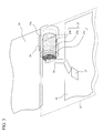
- FIG. 3 is a view showing an example of a method of connecting the first feeding section 17 to the metal frame 14.
- the metal frame 14 and the cylindrical hinge section 13a are formed into a shape integrally molded with a magnesium alloy.
- a conductive hinge 23 is incorporated in the cylindrical hinge section 13a.
- the conductive hinge 23 mainly has three sections each of which is partially or entirely made of a conductive metal, and which are a cylindrical conductive hinge main body section 23a, a conductive hinge section spring section 23b that is arranged at the outer periphery of the cylindrical conductive hinge main body section 23a so as to be in contact with the cylindrical hinge section 13a, and a conductive hinge projecting section 23c that is provided on the one side surface of the cylindrical conductive hinge main body section 23a.
- the inner wall of the hinge section 13a and the conductive hinge spring section 23b are brought into contact with each other by a suitable contact pressure, so as to be electrically conductive to each other.
- the conductive hinge projecting section 23c is connected with a suitable contact pressure to a spring-like sheet metal 24 provided between the conductive hinge projecting section 23c and the first feeding section 17, and is connected to the first feeding section 17 via the spring-like sheet metal 24.
- the first antenna element (metal frame 14) is DC connected by the spring-like sheet metal 24 via the second housing 12, the first feeding section 17, the spring-like sheet metal 24, and the conductive hinge 23 so as to be supplied with electric power.
- a capacitor structure of metal-insulator (or hollow body)-metal is formed on the outer peripheral side surface of the hinge section 13a so as to be brought into contact with the metal frame 14 of the first housing 11.
- the antenna characteristic can be adjusted by adopting such structure.
- the first feeding section 17 and the second feeding section 19 are connected to the tuner section 234 via a matching circuit (not shown).
- a matching circuit (not shown).
- an impedance circuit such as, for example, a filter, which is suitable for the use frequency band of the cellular antenna 21, is mounted in the matching circuit connected to the first feeding section 17.
- the present embodiment will be described by using, as an example, the case where the first antenna element 14 and the second antenna element 18 are used as antennas for receiving one-segment broadcasting in the same frequency band.
- the same frequency band means a frequency band having a fixed band width in which a plurality of channels used by the same communication system and method are collected.
- the frequency band for one-segment broadcasting which is currently used in Japan, is 470 MHz to 770 MHz.
- the wavelength ⁇ is about 638.3 mm at 470 MHz, and is about 389.6 mm at 770 MHz.
- one fourth of the wavelength ( ⁇ /4) is about 159.6 mm at 470 MHz, and is about 97.4 mm at 770 MHz.
- the housing length of a common clamshell portable telephone terminal in its longitudinal X direction is set to a value from 80 mm to at most about 120 mm, which value is very close to or slightly shorter than one fourth ( ⁇ /4) of the wavelength of the UHF band used in one-segment broadcasting.
- ⁇ /4 one fourth of the wavelength of the UHF band used in one-segment broadcasting.
- the housing length in the X direction is 120 mm and that the housing length in the Y direction is 50 mm.
- first antenna When electric power is supplied to the metal frame 14 from the first feeding section 17, current is made to flow mainly in the Y direction on the metal frame 14 and the ground of the circuit board 16, so that the metal frame 14 and the ground of the circuit board 16 operate as a dipole antenna (hereinafter described as "first antenna").
- the X-axis direction length and the Y-axis direction length of the circuit board 16 are compared with each other, the X-axis direction length is closer to ⁇ /4 of the use frequency.
- the rod antenna 18 is drawn out in the X direction, current is made to flow mainly in the X direction on the rod antenna 18 and the ground of the circuit board 16, so that the rod antenna 18 and the ground of the circuit board 16 operate as a dipole antenna (hereinafter described as "second antenna").
- Figure 4 is a view showing the directivity of the first antenna and the directivity of the second antenna.
- the current component flowing in the Y-axis direction on the metal frame 14 and the ground surface of the circuit board 16 acts as a dipole antenna, and hence the directivity of the first antenna is an 8-shaped directivity in which the Y-axis direction is set to null with respect to the horizontal plane.
- the current component flowing in the X-axis direction on the second antenna element 18 and the ground surface of the circuit board 16 acts as a dipole antenna, and hence the directivity of the second antenna is an 8-shaped directivity in which the X-axis direction is set to null with respect to the horizontal plane.
- the directivity of the first antenna is effective to reduce the amount of deterioration in the radio wave in the case where both the ends of the second housing 12 are held by hands, such as the case where browsing is performed using the terminal in the state in which the terminal is held substantially in parallel with the horizontal ground surface, because the amount of radio wave emitted in the direction of the human body present in the -Y-axis direction is small in such case.
- the housing length close to ⁇ /4 is most effective because the directivity becomes close to the 8-shaped directivity at the time when the housing length is set close to ⁇ /4.
- the antenna characteristics of the antennas are not substantially adversely affected by each other.
- the directivity of the first antenna and the directivity of the second antenna are added to each other, it is possible to obtain a high gain antenna characteristic which is substantially non-directional (nearly circular) with respect to the XY plane.
- the base stations which perform transmission by horizontally polarized waves, occupy the majority, and hence the above described directivity is very advantageous in the state of browsing at the terminal, or the like, in which state the XY plane of the terminal is held substantially in parallel with the horizontal ground surface.
- the metal frame 14 and the rod antenna 18 are described as antennas for receiving one-segment broadcasting, but the antennas are not limited to the antennas for receiving one-segment broadcasting.
- the antennas described in the first embodiment may be antennas for receiving other broadcasting, such as full-segment broadcasting, and may also be communication antennas which can be used for transmission or reception.
- the antenna is particularly effective at the time when the long-side (X-axis) direction length of the housing is close to one fourth of the wavelength ( ⁇ /4) of the use system or shorter than ⁇ /4.
- the rod antenna in which the second antenna element 18 can be drawn out from the second housing 12 in the X direction, is described as an example, but the drawing direction is not limited to this.
- the drawing direction is not limited to this.
- the second antenna element 18 can be drawn out in the Y-axis direction, when the second antenna element 18 is configured to be able to be folded in the X-axis direction, the same effect can be obtained.
- the configuration, in which the first feeding section 17 and the metal frame 14 are connected by the conductive hinge 23, is described.
- it may also be configured such that the first housing 11 and a metal arranged in the second housing 12 are overlapped with each other in a non-contact manner so that electric power is supplied by the capacitive coupling.
- the first antenna element is not limited to the metal frame, and electric power may be supplied to a shield case, or the like. Also, in the case where the first antenna element and the hinge section are not integrally molded, the same effect can be obtained.
- the rod antenna 18 may also be configured so as to be able to be supplied with electric power and drawn out at the opposite end.
- the first embodiment is described by using an example in which the antennas are used for diversity, or the like, in the same channel.
- the first embodiment may also be configured so as to perform two channel reception, or the like, by the separate channels in such a manner that the first antenna element and the second antenna element are respectively connected to separate tuners.
- the antennas may also be used as antennas for MIMO, and can also be used together with the methods of diversity, two channel reception, or the like.
- Figure 5 is a view showing a schematic configuration example of a portable telephone according to a second embodiment of the present invention. Note that in Figure 5 , portions identical with those in Figure 2 referred to and described in the first embodiment are denoted by the same reference numerals and characters, and the explanation of the portions is omitted.
- the rod antenna 18 is arranged in the second housing 12 and is configured to be able to be drawn out in the X-axis direction.
- the rod antenna 18 is configured such that a rod antenna tiltable section 18a is provided at the root section of the rod antenna 18, and such that the rod antenna 18 can be folded from the state of extending in the X-axis direction to the state of extending in the Y-axis direction by using the rod antenna tiltable section 18a as a base.
- the cellular antenna 21 is arranged at the opposite end of the second housing 12 in the X-axis direction so as to prevent that the cellular antenna 21 and the rod antenna 18 interfere with each other at the time when the rod antenna 18 is housed in the second housing 12.
- FIG 6 is a view showing a configuration around the hinge section 13b in Figure 5 .
- the flexible ground conductor 22 (along with which the flexible cable 22a is also provided as described above) is directly connected to the ground at the side of the first housing 11, and is made to pass through the inside of the hinge section 13b so as to be connected to the ground section of the circuit board 16 via an impedance variable section 26 configured by an impedance element.
- the impedance variable section 26 is configured such that the impedance thereof can be changed by impedance adjustment means, such as a filter, not only in the frequency band used by the first and second antennas but also in the frequency band used in the cellular frequency band.
- the second antenna element, and the current component which flows on the ground surface of the circuit board 16 in the X-axis direction of the ground surface act as a dipole antenna, and hence the directivity of the second antenna becomes an 8-shaped directivity in which the X-axis direction is set to null with respect to the XY plane.
- the directivity and polarization of the first antenna are respectively orthogonal to the directivity and polarization of the second antenna, so as to make it possible to obtain the same effect as in the case of the first embodiment, and also to make it possible to obtain excellent characteristics with respect to the cellular antenna 21. That is, the antenna characteristics of the cellular antenna 21 can be adjusted by adjusting the impedance variable section 26 to the frequency band used by the cellular antenna 21.
- the feeding points of the DTV antenna and the cellular antenna are separated in distance from each other, and hence there is little interference between the antennas.
- Figure 7 is a view showing a schematic configuration example of a portable telephone according to a third embodiment of the present invention. Note that also in Figure 7 , portions identical with those in Figure 2 referred to and described in the first embodiment are denoted by the same reference numerals and characters, and the explanation of the portions is omitted.
- the first feeding section 17 is arranged near the center of the second housing 12 in the X-axis direction thereof. Also in this case, since the metal frame 14, and the current component which flows on the ground surface of the circuit board 16 in the Y-axis direction of the ground surface, act as a dipole antenna, the directivity of the first antenna 21 becomes an 8-shaped directivity in which the Y-axis direction is set to null with respect to the XY plane. As a result, the directivity and polarization of the second antenna 18 are respectively orthogonal to the directivity and polarization of the first antenna, so as to make it possible to obtain the same effect.
- Figure 8 is a view showing a schematic configuration example of a portable telephone according to a fourth embodiment of the present invention. Note that also in Figure 8 , portions identical with those in Figure 2 referred to and described in the first embodiment are denoted by the same reference numerals and characters, and the explanation of the portions is omitted.
- the second feeding section 19 is connected to a second antenna element 28.
- the second antenna element 28 includes a conductor formed by a sheet metal, plating, or the like, and is incorporated in the second housing 12.
- the second antenna element 28, and the current component which flows on the ground surface of the circuit board 16 in the Y-axis direction of the ground surface act as a dipole antenna, and thereby the directivity of the second antenna becomes an 8-shaped directivity in which the Y-axis direction is set to null with respect to the XY plane.
- the directivity and polarization of the second antenna are orthogonal to each other, so as to make it possible to obtain the same effect.
- electric power is supplied to the second (built-in) antenna element 28 and the metal frame 14 at the same end side in the long-side direction of the housing, but electric power may be supplied to the second antenna element 28 at the opposite side end.
- the radio apparatus is configured such that in the state where the first housing and the second housing are opened, the directivities of the two antennas are orthogonal to each other on the surface formed by the housings. Therefore, a substantially non-directional antenna characteristic can be obtained in the horizontal plane at the time of browsing at the terminal when the XY plane of the radio apparatus is set substantially in parallel with the horizontal ground surface.
- the present embodiments have been described by using a portable telephone as an example, but it goes without saying that the present invention can be applied to electronic apparatuses, such as a personal computer, a PDA, and a PHS, each of which uses two antennas. Further, the above described embodiments are not limited to the configurations, and the like, shown in the accompanying drawings, but may be suitably changed within a range capable of exhibiting the effect of the present invention. In addition, the present invention can be practiced with proper modification without departing from the objects and the scope of the present invention.
- each section may be performed in such a manner that a program for realizing the functions described in the present embodiments is recorded in a computer readable recording medium, and that the program recorded in the recording medium is read and executed by a computer system.
- the "computer system” here is assumed to include an OS and hardware, such as peripheral apparatuses.
- the "computer system” is assumed to include a homepage providing environment (or display environment) in the case where the WWW system is used.
- the "computer readable recording medium” means portable media, such as a flexible disk, a magneto-optical disk, a ROM, and a CD-ROM, and also means a storage apparatus, such as a hard disk incorporated in the computer system.
- the "computer readable recording medium” is assumed to include a medium, such as a communication line, which in the case where a program is transmitted via a network, such as the Internet, or via a communication channel such as a telephone line, dynamically holds the program in a short period of time, and also to include a medium, such as a volatile memory in the computer system serving as a server or a client, which medium holds the program for a fixed period of time in such case where the program is transmitted.
- the above described program may be configured to realize a part of the above described functions, and further may also be configured to realize the above described functions in combination with a program already recorded in the computer system.
- the present invention can be used as a radio apparatus.
Abstract
Description
- In recent years, portable radio apparatuses have become widely used. In the portable radio apparatus, since importance has been attached to portability and since communication quality has also been required to be improved, the design of antenna elements has become important.
- A foldable portable telephone described in
Patent Document 1 as will be described below proposes a technique in which, by supplying electric power to a shield case provided in at least one of the housings of the portable telephone, the housing is made to operate as an antenna so as to reduce gain change depending on the state of a user's hand holding the portable telephone. Further, a configuration in which a rod antenna is jointly used is also proposed. For example, in the foldable (clamshell) portable telephone disclosed inPatent Document 1 as will be described below, a rod antenna is provided in a lower case (housing), and the proximal end section (feeding section) of the rod antenna is connected to an output terminal of a transmission circuit. In this technique, the shield box provided in the lower case (housing) is used as an antenna and the rod antenna is also used. This makes it possible to obtain a high gain and to reduce the gain change depending on the state of the hand of the user of the portable telephone. - Patent Document 1:
JP Patent No. 3830773 Figure 5 and Figure 13, and the related description in the specification) - However, in the conventional vertically openable clamshell terminal as disclosed in above described
Patent Document 1, there is a problem that when the antenna excited by supplying electric power to the shield case in one of the housings as well as the rod antenna having the feeding section at the long-side direction end section of the housing are both used at the same time, the currents are made to flow in the same direction through the ground conductor (ground layer housed in thelower case 34 in Patent Document 1) to be operated as a dipole antenna, and thereby the directivities of both the antennas are made similar to each other. - An object of the present invention is to provide a radio apparatus in which in the case where the radio apparatus includes two antenna elements that are respectively arranged at different housings and that are used in the same frequency band, the directivities of the two antennas are made substantially orthogonal to each other.
- In order to solve the above described problem, a laterally long-shaped clamshell terminal according to the present invention, which has a first and second housings each having a long-side direction length of about λ/4 or shorter than λ/4 of the use frequency, and which has a hinge section that connects the first housing to the second housing rotatably about the long-side direction of the housings, is featured by including: a first antenna element which is provided at the first housing; a second antenna element which is provided near one of the long-side direction ends in the second housing; a circuit board which has a ground pattern and which is provided in the second housing; and a first and second feeding sections which are connected to a radio circuit on the circuit board.
- According to the present invention, there is provided a radio apparatus featured by including: a first housing; a first antenna element which is provided at the first housing; a second housing; a second antenna element which is provided at the second housing; a connecting section which connects the first housing and the second housing to each other; first and second circuit boards which are respectively provided in the first and second housings and each of which has a ground pattern; and first and second feeding sections which are connected to at least one radio circuit provided on at least one of the first and second circuit boards, and featured in that the first antenna element is electrically connected to the first feeding section via the connecting section, in that the long-side direction length of the first and second housings is about λ/4 or shorter than λ/4 of the use frequency of the first and second antennas, in that the second antenna element is provided at a long-side direction end section of the second housing, and in that the first antenna element and the second antenna element are used in the same frequency band. It is preferred that at least one of the first antenna element and the second antenna element, and the ground pattern on the circuit board can be operated as a dipole antenna.
- Further, according to the present invention, there is provided a radio apparatus featured by including: a first housing; a first antenna element which is provided at the first housing; a second housing; a second antenna element which is provided at the second housing; a connecting section which connects a long side of the first housing to a long side of the second housing; a circuit board which is provided in the second housing and which has a ground pattern; a radio circuit which is provided in the circuit board; a first feeding section which is connected to the radio circuit and which supplies electric power to the first antenna element via the connecting section; and a second feeding section which is connected to the radio circuit and which supplies electric power to the second antenna element, and featured in that the long-side direction length of the first housing and the second housing is about λ/4 or shorter than λ/4 of the use frequency of the first antenna and the second antenna, in that the second antenna element is provided at a long-side direction end section of the second housing, and in that the first antenna element and the second antenna element are operated in the same frequency band.
- Note that when the use frequency is set as f, and when the velocity of light is set as c, λ can be obtained as λ = c/f. It is preferred that the second antenna element is electrically connected to the second feeding section and is extended in the direction substantially orthogonal to the direction of rotation of the hinge. The second antenna element may be a rod antenna which can be drawn out from the housing or which can be folded.
- According to the present invention configured as described above, in the state where the first housing and the second housing are opened, current components flowing through the ground conductors which respectively form dipole antennas in both the antennas are substantially orthogonal to each other, and hence the directivities of the two antennas are also substantially orthogonal to each other on the surface formed by both the housings. Therefore, a substantially non-directional antenna characteristic can be obtained in the horizontal plane at the time of browsing at the terminal when the XY plane of the terminal is set substantially in parallel with the horizontal ground surface. Therefore, even when the radio apparatus is directed in any direction, the radio apparatus can perform stable communication.
-
-
Figure 1 is a functional block diagram showing a configuration example of a portable telephone according to an embodiment of the present invention. -
Figure 2 is a schematic view showing an external configuration example of the portable telephone according to the first embodiment of the present invention. -
Figure 3 is a view showing an example of a method of connecting afirst feeding section 17 to ametal frame 14 inFigure 2 . -
Figure 4 is a view showing the directivity of a first antenna and the directivity of a second antenna. -
Figure 5 is a view showing a schematic configuration example of a portable telephone according to a second embodiment of the present invention. -
Figure 6 is a view showing a configuration around the hinge section inFigure 5 . -
Figure 7 is a view showing a schematic configuration example of a portable telephone according to a third embodiment of the present invention. -
Figure 8 is a view showing a schematic configuration example of a portable telephone according to a fourth embodiment of the present invention. - 10 ... Portable telephone (radio apparatus), 11 ... First housing, 12 ... Second housing, 13a, 13b ... Hinge section, 14 ... Metal frame (conductive frame), 15 ... Display section, 16 ... Circuit board, 17 ... First feeding section, 18 ... Draw-out rod antenna, 19 ... Second feeding section, 20 ... Key section (input section), 21 ... Cellular antenna, 22 ... Flexible ground conductor, 22a ... Flexible cable, 23 ... Conductive hinge, 26 ... Impedance variable section, 28 ... Second built-in antenna, 34 ... Capacitive element.
- In the following, radio apparatuses according to respective embodiments of the present invention will be described with reference to the accompanying drawings. Note that in the following, a portable telephone will be described as an example of the radio apparatuses, but radio apparatuses, such as the other portable terminal and stationary radio apparatus, are also included in the scope of the present invention.
-
Figure 1 is a functional block diagram showing a configuration example of a portable telephone according to an embodiment of the present invention. As shown inFigure 1 , aportable telephone 10 includes aradio communication section 238, acellular antenna 21 for radio communication, acamera 112, akey input section 20, adisplay section 15, aloudspeaker 114, amicrophone 124, acontrol section 231, astorage memory 232, atuner 234, such as a one-segment tuner, and ahousing antenna 14a and arod antenna 18 which are used for thetuner 234. Theportable telephone 10 may have the other functions. Note that reception signals from thehousing antenna 14a and therod antenna 18 are inputted into thetuner 234, but it is also possible to configure such that aselector switch SW 32 is provided to allow only one of the reception signals to be taken into thetuner 234. -
Figure 2 is a schematic view showing an external configuration example of the portable telephone (radio apparatus) according to the first embodiment of the present invention. As shown inFigure 2 , theportable telephone 10 is configured by connecting afirst housing 11 to asecond housing 12 byhinge sections housings first housing 11, and thedisplay section 15 is provided at the central portion of thefirst housing 11. A metal, such as, for example, a magnesium alloy and SUS, which is highly conductive, light in weight, and high in mechanical strength, is used for themetal frame 14. By using such metal, it is possible that the mechanical strength is secured even in a thin shape, and that themetal frame 14 is arranged fully across the housing so as to operate as the first antenna element. - On the other hand, a
circuit board 16 to which a baseband circuit, a radio circuit, and the like, are mounted, and afirst feeding section 17 which supplies electric power to themetal frame 14 are provided in thesecond housing 12. Further, in thesecond housing 12, electric power is supplied by asecond feeding section 19 to the draw-outrod antenna 18 which can be drawn out from or housed in the housing, and further the key section (input section) 20 which performs input operations of a telephone number, characters, and the like, is provided. Further, thecellular antenna 21 which performs communication with a base station is also incorporated in thesecond housing 12. Therod antenna 18 is configured so as to be able to be drawn out in the direction substantially in parallel with the axis of rotation of the hinge. - The ground in the
first housing 11 and the ground of thecircuit board 16 are connected to each other by aflexible ground conductor 22 via thehinge section 13b at the housing end side opposite to thefirst feeding section 17 and thesecond feeding section 19 in the direction of the X-axis (seeFigure 2 ). That is, thefirst feeding section 17 and thesecond feeding section 19 are provided at the same end side in thesecond housing 12 in the extending direction of thehinge section 13a and thehinge section 13b, while the connection point of the ground of thecircuit board 16 and theflexible ground conductor 22 is provided at the opposite side end. - A
flexible cable 22a in which various cables are bundled is provided along with theflexible ground conductor 22. Theflexible cable 22a is a cable which electrically connects an electronic circuit (provided on a circuit board (not shown)) provided in thefirst housing 11 to an electronic circuit (usually provided on the circuit board 16) provided in thesecond housing 12. Note that the ground (ground pattern) is provided on substantially the whole rear surface of thecircuit board 16. -
Figure 3 is a view showing an example of a method of connecting thefirst feeding section 17 to themetal frame 14. Themetal frame 14 and thecylindrical hinge section 13a are formed into a shape integrally molded with a magnesium alloy. Aconductive hinge 23 is incorporated in thecylindrical hinge section 13a. Theconductive hinge 23 mainly has three sections each of which is partially or entirely made of a conductive metal, and which are a cylindrical conductive hingemain body section 23a, a conductive hingesection spring section 23b that is arranged at the outer periphery of the cylindrical conductive hingemain body section 23a so as to be in contact with thecylindrical hinge section 13a, and a conductivehinge projecting section 23c that is provided on the one side surface of the cylindrical conductive hingemain body section 23a. As described above, the inner wall of thehinge section 13a and the conductivehinge spring section 23b are brought into contact with each other by a suitable contact pressure, so as to be electrically conductive to each other. The conductivehinge projecting section 23c is connected with a suitable contact pressure to a spring-like sheet metal 24 provided between the conductivehinge projecting section 23c and thefirst feeding section 17, and is connected to thefirst feeding section 17 via the spring-like sheet metal 24. The first antenna element (metal frame 14) is DC connected by the spring-like sheet metal 24 via thesecond housing 12, thefirst feeding section 17, the spring-like sheet metal 24, and theconductive hinge 23 so as to be supplied with electric power. - Note that it may also be configured such that, for example, a capacitor structure of metal-insulator (or hollow body)-metal is formed on the outer peripheral side surface of the
hinge section 13a so as to be brought into contact with themetal frame 14 of thefirst housing 11. The antenna characteristic can be adjusted by adopting such structure. - Further, on the
circuit board 16, thefirst feeding section 17 and thesecond feeding section 19 are connected to thetuner section 234 via a matching circuit (not shown). At this time, it is preferred that an impedance circuit such as, for example, a filter, which is suitable for the use frequency band of thecellular antenna 21, is mounted in the matching circuit connected to thefirst feeding section 17. - The present embodiment will be described by using, as an example, the case where the
first antenna element 14 and thesecond antenna element 18 are used as antennas for receiving one-segment broadcasting in the same frequency band. Here, the same frequency band means a frequency band having a fixed band width in which a plurality of channels used by the same communication system and method are collected. - The frequency band for one-segment broadcasting, which is currently used in Japan, is 470 MHz to 770 MHz. Thus, the wavelength λ is about 638.3 mm at 470 MHz, and is about 389.6 mm at 770 MHz. Further, one fourth of the wavelength (λ/4) is about 159.6 mm at 470 MHz, and is about 97.4 mm at 770 MHz.
- The housing length of a common clamshell portable telephone terminal in its longitudinal X direction is set to a value from 80 mm to at most about 120 mm, which value is very close to or slightly shorter than one fourth (λ/4) of the wavelength of the UHF band used in one-segment broadcasting. In the present embodiment, it is assumed, for example, that the housing length in the X direction is 120 mm and that the housing length in the Y direction is 50 mm.
- (1) When electric power is supplied to the
metal frame 14 from thefirst feeding section 17, current is made to flow mainly in the Y direction on themetal frame 14 and the ground of thecircuit board 16, so that themetal frame 14 and the ground of thecircuit board 16 operate as a dipole antenna (hereinafter described as "first antenna"). - (2) Further, when the X-axis direction length and the Y-axis direction length of the
circuit board 16 are compared with each other, the X-axis direction length is closer to λ/4 of the use frequency. Thus, when therod antenna 18 is drawn out in the X direction, current is made to flow mainly in the X direction on therod antenna 18 and the ground of thecircuit board 16, so that therod antenna 18 and the ground of thecircuit board 16 operate as a dipole antenna (hereinafter described as "second antenna"). - (3)
Figure 4 is a view showing the directivity of the first antenna and the directivity of the second antenna. The current component flowing in the Y-axis direction on themetal frame 14 and the ground surface of thecircuit board 16 acts as a dipole antenna, and hence the directivity of the first antenna is an 8-shaped directivity in which the Y-axis direction is set to null with respect to the horizontal plane. Further, the current component flowing in the X-axis direction on thesecond antenna element 18 and the ground surface of thecircuit board 16 acts as a dipole antenna, and hence the directivity of the second antenna is an 8-shaped directivity in which the X-axis direction is set to null with respect to the horizontal plane. - Therefore, the directivity of the first antenna is effective to reduce the amount of deterioration in the radio wave in the case where both the ends of the
second housing 12 are held by hands, such as the case where browsing is performed using the terminal in the state in which the terminal is held substantially in parallel with the horizontal ground surface, because the amount of radio wave emitted in the direction of the human body present in the -Y-axis direction is small in such case. - Note that the housing length close to λ/4 is most effective because the directivity becomes close to the 8-shaped directivity at the time when the housing length is set close to λ/4.
- Since the directivity of the first antenna and the directivity of the second antenna are orthogonal to each other, the antenna characteristics of the antennas are not substantially adversely affected by each other. When the directivity of the first antenna and the directivity of the second antenna are added to each other, it is possible to obtain a high gain antenna characteristic which is substantially non-directional (nearly circular) with respect to the XY plane. Thus, it is possible to obtain extremely excellent antenna characteristics in comparison with the time when the antennas are used, as a single antenna serving as a diversity antenna, in such a manner that the use of the antennas is switched by a switch.
- In the one-segment broadcasting in Japan, the base stations, which perform transmission by horizontally polarized waves, occupy the majority, and hence the above described directivity is very advantageous in the state of browsing at the terminal, or the like, in which state the XY plane of the terminal is held substantially in parallel with the horizontal ground surface.
- Note that in the first embodiment, the
metal frame 14 and therod antenna 18 are described as antennas for receiving one-segment broadcasting, but the antennas are not limited to the antennas for receiving one-segment broadcasting. The antennas described in the first embodiment may be antennas for receiving other broadcasting, such as full-segment broadcasting, and may also be communication antennas which can be used for transmission or reception. The antenna is particularly effective at the time when the long-side (X-axis) direction length of the housing is close to one fourth of the wavelength (λ/4) of the use system or shorter than λ/4. - Further, in the first embodiment, the rod antenna, in which the
second antenna element 18 can be drawn out from thesecond housing 12 in the X direction, is described as an example, but the drawing direction is not limited to this. For example, even in the case where thesecond antenna element 18 can be drawn out in the Y-axis direction, when thesecond antenna element 18 is configured to be able to be folded in the X-axis direction, the same effect can be obtained. - Further, in the first embodiment, the configuration, in which the
first feeding section 17 and themetal frame 14 are connected by theconductive hinge 23, is described. However, it may also be configured such that thefirst housing 11 and a metal arranged in thesecond housing 12 are overlapped with each other in a non-contact manner so that electric power is supplied by the capacitive coupling. Further, the first antenna element is not limited to the metal frame, and electric power may be supplied to a shield case, or the like. Also, in the case where the first antenna element and the hinge section are not integrally molded, the same effect can be obtained. - Further, electric power is supplied to the
metal frame 14 and therod antenna 18 at the same end side in the long-side direction of thesecond housing 12, but therod antenna 18 may also be configured so as to be able to be supplied with electric power and drawn out at the opposite end. - Further, the first embodiment is described by using an example in which the antennas are used for diversity, or the like, in the same channel. However, the first embodiment may also be configured so as to perform two channel reception, or the like, by the separate channels in such a manner that the first antenna element and the second antenna element are respectively connected to separate tuners. In this case, even when both the antennas are simultaneously used in the same frequency band, since the directivities of the antennas are orthogonal to each other, the coupling between both the antennas is small, and hence excellent antenna characteristics can be obtained in each of the antennas. Further, the antennas may also be used as antennas for MIMO, and can also be used together with the methods of diversity, two channel reception, or the like.
-
Figure 5 is a view showing a schematic configuration example of a portable telephone according to a second embodiment of the present invention. Note that inFigure 5 , portions identical with those inFigure 2 referred to and described in the first embodiment are denoted by the same reference numerals and characters, and the explanation of the portions is omitted. - In
Figure 5 , therod antenna 18 is arranged in thesecond housing 12 and is configured to be able to be drawn out in the X-axis direction. However, in this case, therod antenna 18 is configured such that a rodantenna tiltable section 18a is provided at the root section of therod antenna 18, and such that therod antenna 18 can be folded from the state of extending in the X-axis direction to the state of extending in the Y-axis direction by using the rodantenna tiltable section 18a as a base. Further, thecellular antenna 21 is arranged at the opposite end of thesecond housing 12 in the X-axis direction so as to prevent that thecellular antenna 21 and therod antenna 18 interfere with each other at the time when therod antenna 18 is housed in thesecond housing 12. -
Figure 6 is a view showing a configuration around thehinge section 13b inFigure 5 . The flexible ground conductor 22 (along with which theflexible cable 22a is also provided as described above) is directly connected to the ground at the side of thefirst housing 11, and is made to pass through the inside of thehinge section 13b so as to be connected to the ground section of thecircuit board 16 via animpedance variable section 26 configured by an impedance element. It is preferred that theimpedance variable section 26 is configured such that the impedance thereof can be changed by impedance adjustment means, such as a filter, not only in the frequency band used by the first and second antennas but also in the frequency band used in the cellular frequency band. - Also in this case, the second antenna element, and the current component which flows on the ground surface of the
circuit board 16 in the X-axis direction of the ground surface, act as a dipole antenna, and hence the directivity of the second antenna becomes an 8-shaped directivity in which the X-axis direction is set to null with respect to the XY plane. As a result, the directivity and polarization of the first antenna are respectively orthogonal to the directivity and polarization of the second antenna, so as to make it possible to obtain the same effect as in the case of the first embodiment, and also to make it possible to obtain excellent characteristics with respect to thecellular antenna 21. That is, the antenna characteristics of thecellular antenna 21 can be adjusted by adjusting theimpedance variable section 26 to the frequency band used by thecellular antenna 21. - Further, the feeding points of the DTV antenna and the cellular antenna are separated in distance from each other, and hence there is little interference between the antennas.
-
Figure 7 is a view showing a schematic configuration example of a portable telephone according to a third embodiment of the present invention. Note that also inFigure 7 , portions identical with those inFigure 2 referred to and described in the first embodiment are denoted by the same reference numerals and characters, and the explanation of the portions is omitted. - In
Figure 7 , thefirst feeding section 17 is arranged near the center of thesecond housing 12 in the X-axis direction thereof. Also in this case, since themetal frame 14, and the current component which flows on the ground surface of thecircuit board 16 in the Y-axis direction of the ground surface, act as a dipole antenna, the directivity of thefirst antenna 21 becomes an 8-shaped directivity in which the Y-axis direction is set to null with respect to the XY plane. As a result, the directivity and polarization of thesecond antenna 18 are respectively orthogonal to the directivity and polarization of the first antenna, so as to make it possible to obtain the same effect. -
Figure 8 is a view showing a schematic configuration example of a portable telephone according to a fourth embodiment of the present invention. Note that also inFigure 8 , portions identical with those inFigure 2 referred to and described in the first embodiment are denoted by the same reference numerals and characters, and the explanation of the portions is omitted. - In
Figure 8 , thesecond feeding section 19 is connected to asecond antenna element 28. Here, thesecond antenna element 28 includes a conductor formed by a sheet metal, plating, or the like, and is incorporated in thesecond housing 12. Also in this case, thesecond antenna element 28, and the current component which flows on the ground surface of thecircuit board 16 in the Y-axis direction of the ground surface, act as a dipole antenna, and thereby the directivity of the second antenna becomes an 8-shaped directivity in which the Y-axis direction is set to null with respect to the XY plane. Thus, the directivity and polarization of the second antenna are orthogonal to each other, so as to make it possible to obtain the same effect. - In the fourth embodiment, electric power is supplied to the second (built-in)
antenna element 28 and themetal frame 14 at the same end side in the long-side direction of the housing, but electric power may be supplied to thesecond antenna element 28 at the opposite side end. - As described above, the radio apparatus according to each of the embodiments of the present invention is configured such that in the state where the first housing and the second housing are opened, the directivities of the two antennas are orthogonal to each other on the surface formed by the housings. Therefore, a substantially non-directional antenna characteristic can be obtained in the horizontal plane at the time of browsing at the terminal when the XY plane of the radio apparatus is set substantially in parallel with the horizontal ground surface.
- Note that the present embodiments have been described by using a portable telephone as an example, but it goes without saying that the present invention can be applied to electronic apparatuses, such as a personal computer, a PDA, and a PHS, each of which uses two antennas. Further, the above described embodiments are not limited to the configurations, and the like, shown in the accompanying drawings, but may be suitably changed within a range capable of exhibiting the effect of the present invention. In addition, the present invention can be practiced with proper modification without departing from the objects and the scope of the present invention.
- Further, the processing of each section may be performed in such a manner that a program for realizing the functions described in the present embodiments is recorded in a computer readable recording medium, and that the program recorded in the recording medium is read and executed by a computer system. Note that the "computer system" here is assumed to include an OS and hardware, such as peripheral apparatuses.
- Further, the "computer system" is assumed to include a homepage providing environment (or display environment) in the case where the WWW system is used.
- Further, the "computer readable recording medium" means portable media, such as a flexible disk, a magneto-optical disk, a ROM, and a CD-ROM, and also means a storage apparatus, such as a hard disk incorporated in the computer system. Further, the "computer readable recording medium" is assumed to include a medium, such as a communication line, which in the case where a program is transmitted via a network, such as the Internet, or via a communication channel such as a telephone line, dynamically holds the program in a short period of time, and also to include a medium, such as a volatile memory in the computer system serving as a server or a client, which medium holds the program for a fixed period of time in such case where the program is transmitted. Further, the above described program may be configured to realize a part of the above described functions, and further may also be configured to realize the above described functions in combination with a program already recorded in the computer system.
- The present invention can be used as a radio apparatus.
Claims (10)
- A radio apparatus comprising:a first housing;a first antenna element which is provided at the first housing;a second housing;a second antenna element which is provided at the second housing;a connecting section which connects a long side of the first housing and a long side of the second housing to each other;a circuit board which is provided in the second housing and which has a ground pattern;a radio circuit which is provided in the circuit board;a first feeding section which is connected to the radio circuit and which supplies electric power to the first antenna element via the connecting section; anda second feeding section which is connected to the radio circuit and which supplies electric power to the second antenna element,wherein the long-side direction length of the first housing and the second housing is about λ/4 or shorter than λ/4 of the use frequency of the first antenna and the second antenna,wherein the second antenna element is provided at an end section of the second housing in the long-side direction of the second housing, andwherein the first antenna element and the second antenna element are operated in the same frequency band.
- The radio apparatus according to claim 1, wherein one of the first antenna element and the second antenna element, and the ground pattern on the circuit board can be operated as a dipole antenna.
- The radio apparatus according to claim 1 or 2, wherein the second antenna element can be extended in the direction substantially in parallel with the extending direction of the connecting section.
- The radio apparatus according to any one of claims 1 to 3, wherein the first feeding section and the second feeding section are arranged at the same end side in the second housing in the extending direction of the connecting section.
- The radio apparatus according to any one of claims 1 to 3, wherein the first feeding section is arranged near the center in the second housing in the extending direction of the connecting section.
- The radio apparatus according to any one of claims 1 to 5, wherein the first antenna element is supplied with electric power by being DC connected to the first feeding section.
- The radio apparatus according to any one of claims 1 to 5, wherein the first antenna element is connected to the first feeding section via capacitance.
- The radio apparatus according to any one of claims 1 to 7, further comprising a switch which switches the connecting destination of the radio circuit between the first antenna element and the second antenna element.
- The radio apparatus according to any one of claims 1 to 7, wherein the first antenna element and the second antenna element are used as diversity antennas.
- The radio apparatus according to any one of claims 1 to 9, wherein the first antenna element is a conductive frame which configures a part of one of the first housing and the second housing.
Applications Claiming Priority (2)
| Application Number | Priority Date | Filing Date | Title |
|---|---|---|---|
| JP2008183924 | 2008-07-15 | ||
| PCT/JP2009/062510 WO2010007931A1 (en) | 2008-07-15 | 2009-07-09 | Wireless device |
Publications (2)
| Publication Number | Publication Date |
|---|---|
| EP2302816A1 true EP2302816A1 (en) | 2011-03-30 |
| EP2302816A4 EP2302816A4 (en) | 2014-01-22 |
Family
ID=41550334
Family Applications (1)
| Application Number | Title | Priority Date | Filing Date |
|---|---|---|---|
| EP09797856.3A Withdrawn EP2302816A4 (en) | 2008-07-15 | 2009-07-09 | Wireless device |
Country Status (5)
| Country | Link |
|---|---|
| US (1) | US8253634B2 (en) |
| EP (1) | EP2302816A4 (en) |
| JP (1) | JP4660633B2 (en) |
| CN (1) | CN101809878B (en) |
| WO (1) | WO2010007931A1 (en) |
Families Citing this family (17)
| Publication number | Priority date | Publication date | Assignee | Title |
|---|---|---|---|---|
| CN101814649A (en) * | 2010-03-19 | 2010-08-25 | 中兴通讯股份有限公司 | Method for improving radiation performance of antenna and a mobile terminal |
| TW201214863A (en) * | 2010-09-17 | 2012-04-01 | Advanced Connectek Inc | Pivot antenna tuning circuit |
| CN102956953B (en) * | 2011-08-17 | 2015-07-29 | 联想(北京)有限公司 | Antenna assembly and terminal equipment |
| CN102956954B (en) * | 2011-08-17 | 2015-08-26 | 联想(北京)有限公司 | Antenna assembly and terminal equipment |
| CN102447757B (en) * | 2011-08-29 | 2014-07-16 | 惠州硕贝德无线科技股份有限公司 | Method for reducing influence of keypad of qwerty mobile phone on radiation performance of antenna |
| CN103066374B (en) * | 2011-10-24 | 2015-06-03 | 联想(北京)有限公司 | Gap structure antenna device and terminal unit |
| US9112271B2 (en) | 2011-10-09 | 2015-08-18 | Lenovo (Beijing) Co., Ltd. | Terminal device |
| TWI563724B (en) * | 2012-05-18 | 2016-12-21 | Compal Electronics Inc | Electronic device |
| US9203456B2 (en) | 2012-09-25 | 2015-12-01 | Htc Corporation | Mobile device |
| TWI528639B (en) * | 2012-10-09 | 2016-04-01 | 啟碁科技股份有限公司 | Antenna device and wireless communication device using the same |
| CN103311665B (en) * | 2013-06-09 | 2015-06-24 | 上海安费诺永亿通讯电子有限公司 | Antenna system applicable to mobile terminals with metal frame structures |
| JP5706479B2 (en) * | 2013-07-14 | 2015-04-22 | レノボ・シンガポール・プライベート・リミテッド | Antenna system mounted on portable computer and method for improving gain |
| CN104425884A (en) * | 2013-08-27 | 2015-03-18 | 中兴通讯股份有限公司 | Mobile terminal and antenna manufacturing method thereof |
| JP6271480B2 (en) * | 2015-08-26 | 2018-01-31 | 株式会社東芝 | Communication device, smart meter |
| US10141630B2 (en) * | 2017-04-01 | 2018-11-27 | Intel Corporation | Antenna incorporated into device hinge and method |
| EP3583657A4 (en) | 2017-04-13 | 2020-11-11 | Hewlett-Packard Development Company, L.P. | An antenna for an electronic device |
| KR102585017B1 (en) * | 2018-12-12 | 2023-10-05 | 삼성전자주식회사 | Antenna and electronic device having it |
Citations (3)
| Publication number | Priority date | Publication date | Assignee | Title |
|---|---|---|---|---|
| EP1538694A1 (en) * | 2002-07-19 | 2005-06-08 | Matsushita Electric Industrial Co., Ltd. | Portable wireless machine |
| WO2007138682A1 (en) * | 2006-05-30 | 2007-12-06 | Panasonic Corporation | Portable wireless unit |
| US20080143609A1 (en) * | 2004-12-10 | 2008-06-19 | Matsushita Electric Industrial Co., Ltd. | Foldable Portable Radio Device |
Family Cites Families (12)
| Publication number | Priority date | Publication date | Assignee | Title |
|---|---|---|---|---|
| JPH1198049A (en) * | 1997-09-16 | 1999-04-09 | Kokusai Electric Co Ltd | Portable radio equipment |
| US6658272B1 (en) * | 2000-04-28 | 2003-12-02 | Motorola, Inc. | Self configuring multiple element portable electronic device |
| JP3830773B2 (en) | 2001-05-08 | 2006-10-11 | 三菱電機株式会社 | Mobile phone |
| JP4517551B2 (en) | 2001-08-20 | 2010-08-04 | ソニー株式会社 | Portable information processing device |
| JP3613526B2 (en) * | 2003-01-24 | 2005-01-26 | 松下電器産業株式会社 | Portable radio |
| US8060167B2 (en) | 2002-07-19 | 2011-11-15 | Panasonic Corporation | Portable wireless machine |
| JP2005159391A (en) * | 2003-11-20 | 2005-06-16 | Matsushita Electric Ind Co Ltd | Opening/closing type mobile terminal instrument |
| US7787922B2 (en) | 2004-10-28 | 2010-08-31 | Panasonic Corporation | Portable telephone with broadcast receiver |
| JP4321588B2 (en) * | 2004-11-08 | 2009-08-26 | パナソニック株式会社 | Portable radio |
| WO2006112160A1 (en) * | 2005-03-30 | 2006-10-26 | Matsushita Electric Industrial Co., Ltd. | Foldable portable wireless device |
| JP4176756B2 (en) * | 2005-10-26 | 2008-11-05 | モレックス インコーポレーテッド | Electric wire support device |
| JP4724084B2 (en) * | 2006-09-28 | 2011-07-13 | 株式会社東芝 | Portable wireless device |
-
2009
- 2009-07-09 US US12/677,493 patent/US8253634B2/en not_active Expired - Fee Related
- 2009-07-09 CN CN2009801005813A patent/CN101809878B/en not_active Expired - Fee Related
- 2009-07-09 WO PCT/JP2009/062510 patent/WO2010007931A1/en active Application Filing
- 2009-07-09 JP JP2010501299A patent/JP4660633B2/en not_active Expired - Fee Related
- 2009-07-09 EP EP09797856.3A patent/EP2302816A4/en not_active Withdrawn
Patent Citations (3)
| Publication number | Priority date | Publication date | Assignee | Title |
|---|---|---|---|---|
| EP1538694A1 (en) * | 2002-07-19 | 2005-06-08 | Matsushita Electric Industrial Co., Ltd. | Portable wireless machine |
| US20080143609A1 (en) * | 2004-12-10 | 2008-06-19 | Matsushita Electric Industrial Co., Ltd. | Foldable Portable Radio Device |
| WO2007138682A1 (en) * | 2006-05-30 | 2007-12-06 | Panasonic Corporation | Portable wireless unit |
Non-Patent Citations (1)
| Title |
|---|
| See also references of WO2010007931A1 * |
Also Published As
| Publication number | Publication date |
|---|---|
| CN101809878B (en) | 2013-02-06 |
| US8253634B2 (en) | 2012-08-28 |
| JP4660633B2 (en) | 2011-03-30 |
| WO2010007931A1 (en) | 2010-01-21 |
| CN101809878A (en) | 2010-08-18 |
| JPWO2010007931A1 (en) | 2012-01-05 |
| EP2302816A4 (en) | 2014-01-22 |
| US20100328166A1 (en) | 2010-12-30 |
Similar Documents
| Publication | Publication Date | Title |
|---|---|---|
| US8253634B2 (en) | Radio apparatus | |
| CN109286076B (en) | Adjustable multiple-input multiple-output antenna structure | |
| US9596330B2 (en) | Antenna system with receiver diversity and tunable matching circuit | |
| CN104064877B (en) | There is the electronic equipment of the multi-port antenna structure with resonant slot | |
| JP3613525B2 (en) | Portable radio | |
| JP5412871B2 (en) | Antenna, radiation pattern switching method thereof, and wireless communication apparatus | |
| US7009567B2 (en) | Portable radio communication apparatus provided with a part of a housing operating as an antenna | |
| JP4199697B2 (en) | Portable radio | |
| JP4372158B2 (en) | Mobile phone with broadcast receiver | |
| CN106450689A (en) | Electronic Device Antenna With Isolation Mode | |
| US20100013720A1 (en) | Wireless communication apparatus with housing changing between open and closed states | |
| KR100832730B1 (en) | Antenna structure for devices with conductive chassis | |
| EP2266163B1 (en) | Antenna arrangement | |
| US20090069062A1 (en) | Mobile terminal | |
| US8884828B2 (en) | Mobile wireless terminal | |
| CN115458905A (en) | Antenna device and electronic apparatus | |
| JPWO2011135851A1 (en) | Wireless terminal | |
| US6392604B1 (en) | Antenna device comprising sliding connector means | |
| JP2006325152A (en) | Portable radio communication terminal device | |
| JP4641747B2 (en) | Mobile communication terminal | |
| WO2009153902A1 (en) | Portable wireless device | |
| JP5799247B2 (en) | Portable radio | |
| JP2006245870A (en) | Folding-type portable radio terminal | |
| JP2013201663A (en) | Portable radio terminal | |
| JP2010252308A (en) | Mobile electronic device |
Legal Events
| Date | Code | Title | Description |
|---|---|---|---|
| PUAI | Public reference made under article 153(3) epc to a published international application that has entered the european phase |
Free format text: ORIGINAL CODE: 0009012 |
|
| 17P | Request for examination filed |
Effective date: 20100311 |
|
| AK | Designated contracting states |
Kind code of ref document: A1 Designated state(s): AT BE BG CH CY CZ DE DK EE ES FI FR GB GR HR HU IE IS IT LI LT LU LV MC MK MT NL NO PL PT RO SE SI SK SM TR |
|
| AX | Request for extension of the european patent |
Extension state: AL BA RS |
|
| DAX | Request for extension of the european patent (deleted) | ||
| A4 | Supplementary search report drawn up and despatched |
Effective date: 20140107 |
|
| RIC1 | Information provided on ipc code assigned before grant |
Ipc: H01Q 21/29 20060101ALI20131219BHEP Ipc: H04B 1/38 20060101AFI20131219BHEP Ipc: H04M 1/02 20060101ALI20131219BHEP Ipc: H01Q 1/24 20060101ALI20131219BHEP Ipc: H01Q 3/24 20060101ALI20131219BHEP Ipc: H04B 7/08 20060101ALI20131219BHEP |
|
| STAA | Information on the status of an ep patent application or granted ep patent |
Free format text: STATUS: THE APPLICATION HAS BEEN WITHDRAWN |
|
| 18W | Application withdrawn |
Effective date: 20160418 |