JP2006325152A - Portable radio communication terminal device - Google Patents

Portable radio communication terminal device Download PDF

Info

Publication number
JP2006325152A
JP2006325152A JP2005148604A JP2005148604A JP2006325152A JP 2006325152 A JP2006325152 A JP 2006325152A JP 2005148604 A JP2005148604 A JP 2005148604A JP 2005148604 A JP2005148604 A JP 2005148604A JP 2006325152 A JP2006325152 A JP 2006325152A
Authority
JP
Japan
Prior art keywords
housing
antenna
mobile phone
terminal device
casing
Prior art date
Legal status (The legal status is an assumption and is not a legal conclusion. Google has not performed a legal analysis and makes no representation as to the accuracy of the status listed.)
Granted
Application number
JP2005148604A
Other languages
Japanese (ja)
Other versions
JP4626398B2 (en
Inventor
Jo Mizorogi
上 溝呂木
Kohei Mori
康平 森
Current Assignee (The listed assignees may be inaccurate. Google has not performed a legal analysis and makes no representation or warranty as to the accuracy of the list.)
Sony Corp
Original Assignee
Sony Corp
Priority date (The priority date is an assumption and is not a legal conclusion. Google has not performed a legal analysis and makes no representation as to the accuracy of the date listed.)
Filing date
Publication date
Application filed by Sony Corp filed Critical Sony Corp
Priority to JP2005148604A priority Critical patent/JP4626398B2/en
Publication of JP2006325152A publication Critical patent/JP2006325152A/en
Application granted granted Critical
Publication of JP4626398B2 publication Critical patent/JP4626398B2/en
Expired - Fee Related legal-status Critical Current
Anticipated expiration legal-status Critical

Links

Images

Abstract

<P>PROBLEM TO BE SOLVED: To obtain miniaturization with restrained degradation of an antenna characteristic when in use, and to obtain a good antenna characteristic even under a multipath fading environment. <P>SOLUTION: The portable radio communication terminal device includes a cabinet 2 in which a first cabinet 3 is combined with a second cabinet 4 via a hinge mechanism 5 in an arbitrarily expanding manner. To a conductor 7 and an antenna material 6 in the first cabinet 3, balanced power feed is performed from a radio transmission/reception circuit module 17 provided on the second cabinet 4, via a balanced and/or unbalanced conversion element 14, so as to configure a balanced antenna 8. The balanced and/or unbalanced conversion element 14 are connected to the radio transmission/reception circuit module 17 through a coaxial cable 13, and also, the first cabinet 3 and the second cabinet 4 are connected to the ground via the coaxial cable 13 independently of a signal line connection. <P>COPYRIGHT: (C)2007,JPO&INPIT

Description

本発明は、携帯電話機等の携帯型無線端末装置に関し、さらに詳しくは少なくとも第1筐体と第2筐体とに分割され、これら第1筐体と第2筐体とをヒンジ機構によって展開自在に結合した筐体を備える携帯型無線端末装置に関する。   The present invention relates to a portable wireless terminal device such as a cellular phone, and more specifically, is divided into at least a first casing and a second casing, and the first casing and the second casing can be unfolded by a hinge mechanism. The present invention relates to a portable wireless terminal device including a housing coupled to the.

携帯電話機等の携帯型無線端末装置には、高周波信号を送受信するアンテナとして、例えば筐体に設けられたロッドアンテナやヘリカルアンテナ或いは逆Fアンテナ等が備えられている。これらのアンテナは、不平衡アンテナであり、大きな面積のグランドを有することにより良好なアンテナ特性が発揮されるようになる。携帯型無線端末装置においては、一般に筐体地板によってグランドが構成されるが、大きなグランドを得るためには筐体が大型化する。また、携帯型無線端末装置においては、筐体を把持して使用されることから、人体の影響によって入力インピーダンスが大きく変化してアンテナ特性が劣化するといった問題がある。   A portable wireless terminal device such as a cellular phone is provided with, for example, a rod antenna, a helical antenna, an inverted F antenna, or the like provided in a housing as an antenna for transmitting and receiving a high-frequency signal. These antennas are unbalanced antennas, and a good antenna characteristic is exhibited by having a large area ground. In a portable wireless terminal device, a ground is generally constituted by a casing ground plane, but the casing is enlarged to obtain a large ground. Further, since the portable wireless terminal device is used by holding the housing, there is a problem that the input impedance is greatly changed due to the influence of the human body and the antenna characteristics are deteriorated.

平衡アンテナであるダイポールアンテナは、グランドが存在しなくともアンテナとして動作することが可能であることから、筐体地板の小型化に対して有効であるとともに地板に大きな電流を流さないために人体によるアンテナ特性の劣化に対して有効である。特許文献1には、携帯無線機器に内蔵された一対のヘリカルアンテナ素子に平衡給電することで、地板に流れる電流を抑制し、人体の影響によるアンテナ特性の劣化を低減するように構成したアンテナ装置が開示されている。   Since the dipole antenna, which is a balanced antenna, can operate as an antenna without a ground, it is effective for reducing the size of the chassis ground plane and does not cause a large current to flow through the ground plane. This is effective for deterioration of antenna characteristics. Patent Document 1 discloses an antenna device configured to suppress a current flowing in a ground plane and reduce deterioration of antenna characteristics due to the influence of a human body by performing balanced power feeding to a pair of helical antenna elements built in a portable wireless device. Is disclosed.

また、特許文献2には、第1導体板を設置した第1誘電体筐体と第2導体板を設置した第2誘電体筐体とを折り畳み自在に構成するとともに、第1導体板と第2導体板とに高周波電圧を平衡給電することでダイポールアンテナを構成した携帯無線機器が開示されている。携帯無線機器は、筐体以外に別途アンテナ素子を必要としないことから、小型化が図られるとともにエレメントの太さや幅により帯域特性が広がるダイポールアンテナの特性により周波数特性の広帯域化が図られるようになる。   Further, in Patent Document 2, a first dielectric casing provided with a first conductor plate and a second dielectric casing provided with a second conductor plate are configured to be foldable, and the first conductor plate and There has been disclosed a portable wireless device in which a dipole antenna is configured by balanced feeding of a high frequency voltage to a two-conductor plate. Since portable radio devices do not require a separate antenna element other than the housing, the size can be reduced, and the bandwidth characteristics can be broadened by the characteristics of the dipole antenna whose bandwidth characteristics are expanded by the thickness and width of the elements. Become.

特開2001−156517号公報JP 2001-156517 A 特開2004−208219号公報JP 2004-208219 A

上述した特許文献1に開示されたアンテナ装置においては、一対のヘリカルアンテナ素子が、地板に平行する方向にアンテナ軸を設定しかつ波長に比べて充分に小さな間隔を以って設置される。アンテナ装置においては、筐体を把持して使用される携帯無線機器に適用しても良好なアンテナ特性が保持されるといった特徴を有する。しかしながら、かかるアンテナ装置においては、アンテナ素子が一般に1/4波長系のアンテナの倍以上の長さが必要とされることから、小型化を要求される携帯無線機器に適用することが困難であるといった問題がある。   In the antenna device disclosed in Patent Document 1 described above, a pair of helical antenna elements are installed with an antenna axis set in a direction parallel to the ground plane and with a sufficiently small interval compared to the wavelength. The antenna device has a feature that good antenna characteristics are maintained even when applied to a portable wireless device used by holding a casing. However, in such an antenna device, since the antenna element generally requires a length that is at least twice that of a quarter wavelength antenna, it is difficult to apply it to a portable wireless device that is required to be downsized. There is a problem.

上述した特許文献2に開示されたアンテナ装置は、例えば携帯電話機の一般的な筐体構造として採用されている折り畳み型筐体にそのまま適用可能であり、アンテナ素子を不要とすることで機器の小型化が図られるようにする。しかしながら、かかるアンテナ装置は、アンテナ素子を構成する第2筐体を把持して使用されることが多いことから放射部を直接握ることになるため、人体の影響によりアンテナ特性が低下するといった問題がある。   The antenna device disclosed in Patent Document 2 described above can be applied as it is to, for example, a foldable housing employed as a general housing structure of a mobile phone, and can be reduced in size by eliminating the need for an antenna element. To make it easier. However, since such an antenna device is often used by gripping the second casing that constitutes the antenna element, it directly grips the radiating portion, and thus there is a problem that the antenna characteristics are deteriorated due to the influence of the human body. is there.

携帯電話機等の携帯型無線端末装置においては、使用者によって筐体を把持されるとともに頭部も近接する使用形態に対しても、良好なアンテナ特性が保持されるアンテナ装置が必要とされる。また、携帯型無線端末装置においては、小型化を実現するとともに様々な偏波が存在するマルチパスフェージング環境下において良好なアンテナ特性を発揮するアンテナ装置が必要とされる。   In a portable wireless terminal device such as a mobile phone, an antenna device is required that maintains good antenna characteristics even when the user grips the casing and the head is close to the usage. In addition, in the portable radio terminal device, an antenna device that realizes good antenna characteristics in a multipath fading environment that realizes miniaturization and various polarizations is required.

したがって、本発明は、使用時にもアンテナ特性の低下が抑制されて小型化が図られ、マルチパスフェージング環境下においてもアンテナ偏波を変化させることで良好なアンテナ特性を得る携帯型無線端末装置を提供することを目的とする。   Therefore, the present invention provides a portable wireless terminal device that can be reduced in size by suppressing deterioration of antenna characteristics even when in use, and obtains good antenna characteristics by changing antenna polarization even in a multipath fading environment. The purpose is to provide.

上述した目的を達成する本発明にかかる携帯型無線端末装置は、少なくとも第1筐体と第2筐体とに分割され、これら第1筐体と第2筐体とがヒンジ機構を介して展開自在に結合された筐体を備える。携帯型無線端末装置は、第1筐体の導体部によって第1アンテナエレメントを構成するとともに、第1筐体に対して展開自在に支持されたアンテナ部材によって第2アンテナエレメントを構成し、これら第1アンテナエレメントと第2アンテナエレメントに対して第2筐体側に設けた無線送受信回路部から平衡・不平衡変換素子を介して平衡給電を行うことによって平衡アンテナを構成する。携帯型無線端末装置は、第1筐体側に設けた平衡・不平衡変換素子と第2筐体側に設けた無線送受信回路部との給電線に同軸ケーブルを用いるとともに、この同軸ケーブルを介して第1筐体側の回路部と第2筐体側の回路部とが信号線路接続と独立したグランド接続が行われる。   The portable wireless terminal device according to the present invention that achieves the above-described object is divided into at least a first casing and a second casing, and the first casing and the second casing are deployed via a hinge mechanism. A housing that is freely coupled is provided. In the portable wireless terminal device, the first antenna element is configured by the conductor portion of the first casing, and the second antenna element is configured by the antenna member that is supported so as to be expandable with respect to the first casing. A balanced antenna is configured by performing balanced power feeding via a balanced / unbalanced conversion element from a wireless transmission / reception circuit unit provided on the second housing side with respect to one antenna element and a second antenna element. The portable wireless terminal device uses a coaxial cable as a power supply line between the balanced / unbalanced conversion element provided on the first housing side and the wireless transmission / reception circuit unit provided on the second housing side, and the first through the coaxial cable. The circuit unit on the first housing side and the circuit unit on the second housing side are connected to the ground independently of the signal line connection.

携帯型無線端末装置は、アンテナ部材として、例えばメアンダ(meander)型やヘリカル(herical)型等のモノポール系アンテナが用いられ、第1筐体に対して、ヒンジ機構を設けた第2筐体との結合部と対向する側に位置して或いはヒンジ機構を設けた第2筐体との結合部側に位置して部位に設けられる。携帯型無線端末装置は、アンテナ部材が、第1筐体に対して、適宜に展開した角度で保持されるようにして設けられる。   The portable wireless terminal device uses, for example, a meander-type or helical-type monopole antenna as an antenna member, and a second casing provided with a hinge mechanism with respect to the first casing. It is located on the side facing the coupling part with the second housing or provided on the part located on the coupling part side with the second housing provided with the hinge mechanism. The portable wireless terminal device is provided in such a manner that the antenna member is held at an appropriately expanded angle with respect to the first housing.

携帯型無線端末装置においては、第1アンテナエレメントと第2アンテナエレメントに対して第2筐体側に設けた無線送受信回路部から平衡・不平衡変換器を介して平衡給電を行うことによってダイポールアンテナを構成する。携帯型無線端末装置においては、各アンテナエレメントへの給電と第1筐体側の回路部及び第2筐体側の回路部とのグランドを接続する線路として同軸ケーブルを用いることにより、アンテナに起因する高周波のみが平衡給電形によって第2筐体グランドに漏れることは無くかつ第1筐体と第2筐体とを高周波的に接続する構成を可能とする。携帯型無線端末装置においては、各アンテナエレメントで受信した受信電波により励起した高周波電流が第1筐体から第2筐体に流入することを抑制するとともに、第1筐体と第2筐体との間において制御信号や各種の情報信号等の授受が行われるようにする。   In a portable wireless terminal device, a dipole antenna is mounted by performing balanced feeding via a balanced / unbalanced converter from a wireless transmission / reception circuit unit provided on the second housing side with respect to the first antenna element and the second antenna element. Constitute. In a portable wireless terminal device, a high frequency attributed to an antenna is obtained by using a coaxial cable as a line connecting a power supply to each antenna element and a ground between the circuit unit on the first housing side and the circuit unit on the second housing side. Only the balanced power supply type does not leak to the second housing ground, and the first housing and the second housing can be connected at a high frequency. In the portable wireless terminal device, the high frequency current excited by the received radio wave received by each antenna element is prevented from flowing from the first housing to the second housing, and the first housing and the second housing Control signals and various information signals are exchanged between the two.

携帯型無線端末装置においては、第2アンテナエレメントが第1筐体に対して展開自在に支持されたアンテナ部材によって構成されることで、アンテナ部材を適宜に展開して第1アンテナエレメントとにより多様な形態のダイポールアンテナを構成する。したがって、携帯型無線端末装置においては、垂直偏波と水平偏波とが混在するマルチパスフェージング環境下においてもアンテナ偏波を変化させることで良好なアンテナ特性を得る。   In the portable wireless terminal device, the second antenna element is configured by an antenna member that is supported so as to be expandable with respect to the first housing, and thus the antenna member is appropriately expanded to be various depending on the first antenna element. A dipole antenna of a different form is configured. Therefore, in the portable wireless terminal device, good antenna characteristics can be obtained by changing the antenna polarization even in a multipath fading environment in which vertical polarization and horizontal polarization are mixed.

本発明かかる携帯型無線端末装置によれば、第1筐体とアンテナ部材とによって平衡アンテナを構成することで、1/4λ(波長)系アンテナと同等の小型化が図られるようになる。携帯型無線端末装置によれば、第1筐体に対して使用者によりアンテナが受信する信号においては高周波的に隔離された第2筐体を把持して使用されるが、第2筐体を把持する人体の影響が遮断されてアンテナ特性の低下が抑制されて良好な無線通信を行うことが可能となる。また、携帯型無線端末装置によれば、多様な形態のダイポールアンテナを構成することでマルチパスフェージング環境下においても良好なアンテナ特性を得ることが可能とする。   According to the portable wireless terminal device of the present invention, a balanced antenna is formed by the first casing and the antenna member, thereby achieving a reduction in size equivalent to a 1 / 4λ (wavelength) antenna. According to the portable wireless terminal device, the signal received by the antenna by the user with respect to the first casing is used by gripping the second casing that is isolated in high frequency. The influence of the gripping human body is blocked, and the deterioration of the antenna characteristics is suppressed, so that favorable wireless communication can be performed. Also, according to the portable wireless terminal device, it is possible to obtain good antenna characteristics even in a multipath fading environment by configuring various forms of dipole antennas.

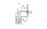
以下、本発明の実施の形態として図面に示した携帯電話機1について詳細に説明する。携帯電話機1は、図1及び図2に示すように筐体2が誘電素材によって形成された第1筐体3と第2筐体4とに分割され、ヒンジ機構5を介して展開自在に組み合わされて構成される。携帯電話機1は、ヒンジ機構5を介して第1筐体3に対して第2筐体4が折り畳んだ状態から、図3及び図4に示すように長さ方向に展開した状態や図5及び図6に示すように直交した状態に展開されて用いられる。   Hereinafter, a mobile phone 1 shown in the drawings as an embodiment of the present invention will be described in detail. As shown in FIGS. 1 and 2, the cellular phone 1 is divided into a first case 3 and a second case 4 in which the case 2 is formed of a dielectric material, and is combined in a freely deployable manner via a hinge mechanism 5. Configured. The cellular phone 1 has a state in which the second housing 4 is folded with respect to the first housing 3 via the hinge mechanism 5 and is unfolded in the length direction as shown in FIGS. 3 and 4. As shown in FIG. 6, it is used by being developed in an orthogonal state.

携帯電話機1は、第1筐体3側に一端部を展開自在に支持されてロッドアンテナ6が設けられる。携帯電話機1は、詳細を後述するようにロッドアンテナ6と第1筐体3に設けた導体部7に対して第2筐体4側から平衡給電を行うことによって構成されるダイポールアンテナ(平衡型アンテナ)8を備える。携帯電話機1は、ダイポールアンテナ8が一般的な携帯電話機に備えられる1/4λアンテナと同等の大きさによって構成されるとともに、第2筐体4を手持ち部として把持して使用される。   The mobile phone 1 is provided with a rod antenna 6 on one end of the mobile phone 1 that is supported on the side of the first housing 3 so as to be unfoldable. As will be described in detail later, the mobile phone 1 is a dipole antenna (balanced type) configured by performing balanced feeding from the second housing 4 side to the rod antenna 6 and the conductor portion 7 provided in the first housing 3. Antenna) 8. In the mobile phone 1, the dipole antenna 8 is configured to have a size equivalent to that of a ¼λ antenna provided in a general mobile phone, and is used by holding the second housing 4 as a handheld portion.

第1筐体3には、第1主面の略中央部に位置して液晶表示器9が配置されるとともに、ヒンジ機構5と対向する長手方向の他端近傍に位置してスピーカ10が配置されている。第1筐体3には、これら液晶表示器9やスピーカ10を実装するとともに図示しないこれらの駆動回路部等を設けた第1回路基板11が内蔵されている。第1回路基板11には、第2主面側に大きな面積を有する縦長矩形のグランドパターンを形成し、このグランドパターンによって上述した導体部7を構成するようにしてもよい。   In the first housing 3, a liquid crystal display 9 is disposed at a substantially central portion of the first main surface, and a speaker 10 is disposed in the vicinity of the other end in the longitudinal direction facing the hinge mechanism 5. Has been. The first housing 3 incorporates a first circuit board 11 on which the liquid crystal display 9 and the speaker 10 are mounted and these drive circuit units (not shown) are provided. The first circuit board 11 may be formed with a vertically long rectangular ground pattern having a large area on the second main surface side, and the above-described conductor portion 7 may be configured by this ground pattern.

第1筐体3には、第1回路基板11に、導体部7とロッドアンテナ6とに高周波電圧を平衡給電する高周波電源部12が設けられている。高周波電源部12には、第2筐体4側から不平衡線路の同軸ケーブル13を介して高周波電圧が供給される。高周波電源部12は、図2に示すように導体部7の長手方向の一端部と接続されるとともに相対するロッドアンテナ6の一端部と接続され、それぞれに高周波電圧を平衡給電する。第1筐体3には、平衡系と不平衡系との整合を図るためにバラン等の平衡不平衡変換素子14が第1回路基板11に設けられる。なお、第1筐体3には、例えばCCDカメラの撮像部等を設けるようにしてもよいことは勿論である。   The first housing 3 is provided with a high-frequency power supply unit 12 that balances and supplies a high-frequency voltage to the conductor unit 7 and the rod antenna 6 on the first circuit board 11. A high frequency voltage is supplied to the high frequency power supply unit 12 from the second housing 4 side via a coaxial cable 13 of an unbalanced line. As shown in FIG. 2, the high frequency power supply unit 12 is connected to one end portion of the conductor portion 7 in the longitudinal direction and is connected to one end portion of the opposing rod antenna 6, and supplies a high frequency voltage to each of them in a balanced manner. The first casing 3 is provided with a balanced / unbalanced conversion element 14 such as a balun on the first circuit board 11 in order to match the balanced system and the unbalanced system. Needless to say, the first housing 3 may be provided with an imaging unit of a CCD camera, for example.

第2筐体4には、第1主面側に適宜に配列された10キーや各種機能キー或いはジョグダイヤル等が設けられて操作部15が構成される。第2筐体4には、図2に示すように詳細を省略するが第2回路基板16が内蔵され、この第2回路基板16に無線送受信回路モジュール17や図示を省略する制御回路部や或いはダイヤル発信回路モジュールや電源回路等を構成するLSI素子やIC素子或いは各種の電子部品、さらには半導体メモリ等が実装される。   The second housing 4 is provided with 10 keys, various function keys, a jog dial, or the like appropriately arranged on the first main surface side to constitute an operation unit 15. As shown in FIG. 2, the second casing 4 includes a second circuit board 16 which is not shown in detail, and the second circuit board 16 includes a radio transmission / reception circuit module 17 and a control circuit unit not shown. An LSI element, an IC element, various electronic components, a semiconductor memory, and the like constituting a dial transmission circuit module, a power supply circuit, and the like are mounted.

第2筐体4には、第2回路基板16に実装されたマイクロホン18が、ヒンジ機構5と対向する長手方向の他端近傍に位置して配置される。第2筐体4には、図示しないが充電が可能な二次電池が内蔵されている。第2筐体4には、第2回路基板16に実装或いは接続される外部接続用コネクタや二次電池の充電用端子が、マイクロホン18を配置した端部側に位置して内蔵されている。   In the second housing 4, a microphone 18 mounted on the second circuit board 16 is disposed in the vicinity of the other end in the longitudinal direction facing the hinge mechanism 5. The second housing 4 includes a rechargeable secondary battery (not shown). In the second housing 4, an external connection connector mounted on or connected to the second circuit board 16 and a charging terminal for the secondary battery are built in and located on the end side where the microphone 18 is disposed.

ロッドアンテナ6は、第1筐体3に対してヒンジ機構5と対向する長手方向の他端近傍に位置し、基端部を支持部19によって回動自在に支持されて設けられる。ロッドアンテナ6は、所定の長さを有しており、アンテナエレメント20と、これを被覆する誘電体樹脂によって形成される被覆体21とによって構成される。アンテナエレメント20は、例えばメアンダ型やヘリカル型の導電性エレメントからなる。ロッドアンテナ6には、上述したように導体部7と対向するアンテナエレメント20の基端部に対して高周波電源部12から高周波電圧が印加される。   The rod antenna 6 is located in the vicinity of the other end in the longitudinal direction facing the hinge mechanism 5 with respect to the first housing 3, and the base end portion is rotatably supported by the support portion 19. The rod antenna 6 has a predetermined length, and is composed of an antenna element 20 and a covering 21 formed by a dielectric resin that covers the antenna element 20. The antenna element 20 is made of, for example, a meander type or helical type conductive element. As described above, a high frequency voltage is applied to the rod antenna 6 from the high frequency power supply unit 12 to the base end portion of the antenna element 20 facing the conductor portion 7.

支持部19は、詳細を省略するが第1筐体3に設けた回転支軸やクリック機構等を有しており、ロッドアンテナ6の基端部に設けた軸受け部を回動自在に支持する。携帯電話機1は、未使用状態において、支持部19によってロッドアンテナ6を第1筐体3の背面側に設けた図示しない収納凹部内に全長に亘って収納した状態で保持するようにして携帯性に支障が無いようにする。支持部19は、携帯電話機1を使用する際にロッドアンテナ6が図1矢印で示すように側方側へと回動操作されるようにして第1筐体3から突出された状態とする。支持部19は、クリック機構によって、ロッドアンテナ6を支持部19に対して任意の回動位置で保持する。   Although not described in detail, the support portion 19 has a rotation support shaft, a click mechanism, and the like provided in the first housing 3, and rotatably supports a bearing portion provided at the base end portion of the rod antenna 6. . The mobile phone 1 is portable so that the rod antenna 6 is held in the storage recess (not shown) provided on the back side of the first housing 3 by the support portion 19 in the unused state. So that there is no problem. The support unit 19 protrudes from the first housing 3 so that the rod antenna 6 is rotated to the side as shown by an arrow in FIG. 1 when the mobile phone 1 is used. The support part 19 holds the rod antenna 6 at an arbitrary rotation position with respect to the support part 19 by a click mechanism.

携帯電話機1は、ヒンジ機構5を跨って設けられたフレキシブル回路基板22によって上述した第1筐体3側の第1回路基板11と第2筐体4側の第2回路基板16との電気的接続が行われる。フレキシブル回路基板22は、第1筐体3側から第2筐体4側の各部に対して電源や制御信号或いは音声信号等が供給されるようにする。フレキシブル回路基板22には、従来の携帯電話機に設けられたフレキシブル回路基板のように第1回路基板11と第2回路基板16との間のグランド接続を行うためのパターンが設けられていない。したがって、フレキシブル回路基板22においては、第1筐体3と第2筐体4とを電源や各信号等の伝送部位においてグランドを切り離した構造の携帯電話機1を構成する。   The cellular phone 1 is electrically connected to the first circuit board 11 on the first housing 3 side and the second circuit board 16 on the second housing 4 side described above by the flexible circuit board 22 provided across the hinge mechanism 5. A connection is made. The flexible circuit board 22 is configured such that a power source, a control signal, an audio signal, or the like is supplied from the first housing 3 side to each unit on the second housing 4 side. The flexible circuit board 22 is not provided with a pattern for performing ground connection between the first circuit board 11 and the second circuit board 16 unlike the flexible circuit board provided in the conventional mobile phone. Therefore, the flexible circuit board 22 constitutes the mobile phone 1 having a structure in which the first housing 3 and the second housing 4 are separated from the ground at a transmission site for a power source and signals.

携帯電話機1においては、第1筐体3側の第1回路基板11と第2筐体4側の第2回路基板16とが、上述したダイポールアンテナ8に対して平衡給電を行う同軸ケーブル13を利用してグランド接続が行われている。同軸ケーブル13は、周知のように高周波信号の伝送用ケーブルとして用いられており、図2の拡大図に示すように中心導体23と、この中心導体23を貫通させる環状の外周導体24と、これら中心導体23と外周導体24との間を絶縁する絶縁体25と、全体を被覆する被覆体26とからなる。同軸ケーブル13は、外周導体24に高周波電流が流れにくい特性を有している。   In the mobile phone 1, the first circuit board 11 on the first housing 3 side and the second circuit board 16 on the second housing 4 side connect the coaxial cable 13 that performs balanced power feeding to the dipole antenna 8 described above. The ground connection is made using it. As is well known, the coaxial cable 13 is used as a high-frequency signal transmission cable. As shown in the enlarged view of FIG. 2, the central conductor 23, an annular outer peripheral conductor 24 passing through the central conductor 23, these It consists of an insulator 25 that insulates between the central conductor 23 and the outer peripheral conductor 24 and a covering 26 that covers the whole. The coaxial cable 13 has a characteristic that high-frequency current hardly flows through the outer conductor 24.

携帯電話機1においては、上述したように同軸ケーブル13を給電線路として、第2筐体4側の無線送受信回路モジュール17から第1筐体3側に構成されたダイポールアンテナ8に対して高周波電圧の給電が行われる。携帯電話機1においては、この給電線路のグランド接続が同軸ケーブル13の外周導体24によって行われる。携帯電話機1においては、ダイポールアンテナ8において受信した電波により電流を励起するが、ダイポール構造のために同軸ケーブル13の外周導体24にこの電流の励起が発生しにくい。   In the mobile phone 1, as described above, the coaxial cable 13 is used as a feed line, and a high-frequency voltage is applied to the dipole antenna 8 configured on the first housing 3 side from the radio transmission / reception circuit module 17 on the second housing 4 side. Power is supplied. In the mobile phone 1, the ground connection of the feeder line is performed by the outer peripheral conductor 24 of the coaxial cable 13. In the mobile phone 1, the current is excited by the radio wave received by the dipole antenna 8, but this current is hardly generated in the outer conductor 24 of the coaxial cable 13 because of the dipole structure.

携帯電話機1においては、上述した外周導体24にアンテナによる高周波電流が励起されにくいダイポール構造により、第2筐体4側に同軸ケーブル13を介して受信電波による大きな電流の流れ込みが抑制される。したがって、携帯電話機1においては、第1筐体3側と第2筐体4側とが、同軸ケーブル13を介して直流及び交流のグランド接続される状態を実現しつつ、高周波的に隔離された構成となる。携帯電話機1においては、第2筐体4が把持されて用いられるが、この第2筐体4側への受信電波による励起電流の流れ込みが抑制されることでアンテナの受信特性の劣化が低減される。また、携帯電話機1においては、ダイポールアンテナ8が放射部を使用者の手によって覆われないことから、アンテナの放射特性の劣化が低減される。   In the mobile phone 1, a large current flow due to the received radio wave is suppressed to the second housing 4 side via the coaxial cable 13 by the dipole structure in which the high-frequency current is not easily excited by the antenna on the outer peripheral conductor 24 described above. Therefore, in the mobile phone 1, the first housing 3 side and the second housing 4 side are separated in high frequency while realizing a state in which a direct current and an alternating current ground are connected via the coaxial cable 13. It becomes composition. In the mobile phone 1, the second housing 4 is gripped and used, but the deterioration of the reception characteristics of the antenna is reduced by suppressing the flow of the excitation current due to the received radio wave to the second housing 4 side. The Further, in the mobile phone 1, since the dipole antenna 8 does not cover the radiating portion with the user's hand, the deterioration of the radiation characteristics of the antenna is reduced.

携帯電話機1は、上述したように第1筐体3が第2筐体4に対してヒンジ機構5を介して展開自在に組み合わされるとともに、ロッドアンテナ6が第1筐体3に対して支持部19を介して展開自在に組み合わされることから、多様な形態のダイポールアンテナ8を構成することが可能である。携帯電話機1は、第2筐体4に対して第1筐体3を直線上に位置させるように展開するとともに第1筐体3に対してロッドアンテナ6も垂直方向に展開して同一直線上に位置させることにより、第1筐体3とロッドアンテナ6とにより垂直方向の直線状ダイポールを構成する。携帯電話機1においては、第2筐体4が把持されて使用されることにより、ダイポールアンテナ8が頭部からも離れかつ高い位置にあって送受信特性の向上が図られるようになる。   In the mobile phone 1, as described above, the first housing 3 is combined with the second housing 4 via the hinge mechanism 5 so as to be unfoldable, and the rod antenna 6 is supported by the first housing 3. Since they are combined in a freely deployable manner via 19, various forms of dipole antenna 8 can be configured. The mobile phone 1 is deployed so that the first housing 3 is positioned on a straight line with respect to the second housing 4 and the rod antenna 6 is also deployed in a vertical direction with respect to the first housing 3 on the same straight line. By being positioned in the vertical direction, the first housing 3 and the rod antenna 6 form a vertical linear dipole. In the mobile phone 1, the second housing 4 is gripped and used, so that the dipole antenna 8 is located away from the head and at a high position, so that transmission / reception characteristics are improved.

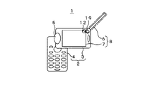
携帯電話機1は、図3に示すようにヒンジ機構5を介して第2筐体4に対して第1筐体3を直線上に位置させるように展開した状態で、支持部19を介して第1筐体3に対してロッドアンテナ6を側方へ水平状態で展開させた形態にして使用することも可能である。携帯電話機1においては、かかる使用形態で、第1筐体3とロッドアンテナ6とによりL字状ダイポールを構成する。   As shown in FIG. 3, the cellular phone 1 is unfolded via the support portion 19 in a state where the first housing 3 is linearly positioned with respect to the second housing 4 via the hinge mechanism 5. It is also possible to use the rod antenna 6 in a form in which the rod antenna 6 is horizontally expanded with respect to one housing 3. In the mobile phone 1, an L-shaped dipole is configured by the first housing 3 and the rod antenna 6 in such a usage pattern.

携帯電話機1は、図4に示すようにヒンジ機構5を介して第2筐体4に対して第1筐体3を直線上に位置させるように展開した状態で、支持部19を介して第1筐体3に対してロッドアンテナ6を側方に所定の角度を付した形態にして使用することも可能である。携帯電話機1においては、かかる使用形態で、第1筐体3とロッドアンテナ6とによりV字状ダイポールを構成する。   As shown in FIG. 4, the cellular phone 1 is unfolded via the support portion 19 in a state where the first housing 3 is linearly positioned with respect to the second housing 4 via the hinge mechanism 5. It is also possible to use the rod antenna 6 in a form in which a predetermined angle is given to the side with respect to one housing 3. In the mobile phone 1, a V-shaped dipole is configured by the first housing 3 and the rod antenna 6 in this usage pattern.

携帯電話機1においては、上述したように多様の形態のダイポールアンテナ8を構成することにより、垂直偏波と水平偏波とが混在する都市部等におけるマルチパスフェージング環境(移動送受信の環境)下において、アンテナの偏波特性を変化させて使用することが可能である。したがって、携帯電話機1においては、良好な状態で送受信を行うことが可能である。   In the mobile phone 1, as described above, the dipole antenna 8 having various forms is configured, so that the mobile phone 1 can be used in a multipath fading environment (mobile transmission / reception environment) in an urban area where vertical polarization and horizontal polarization are mixed. It is possible to change the polarization characteristics of the antenna. Therefore, the mobile phone 1 can perform transmission / reception in a good state.

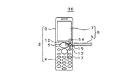
携帯電話機1においては、筐体2が把持するに足る幅とされるとともに、大型の画面化を図るために液晶表示器9が縦長画面の状態で第1筐体3に設けられている。携帯電話機1においては、図5乃至図7に示すように、ヒンジ機構5を介して第2筐体4に対して第1筐体3を直交する水平状態に展開することによって、第1筐体3側に設けた液晶表示器9を横長の形態として使用することも可能である。   In the cellular phone 1, the casing 2 is wide enough to be gripped, and the liquid crystal display 9 is provided in the first casing 3 in a state of a vertically long screen in order to realize a large screen. In the mobile phone 1, as shown in FIGS. 5 to 7, the first housing 3 is deployed in a horizontal state orthogonal to the second housing 4 via the hinge mechanism 5, thereby It is also possible to use the liquid crystal display 9 provided on the side 3 as a horizontally long form.

携帯電話機1においては、例えば携帯端末向け地上波デジタル放送(ISDB-T:Integrated Services Digital Broadcasting-Terrestrial)の放送番組を受信する機能やその他の動画或いは静止画等の画像コンテンツの受信機能も備えられる。携帯電話機1においては、一般にこれらの端末画面が横長画面として用いられていることから、上述したように第2筐体4に対して第1筐体3を直交する水平状態に展開することによって液晶表示器9を横長画面とすることによって、違和感を生じさせずに映像や画像の表示が行われるようにすることが可能である。   For example, the mobile phone 1 has a function of receiving a broadcast program of terrestrial digital broadcasting (ISDB-T: Integrated Services Digital Broadcasting-Terrestrial) for mobile terminals, and a function of receiving image content such as other moving images or still images. . In the mobile phone 1, since these terminal screens are generally used as landscape screens, the liquid crystal can be obtained by developing the first housing 3 in a horizontal state orthogonal to the second housing 4 as described above. By making the display 9 a horizontally long screen, it is possible to display video and images without causing a sense of incongruity.

携帯電話機1においては、図5に示すようにヒンジ機構5を介して第2筐体4に対して第1筐体3を直交する水平状態に展開するとともに、支持部19を介して第1筐体3に対してロッドアンテナ6を平行に展開して使用することが可能である。携帯電話機1においては、かかる使用形態で、第1筐体3とロッドアンテナ6とにより直線状ダイポールを構成する。   In the mobile phone 1, as shown in FIG. 5, the first housing 3 is expanded in a horizontal state orthogonal to the second housing 4 via the hinge mechanism 5, and the first housing is supported via the support portion 19. The rod antenna 6 can be deployed in parallel with the body 3 and used. In the mobile phone 1, a linear dipole is constituted by the first housing 3 and the rod antenna 6 in such a usage pattern.

また、携帯電話機1においては、図6に示すようにヒンジ機構5を介して第2筐体4に対して第1筐体3を直交する水平状態に展開するとともに、支持部19を介して第1筐体3に対してロッドアンテナ6を直角に立てるようにして展開して使用することが可能である。携帯電話機1においては、かかる使用形態で、第1筐体3とロッドアンテナ6とによりL字状ダイポールを構成する。   Further, in the mobile phone 1, as shown in FIG. 6, the first housing 3 is expanded in a horizontal state orthogonal to the second housing 4 via the hinge mechanism 5, and the first housing 3 is interposed via the support portion 19. The rod antenna 6 can be deployed and used so as to stand at a right angle with respect to one housing 3. In the mobile phone 1, an L-shaped dipole is configured by the first housing 3 and the rod antenna 6 in such a usage pattern.

さらに、携帯電話機1においては、図7に示すようにヒンジ機構5を介して第2筐体4に対して第1筐体3を直交する水平状態に展開するとともに、支持部19を介して第1筐体3に対してロッドアンテナ6を角度を付して展開して使用することが可能である。携帯電話機1においては、かかる使用形態で、第1筐体3とロッドアンテナ6とによりV字状ダイポールを構成する。   Furthermore, in the mobile phone 1, as shown in FIG. 7, the first housing 3 is expanded in a horizontal state orthogonal to the second housing 4 via the hinge mechanism 5, and the first housing 3 is interposed via the support portion 19. It is possible to use the rod antenna 6 by expanding the rod antenna 6 at an angle with respect to one housing 3. In the mobile phone 1, a V-shaped dipole is configured by the first housing 3 and the rod antenna 6 in this usage pattern.

携帯電話機1においては、上述したようにダイポールアンテナ8の第1アンテナエレメントを構成する第1筐体3を水平状態として使用することにより、この第1筐体3が水平偏波特性を有するようになる。携帯電話機1においては、水平偏波放送の地上波デジタル放送を受信する際に、ダイポールアンテナ8が水平偏波特性を有することでより高感度で放送電波を受信することが可能である。   In the mobile phone 1, as described above, the first casing 3 constituting the first antenna element of the dipole antenna 8 is used in a horizontal state so that the first casing 3 has horizontal polarization characteristics. become. In the mobile phone 1, when receiving a terrestrial digital broadcast of horizontal polarization broadcast, the dipole antenna 8 has a horizontal polarization characteristic, so that it is possible to receive broadcast radio waves with higher sensitivity.

携帯電話機1においては、上述したように第2筐体4側にメインの第2回路基板16が内蔵され、この第2回路基板16に制御回路部や或いはダイヤル発信回路モジュールや電源回路等が搭載される。携帯電話機1においては、損失等を抑制して信号処理を行うようにするために第2回路基板16に無線送受信回路モジュール17が搭載される。携帯電話機1においては、無線送受信回路モジュール17によってダイポールアンテナ8により受信した電波を処理したり送信情報が処理される。携帯電話機1においては、第1筐体3側の高周波電源部12と第2筐体4側の無線送受信回路モジュール17とを同軸ケーブル13によって接続している。   In the mobile phone 1, as described above, the main second circuit board 16 is built in the second housing 4, and a control circuit unit, a dial transmission circuit module, a power supply circuit, and the like are mounted on the second circuit board 16. Is done. In the mobile phone 1, a wireless transmission / reception circuit module 17 is mounted on the second circuit board 16 in order to perform signal processing while suppressing loss and the like. In the mobile phone 1, the radio transmission / reception circuit module 17 processes radio waves received by the dipole antenna 8 and transmission information. In the mobile phone 1, the high frequency power supply unit 12 on the first housing 3 side and the wireless transmission / reception circuit module 17 on the second housing 4 side are connected by a coaxial cable 13.

携帯電話機1においては、上述したように第1筐体3の先端部の近傍に位置して設けられた支持部19を介してロッドアンテナ6が展開自在に組み合わされている。携帯電話機1においては、このために同軸ケーブル13が第1筐体3の内部を全長に亘って引き回されて第2筐体4側に引き出される構造となる。携帯電話機1においては、第1筐体3に大きな部品として液晶表示器9が内蔵されているが同軸ケーブル13の引き回しスペースを確保することが可能である。   In the mobile phone 1, the rod antenna 6 is combined in a freely deployable manner via the support portion 19 provided in the vicinity of the distal end portion of the first housing 3 as described above. For this purpose, the cellular phone 1 has a structure in which the coaxial cable 13 is drawn over the entire length of the first housing 3 and pulled out to the second housing 4 side. In the mobile phone 1, the liquid crystal display 9 is incorporated as a large component in the first housing 3, but a space for the coaxial cable 13 can be secured.

しかしながら、携帯電話機1においては、例えばカメラ機能等を搭載する多機能化が図られることにより、第1筐体3のスペース確保も困難となってくる。また、携帯電話機1においては、高周波電源部12と無線送受信回路モジュール17との間隔が大きくなることにより、線路損失も大きくなる。携帯電話機1においては、同軸ケーブル13を用いることによってノイズの重畳が抑制されるが、線路長を短縮化したほうが好ましい。   However, in the mobile phone 1, for example, a space for the first housing 3 is difficult to be secured due to the multi-functionality equipped with, for example, a camera function. Further, in the mobile phone 1, the line loss increases due to the increase in the distance between the high-frequency power supply unit 12 and the radio transmission / reception circuit module 17. In the mobile phone 1, the use of the coaxial cable 13 suppresses noise superimposition, but it is preferable to shorten the line length.

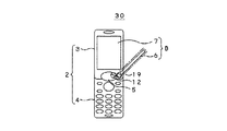
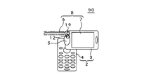
第2の実施の形態として図8乃至図12に示した携帯電話機30は、ロッドアンテナ6を支持する支持部19を第1筐体3のヒンジ機構5側に位置して設けることにより、高周波電源部12と無線送受信回路モジュール17との間隔を短縮化してなる。なお、携帯電話機30は、第1筐体3に対するロッドアンテナ6の支持位置を異にする以外の構成を上述した携帯電話機1と同様とすることから、対応する部位に同一符号を付すことにより説明を省略する。   The mobile phone 30 shown in FIGS. 8 to 12 as the second embodiment is provided with a support portion 19 that supports the rod antenna 6 so as to be positioned on the hinge mechanism 5 side of the first housing 3. The interval between the unit 12 and the wireless transmission / reception circuit module 17 is shortened. Since the mobile phone 30 has the same configuration as that of the mobile phone 1 described above except that the support position of the rod antenna 6 with respect to the first housing 3 is different, the same reference numerals are given to corresponding portions. Is omitted.

携帯電話機30においても、ロッドアンテナ6と導体部7に高周波電源部12から平衡給電が行われるが、この高周波電源部12に対して平衡・不平衡変換素子14を介して一端を第2筐体4側の無線送受信回路モジュール17と接続された同軸ケーブル13の他端が接続される。携帯電話機30においては、高周波電源部12も第1筐体3内においてヒンジ機構5側に位置して設けられることにより、同軸ケーブル13の短縮化が図られる。   Also in the cellular phone 30, balanced power is supplied from the high frequency power supply unit 12 to the rod antenna 6 and the conductor unit 7. One end of the high frequency power supply unit 12 is connected to the second housing via the balanced / unbalanced conversion element 14. The other end of the coaxial cable 13 connected to the four-side radio transceiver circuit module 17 is connected. In the mobile phone 30, the coaxial cable 13 can be shortened by providing the high-frequency power supply unit 12 also on the hinge mechanism 5 side in the first housing 3.

かかる携帯電話機30においても、第1筐体3が第2筐体4に対してヒンジ機構5を介して展開自在に組み合わされるとともに、ロッドアンテナ6が第1筐体3に対して支持部19を介して展開自在に組み合わされることから、多様な形態のダイポールアンテナ8を構成することが可能である。携帯電話機30においては、図8に示すように、ヒンジ機構5を介して第2筐体4に対して第1筐体3を直線上に位置させるように展開した状態で、支持部19を介して第1筐体3に対してロッドアンテナ6を側方へ水平状態で展開させた形態にして使用することも可能である。携帯電話機30は、かかる使用形態で、第1筐体3とロッドアンテナ6とによりL字状ダイポールを構成する。   Also in such a cellular phone 30, the first housing 3 is combined with the second housing 4 via the hinge mechanism 5 so as to be freely deployable, and the rod antenna 6 supports the support portion 19 with respect to the first housing 3. Therefore, the dipole antenna 8 can be configured in various forms. In the mobile phone 30, as shown in FIG. 8, the first housing 3 is unfolded so as to be positioned on a straight line with respect to the second housing 4 via the hinge mechanism 5, and the support portion 19 is interposed. It is also possible to use the rod antenna 6 in a state in which the rod antenna 6 is expanded laterally with respect to the first housing 3. The mobile phone 30 forms an L-shaped dipole with the first housing 3 and the rod antenna 6 in this usage pattern.

また、携帯電話機30は、図9に示すようにヒンジ機構5を介して第2筐体4に対して第1筐体3を直線上に位置させるように展開した状態で、支持部19を介して第1筐体3に対してロッドアンテナ6を側方へ角度を付して展開して使用することが可能である。携帯電話機30においては、かかる使用形態で、第1筐体3とロッドアンテナ6とによりV字状ダイポールを構成する。   In addition, the mobile phone 30 is provided via the support unit 19 in a state where the first case 3 is linearly positioned with respect to the second case 4 via the hinge mechanism 5 as shown in FIG. Thus, it is possible to use the rod antenna 6 by expanding the rod antenna 6 at an angle with respect to the first housing 3. In the cellular phone 30, a V-shaped dipole is configured by the first housing 3 and the rod antenna 6 in this usage pattern.

携帯電話機30においては、第1筐体3に設けた液晶表示器9を横長とするとともに、多様な形態のダイポールアンテナ8を構成することも可能である。携帯電話機30においては、図10に示すようにヒンジ機構5を介して第2筐体4に対して第1筐体3を直交する水平状態に展開するとともに、支持部19を介してロッドアンテナ6を第1筐体4と対向するように平行に展開して使用することが可能である。携帯電話機30においては、かかる使用形態で、第1筐体3とロッドアンテナ6とにより直線状ダイポールを構成する。   In the mobile phone 30, the liquid crystal display 9 provided in the first housing 3 can be horizontally long, and various forms of the dipole antenna 8 can be configured. In the cellular phone 30, as shown in FIG. 10, the first housing 3 is expanded in a horizontal state perpendicular to the second housing 4 via the hinge mechanism 5, and the rod antenna 6 is supported via the support portion 19. Can be used in parallel so as to face the first housing 4. In the mobile phone 30, a linear dipole is configured by the first housing 3 and the rod antenna 6 in such a usage pattern.

携帯電話機30においては、図11に示すようにヒンジ機構5を介して第2筐体4に対して第1筐体3を直交する水平状態に展開するとともに、支持部19を介してロッドアンテナ6を第1筐体3に対して直交する垂直方向に展開して使用することが可能である。携帯電話機30においては、かかる使用形態で、第1筐体3とロッドアンテナ6とによりL字状ダイポールを構成する。   In the mobile phone 30, as shown in FIG. 11, the first housing 3 is expanded in a horizontal state orthogonal to the second housing 4 via the hinge mechanism 5, and the rod antenna 6 is supported via the support portion 19. Can be expanded and used in a vertical direction perpendicular to the first housing 3. In the cellular phone 30, an L-shaped dipole is configured by the first housing 3 and the rod antenna 6 in this usage pattern.

携帯電話機30においては、図12に示すようにヒンジ機構5を介して第2筐体4に対して第1筐体3を直交する水平状態に展開するとともに、支持部19を介してロッドアンテナ6を第1筐体3に対して垂直方向から角度を付した状態で展開して使用することが可能である。携帯電話機30においては、かかる使用形態で、第1筐体3とロッドアンテナ6とによりV字状ダイポールを構成する。   In the mobile phone 30, as shown in FIG. 12, the first housing 3 is expanded in a horizontal state orthogonal to the second housing 4 via the hinge mechanism 5, and the rod antenna 6 is supported via the support portion 19. Can be deployed and used in a state where the first housing 3 is angled from the vertical direction. In the cellular phone 30, a V-shaped dipole is configured by the first housing 3 and the rod antenna 6 in this usage pattern.

なお、本発明は、上述した実施の形態として示した携帯電話機に限定されず、例えば携帯型テレビジョン受像機や携帯型情報端末装置(PDA:Personal Digital Assistant)等の各種の移動体無線機器にも適用されることは勿論である。   The present invention is not limited to the mobile phone shown as the above-described embodiment, and may be applied to various mobile wireless devices such as a portable television receiver and a portable information terminal device (PDA: Personal Digital Assistant). Of course, this also applies.

実施の形態として示す携帯電話機の使用状態を示す要部正面図である。It is a principal part front view which shows the use condition of the mobile telephone shown as embodiment. 携帯電話機の構成図である。It is a block diagram of a mobile phone. 携帯電話機において、ロッドアンテナを第1筐体に対して側方へ水平状態に展開してL字状ダイポールを構成した使用状態の要部正面図である。FIG. 5 is a front view of a main part in a use state in which an L-shaped dipole is configured by deploying a rod antenna in a horizontal state laterally with respect to a first housing in a mobile phone. 携帯電話機において、ロッドアンテナを第1筐体に対して側方に角度を付した状態で展開してV字状ダイポールを構成した使用状態の要部正面図である。FIG. 3 is a front view of a main part in a use state in which a rod antenna is developed in a state in which a rod antenna is angled laterally with respect to a first housing to constitute a V-shaped dipole. 携帯電話機において、第1筐体を第2筐体に対して直交する水平状態に展開するとともにロッドアンテナを第1筐体と平行に展開して直線状ダイポールを構成した使用状態の要部正面図である。The main part front view of the use state which expanded the 1st housing | casing in the horizontal state orthogonal to the 2nd housing | casing and comprised the rod antenna parallel to the 1st housing | casing and comprised the linear dipole in the mobile telephone. It is. 携帯電話機において、第1筐体を第2筐体に対して直交する水平状態に展開するとともにロッドアンテナを第1筐体に対して直交する垂直方向に展開してL字状ダイポールを構成した使用状態の要部正面図である。In a cellular phone, the first housing is deployed in a horizontal state orthogonal to the second housing, and the rod antenna is deployed in a vertical direction orthogonal to the first housing to form an L-shaped dipole. It is a principal part front view of a state. 携帯電話機において、第1筐体を第2筐体に対して直交する水平状態に展開するとともにロッドアンテナを第1筐体に対して角度を付して展開してV字状ダイポールを構成した使用状態の要部正面図である。In a cellular phone, the first housing is deployed in a horizontal state orthogonal to the second housing, and the rod antenna is deployed at an angle with respect to the first housing to form a V-shaped dipole. It is a principal part front view of a state. 第2の実施の形態として示す携帯電話機において、ロッドアンテナを第1筐体に対して側方へ水平状態で展開してL字状ダイポールを構成した使用状態の要部正面図である。In the mobile phone shown as the second embodiment, it is a front view of an essential part in a use state in which an L-shaped dipole is configured by deploying a rod antenna in a horizontal state laterally with respect to a first housing. 第2の実施の形態として示す携帯電話機において、ロッドアンテナを第1筐体に対して側方に角度を付した状態で展開してV字状ダイポールを構成した使用状態の要部正面図である。In the mobile phone shown as the second embodiment, the rod antenna is unfolded in a state of being angled laterally with respect to the first housing, and a V-shaped dipole is configured to be a main part front view in a use state. . 第3の実施の形態として示す携帯電話機において、第1筐体を第2筐体に対して直交する水平状態に展開するとともにロッドアンテナを第1筐体と対向するように平行に展開して直線状ダイポールを構成した使用状態の要部正面図である。In the mobile phone shown as the third embodiment, the first casing is expanded in a horizontal state orthogonal to the second casing, and the rod antenna is expanded in parallel so as to face the first casing. It is a principal part front view of the use condition which comprised the shape dipole. 第3の実施の形態として示す携帯電話機において、第1筐体を第2筐体に対して直交する水平状態に展開するとともにロッドアンテナを第1筐体に対して直交する垂直方向に展開してL字状ダイポールを構成した使用状態の要部正面図である。In the mobile phone shown as the third embodiment, the first casing is expanded in a horizontal state orthogonal to the second casing, and the rod antenna is expanded in a vertical direction orthogonal to the first casing. It is a principal part front view of the use condition which comprised the L-shaped dipole. 第3の実施の形態として示す携帯電話機において、第1筐体を第2筐体に対して直交する水平状態に展開するとともにロッドアンテナを第1筐体に対して垂直方向から角度を付した状態で展開してV字状ダイポールを構成した使用状態の要部正面図である。In the mobile phone shown as the third embodiment, the first housing is deployed in a horizontal state orthogonal to the second housing and the rod antenna is angled from the vertical direction with respect to the first housing It is a principal part front view of the use condition which expanded | deployed and comprised the V-shaped dipole.

符号の説明Explanation of symbols

1 携帯電話機、2 筐体、3 第1筐体、4 第2筐体、5 ヒンジ機構、6 ロッドアンテナ、7 導体部、8 ダイポールアンテナ、11 回路基板、12 高周波電源部、13 同軸ケーブル、14 平衡・不平衡変換素子、16 回路基板、17 無線送受信回路モジュール、19 支持部、20 アンテナエレメント、22 フレキシブル回路基板
DESCRIPTION OF SYMBOLS 1 Mobile phone, 2 housing | casing, 3 1st housing | casing, 2nd housing | casing, 5 Hinge mechanism, 6 Rod antenna, 7 Conductor part, 8 Dipole antenna, 11 Circuit board, 12 High frequency power supply part, 13 Coaxial cable, 14 Balance / unbalance conversion element, 16 circuit board, 17 wireless transmission / reception circuit module, 19 support, 20 antenna element, 22 flexible circuit board

Claims (4)

少なくとも第1筐体と第2筐体とに分割され、これら第1筐体と第2筐体とがヒンジ機構を介して展開自在に結合された筐体を備える携帯型無線端末装置において、
上記第1筐体の導体部によって第1アンテナエレメントを構成するとともに、上記第1筐体に対して展開自在に支持されたアンテナ部材によって第2アンテナエレメントを構成し、これら第1アンテナエレメントと第2アンテナエレメントに対して上記第2筐体側に設けた無線送受信回路部から平衡・不平衡変換素子を介して平衡給電を行うことによって平衡アンテナを構成し、
上記第1筐体側に設けた上記平衡・不平衡変換器と上記第2筐体側に設けた上記無線送受信回路部との給電線に同軸ケーブルを用るとともに、上記同軸ケーブルを介して上記第1筐体側の回路部と上記第2筐体側の回路部との信号線路と独立してグランド接続を行うことを特徴とする携帯型無線端末装置。
In a portable wireless terminal device including a housing that is divided into at least a first housing and a second housing, and the first housing and the second housing are coupled to each other via a hinge mechanism so as to be expandable.
The first antenna element is configured by the conductor portion of the first casing, and the second antenna element is configured by the antenna member supported so as to be expandable with respect to the first casing. A balanced antenna is configured by performing balanced power feeding via a balanced / unbalanced conversion element from the wireless transmission / reception circuit unit provided on the second housing side for the two antenna elements,
A coaxial cable is used as a power supply line between the balanced / unbalanced converter provided on the first housing side and the wireless transmission / reception circuit unit provided on the second housing side, and the first cable is connected via the coaxial cable. A portable wireless terminal device, wherein ground connection is performed independently of a signal line between a circuit unit on a housing side and a circuit unit on the second housing side.
上記アンテナ部材が、上記第1筐体に対して、上記ヒンジ機構を設けた上記第2筐体との結合部と対向する側に位置して設けられることを特徴とする請求項1に記載の携帯型無線端末装置。   The said antenna member is located in the side facing the coupling | bond part with the said 2nd housing | casing which provided the said hinge mechanism with respect to the said 1st housing | casing, It is provided. Portable wireless terminal device. 上記アンテナ部材が、上記第1筐体に対して、上記ヒンジ機構を設けた上記第2筐体との結合部側に位置して部位に設けられることを特徴とする請求項1に記載の携帯型無線端末装置。   2. The mobile phone according to claim 1, wherein the antenna member is provided at a part of the first housing that is positioned on a coupling portion side with the second housing provided with the hinge mechanism. Type wireless terminal device. 上記アンテナ部材が、上記第1筐体に対して、適宜の展開角度で保持されることを特徴とする請求項1に記載の携帯型無線端末装置。
The portable wireless terminal device according to claim 1, wherein the antenna member is held at an appropriate deployment angle with respect to the first housing.
JP2005148604A 2005-05-20 2005-05-20 Portable wireless terminal device Expired - Fee Related JP4626398B2 (en)

Priority Applications (1)

Application Number Priority Date Filing Date Title
JP2005148604A JP4626398B2 (en) 2005-05-20 2005-05-20 Portable wireless terminal device

Applications Claiming Priority (1)

Application Number Priority Date Filing Date Title
JP2005148604A JP4626398B2 (en) 2005-05-20 2005-05-20 Portable wireless terminal device

Publications (2)

Publication Number Publication Date
JP2006325152A true JP2006325152A (en) 2006-11-30
JP4626398B2 JP4626398B2 (en) 2011-02-09

Family

ID=37544453

Family Applications (1)

Application Number Title Priority Date Filing Date
JP2005148604A Expired - Fee Related JP4626398B2 (en) 2005-05-20 2005-05-20 Portable wireless terminal device

Country Status (1)

Country Link
JP (1) JP4626398B2 (en)

Cited By (3)

* Cited by examiner, † Cited by third party
Publication number Priority date Publication date Assignee Title
JP2009038473A (en) * 2007-07-31 2009-02-19 Casio Hitachi Mobile Communications Co Ltd Folding communication terminal
JP2010011236A (en) * 2008-06-27 2010-01-14 Fujitsu Ltd Electronic apparatus
JP2010268167A (en) * 2009-05-13 2010-11-25 Tokai Rika Co Ltd Antenna device

Citations (3)

* Cited by examiner, † Cited by third party
Publication number Priority date Publication date Assignee Title
JPH10150313A (en) * 1996-11-19 1998-06-02 Mitsubishi Electric Corp Portable information terminal
JP2004179995A (en) * 2002-11-27 2004-06-24 Matsushita Electric Ind Co Ltd Radio communication apparatus
JP2004228790A (en) * 2003-01-21 2004-08-12 Sony Ericsson Mobilecommunications Japan Inc Antenna system and mobile wireless apparatus

Patent Citations (3)

* Cited by examiner, † Cited by third party
Publication number Priority date Publication date Assignee Title
JPH10150313A (en) * 1996-11-19 1998-06-02 Mitsubishi Electric Corp Portable information terminal
JP2004179995A (en) * 2002-11-27 2004-06-24 Matsushita Electric Ind Co Ltd Radio communication apparatus
JP2004228790A (en) * 2003-01-21 2004-08-12 Sony Ericsson Mobilecommunications Japan Inc Antenna system and mobile wireless apparatus

Cited By (3)

* Cited by examiner, † Cited by third party
Publication number Priority date Publication date Assignee Title
JP2009038473A (en) * 2007-07-31 2009-02-19 Casio Hitachi Mobile Communications Co Ltd Folding communication terminal
JP2010011236A (en) * 2008-06-27 2010-01-14 Fujitsu Ltd Electronic apparatus
JP2010268167A (en) * 2009-05-13 2010-11-25 Tokai Rika Co Ltd Antenna device

Also Published As

Publication number Publication date
JP4626398B2 (en) 2011-02-09

Similar Documents

Publication Publication Date Title
JP4242780B2 (en) Balanced multiband antenna device
JP3613525B2 (en) Portable radio
US7821463B2 (en) Mobile telephone with broadcast receiving element
US7839340B2 (en) Collapsable portable wireless unit
JP4660633B2 (en) transceiver
JP2006025392A (en) Earphone cable antenna device, connection cable, and broadcast receiving apparatus
WO2006011322A1 (en) Mobile telephone device
KR20060092062A (en) Wireless communication apparatus
WO2005107082A1 (en) Portable telephone with broadcast receiver
JPWO2006046714A1 (en) Mobile phone with broadcast receiver
US7911392B2 (en) Multiple frequency band antenna assembly for handheld communication devices
JPWO2009019782A1 (en) ANTENNA DEVICE AND PORTABLE RADIO DEVICE
US8232926B2 (en) Mobile wireless device
WO2002056415A1 (en) Built-in anenna of portable radio apparatus
JP2000174527A (en) Portable electronic device
JP2007074491A (en) Portable terminal
JP4626398B2 (en) Portable wireless terminal device
JP2006067133A (en) Folding type portable radio device
JP2002171111A (en) Portable radio and antenna for it
WO2006129400A1 (en) Portable wireless apparatus
WO2011135851A1 (en) Wireless terminal
JP2007013442A (en) Portable radio equipment
JP2001230613A (en) Antenna system and portable radio equipment
JP2020519082A (en) Millimeter wave antenna
JP2003264414A (en) Foldable portable radio terminal

Legal Events

Date Code Title Description
A621 Written request for application examination

Free format text: JAPANESE INTERMEDIATE CODE: A621

Effective date: 20080327

A977 Report on retrieval

Free format text: JAPANESE INTERMEDIATE CODE: A971007

Effective date: 20100727

A131 Notification of reasons for refusal

Free format text: JAPANESE INTERMEDIATE CODE: A131

Effective date: 20100803

A521 Written amendment

Free format text: JAPANESE INTERMEDIATE CODE: A523

Effective date: 20100831

TRDD Decision of grant or rejection written
A01 Written decision to grant a patent or to grant a registration (utility model)

Free format text: JAPANESE INTERMEDIATE CODE: A01

Effective date: 20101012

A01 Written decision to grant a patent or to grant a registration (utility model)

Free format text: JAPANESE INTERMEDIATE CODE: A01

A61 First payment of annual fees (during grant procedure)

Free format text: JAPANESE INTERMEDIATE CODE: A61

Effective date: 20101025

FPAY Renewal fee payment (event date is renewal date of database)

Free format text: PAYMENT UNTIL: 20131119

Year of fee payment: 3

FPAY Renewal fee payment (event date is renewal date of database)

Free format text: PAYMENT UNTIL: 20131119

Year of fee payment: 3

LAPS Cancellation because of no payment of annual fees