EP2302190A1 - Exhaust gas recycling system - Google Patents
Exhaust gas recycling system Download PDFInfo
- Publication number
- EP2302190A1 EP2302190A1 EP09290726A EP09290726A EP2302190A1 EP 2302190 A1 EP2302190 A1 EP 2302190A1 EP 09290726 A EP09290726 A EP 09290726A EP 09290726 A EP09290726 A EP 09290726A EP 2302190 A1 EP2302190 A1 EP 2302190A1
- Authority
- EP
- European Patent Office
- Prior art keywords
- exhaust gas
- heat exchanger
- gas recirculation
- point
- recirculation system
- Prior art date
- Legal status (The legal status is an assumption and is not a legal conclusion. Google has not performed a legal analysis and makes no representation as to the accuracy of the status listed.)
- Granted
Links
Images

Classifications
-
- F—MECHANICAL ENGINEERING; LIGHTING; HEATING; WEAPONS; BLASTING
- F02—COMBUSTION ENGINES; HOT-GAS OR COMBUSTION-PRODUCT ENGINE PLANTS
- F02M—SUPPLYING COMBUSTION ENGINES IN GENERAL WITH COMBUSTIBLE MIXTURES OR CONSTITUENTS THEREOF
- F02M26/00—Engine-pertinent apparatus for adding exhaust gases to combustion-air, main fuel or fuel-air mixture, e.g. by exhaust gas recirculation [EGR] systems
- F02M26/02—EGR systems specially adapted for supercharged engines
- F02M26/04—EGR systems specially adapted for supercharged engines with a single turbocharger
- F02M26/07—Mixed pressure loops, i.e. wherein recirculated exhaust gas is either taken out upstream of the turbine and reintroduced upstream of the compressor, or is taken out downstream of the turbine and reintroduced downstream of the compressor
-
- F—MECHANICAL ENGINEERING; LIGHTING; HEATING; WEAPONS; BLASTING
- F02—COMBUSTION ENGINES; HOT-GAS OR COMBUSTION-PRODUCT ENGINE PLANTS
- F02M—SUPPLYING COMBUSTION ENGINES IN GENERAL WITH COMBUSTIBLE MIXTURES OR CONSTITUENTS THEREOF
- F02M26/00—Engine-pertinent apparatus for adding exhaust gases to combustion-air, main fuel or fuel-air mixture, e.g. by exhaust gas recirculation [EGR] systems
- F02M26/13—Arrangement or layout of EGR passages, e.g. in relation to specific engine parts or for incorporation of accessories
- F02M26/22—Arrangement or layout of EGR passages, e.g. in relation to specific engine parts or for incorporation of accessories with coolers in the recirculation passage
- F02M26/33—Arrangement or layout of EGR passages, e.g. in relation to specific engine parts or for incorporation of accessories with coolers in the recirculation passage controlling the temperature of the recirculated gases
-
- Y—GENERAL TAGGING OF NEW TECHNOLOGICAL DEVELOPMENTS; GENERAL TAGGING OF CROSS-SECTIONAL TECHNOLOGIES SPANNING OVER SEVERAL SECTIONS OF THE IPC; TECHNICAL SUBJECTS COVERED BY FORMER USPC CROSS-REFERENCE ART COLLECTIONS [XRACs] AND DIGESTS
- Y02—TECHNOLOGIES OR APPLICATIONS FOR MITIGATION OR ADAPTATION AGAINST CLIMATE CHANGE
- Y02T—CLIMATE CHANGE MITIGATION TECHNOLOGIES RELATED TO TRANSPORTATION
- Y02T10/00—Road transport of goods or passengers
- Y02T10/10—Internal combustion engine [ICE] based vehicles
- Y02T10/12—Improving ICE efficiencies
Definitions
- the invention relates to an exhaust gas recirculation system with an internal combustion engine, which is branched off at a sampling point and fed back via a return point exhaust gas and / or charge air, arranged between the removal point and the return point heat exchanger for the recirculated exhaust gas and / or the charge air, and with a Exhaust gas recirculation valve, via which the recirculated exhaust gas and / or charge air quantity can be regulated.
- an exhaust gas recirculation line is known with a heat exchanger arranged between an engine and a catalyst pot in series with constricting means for generating a back pressure, the heat exchanger flow being upwardly from the constricting means.
- an exhaust gas recirculation valve is connected downstream of the heat exchanger.
- a throttle plate is connected in parallel to the heat exchanger.
- a heat exchanger is interposed between an exhaust catalyst pot and a catalytic element.
- German patent application DE 102 59 702 A1 is an exhaust system for a heat engine with a waste heat recovery area for recovering heat from the exhaust gas and for transferring the recovered heat to a heat medium disposed in the exhaust pipe.
- a burner is provided in the exhaust pipe, which is also referred to as Combuster.
- the object of the invention is to provide an exhaust gas recirculation system according to the preamble of claim 1, which is simple in construction and inexpensive to produce.
- the object is in an exhaust gas recirculation system with an internal combustion engine, which is branched off at a sampling point and fed back via a recirculation exhaust and / or charge air, with a arranged between the sampling point and the return point heat exchanger for the recirculated exhaust gas and / or the charge air, and with an exhaust gas recirculation valve, via which the recirculated exhaust gas and / or charge air quantity can be regulated, achieved in that the exhaust gas recirculation valve is connected between the extraction point and the heat exchanges.
- the entire exhaust branched off at the extraction point or the entire charge air branched there is passed through the heat exchanger for heat exchange.
- a preferred embodiment of the exhaust gas recirculation system is characterized in that the heat exchanger is associated with a branch valve, via which the exhausted at the sampling point and exiting the heat exchanger exhaust gas and / or the charge air is returned via the return point or discharged via a branch line.
- the branch valve the branched off at the sampling exhaust and / or the charge air, at least partially, together with the not branched off at the sampling exhaust gas via an exhaust system, which optionally comprises a catalyst device, are discharged into the environment.
- Another preferred embodiment of the exhaust gas recirculation system is characterized in that the branched off at the sampling point and exiting the heat exchanger exhaust gas and / or the charge air through the branch valve is wholly or partially returned via the return point or discharged via the branch line.
- the heat exchanger can be used in a warm-up phase of the internal combustion engine to cool the waste gas branched off at the removal point for heat recovery.
- the heat exchanger may be used to cool the exhaust gas recirculated at the recycle point to recover heat.
- Another preferred embodiment of the exhaust gas recirculation system is characterized in that the branch valve is integrated into the heat exchanger.
- the exhaust gas recirculation valve can be integrated in the heat exchanger.
- a further preferred embodiment of the exhaust gas recirculation system is characterized in that the branch valve is provided at an outlet of the heat exchanger.
- a further preferred exemplary embodiment of the exhaust gas recirculation system is characterized in that the heat exchanger can only be flowed through or flowed through in one direction by the exhaust gas branched off at the removal point and / or by the charge air.
- a heat exchanger is also referred to as a 1-flow heat exchanger.
- Another preferred embodiment of the exhaust gas recirculation system is characterized in that the branch line and a return line are connected to one end of the heat exchanger.
- the other of two ends of the heat exchanger is preferably in communication with the exhaust gas discharge point and / or the charge air.
- a further preferred embodiment of the exhaust gas recirculation system is characterized in that the heat exchanger in opposite directions from the exhaust branched off at the sampling point and / or the charge air can be flowed through or flowed through. Such a heat exchanger is also referred to as a U-flow heat exchanger.
- a further preferred embodiment of the exhaust gas recirculation system is characterized in that the branch line is connected to one end of the heat exchanger, which communicates with the removal point for the exhaust gas and / or the charge air. It is thereby achieved that the exhaust branched off at the removal point, which is not returned to the return point, flows through the heat exchanger several times. As a result, the heat recovery can be further improved.
- a further preferred embodiment of the exhaust gas recirculation system is characterized in that a return line is connected to the other of two ends of the heat exchanger. In the return line, a filter may be arranged.
- a further preferred embodiment of the exhaust gas recirculation system is characterized in that the withdrawal point is followed by a back pressure valve.
- the back pressure valve is used to build up a back pressure at the sampling point. Thereby, the temperature of the exhaust gas can be increased and the heat recovery can be improved.
- a further preferred embodiment of the exhaust gas recirculation system is characterized in that between the internal combustion engine and the removal point, a further removal point is provided which can be connected via a further exhaust gas recirculation valve with a further return point, which is provided between the return point and the internal combustion engine.
- a further preferred embodiment of the exhaust gas recirculation system is characterized in that between the return point and the internal combustion engine, a compressor for the exhaust gas and / or the charge air is provided, which is driven by a turbine, which is provided between the internal combustion engine and the removal point.
- the further removal point is preferably between the internal combustion engine and the turbine intended.
- the further return point is preferably provided between the compressor and the internal combustion engine.
- a further preferred embodiment of the exhaust gas recirculation system is characterized in that a charge air cooler is connected between the compressor and the internal combustion engine.
- the further return point is preferably provided between the intercooler and the internal combustion engine.
- Another preferred embodiment of the exhaust gas recirculation system is characterized in that the turbine is followed by a diesel particulate filter.
- the diesel particulate filter is preferably connected between the turbine and the extraction point.
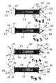
- an exhaust gas recirculation system 1 is shown in the form of a simplified fluid circuit diagram.
- a fluid in particular air or a fuel-air mixture fed.
- the fluid is preferably supplied via a compressor or compressor 4 and optionally a charge air cooler 5 to an internal combustion engine 6, which is also referred to as an internal combustion engine.
- the internal combustion engine 6 is followed by a turbine 7, which, as indicated by a dashed double arrow 8, serves to drive the compressor 4.
- the turbine 7 is followed by a diesel particulate filter 9, for example.
- the power of the internal combustion engine 1 depends on the displacement, the speed and the average fluid pressure, in particular gas pressure from.
- the fluid or fuel-air mixture or the air is completely or partially pre-compressed outside the cylinder of the internal combustion engine.
- the exhaust gases drive the turbine and the compressor.
- the compressor takes over the intake and delivers a pre-compressed fresh gas charge to the engine.
- the intercooler 5 in the charging line dissipates the heat of compression to the ambient air. As a result, the cylinder filling is further improved.
- exhaust gas emitted by the internal combustion engine is branched off.
- the exhaust branched off at the first removal point 11 can be recirculated via a first return line 13, in which a first exhaust gas recirculation valve 14 is arranged.
- the exhaust gas branched off at the second removal point 12 can be returned without cooling via a second return line 16, in which a second exhaust gas recirculation valve 17 is arranged.
- a heat exchanger 18 is connected downstream of the first exhaust gas recirculation valve 14.
- the exhaust branched off at the first removal point 11 and cooled in the heat exchanger 18 can be returned to the internal combustion engine 6 via a heat exchanger return line 20 and via a first return point 21.
- the exhaust branched off at the second removal point 12 can be supplied via the second exhaust gas recirculation valve 17 uncooled via a second return point 22 back to the engine 6.
- the first sampling point 11 is connected between the diesel particulate filter 9 and a counter-pressure valve 24, which serves to build up a back pressure at the first sampling point 11 if necessary.
- the second removal point 12 is arranged between the internal combustion engine 6 and the turbine 7.
- the first return point 21 is arranged between the point 2 and the compressor 4.
- the second return point 22 is arranged between the intercooler 5 and the internal combustion engine 6.
- a third return point 23 is connected downstream of the back pressure valve 24.
- An arrow 25 indicates that the exhaust gas of the internal combustion engine 6 is supplied to a preferably sound-absorbing exhaust system, which may comprise a catalytic converter device.
- the exhaust gas recirculation serves to cool the exhaust gas as far as possible.
- the recirculated exhaust gas no longer takes part in the combustion in the internal combustion engine, but heats up. Overall, the temperature in the internal combustion engine or the engine is lowered by the recirculated exhaust gas. Lower temperatures in the engine can reduce the formation of nitrogen oxides, which are heavily dependent on the temperature in the engine.
- a filter 26 may be arranged in the heat exchanger return line 20, a filter 26 may be arranged.
- the heat exchanger 18 comprises according to an essential aspect of the invention, a branch valve 28 which is connected downstream of the first exhaust gas recirculation valve 14.
- the branch valve 28 ensures that both the exhaust branched off at the first removal point 11 and recirculated via the heat exchanger return line 20 and the exhaust branched off at the first removal point 11 and branched off via a heat exchanger branch line 19 first pass through a heat exchanger block 29 of the heat exchanger 18 for heat exchange, as indicated by an arrow 30.
- the heat exchanger 18 can be operated in two different modes.
- the heat exchanger 18 In an exhaust gas recirculation cooling mode, the heat exchanger 18 is preferably operated as an I-flow heat exchanger to control the temperature of the gas flow to reduce the recirculated exhaust gas.
- the gas flow diverted from the recirculated exhaust gas is used to heat the coolant passed through the heat exchanger, particularly in a warm-up phase of the internal combustion engine.
- the branch valve 28 according to the invention allows a simple way the representation of the two modes with only a single heat exchanger.
- the heat exchanger 18 off FIG. 1 can be designed as a simply flowed through heat exchanger 40, which is also referred to as I-flow heat exchanger.
- the heat exchanger 40 comprises a heat exchanger block 42 through which flows simply through a collecting box 43 at one end.
- the collecting box 43 has an inlet connection 44, through which, as indicated by an arrow 45, exhaust gas branched off at the extraction point 11 enters the collecting box 43.
- a collecting box 46 is provided, in which a branch valve 48 is integrated with a valve flap 49.
- the collecting box 46 has two outlet ports 51, 52, through which the exhaust gas flow passed through the heat exchanger block 42 exits depending on the position of the valve flap 49 of the branch valve 48.
- FIG. 2 obstructs the valve flap 49 of the branch valve 48, the outlet nozzle 52, so that, as indicated by arrows 53 and 54, the entire passed through the heat exchanger block 42 volume flow exiting the outlet port 51 to which preferably the heat exchanger return line 20 is connected.
- the heat exchanger branch line 19 is preferably connected.
- the first return line 13 is preferably connected to the inlet connection 44.
- valve flap 49 of the branch valve 48 is in its second extreme position, in which, as indicated by arrows 56 and 57, the entire exhaust gas flow passed through the heat exchanger block 42 exits through the outlet port 52.
- dashed arrow 58 is indicated that in this position of the valve flap 49 no exhaust gas from the outlet port 51 exits.
- a heat exchanger 60 is shown in simplified form with at least one partition wall indicated by a dashed line 61, which divides a heat exchanger block 62 in such a way that it can be flowed through in a U-shape in opposite directions.
- the heat exchanger 60 comprises at one end of the heat exchanger block 62 a collecting box 63 with an inlet port 64 and an outlet port 65, as indicated by arrows.
- a collecting box 66 is provided, in which a branch valve 68 is integrated with a valve flap 69.
- the collecting box 66 comprises a further outlet port 72 through which emerges exhaust gas in dependence on the position of the valve flap 69 of the branch valve 68 or not.
- FIG. 4 closes the valve flap 69 of the branch valve 68 to the other outlet nozzle 72, so that, as indicated by arrows 73, 74 and 75, the heat exchanger block 62 is flowed through in a U-shape.
- the outlet port 72 occurs, as indicated by a dashed arrow 76, no exhaust gas.
- the first return line 13 is preferably connected to the inlet connection 64. At the outlet port 65, the heat exchanger branch line 19 is connected. At the other outlet port 72, the heat exchanger return line 20 is connected.
- valve flap 69 of the branch valve 68 is in a middle position, in which the in FIG. 4 indicated U-shaped flow through the heat exchanger block 62 is interrupted.
- arrows 77, 78, 79 and 80 is in FIG. 5 indicated that the entering through the inlet port 64 exhaust gas flow through the heat exchanger block 62 I-shaped simply and completely exits through the outlet port 72 again.
- dashed arrow 81 is in FIG. 5 hinted that in this Position of the valve flap 69 of the branch valve 68 no exhaust gas through the outlet port 65 exits.
- FIGS. 2 to 5 illustrated extreme positions of the valve flap 49; 69-the branch valve 48; 68 intermediate positions possible, in soft each only a part of the exhaust gas flow supplied through the first return line 13 into the heat exchanger return line 20 and the heat exchanger branch line 19 passes.
Abstract
Description
Die Erfindung betrifft ein Abgasrückführsystem mit einer Brennkraftmaschine, der an einer Entnahmestelle abgezweigtes und über eine Rückführstelle zurückgeführtes Abgas und/oder Ladeluft zugeführt wird, mit einem zwischen der Entnahmestelle und der Rückführstelle angeordneten Wärmetauscher für das zurückgeführte Abgas und/oder die Ladeluft, und mit einem Abgasrückführventil, über das die zurückgeführte Abgas- und/oder Ladeluftmenge regelbar ist.The invention relates to an exhaust gas recirculation system with an internal combustion engine, which is branched off at a sampling point and fed back via a return point exhaust gas and / or charge air, arranged between the removal point and the return point heat exchanger for the recirculated exhaust gas and / or the charge air, and with a Exhaust gas recirculation valve, via which the recirculated exhaust gas and / or charge air quantity can be regulated.
Aus der Übersetzung
Aufgabe der Erfindung ist es, ein Abgasrückführsystem gemäß dem Oberbegriff des Anspruchs 1 zu schaffen, das einfach aufgebaut und kostengünstig herstellbar ist.The object of the invention is to provide an exhaust gas recirculation system according to the preamble of
Die Aufgabe ist bei einem Abgasrückführsystem mit einer Brennkraftmaschine, der an einer Entnahmestelle abgezweigtes und über eine Rückführstelle zurückgeführtes Abgas und/oder Ladeluft zugeführt wird, mit einem zwischen der Entnahmestelle und der Rückführstelle angeordneten Wärmetauscher für das zurückgeführte Abgas und/oder die Ladeluft, und mit einem Abgasrückführventil, über das die zurückgeführte Abgas- und/oder Ladeluftmenge regelbar ist, dadurch gelöst, dass das Abgasrückführventil zwischen die Entnahmestelle und den Wärmetausche geschaltet ist. Über das Abgasrückführventil wird das gesamte an der Entnahmestelle abgezweigte Abgas beziehungsweise die gesamte dort abgezweigte Ladeluft zum Wärmetausch durch den Wärmetauscher geführt.The object is in an exhaust gas recirculation system with an internal combustion engine, which is branched off at a sampling point and fed back via a recirculation exhaust and / or charge air, with a arranged between the sampling point and the return point heat exchanger for the recirculated exhaust gas and / or the charge air, and with an exhaust gas recirculation valve, via which the recirculated exhaust gas and / or charge air quantity can be regulated, achieved in that the exhaust gas recirculation valve is connected between the extraction point and the heat exchanges. About the exhaust gas recirculation valve, the entire exhaust branched off at the extraction point or the entire charge air branched there is passed through the heat exchanger for heat exchange.
Ein bevorzugtes Ausführungsbeispiel des Abgasrückführsystems ist dadurch gekennzeichnet, dass dem Wärmetauscher ein Abzweigventil zugeordnet ist, über welches das an der Entnahmestelle abgezweigte und aus dem Wärmetauscher austretende Abgas und/oder die Ladeluft über die Rückführstelle zurückgeführt oder über eine Abzweigleitung abgeführt wird. Über das Abzweigventil kann das an der Entnahmestelle abgezweigte Abgas und/oder die Ladeluft, zumindest teilweise, zusammen mit dem nicht an der Entnahmestelle abgezweigten Abgas über eine Auspuffanlage, die gegebenenfalls eine Katalysatoreinrichtung umfasst, in die Umgebung abgeführt werden.A preferred embodiment of the exhaust gas recirculation system is characterized in that the heat exchanger is associated with a branch valve, via which the exhausted at the sampling point and exiting the heat exchanger exhaust gas and / or the charge air is returned via the return point or discharged via a branch line. About the branch valve, the branched off at the sampling exhaust and / or the charge air, at least partially, together with the not branched off at the sampling exhaust gas via an exhaust system, which optionally comprises a catalyst device, are discharged into the environment.
Ein weiteres bevorzugtes Ausführungsbeispiel des Abgasrückführsystems ist dadurch gekennzeichnet, dass das an der Entnahmestelle abgezweigte und aus dem Wärmetauscher austretende Abgas und/oder die Ladeluft durch das Abzweigventil ganz oder teilweise über die Rückführstelle zurückgeführt beziehungsweise über die Abzweigleitung abgeführt wird. Der Wärmetauscher kann zum einen in einer Aufwärmphase der Brennkraftmaschine dazu verwendet werden, das an der Entnahmestelle abgezweigte Abgas zur Wärmerückgewinnung zu kühlen. Darüber hinaus kann der Wärmetauscher dazu verwendet werden, das an der Rückführstelle zurückgeführte Abgas zu kühlen, um Wärme zurückzugewinnen.Another preferred embodiment of the exhaust gas recirculation system is characterized in that the branched off at the sampling point and exiting the heat exchanger exhaust gas and / or the charge air through the branch valve is wholly or partially returned via the return point or discharged via the branch line. On the one hand, the heat exchanger can be used in a warm-up phase of the internal combustion engine to cool the waste gas branched off at the removal point for heat recovery. In addition, the heat exchanger may be used to cool the exhaust gas recirculated at the recycle point to recover heat.
Ein weiteres bevorzugtes Ausführungsbeispiel des Abgasrückführsystems ist dadurch gekennzeichnet, dass das Abzweigventil in den Wärmetauscher integriert ist. Alternativ oder zusätzlich kann das Abgasrückführventil in den Wärmetauscher integriert sein.Another preferred embodiment of the exhaust gas recirculation system is characterized in that the branch valve is integrated into the heat exchanger. Alternatively or additionally, the exhaust gas recirculation valve can be integrated in the heat exchanger.
Ein weiteres bevorzugtes Ausführungsbeispiel des Abgasrückführsystems ist dadurch gekennzeichnet, dass das Abzweigventil an einem Ausgang des Wärmetauschers vorgesehen ist. Dadurch wird auf einfache Art und Weise erreicht, dass das gesamte an der Entnahmestelle abgezweigte Abgas zunächst einem Wärmetausch unterzogen wird.A further preferred embodiment of the exhaust gas recirculation system is characterized in that the branch valve is provided at an outlet of the heat exchanger. As a result, it is achieved in a simple manner that the entire exhaust gas branched off at the removal point is first subjected to a heat exchange.
Ein weiteres bevorzugtes Ausführungsbeispiel des Abgasrückführsystems ist dadurch gekennzeichnet, dass der Wärmetauscher nur in einer Richtung von dem an der Entnahmestelle abgezweigten Abgas und/oder der Ladeluft durchströmbar beziehungsweise durchströmt ist. Ein derartiger Wärmetauscher wird auch als 1-Flow-Wärmetauscher bezeichnet.A further preferred exemplary embodiment of the exhaust gas recirculation system is characterized in that the heat exchanger can only be flowed through or flowed through in one direction by the exhaust gas branched off at the removal point and / or by the charge air. Such a heat exchanger is also referred to as a 1-flow heat exchanger.
Ein weiteres bevorzugtes Ausführungsbeispiel des Abgasrückführsystems ist dadurch gekennzeichnet, dass die Abzweigleitung und eine Rückführleitung an ein Ende des Wärmetauschers angeschlossen sind. Das andere von zwei Enden des Wärmetauschers steht vorzugsweise mit der Entnahmestelle für das Abgas und/oder die Ladeluft in Verbindung.Another preferred embodiment of the exhaust gas recirculation system is characterized in that the branch line and a return line are connected to one end of the heat exchanger. The other of two ends of the heat exchanger is preferably in communication with the exhaust gas discharge point and / or the charge air.
Ein weiteres bevorzugtes Ausführungsbeispiel des Abgasrückführsystems ist dadurch gekennzeichnet, dass der Wärmetauscher in entgegengesetzten Richtungen von dem an der Entnahmestelle abgezweigten Abgas und/oder der Ladeluft durchströmbar beziehungsweise durchströmt ist. Ein derartiger Wärmetauscher wird auch als U-Flow-Wärmetauscher bezeichnet.
Ein weiteres bevorzugtes Ausführungsbeispiel des Abgasrückführsystems ist dadurch gekennzeichnet, dass die Abzweigleitung an ein Ende des Wärmetauschers angeschlossen ist, das mit der Entnahmestelle für das Abgas und/oder die Ladeluft in Verbindung steht. Dadurch wird erreicht, dass das an der Entnahmestelle abgezweigte Abgas, das nicht an der Rückführstelle zurückgeführt wird, den Wärmetauscher mehrfach durchströmt. Dadurch kann die Wärmerückgewinnung weiter verbessert werden.A further preferred embodiment of the exhaust gas recirculation system is characterized in that the heat exchanger in opposite directions from the exhaust branched off at the sampling point and / or the charge air can be flowed through or flowed through. Such a heat exchanger is also referred to as a U-flow heat exchanger.
A further preferred embodiment of the exhaust gas recirculation system is characterized in that the branch line is connected to one end of the heat exchanger, which communicates with the removal point for the exhaust gas and / or the charge air. It is thereby achieved that the exhaust branched off at the removal point, which is not returned to the return point, flows through the heat exchanger several times. As a result, the heat recovery can be further improved.
Ein weiteres bevorzugtes Ausführungsbeispiel des Abgasrückführsystems ist dadurch gekennzeichnet, dass an das andere von zwei Enden des Wärmetauschers eine Rückführleitung angeschlossen ist. In der Rückführleitung kann ein Filter angeordnet sein.A further preferred embodiment of the exhaust gas recirculation system is characterized in that a return line is connected to the other of two ends of the heat exchanger. In the return line, a filter may be arranged.
Ein weiteres bevorzugtes Ausführungsbeispiel des Abgasrückführsystems ist dadurch gekennzeichnet, dass der Entnahmestelle ein Gegendruckventil nachgeschaltet ist. Das Gegendruckventil dient dazu, an der Entnahmestelle einen Gegendruck aufzubauen. Dadurch kann die Temperatur des Abgases erhöht und die Wärmerückgewinnung verbessert werden.A further preferred embodiment of the exhaust gas recirculation system is characterized in that the withdrawal point is followed by a back pressure valve. The back pressure valve is used to build up a back pressure at the sampling point. Thereby, the temperature of the exhaust gas can be increased and the heat recovery can be improved.
Ein weiteres bevorzugtes Ausführungsbeispiel des Abgasrückführsystems ist dadurch gekennzeichnet, dass zwischen der Brennkraftmaschine und der Entnahmestelle eine weitere Entnahmestelle vorgesehen ist, die über ein weiteres Abgasrückführventil mit einer weiteren Rückführstelle verbindbar ist, die zwischen der Rückführstelle und der Brennkraftmaschine vorgesehen ist. Dadurch wird auf einfache Art und Weise eine ungekühlte Rückführung von Abgas ermöglicht.A further preferred embodiment of the exhaust gas recirculation system is characterized in that between the internal combustion engine and the removal point, a further removal point is provided which can be connected via a further exhaust gas recirculation valve with a further return point, which is provided between the return point and the internal combustion engine. As a result, an uncooled return of exhaust gas is made possible in a simple manner.
Ein weiteres bevorzugtes Ausführungsbeispiel des Abgasrückführsystems ist dadurch gekennzeichnet, dass zwischen der Rückführstelle und der Brennkraftmaschine ein Verdichter für das Abgas und/oder die Ladeluft vorgesehen ist, der durch eine Turbine angetrieben ist, die zwischen der Brennkraftmaschine und der Entnahmestelle vorgesehen ist. Die weitere Entnahmestelle ist vorzugsweise zwischen der Brennkraftmaschine und der Turbine vorgesehen. Die weitere Rückführstelle ist vorzugsweise zwischen dem Verdichter und der Brennkraftmaschine vorgesehen.
Ein weiteres bevorzugtes Ausführungsbeispiel des Abgasrückführsystems ist dadurch gekennzeichnet, dass ein Ladeluftkühler zwischen den Verdichter und die Brennkraftmaschine geschaltet ist. Die weitere Rückführstelle ist vorzugsweise zwischen dem Ladeluftkühler und der Brennkraftmaschine vorgesehen.A further preferred embodiment of the exhaust gas recirculation system is characterized in that between the return point and the internal combustion engine, a compressor for the exhaust gas and / or the charge air is provided, which is driven by a turbine, which is provided between the internal combustion engine and the removal point. The further removal point is preferably between the internal combustion engine and the turbine intended. The further return point is preferably provided between the compressor and the internal combustion engine.
A further preferred embodiment of the exhaust gas recirculation system is characterized in that a charge air cooler is connected between the compressor and the internal combustion engine. The further return point is preferably provided between the intercooler and the internal combustion engine.
Ein weiteres bevorzugtes Ausführungsbeispiel des Abgasrückführsystems ist dadurch gekennzeichnet, dass der Turbine ein Dieselpartikelfilter nachgeschaltet ist. Der Dieselpartikelfilter ist vorzugsweise zwischen die Turbine und die Entnahmestelle geschaltet.Another preferred embodiment of the exhaust gas recirculation system is characterized in that the turbine is followed by a diesel particulate filter. The diesel particulate filter is preferably connected between the turbine and the extraction point.
Weitere Vorteile, Merkmale und Einzelheiten der Erfindung ergeben sich aus der nachfolgenden Beschreibung, in der unter Bezugnahme auf die Zeichnung verschiedene Ausführungsbeispiele im Einzelnen beschrieben sind. Es zeigen:
Figur 1- eine vereinfachte Darstellung eines erfindungsgemäßen Abgas- rückführsystems mit einer Brennkraftmaschine und einem Wärme- tauscher;
Figur 2- den Wärmetauscher aus
Figur 1 - Figur 3
- den Wärmetauscher aus
Figur 2 Figur 4- den Wärmetauscher aus
Figur 1 - Figur 5
- den Wärmetauscher aus
Figur 4
- FIG. 1
- a simplified representation of an exhaust gas recirculation system according to the invention with an internal combustion engine and a heat exchanger;
- FIG. 2
- the heat exchanger
FIG. 1 in a 1-flow version in an exhaust gas recirculation mode; - FIG. 3
- the heat exchanger
FIG. 2 in a heat recovery mode; - FIG. 4
- the heat exchanger
FIG. 1 in a U-flow version in heat recovery mode and - FIG. 5
- the heat exchanger
FIG. 4 in exhaust gas recirculation mode.
In
Die Leistung der Brennkraftmaschine 1 hängt vom Hubraum, von der Drehzahl und vom mittleren Fluiddruck, insbesondere Gasdruck, ab. Durch eine Aufladung der Brennkraftmaschine 6 kann die Füllung der Brennräume erheblich verbessert und damit die Motorleistung gesteigert werden. Das Fluid beziehungsweise Kraftstoffluftgemisch oder die Luft wird ganz oder teilweise außerhalb des Zylinders der Brennkraftmaschine vorverdichtet. Bei einem Motor mit Abgasturbolader treiben die Abgase die Turbine und diese den Verdichter an. Der Verdichter übernimmt das Ansaugen und liefert dem Motor eine vorverdichtete Frischgasladung. Der Ladeluftkühler 5 in der Ladeleitung führt die Verdichtungswärme an die Umgebungsluft ab. Dadurch wird die Zylinderfüllung weiter verbessert.The power of the
An einer ersten Entnahmestelle 11 und einer zweiten Entnahmestelle 12 wird von der Brennkraftmaschine abgegebenes Abgas abgezweigt. Das an der ersten Entnahmestelle 11 abgezweigte Abgas kann über eine erste Rückführleitung 13, in der ein erstes Abgasrückführventil 14 angeordnet ist, gekühlt zurückgeführt werden. Das an der zweiten Entnahmestelle 12 abgezweigte Abgas kann über eine zweite Rückführleitung 16, in der ein zweites Abgasrückführventil 17 angeordnet ist, ungekühlt zurückgeführt werden.At a
Zur Kühlung des an der ersten Entnahmestelle 11 abgezweigten Abgases ist dem ersten Abgasrückführventil 14 ein Wärmetauscher 18 nachgeschaltet. Das an der ersten Entnahmestelle 11 abgezweigte und in dem Wärmetauscher 18 gekühlte Abgas kann über eine Wärmetauscherrücktührleitung 20 und über eine erste Rückführstelle 21 wieder der Brennkraftmaschine 6 zugeführt werden. Das an der zweiten Entnahmestelle 12 abgezweigte Abgas kann über das zweite Abgasrückführventil 17 ungekühlt über eine zweite Rückführstelle 22 wieder der Brennkraftmaschine 6 zugeführt werden. Die erste Entnahmestelle 11 ist zwischen den Dieselpartikelfilter 9 und ein Gegendruckventil 24 geschaltet, das dazu dient, bei Bedarf einen Gegendruck an der ersten Entnahmestelle 11 aufzubauen. Die zweite Entnahmestelle 12 ist zwischen der Brennkraftmaschine 6 und der Turbine 7 angeordnet. Die erste Rückführstelle 21 ist zwischen der Stelle 2 und dem Verdichter 4 angeordnet. Die zweite Rückführstelle 22 ist zwischen dem Ladeluftkühler 5 und der Brennkraftmaschine 6 angeordnet. Eine dritte Rückführstelle 23 ist dem Gegendruckventil 24 nachgeschaltet. Durch einen Pfeil 25 ist angedeutet, dass das Abgas der Brennkraftmaschine 6 einer vorzugsweise schalldämpfenden Auspuffanlage zugeführt wird, die eine Katalysatoreinrichtung umfassen kann.For cooling the exhaust branched off at the
Die Abgasrückführung dient dazu, das Abgas möglichst weit abzukühlen. Das zurückgeführte Abgas nimmt an der Verbrennung in der Brennkraftmaschine nicht mehr teil, erwärmt sich aber. Insgesamt wird durch das rückgeführte Abgas die Temperatur in der Brennkraftmaschine beziehungsweise dem Motor abgesenkt. Durch niedrigere Temperaturen im Motor kann die Entstehung von Stickoxyden, die stark von der Temperatur im Motor abhängig sind, reduziert werden. In der Wärmetauscherrückführleitung 20 kann ein Filter 26 angeordnet sein.The exhaust gas recirculation serves to cool the exhaust gas as far as possible. The recirculated exhaust gas no longer takes part in the combustion in the internal combustion engine, but heats up. Overall, the temperature in the internal combustion engine or the engine is lowered by the recirculated exhaust gas. Lower temperatures in the engine can reduce the formation of nitrogen oxides, which are heavily dependent on the temperature in the engine. In the heat
Der Wärmetauscher 18 umfasst gemäß einem wesentlichen Aspekt der Erfindung ein Abzweigventil 28, das dem ersten Abgasrückführventil 14 nachgeschaltet ist. Das Abzweigventil 28 sorgt dafür, dass sowohl das an der ersten Entnahmestelle 11 abgezweigte und über die Wärmetauscherrückführleitung 20 zurückgeführte Abgas als auch das an der ersten Entnahmestelle 11 abgezweigte und über eine Wärmetauscherabzweigleitung 19 abgezweigte Abgas zunächst zwecks Wärmetausch durch einen Wärmetauscherblock 29 des Wärmetauschers 18 strömt, wie durch einen Pfeil 30 angedeutet ist.The
Der Wärmetauscher 18 kann in zwei verschiedenen Modi betrieben werden. In einem Abgasrückführkühlmodus wird der Wärmetauscher 18 vorzugsweise als I-Flow-Wärmetauscher betrieben, um die Temperatur der Gasströmung des zurückgeführten Abgases zu reduzieren. In einem Wärmerückgewinnungsmodus wird die von dem zurückgeführten Abgas abgezweigte Gasströmung verwendet, um das durch den Wärmetauscher durchgeführte Kühlmittel zu erwärmen, insbesondere in einer Aufwärmphase der Brennkraftmaschine. Das erfindungsgemäße Abzweigventil 28 ermöglicht auf einfache Art und Weise die Darstellung der beiden Modi mit nur einem einzigen Wärmetauscher.The
In den
In
In
In den
In
An den Eingangsstutzen 64 ist vorzugsweise die erste Rückführleitung 13 angeschlossen. An den Ausgangsstutzen 65 ist die Wärmetauscherabzweigleitung 19 angeschlossen. An den weiteren Ausgangsstutzen 72 ist die Wärmetauscherrückführleitung 20 angeschlossen.The
In
Selbstverständlich sind zusätzlich zu den in den
Of course, in addition to those in the
Claims (15)
Priority Applications (3)
| Application Number | Priority Date | Filing Date | Title |
|---|---|---|---|
| EP09290726.0A EP2302190B1 (en) | 2009-09-25 | 2009-09-25 | Exhaust gas recycling system |
| CN201010501276XA CN102032073A (en) | 2009-09-25 | 2010-09-25 | Exhaust gas recycling system |
| US12/891,396 US8572962B2 (en) | 2009-09-25 | 2010-09-27 | Exhaust gas recirculation system |
Applications Claiming Priority (1)
| Application Number | Priority Date | Filing Date | Title |
|---|---|---|---|
| EP09290726.0A EP2302190B1 (en) | 2009-09-25 | 2009-09-25 | Exhaust gas recycling system |
Publications (2)
| Publication Number | Publication Date |
|---|---|
| EP2302190A1 true EP2302190A1 (en) | 2011-03-30 |
| EP2302190B1 EP2302190B1 (en) | 2013-12-25 |
Family
ID=41600533
Family Applications (1)
| Application Number | Title | Priority Date | Filing Date |
|---|---|---|---|
| EP09290726.0A Not-in-force EP2302190B1 (en) | 2009-09-25 | 2009-09-25 | Exhaust gas recycling system |
Country Status (3)
| Country | Link |
|---|---|
| US (1) | US8572962B2 (en) |
| EP (1) | EP2302190B1 (en) |
| CN (1) | CN102032073A (en) |
Cited By (3)
| Publication number | Priority date | Publication date | Assignee | Title |
|---|---|---|---|---|
| WO2013167823A1 (en) * | 2012-05-09 | 2013-11-14 | Valeo Systemes De Controle Moteur | System for recovering energy in an exhaust gas circuit |
| WO2016079329A1 (en) * | 2014-11-21 | 2016-05-26 | Maha-Aip Gmbh & Co. Kg | Exhaust gas measuring system for measuring combustion exhaust gases |
| WO2018215222A1 (en) * | 2017-05-22 | 2018-11-29 | Pierburg Gmbh | Exhaust gas recirculation device for an internal combustion engine |
Families Citing this family (9)
| Publication number | Priority date | Publication date | Assignee | Title |
|---|---|---|---|---|
| US8661799B2 (en) * | 2010-10-13 | 2014-03-04 | Ford Global Technologies, Llc | Exhaust system for an internal combustion engine |
| US8839518B1 (en) * | 2010-12-16 | 2014-09-23 | Kennieth Neal | EGR cooler and method of rebuilding existing cooler |
| US20140109884A1 (en) * | 2012-10-23 | 2014-04-24 | Daniel E Hornback | Automotive engine coolant and heating system |
| US9631540B2 (en) * | 2014-10-22 | 2017-04-25 | Ford Global Technologies, Llc | Exhaust system and methods for efficient exhaust heat recovery |
| US10184407B2 (en) * | 2016-09-12 | 2019-01-22 | Ford Global Technologies, Llc | Method and system for emissions reduction |
| DE102016218990A1 (en) * | 2016-09-30 | 2018-04-05 | Ford Global Technologies, Llc | Charged internal combustion engine with cooled exhaust gas recirculation |
| CN106499550A (en) * | 2016-11-28 | 2017-03-15 | 哈尔滨工程大学 | A kind of marine low speed EGR cooler for diesel S CO2 circulate bootstrap system |
| US10107213B2 (en) * | 2016-12-01 | 2018-10-23 | Ford Global Technologies, Llc | Method and system for exhaust gas recirculation and heat recovery |
| DE112020006813A5 (en) * | 2020-02-28 | 2022-12-15 | Pierburg Gmbh | Exhaust gas recirculation system for an internal combustion engine and method for controlling such an exhaust gas recirculation system |
Citations (6)
| Publication number | Priority date | Publication date | Assignee | Title |
|---|---|---|---|---|
| EP0913561A2 (en) * | 1997-10-31 | 1999-05-06 | Valeo Thermique Moteur S.A. | Exhaust and recirculation line of the exhaust gas of an internal combustion engine |
| DE10259702A1 (en) | 2001-12-27 | 2003-07-17 | Denso Corp | Exhaust gas purification system for internal combustion engine of vehicle, recirculates portion of purified exhaust gas cooled by hydrothermal heat exchanger, to intake side |
| EP1405995A1 (en) | 2002-10-02 | 2004-04-07 | Ford Global Technologies, Inc., A subsidiary of Ford Motor Company | Motor system with turbocharger and exhaust gas recirculation as well as method for the operation thereof |
| DE10392766T5 (en) | 2002-06-04 | 2005-06-16 | Valeo Thermique Moteur | Exhaust pipe for an internal combustion engine with a thermal control of the exhaust gases |
| FR2892770A1 (en) * | 2005-10-28 | 2007-05-04 | Renault Sas | Internal combustion engine high-pressure Exhaust Gas Recirculation (EGR) system has return pipe connected between inlet valve and cooler by return valve |
| EP2025912A1 (en) * | 2007-07-30 | 2009-02-18 | Peugeot Citroen Automobiles SA | Engine exhaust gas circuit |
Family Cites Families (3)
| Publication number | Priority date | Publication date | Assignee | Title |
|---|---|---|---|---|
| US5927075A (en) * | 1997-06-06 | 1999-07-27 | Turbodyne Systems, Inc. | Method and apparatus for exhaust gas recirculation control and power augmentation in an internal combustion engine |
| JP4089396B2 (en) * | 2002-11-15 | 2008-05-28 | いすゞ自動車株式会社 | EGR system for internal combustion engine with turbocharger |
| WO2007105815A1 (en) * | 2006-03-16 | 2007-09-20 | Toyota Jidosha Kabushiki Kaisha | Exhaust gas heat recovery device |
-
2009
- 2009-09-25 EP EP09290726.0A patent/EP2302190B1/en not_active Not-in-force
-
2010
- 2010-09-25 CN CN201010501276XA patent/CN102032073A/en active Pending
- 2010-09-27 US US12/891,396 patent/US8572962B2/en not_active Expired - Fee Related
Patent Citations (8)
| Publication number | Priority date | Publication date | Assignee | Title |
|---|---|---|---|---|
| EP0913561A2 (en) * | 1997-10-31 | 1999-05-06 | Valeo Thermique Moteur S.A. | Exhaust and recirculation line of the exhaust gas of an internal combustion engine |
| EP0913561B1 (en) | 1997-10-31 | 2003-08-20 | Valeo Thermique Moteur S.A. | Exhaust and recirculation line of the exhaust gas of an internal combustion engine |
| DE69817294T2 (en) | 1997-10-31 | 2004-06-09 | Valeo Thermique Moteur S.A. | Exhaust and exhaust gas recirculation line of an internal combustion engine |
| DE10259702A1 (en) | 2001-12-27 | 2003-07-17 | Denso Corp | Exhaust gas purification system for internal combustion engine of vehicle, recirculates portion of purified exhaust gas cooled by hydrothermal heat exchanger, to intake side |
| DE10392766T5 (en) | 2002-06-04 | 2005-06-16 | Valeo Thermique Moteur | Exhaust pipe for an internal combustion engine with a thermal control of the exhaust gases |
| EP1405995A1 (en) | 2002-10-02 | 2004-04-07 | Ford Global Technologies, Inc., A subsidiary of Ford Motor Company | Motor system with turbocharger and exhaust gas recirculation as well as method for the operation thereof |
| FR2892770A1 (en) * | 2005-10-28 | 2007-05-04 | Renault Sas | Internal combustion engine high-pressure Exhaust Gas Recirculation (EGR) system has return pipe connected between inlet valve and cooler by return valve |
| EP2025912A1 (en) * | 2007-07-30 | 2009-02-18 | Peugeot Citroen Automobiles SA | Engine exhaust gas circuit |
Cited By (3)
| Publication number | Priority date | Publication date | Assignee | Title |
|---|---|---|---|---|
| WO2013167823A1 (en) * | 2012-05-09 | 2013-11-14 | Valeo Systemes De Controle Moteur | System for recovering energy in an exhaust gas circuit |
| WO2016079329A1 (en) * | 2014-11-21 | 2016-05-26 | Maha-Aip Gmbh & Co. Kg | Exhaust gas measuring system for measuring combustion exhaust gases |
| WO2018215222A1 (en) * | 2017-05-22 | 2018-11-29 | Pierburg Gmbh | Exhaust gas recirculation device for an internal combustion engine |
Also Published As
| Publication number | Publication date |
|---|---|
| EP2302190B1 (en) | 2013-12-25 |
| US8572962B2 (en) | 2013-11-05 |
| US20110072808A1 (en) | 2011-03-31 |
| CN102032073A (en) | 2011-04-27 |
Similar Documents
| Publication | Publication Date | Title |
|---|---|---|
| EP2302190B1 (en) | Exhaust gas recycling system | |
| EP1899595B1 (en) | Device for recycling and cooling exhaust gas for an internal combustion engine | |
| DE102008040312B4 (en) | System for controlling condensation in the intake tract of an internal combustion engine | |
| EP1132609B1 (en) | Heat exchanger in an EGR arrangement | |
| DE4240239C2 (en) | Internal combustion engine | |
| DE102012223808B4 (en) | Internal combustion engine with turbocharging and exhaust gas recirculation and method for operating such an internal combustion engine | |
| DE102008044382A1 (en) | Engine with sequential split series turbocharging | |
| WO2008058596A1 (en) | Internal combustion engine with exhaust-gas recirculation | |
| EP1688607A2 (en) | Exhaust gas recirculation system for an internal combustion engine and exhaust gas recirculation system | |
| WO2006029583A1 (en) | Exhaust-gas recirculation device and method for operating an exhaust-gas recirculation device | |
| EP2151570B1 (en) | Exhaust gas recirculation system for a combustion engine | |
| DE102010036946A1 (en) | High pressure exhaust gas recirculation system with heat recovery | |
| WO2008101978A1 (en) | Make-up gas module for a make-up gas installation | |
| DE102007005246A1 (en) | Air supply to automotive piston engine has air pre-heater which is a liquid/gas heat exchanger forming an integral part of an engine cooling system | |
| DE102016212249A1 (en) | Two-stage direct injection internal combustion engine with exhaust aftertreatment and method of operating such an internal combustion engine | |
| DE102010003337A1 (en) | Motor car, has gas recirculation circuit guided from exhaust gas tract to intake tract of engine via radiator and exhaust gas recirculation valve, and another gas recirculation circuit directly guided from exhaust gas tract to intake tract | |
| DE102010003798A1 (en) | Low pressure exhaust gas recirculation system for use in internal combustion engine of motor car, has control element arranged in recirculating pipe that opens downstream of control valve in exhaust pipe | |
| DE19930416A1 (en) | Cooling device for recycled exhaust gas, using combustion air from supercharger to cool exhaust gas return line | |
| DE102018102111A1 (en) | Device and method for exhaust aftertreatment of an internal combustion engine | |
| EP1843033B1 (en) | Exhaust system of an internal combustion engine for a motor vehicle with exhaust gas recirculation | |
| EP2077386B1 (en) | Cylinder head with exhgaust manifold integrated in cylinder head | |
| DE102007019089A1 (en) | Exhaust gas heat exchanger, exhaust gas heat exchanger system, internal combustion engine and method for treating exhaust gases of an internal combustion engine | |
| WO2008058737A1 (en) | Exhaust-gas recirculation device | |
| DE202013103022U1 (en) | Internal combustion engine with cylinder deactivation | |
| EP0904483B1 (en) | Motor vehicle with an internal combustion engine with external exhaust gas recirculation system and heater |
Legal Events
| Date | Code | Title | Description |
|---|---|---|---|
| PUAI | Public reference made under article 153(3) epc to a published international application that has entered the european phase |
Free format text: ORIGINAL CODE: 0009012 |
|
| AK | Designated contracting states |
Kind code of ref document: A1 Designated state(s): AT BE BG CH CY CZ DE DK EE ES FI FR GB GR HR HU IE IS IT LI LT LU LV MC MK MT NL NO PL PT RO SE SI SK SM TR |
|
| AX | Request for extension of the european patent |
Extension state: AL BA RS |
|
| RAP1 | Party data changed (applicant data changed or rights of an application transferred) |
Owner name: BEHR GMBH & CO. KG |
|
| 17P | Request for examination filed |
Effective date: 20110930 |
|
| 17Q | First examination report despatched |
Effective date: 20111103 |
|
| GRAP | Despatch of communication of intention to grant a patent |
Free format text: ORIGINAL CODE: EPIDOSNIGR1 |
|
| INTG | Intention to grant announced |
Effective date: 20130710 |
|
| GRAS | Grant fee paid |
Free format text: ORIGINAL CODE: EPIDOSNIGR3 |
|
| GRAA | (expected) grant |
Free format text: ORIGINAL CODE: 0009210 |
|
| AK | Designated contracting states |
Kind code of ref document: B1 Designated state(s): AT BE BG CH CY CZ DE DK EE ES FI FR GB GR HR HU IE IS IT LI LT LU LV MC MK MT NL NO PL PT RO SE SI SK SM TR |
|
| REG | Reference to a national code |
Ref country code: GB Ref legal event code: FG4D Free format text: NOT ENGLISH |
|
| REG | Reference to a national code |
Ref country code: CH Ref legal event code: EP |
|
| REG | Reference to a national code |
Ref country code: AT Ref legal event code: REF Ref document number: 646795 Country of ref document: AT Kind code of ref document: T Effective date: 20140115 |
|
| REG | Reference to a national code |
Ref country code: IE Ref legal event code: FG4D Free format text: LANGUAGE OF EP DOCUMENT: GERMAN |
|
| REG | Reference to a national code |
Ref country code: DE Ref legal event code: R096 Ref document number: 502009008572 Country of ref document: DE Effective date: 20140220 |
|
| PG25 | Lapsed in a contracting state [announced via postgrant information from national office to epo] |
Ref country code: HR Free format text: LAPSE BECAUSE OF FAILURE TO SUBMIT A TRANSLATION OF THE DESCRIPTION OR TO PAY THE FEE WITHIN THE PRESCRIBED TIME-LIMIT Effective date: 20131225 Ref country code: NO Free format text: LAPSE BECAUSE OF FAILURE TO SUBMIT A TRANSLATION OF THE DESCRIPTION OR TO PAY THE FEE WITHIN THE PRESCRIBED TIME-LIMIT Effective date: 20140325 Ref country code: FI Free format text: LAPSE BECAUSE OF FAILURE TO SUBMIT A TRANSLATION OF THE DESCRIPTION OR TO PAY THE FEE WITHIN THE PRESCRIBED TIME-LIMIT Effective date: 20131225 Ref country code: LT Free format text: LAPSE BECAUSE OF FAILURE TO SUBMIT A TRANSLATION OF THE DESCRIPTION OR TO PAY THE FEE WITHIN THE PRESCRIBED TIME-LIMIT Effective date: 20131225 Ref country code: SE Free format text: LAPSE BECAUSE OF FAILURE TO SUBMIT A TRANSLATION OF THE DESCRIPTION OR TO PAY THE FEE WITHIN THE PRESCRIBED TIME-LIMIT Effective date: 20131225 |
|
| REG | Reference to a national code |
Ref country code: NL Ref legal event code: VDEP Effective date: 20131225 |
|
| REG | Reference to a national code |
Ref country code: LT Ref legal event code: MG4D |
|
| PG25 | Lapsed in a contracting state [announced via postgrant information from national office to epo] |
Ref country code: LV Free format text: LAPSE BECAUSE OF FAILURE TO SUBMIT A TRANSLATION OF THE DESCRIPTION OR TO PAY THE FEE WITHIN THE PRESCRIBED TIME-LIMIT Effective date: 20131225 |
|
| PG25 | Lapsed in a contracting state [announced via postgrant information from national office to epo] |
Ref country code: IS Free format text: LAPSE BECAUSE OF FAILURE TO SUBMIT A TRANSLATION OF THE DESCRIPTION OR TO PAY THE FEE WITHIN THE PRESCRIBED TIME-LIMIT Effective date: 20140425 Ref country code: EE Free format text: LAPSE BECAUSE OF FAILURE TO SUBMIT A TRANSLATION OF THE DESCRIPTION OR TO PAY THE FEE WITHIN THE PRESCRIBED TIME-LIMIT Effective date: 20131225 |
|
| PG25 | Lapsed in a contracting state [announced via postgrant information from national office to epo] |
Ref country code: NL Free format text: LAPSE BECAUSE OF FAILURE TO SUBMIT A TRANSLATION OF THE DESCRIPTION OR TO PAY THE FEE WITHIN THE PRESCRIBED TIME-LIMIT Effective date: 20131225 Ref country code: SK Free format text: LAPSE BECAUSE OF FAILURE TO SUBMIT A TRANSLATION OF THE DESCRIPTION OR TO PAY THE FEE WITHIN THE PRESCRIBED TIME-LIMIT Effective date: 20131225 Ref country code: PT Free format text: LAPSE BECAUSE OF FAILURE TO SUBMIT A TRANSLATION OF THE DESCRIPTION OR TO PAY THE FEE WITHIN THE PRESCRIBED TIME-LIMIT Effective date: 20140428 Ref country code: PL Free format text: LAPSE BECAUSE OF FAILURE TO SUBMIT A TRANSLATION OF THE DESCRIPTION OR TO PAY THE FEE WITHIN THE PRESCRIBED TIME-LIMIT Effective date: 20131225 Ref country code: CZ Free format text: LAPSE BECAUSE OF FAILURE TO SUBMIT A TRANSLATION OF THE DESCRIPTION OR TO PAY THE FEE WITHIN THE PRESCRIBED TIME-LIMIT Effective date: 20131225 Ref country code: ES Free format text: LAPSE BECAUSE OF FAILURE TO SUBMIT A TRANSLATION OF THE DESCRIPTION OR TO PAY THE FEE WITHIN THE PRESCRIBED TIME-LIMIT Effective date: 20131225 Ref country code: CY Free format text: LAPSE BECAUSE OF FAILURE TO SUBMIT A TRANSLATION OF THE DESCRIPTION OR TO PAY THE FEE WITHIN THE PRESCRIBED TIME-LIMIT Effective date: 20131225 Ref country code: RO Free format text: LAPSE BECAUSE OF FAILURE TO SUBMIT A TRANSLATION OF THE DESCRIPTION OR TO PAY THE FEE WITHIN THE PRESCRIBED TIME-LIMIT Effective date: 20131225 |
|
| REG | Reference to a national code |
Ref country code: DE Ref legal event code: R097 Ref document number: 502009008572 Country of ref document: DE |
|
| PG25 | Lapsed in a contracting state [announced via postgrant information from national office to epo] |
Ref country code: DK Free format text: LAPSE BECAUSE OF FAILURE TO SUBMIT A TRANSLATION OF THE DESCRIPTION OR TO PAY THE FEE WITHIN THE PRESCRIBED TIME-LIMIT Effective date: 20131225 |
|
| PLBE | No opposition filed within time limit |
Free format text: ORIGINAL CODE: 0009261 |
|
| STAA | Information on the status of an ep patent application or granted ep patent |
Free format text: STATUS: NO OPPOSITION FILED WITHIN TIME LIMIT |
|
| 26N | No opposition filed |
Effective date: 20140926 |
|
| REG | Reference to a national code |
Ref country code: DE Ref legal event code: R097 Ref document number: 502009008572 Country of ref document: DE Effective date: 20140926 |
|
| REG | Reference to a national code |
Ref country code: DE Ref legal event code: R082 Ref document number: 502009008572 Country of ref document: DE Representative=s name: GRAUEL, ANDREAS, DIPL.-PHYS. DR. RER. NAT., DE |
|
| PG25 | Lapsed in a contracting state [announced via postgrant information from national office to epo] |
Ref country code: MC Free format text: LAPSE BECAUSE OF FAILURE TO SUBMIT A TRANSLATION OF THE DESCRIPTION OR TO PAY THE FEE WITHIN THE PRESCRIBED TIME-LIMIT Effective date: 20131225 Ref country code: LU Free format text: LAPSE BECAUSE OF FAILURE TO SUBMIT A TRANSLATION OF THE DESCRIPTION OR TO PAY THE FEE WITHIN THE PRESCRIBED TIME-LIMIT Effective date: 20140925 |
|
| REG | Reference to a national code |
Ref country code: DE Ref legal event code: R081 Ref document number: 502009008572 Country of ref document: DE Owner name: MAHLE INTERNATIONAL GMBH, DE Free format text: FORMER OWNER: BEHR GMBH & CO. KG, 70469 STUTTGART, DE Effective date: 20150324 Ref country code: DE Ref legal event code: R082 Ref document number: 502009008572 Country of ref document: DE Representative=s name: GRAUEL, ANDREAS, DIPL.-PHYS. DR. RER. NAT., DE Effective date: 20150324 Ref country code: CH Ref legal event code: PL |
|
| GBPC | Gb: european patent ceased through non-payment of renewal fee |
Effective date: 20140925 |
|
| PG25 | Lapsed in a contracting state [announced via postgrant information from national office to epo] |
Ref country code: SI Free format text: LAPSE BECAUSE OF FAILURE TO SUBMIT A TRANSLATION OF THE DESCRIPTION OR TO PAY THE FEE WITHIN THE PRESCRIBED TIME-LIMIT Effective date: 20131225 |
|
| REG | Reference to a national code |
Ref country code: IE Ref legal event code: MM4A |
|
| PG25 | Lapsed in a contracting state [announced via postgrant information from national office to epo] |
Ref country code: BE Free format text: LAPSE BECAUSE OF NON-PAYMENT OF DUE FEES Effective date: 20140930 |
|
| PG25 | Lapsed in a contracting state [announced via postgrant information from national office to epo] |
Ref country code: LI Free format text: LAPSE BECAUSE OF NON-PAYMENT OF DUE FEES Effective date: 20140930 Ref country code: GB Free format text: LAPSE BECAUSE OF NON-PAYMENT OF DUE FEES Effective date: 20140925 Ref country code: CH Free format text: LAPSE BECAUSE OF NON-PAYMENT OF DUE FEES Effective date: 20140930 |
|
| PG25 | Lapsed in a contracting state [announced via postgrant information from national office to epo] |
Ref country code: IE Free format text: LAPSE BECAUSE OF NON-PAYMENT OF DUE FEES Effective date: 20140925 |
|
| REG | Reference to a national code |
Ref country code: AT Ref legal event code: MM01 Ref document number: 646795 Country of ref document: AT Kind code of ref document: T Effective date: 20140925 |
|
| PG25 | Lapsed in a contracting state [announced via postgrant information from national office to epo] |
Ref country code: AT Free format text: LAPSE BECAUSE OF NON-PAYMENT OF DUE FEES Effective date: 20140925 |
|
| PG25 | Lapsed in a contracting state [announced via postgrant information from national office to epo] |
Ref country code: SM Free format text: LAPSE BECAUSE OF FAILURE TO SUBMIT A TRANSLATION OF THE DESCRIPTION OR TO PAY THE FEE WITHIN THE PRESCRIBED TIME-LIMIT Effective date: 20131225 |
|
| PG25 | Lapsed in a contracting state [announced via postgrant information from national office to epo] |
Ref country code: IT Free format text: LAPSE BECAUSE OF FAILURE TO SUBMIT A TRANSLATION OF THE DESCRIPTION OR TO PAY THE FEE WITHIN THE PRESCRIBED TIME-LIMIT Effective date: 20131225 Ref country code: MT Free format text: LAPSE BECAUSE OF FAILURE TO SUBMIT A TRANSLATION OF THE DESCRIPTION OR TO PAY THE FEE WITHIN THE PRESCRIBED TIME-LIMIT Effective date: 20131225 Ref country code: GR Free format text: LAPSE BECAUSE OF FAILURE TO SUBMIT A TRANSLATION OF THE DESCRIPTION OR TO PAY THE FEE WITHIN THE PRESCRIBED TIME-LIMIT Effective date: 20140326 Ref country code: BG Free format text: LAPSE BECAUSE OF FAILURE TO SUBMIT A TRANSLATION OF THE DESCRIPTION OR TO PAY THE FEE WITHIN THE PRESCRIBED TIME-LIMIT Effective date: 20131225 |
|
| PG25 | Lapsed in a contracting state [announced via postgrant information from national office to epo] |
Ref country code: TR Free format text: LAPSE BECAUSE OF FAILURE TO SUBMIT A TRANSLATION OF THE DESCRIPTION OR TO PAY THE FEE WITHIN THE PRESCRIBED TIME-LIMIT Effective date: 20131225 Ref country code: HU Free format text: LAPSE BECAUSE OF FAILURE TO SUBMIT A TRANSLATION OF THE DESCRIPTION OR TO PAY THE FEE WITHIN THE PRESCRIBED TIME-LIMIT; INVALID AB INITIO Effective date: 20090925 |
|
| REG | Reference to a national code |
Ref country code: FR Ref legal event code: PLFP Year of fee payment: 8 |
|
| REG | Reference to a national code |
Ref country code: FR Ref legal event code: PLFP Year of fee payment: 9 |
|
| PG25 | Lapsed in a contracting state [announced via postgrant information from national office to epo] |
Ref country code: MK Free format text: LAPSE BECAUSE OF FAILURE TO SUBMIT A TRANSLATION OF THE DESCRIPTION OR TO PAY THE FEE WITHIN THE PRESCRIBED TIME-LIMIT Effective date: 20131225 |
|
| REG | Reference to a national code |
Ref country code: FR Ref legal event code: PLFP Year of fee payment: 10 |
|
| PGFP | Annual fee paid to national office [announced via postgrant information from national office to epo] |
Ref country code: DE Payment date: 20181001 Year of fee payment: 10 |
|
| PGFP | Annual fee paid to national office [announced via postgrant information from national office to epo] |
Ref country code: FR Payment date: 20190925 Year of fee payment: 11 |
|
| REG | Reference to a national code |
Ref country code: DE Ref legal event code: R119 Ref document number: 502009008572 Country of ref document: DE |
|
| PG25 | Lapsed in a contracting state [announced via postgrant information from national office to epo] |
Ref country code: DE Free format text: LAPSE BECAUSE OF NON-PAYMENT OF DUE FEES Effective date: 20200401 |
|
| PG25 | Lapsed in a contracting state [announced via postgrant information from national office to epo] |
Ref country code: FR Free format text: LAPSE BECAUSE OF NON-PAYMENT OF DUE FEES Effective date: 20200930 |