EP2302190A1 - Système de refoulement des gaz d'échappement - Google Patents
Système de refoulement des gaz d'échappement Download PDFInfo
- Publication number
- EP2302190A1 EP2302190A1 EP09290726A EP09290726A EP2302190A1 EP 2302190 A1 EP2302190 A1 EP 2302190A1 EP 09290726 A EP09290726 A EP 09290726A EP 09290726 A EP09290726 A EP 09290726A EP 2302190 A1 EP2302190 A1 EP 2302190A1
- Authority
- EP
- European Patent Office
- Prior art keywords
- exhaust gas
- heat exchanger
- gas recirculation
- point
- recirculation system
- Prior art date
- Legal status (The legal status is an assumption and is not a legal conclusion. Google has not performed a legal analysis and makes no representation as to the accuracy of the status listed.)
- Granted
Links
Images

Classifications
-
- F—MECHANICAL ENGINEERING; LIGHTING; HEATING; WEAPONS; BLASTING
- F02—COMBUSTION ENGINES; HOT-GAS OR COMBUSTION-PRODUCT ENGINE PLANTS
- F02M—SUPPLYING COMBUSTION ENGINES IN GENERAL WITH COMBUSTIBLE MIXTURES OR CONSTITUENTS THEREOF
- F02M26/00—Engine-pertinent apparatus for adding exhaust gases to combustion-air, main fuel or fuel-air mixture, e.g. by exhaust gas recirculation [EGR] systems
- F02M26/02—EGR systems specially adapted for supercharged engines
- F02M26/04—EGR systems specially adapted for supercharged engines with a single turbocharger
- F02M26/07—Mixed pressure loops, i.e. wherein recirculated exhaust gas is either taken out upstream of the turbine and reintroduced upstream of the compressor, or is taken out downstream of the turbine and reintroduced downstream of the compressor
-
- F—MECHANICAL ENGINEERING; LIGHTING; HEATING; WEAPONS; BLASTING
- F02—COMBUSTION ENGINES; HOT-GAS OR COMBUSTION-PRODUCT ENGINE PLANTS
- F02M—SUPPLYING COMBUSTION ENGINES IN GENERAL WITH COMBUSTIBLE MIXTURES OR CONSTITUENTS THEREOF
- F02M26/00—Engine-pertinent apparatus for adding exhaust gases to combustion-air, main fuel or fuel-air mixture, e.g. by exhaust gas recirculation [EGR] systems
- F02M26/13—Arrangement or layout of EGR passages, e.g. in relation to specific engine parts or for incorporation of accessories
- F02M26/22—Arrangement or layout of EGR passages, e.g. in relation to specific engine parts or for incorporation of accessories with coolers in the recirculation passage
- F02M26/33—Arrangement or layout of EGR passages, e.g. in relation to specific engine parts or for incorporation of accessories with coolers in the recirculation passage controlling the temperature of the recirculated gases
-
- Y—GENERAL TAGGING OF NEW TECHNOLOGICAL DEVELOPMENTS; GENERAL TAGGING OF CROSS-SECTIONAL TECHNOLOGIES SPANNING OVER SEVERAL SECTIONS OF THE IPC; TECHNICAL SUBJECTS COVERED BY FORMER USPC CROSS-REFERENCE ART COLLECTIONS [XRACs] AND DIGESTS
- Y02—TECHNOLOGIES OR APPLICATIONS FOR MITIGATION OR ADAPTATION AGAINST CLIMATE CHANGE
- Y02T—CLIMATE CHANGE MITIGATION TECHNOLOGIES RELATED TO TRANSPORTATION
- Y02T10/00—Road transport of goods or passengers
- Y02T10/10—Internal combustion engine [ICE] based vehicles
- Y02T10/12—Improving ICE efficiencies
Definitions
- the invention relates to an exhaust gas recirculation system with an internal combustion engine, which is branched off at a sampling point and fed back via a return point exhaust gas and / or charge air, arranged between the removal point and the return point heat exchanger for the recirculated exhaust gas and / or the charge air, and with a Exhaust gas recirculation valve, via which the recirculated exhaust gas and / or charge air quantity can be regulated.
- an exhaust gas recirculation line is known with a heat exchanger arranged between an engine and a catalyst pot in series with constricting means for generating a back pressure, the heat exchanger flow being upwardly from the constricting means.
- an exhaust gas recirculation valve is connected downstream of the heat exchanger.
- a throttle plate is connected in parallel to the heat exchanger.
- a heat exchanger is interposed between an exhaust catalyst pot and a catalytic element.
- German patent application DE 102 59 702 A1 is an exhaust system for a heat engine with a waste heat recovery area for recovering heat from the exhaust gas and for transferring the recovered heat to a heat medium disposed in the exhaust pipe.
- a burner is provided in the exhaust pipe, which is also referred to as Combuster.
- the object of the invention is to provide an exhaust gas recirculation system according to the preamble of claim 1, which is simple in construction and inexpensive to produce.
- the object is in an exhaust gas recirculation system with an internal combustion engine, which is branched off at a sampling point and fed back via a recirculation exhaust and / or charge air, with a arranged between the sampling point and the return point heat exchanger for the recirculated exhaust gas and / or the charge air, and with an exhaust gas recirculation valve, via which the recirculated exhaust gas and / or charge air quantity can be regulated, achieved in that the exhaust gas recirculation valve is connected between the extraction point and the heat exchanges.
- the entire exhaust branched off at the extraction point or the entire charge air branched there is passed through the heat exchanger for heat exchange.
- a preferred embodiment of the exhaust gas recirculation system is characterized in that the heat exchanger is associated with a branch valve, via which the exhausted at the sampling point and exiting the heat exchanger exhaust gas and / or the charge air is returned via the return point or discharged via a branch line.
- the branch valve the branched off at the sampling exhaust and / or the charge air, at least partially, together with the not branched off at the sampling exhaust gas via an exhaust system, which optionally comprises a catalyst device, are discharged into the environment.
- Another preferred embodiment of the exhaust gas recirculation system is characterized in that the branched off at the sampling point and exiting the heat exchanger exhaust gas and / or the charge air through the branch valve is wholly or partially returned via the return point or discharged via the branch line.
- the heat exchanger can be used in a warm-up phase of the internal combustion engine to cool the waste gas branched off at the removal point for heat recovery.
- the heat exchanger may be used to cool the exhaust gas recirculated at the recycle point to recover heat.
- Another preferred embodiment of the exhaust gas recirculation system is characterized in that the branch valve is integrated into the heat exchanger.
- the exhaust gas recirculation valve can be integrated in the heat exchanger.
- a further preferred embodiment of the exhaust gas recirculation system is characterized in that the branch valve is provided at an outlet of the heat exchanger.
- a further preferred exemplary embodiment of the exhaust gas recirculation system is characterized in that the heat exchanger can only be flowed through or flowed through in one direction by the exhaust gas branched off at the removal point and / or by the charge air.
- a heat exchanger is also referred to as a 1-flow heat exchanger.
- Another preferred embodiment of the exhaust gas recirculation system is characterized in that the branch line and a return line are connected to one end of the heat exchanger.
- the other of two ends of the heat exchanger is preferably in communication with the exhaust gas discharge point and / or the charge air.
- a further preferred embodiment of the exhaust gas recirculation system is characterized in that the heat exchanger in opposite directions from the exhaust branched off at the sampling point and / or the charge air can be flowed through or flowed through. Such a heat exchanger is also referred to as a U-flow heat exchanger.
- a further preferred embodiment of the exhaust gas recirculation system is characterized in that the branch line is connected to one end of the heat exchanger, which communicates with the removal point for the exhaust gas and / or the charge air. It is thereby achieved that the exhaust branched off at the removal point, which is not returned to the return point, flows through the heat exchanger several times. As a result, the heat recovery can be further improved.
- a further preferred embodiment of the exhaust gas recirculation system is characterized in that a return line is connected to the other of two ends of the heat exchanger. In the return line, a filter may be arranged.
- a further preferred embodiment of the exhaust gas recirculation system is characterized in that the withdrawal point is followed by a back pressure valve.
- the back pressure valve is used to build up a back pressure at the sampling point. Thereby, the temperature of the exhaust gas can be increased and the heat recovery can be improved.
- a further preferred embodiment of the exhaust gas recirculation system is characterized in that between the internal combustion engine and the removal point, a further removal point is provided which can be connected via a further exhaust gas recirculation valve with a further return point, which is provided between the return point and the internal combustion engine.
- a further preferred embodiment of the exhaust gas recirculation system is characterized in that between the return point and the internal combustion engine, a compressor for the exhaust gas and / or the charge air is provided, which is driven by a turbine, which is provided between the internal combustion engine and the removal point.
- the further removal point is preferably between the internal combustion engine and the turbine intended.
- the further return point is preferably provided between the compressor and the internal combustion engine.
- a further preferred embodiment of the exhaust gas recirculation system is characterized in that a charge air cooler is connected between the compressor and the internal combustion engine.
- the further return point is preferably provided between the intercooler and the internal combustion engine.
- Another preferred embodiment of the exhaust gas recirculation system is characterized in that the turbine is followed by a diesel particulate filter.
- the diesel particulate filter is preferably connected between the turbine and the extraction point.
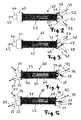
- an exhaust gas recirculation system 1 is shown in the form of a simplified fluid circuit diagram.
- a fluid in particular air or a fuel-air mixture fed.
- the fluid is preferably supplied via a compressor or compressor 4 and optionally a charge air cooler 5 to an internal combustion engine 6, which is also referred to as an internal combustion engine.
- the internal combustion engine 6 is followed by a turbine 7, which, as indicated by a dashed double arrow 8, serves to drive the compressor 4.
- the turbine 7 is followed by a diesel particulate filter 9, for example.
- the power of the internal combustion engine 1 depends on the displacement, the speed and the average fluid pressure, in particular gas pressure from.
- the fluid or fuel-air mixture or the air is completely or partially pre-compressed outside the cylinder of the internal combustion engine.
- the exhaust gases drive the turbine and the compressor.
- the compressor takes over the intake and delivers a pre-compressed fresh gas charge to the engine.
- the intercooler 5 in the charging line dissipates the heat of compression to the ambient air. As a result, the cylinder filling is further improved.
- exhaust gas emitted by the internal combustion engine is branched off.
- the exhaust branched off at the first removal point 11 can be recirculated via a first return line 13, in which a first exhaust gas recirculation valve 14 is arranged.
- the exhaust gas branched off at the second removal point 12 can be returned without cooling via a second return line 16, in which a second exhaust gas recirculation valve 17 is arranged.
- a heat exchanger 18 is connected downstream of the first exhaust gas recirculation valve 14.
- the exhaust branched off at the first removal point 11 and cooled in the heat exchanger 18 can be returned to the internal combustion engine 6 via a heat exchanger return line 20 and via a first return point 21.
- the exhaust branched off at the second removal point 12 can be supplied via the second exhaust gas recirculation valve 17 uncooled via a second return point 22 back to the engine 6.
- the first sampling point 11 is connected between the diesel particulate filter 9 and a counter-pressure valve 24, which serves to build up a back pressure at the first sampling point 11 if necessary.
- the second removal point 12 is arranged between the internal combustion engine 6 and the turbine 7.
- the first return point 21 is arranged between the point 2 and the compressor 4.
- the second return point 22 is arranged between the intercooler 5 and the internal combustion engine 6.
- a third return point 23 is connected downstream of the back pressure valve 24.
- An arrow 25 indicates that the exhaust gas of the internal combustion engine 6 is supplied to a preferably sound-absorbing exhaust system, which may comprise a catalytic converter device.
- the exhaust gas recirculation serves to cool the exhaust gas as far as possible.
- the recirculated exhaust gas no longer takes part in the combustion in the internal combustion engine, but heats up. Overall, the temperature in the internal combustion engine or the engine is lowered by the recirculated exhaust gas. Lower temperatures in the engine can reduce the formation of nitrogen oxides, which are heavily dependent on the temperature in the engine.
- a filter 26 may be arranged in the heat exchanger return line 20, a filter 26 may be arranged.
- the heat exchanger 18 comprises according to an essential aspect of the invention, a branch valve 28 which is connected downstream of the first exhaust gas recirculation valve 14.
- the branch valve 28 ensures that both the exhaust branched off at the first removal point 11 and recirculated via the heat exchanger return line 20 and the exhaust branched off at the first removal point 11 and branched off via a heat exchanger branch line 19 first pass through a heat exchanger block 29 of the heat exchanger 18 for heat exchange, as indicated by an arrow 30.
- the heat exchanger 18 can be operated in two different modes.
- the heat exchanger 18 In an exhaust gas recirculation cooling mode, the heat exchanger 18 is preferably operated as an I-flow heat exchanger to control the temperature of the gas flow to reduce the recirculated exhaust gas.
- the gas flow diverted from the recirculated exhaust gas is used to heat the coolant passed through the heat exchanger, particularly in a warm-up phase of the internal combustion engine.
- the branch valve 28 according to the invention allows a simple way the representation of the two modes with only a single heat exchanger.
- the heat exchanger 18 off FIG. 1 can be designed as a simply flowed through heat exchanger 40, which is also referred to as I-flow heat exchanger.
- the heat exchanger 40 comprises a heat exchanger block 42 through which flows simply through a collecting box 43 at one end.
- the collecting box 43 has an inlet connection 44, through which, as indicated by an arrow 45, exhaust gas branched off at the extraction point 11 enters the collecting box 43.
- a collecting box 46 is provided, in which a branch valve 48 is integrated with a valve flap 49.
- the collecting box 46 has two outlet ports 51, 52, through which the exhaust gas flow passed through the heat exchanger block 42 exits depending on the position of the valve flap 49 of the branch valve 48.
- FIG. 2 obstructs the valve flap 49 of the branch valve 48, the outlet nozzle 52, so that, as indicated by arrows 53 and 54, the entire passed through the heat exchanger block 42 volume flow exiting the outlet port 51 to which preferably the heat exchanger return line 20 is connected.
- the heat exchanger branch line 19 is preferably connected.
- the first return line 13 is preferably connected to the inlet connection 44.
- valve flap 49 of the branch valve 48 is in its second extreme position, in which, as indicated by arrows 56 and 57, the entire exhaust gas flow passed through the heat exchanger block 42 exits through the outlet port 52.
- dashed arrow 58 is indicated that in this position of the valve flap 49 no exhaust gas from the outlet port 51 exits.
- a heat exchanger 60 is shown in simplified form with at least one partition wall indicated by a dashed line 61, which divides a heat exchanger block 62 in such a way that it can be flowed through in a U-shape in opposite directions.
- the heat exchanger 60 comprises at one end of the heat exchanger block 62 a collecting box 63 with an inlet port 64 and an outlet port 65, as indicated by arrows.
- a collecting box 66 is provided, in which a branch valve 68 is integrated with a valve flap 69.
- the collecting box 66 comprises a further outlet port 72 through which emerges exhaust gas in dependence on the position of the valve flap 69 of the branch valve 68 or not.
- FIG. 4 closes the valve flap 69 of the branch valve 68 to the other outlet nozzle 72, so that, as indicated by arrows 73, 74 and 75, the heat exchanger block 62 is flowed through in a U-shape.
- the outlet port 72 occurs, as indicated by a dashed arrow 76, no exhaust gas.
- the first return line 13 is preferably connected to the inlet connection 64. At the outlet port 65, the heat exchanger branch line 19 is connected. At the other outlet port 72, the heat exchanger return line 20 is connected.
- valve flap 69 of the branch valve 68 is in a middle position, in which the in FIG. 4 indicated U-shaped flow through the heat exchanger block 62 is interrupted.
- arrows 77, 78, 79 and 80 is in FIG. 5 indicated that the entering through the inlet port 64 exhaust gas flow through the heat exchanger block 62 I-shaped simply and completely exits through the outlet port 72 again.
- dashed arrow 81 is in FIG. 5 hinted that in this Position of the valve flap 69 of the branch valve 68 no exhaust gas through the outlet port 65 exits.
- FIGS. 2 to 5 illustrated extreme positions of the valve flap 49; 69-the branch valve 48; 68 intermediate positions possible, in soft each only a part of the exhaust gas flow supplied through the first return line 13 into the heat exchanger return line 20 and the heat exchanger branch line 19 passes.
Landscapes
- Engineering & Computer Science (AREA)
- Chemical & Material Sciences (AREA)
- Combustion & Propulsion (AREA)
- Mechanical Engineering (AREA)
- General Engineering & Computer Science (AREA)
- Exhaust-Gas Circulating Devices (AREA)
Priority Applications (3)
| Application Number | Priority Date | Filing Date | Title |
|---|---|---|---|
| EP09290726.0A EP2302190B1 (fr) | 2009-09-25 | 2009-09-25 | Système de refoulement des gaz d'échappement |
| CN201010501276XA CN102032073A (zh) | 2009-09-25 | 2010-09-25 | 废气再循环系统 |
| US12/891,396 US8572962B2 (en) | 2009-09-25 | 2010-09-27 | Exhaust gas recirculation system |
Applications Claiming Priority (1)
| Application Number | Priority Date | Filing Date | Title |
|---|---|---|---|
| EP09290726.0A EP2302190B1 (fr) | 2009-09-25 | 2009-09-25 | Système de refoulement des gaz d'échappement |
Publications (2)
| Publication Number | Publication Date |
|---|---|
| EP2302190A1 true EP2302190A1 (fr) | 2011-03-30 |
| EP2302190B1 EP2302190B1 (fr) | 2013-12-25 |
Family
ID=41600533
Family Applications (1)
| Application Number | Title | Priority Date | Filing Date |
|---|---|---|---|
| EP09290726.0A Not-in-force EP2302190B1 (fr) | 2009-09-25 | 2009-09-25 | Système de refoulement des gaz d'échappement |
Country Status (3)
| Country | Link |
|---|---|
| US (1) | US8572962B2 (fr) |
| EP (1) | EP2302190B1 (fr) |
| CN (1) | CN102032073A (fr) |
Cited By (3)
| Publication number | Priority date | Publication date | Assignee | Title |
|---|---|---|---|---|
| WO2013167823A1 (fr) * | 2012-05-09 | 2013-11-14 | Valeo Systemes De Controle Moteur | Système de récupération d'énergie dans un circuit de gaz d'échappement |
| WO2016079329A1 (fr) * | 2014-11-21 | 2016-05-26 | Maha-Aip Gmbh & Co. Kg | Installation de mesure de gaz d'échappement de combustion |
| WO2018215222A1 (fr) * | 2017-05-22 | 2018-11-29 | Pierburg Gmbh | Dispositif de recyclage des gaz d'échappement pour un moteur à combustion interne |
Families Citing this family (9)
| Publication number | Priority date | Publication date | Assignee | Title |
|---|---|---|---|---|
| US8661799B2 (en) * | 2010-10-13 | 2014-03-04 | Ford Global Technologies, Llc | Exhaust system for an internal combustion engine |
| US8839518B1 (en) * | 2010-12-16 | 2014-09-23 | Kennieth Neal | EGR cooler and method of rebuilding existing cooler |
| US20140109884A1 (en) * | 2012-10-23 | 2014-04-24 | Daniel E Hornback | Automotive engine coolant and heating system |
| US9631540B2 (en) * | 2014-10-22 | 2017-04-25 | Ford Global Technologies, Llc | Exhaust system and methods for efficient exhaust heat recovery |
| US10184407B2 (en) * | 2016-09-12 | 2019-01-22 | Ford Global Technologies, Llc | Method and system for emissions reduction |
| DE102016218990A1 (de) * | 2016-09-30 | 2018-04-05 | Ford Global Technologies, Llc | Aufgeladene Brennkraftmaschine mit gekühlter Abgasrückführung |
| CN106499550A (zh) * | 2016-11-28 | 2017-03-15 | 哈尔滨工程大学 | 一种船舶低速柴油机egr冷却器s‑co2循环余热利用系统 |
| US10107213B2 (en) * | 2016-12-01 | 2018-10-23 | Ford Global Technologies, Llc | Method and system for exhaust gas recirculation and heat recovery |
| DE112020006813A5 (de) * | 2020-02-28 | 2022-12-15 | Pierburg Gmbh | Abgasrückführsystem für eine Verbrennungskraftmaschine sowie Verfahren zur Regelung eines derartigen Abgasrückführsystems |
Citations (6)
| Publication number | Priority date | Publication date | Assignee | Title |
|---|---|---|---|---|
| EP0913561A2 (fr) * | 1997-10-31 | 1999-05-06 | Valeo Thermique Moteur S.A. | Ligne d'échappement et de recirculation des gaz pour moteur de véhicule automobile |
| DE10259702A1 (de) | 2001-12-27 | 2003-07-17 | Denso Corp | Abgassystem für einen Wärmemotor |
| EP1405995A1 (fr) | 2002-10-02 | 2004-04-07 | Ford Global Technologies, Inc., A subsidiary of Ford Motor Company | Moteur suralimenté par un turbocompresseur à recirculation de gaz d'échappement ainsi que le procédé de fonctionnement de celui-ci |
| DE10392766T5 (de) | 2002-06-04 | 2005-06-16 | Valeo Thermique Moteur | Abgasleitung für einen Brennkraftmotor mit einer thermischen Regelung der Abgase |
| FR2892770A1 (fr) * | 2005-10-28 | 2007-05-04 | Renault Sas | Dispositif de recirculation controlee des gaz brules d'un circuit egr a haute pression |
| EP2025912A1 (fr) * | 2007-07-30 | 2009-02-18 | Peugeot Citroen Automobiles SA | Circuit des gaz d'échappement d'un moteur |
Family Cites Families (3)
| Publication number | Priority date | Publication date | Assignee | Title |
|---|---|---|---|---|
| US5927075A (en) * | 1997-06-06 | 1999-07-27 | Turbodyne Systems, Inc. | Method and apparatus for exhaust gas recirculation control and power augmentation in an internal combustion engine |
| JP4089396B2 (ja) * | 2002-11-15 | 2008-05-28 | いすゞ自動車株式会社 | ターボチャージャーを備えた内燃機関のegrシステム |
| EP2002093B1 (fr) * | 2006-03-16 | 2011-09-14 | Toyota Jidosha Kabushiki Kaisha | Dispositif de recuperation de chaleur des gaz d'echappement |
-
2009
- 2009-09-25 EP EP09290726.0A patent/EP2302190B1/fr not_active Not-in-force
-
2010
- 2010-09-25 CN CN201010501276XA patent/CN102032073A/zh active Pending
- 2010-09-27 US US12/891,396 patent/US8572962B2/en not_active Expired - Fee Related
Patent Citations (8)
| Publication number | Priority date | Publication date | Assignee | Title |
|---|---|---|---|---|
| EP0913561A2 (fr) * | 1997-10-31 | 1999-05-06 | Valeo Thermique Moteur S.A. | Ligne d'échappement et de recirculation des gaz pour moteur de véhicule automobile |
| EP0913561B1 (fr) | 1997-10-31 | 2003-08-20 | Valeo Thermique Moteur S.A. | Ligne d'échappement et de recirculation des gaz pour moteur de véhicule automobile |
| DE69817294T2 (de) | 1997-10-31 | 2004-06-09 | Valeo Thermique Moteur S.A. | Auspuff- und Abgasrückführungsleitung einer Brennkraftmaschine |
| DE10259702A1 (de) | 2001-12-27 | 2003-07-17 | Denso Corp | Abgassystem für einen Wärmemotor |
| DE10392766T5 (de) | 2002-06-04 | 2005-06-16 | Valeo Thermique Moteur | Abgasleitung für einen Brennkraftmotor mit einer thermischen Regelung der Abgase |
| EP1405995A1 (fr) | 2002-10-02 | 2004-04-07 | Ford Global Technologies, Inc., A subsidiary of Ford Motor Company | Moteur suralimenté par un turbocompresseur à recirculation de gaz d'échappement ainsi que le procédé de fonctionnement de celui-ci |
| FR2892770A1 (fr) * | 2005-10-28 | 2007-05-04 | Renault Sas | Dispositif de recirculation controlee des gaz brules d'un circuit egr a haute pression |
| EP2025912A1 (fr) * | 2007-07-30 | 2009-02-18 | Peugeot Citroen Automobiles SA | Circuit des gaz d'échappement d'un moteur |
Cited By (3)
| Publication number | Priority date | Publication date | Assignee | Title |
|---|---|---|---|---|
| WO2013167823A1 (fr) * | 2012-05-09 | 2013-11-14 | Valeo Systemes De Controle Moteur | Système de récupération d'énergie dans un circuit de gaz d'échappement |
| WO2016079329A1 (fr) * | 2014-11-21 | 2016-05-26 | Maha-Aip Gmbh & Co. Kg | Installation de mesure de gaz d'échappement de combustion |
| WO2018215222A1 (fr) * | 2017-05-22 | 2018-11-29 | Pierburg Gmbh | Dispositif de recyclage des gaz d'échappement pour un moteur à combustion interne |
Also Published As
| Publication number | Publication date |
|---|---|
| US20110072808A1 (en) | 2011-03-31 |
| CN102032073A (zh) | 2011-04-27 |
| US8572962B2 (en) | 2013-11-05 |
| EP2302190B1 (fr) | 2013-12-25 |
Similar Documents
| Publication | Publication Date | Title |
|---|---|---|
| EP2302190B1 (fr) | Système de refoulement des gaz d'échappement | |
| EP1899595B1 (fr) | Dispositif de recyclage et de refroidissement de gaz d'echappement conçu pour un moteur a combustion interne | |
| DE102008040312B4 (de) | System zum Regeln der Kondensation im Ansaugtrakt eines Verbrennungsmotors | |
| EP1132609B1 (fr) | Echangeur de chaleur disposé dans un dispositif de recirculation de gaz d'échappement | |
| DE4240239C2 (de) | Verbrennungskraftmaschine | |
| DE102012223808B4 (de) | Brennkraftmaschine mit Abgasturboaufladung und Abgasrückführung und Verfahren zum Betreiben einer derartigen Brennkraftmaschine | |
| WO2008058596A1 (fr) | Moteur à combustion interne doté d'un recyclage des gaz d'échappement | |
| EP1688607A2 (fr) | Système de recyclage des gaz d'échappement pour un moteur à combustion interne et système de recyclage des gaz d'échappement | |
| WO2006029583A1 (fr) | Dispositif de retour de gaz d'echappement et procede pour faire fonctionner un dispositif de retour de gaz d'echappement | |
| EP2151570B1 (fr) | Dispositif de recirculation des gaz d'échappement pour un moteur à combustion interne | |
| DE102010036946A1 (de) | Hochdruck-Abgasrückführsystem mit Wärmerückgewinnung | |
| WO2008101978A1 (fr) | Module de gaz frais conçu pour une installation de gaz frais | |
| DE102007005246A1 (de) | Brennkraftmaschine | |
| DE102016212249A1 (de) | Zweistufig aufladbare direkteinspritzende Brennkraftmaschine mit Abgasnachbehandlung und Verfahren zum Betreiben einer derartigen Brennkraftmaschine | |
| DE102010003337A1 (de) | Kraftfahrzeug mit Verbrennungsmotor sowie Verfahren zu dessen Betrieb | |
| DE102010003798A1 (de) | Niederdruck-Abgasrückführsystem mit Wärmerückgewinnung | |
| DE19930416A1 (de) | Kühlvorrichtung für zur Saugseite eines aufgeladenen Verbrennungsmotors rückgeführtes Abgas | |
| DE102018102111A1 (de) | Vorrichtung und Verfahren zur Abgasnachbehandlung eines Verbrennungsmotors | |
| EP1843033B1 (fr) | Système d'échappement d'un moteur à combustion interne pour véhicule automobile doté d'un système de recirculation de gaz d'échappement | |
| EP2077386B1 (fr) | Culasse dotée d'un collecteur de gaz d'échappement intégré dans la culasse | |
| DE102007019089A1 (de) | Abgaswärmetauscher, Abgaswärmetauschersystem, Brennkraftmotor und Verfahren zum Behandeln von Abgasen eines Brennkraftmotors | |
| WO2008058737A1 (fr) | Dispositif de recyclage des gaz d'échappement | |
| DE202013103022U1 (de) | Verbrennungsmotor mit Zylinderabschaltung | |
| EP0904483B1 (fr) | Vehicule automobile a moteur a combustion interne avec recyclage externe des gaz d'echappement et dispositif de chauffage | |
| DE102020208986A1 (de) | Brennkraftmaschine mit Niederdruck-Abgasrückführleitung, zwei Teilsträngen des Frischgasstrangs und Frischgas-Abgas-Wärmetauscher |
Legal Events
| Date | Code | Title | Description |
|---|---|---|---|
| PUAI | Public reference made under article 153(3) epc to a published international application that has entered the european phase |
Free format text: ORIGINAL CODE: 0009012 |
|
| AK | Designated contracting states |
Kind code of ref document: A1 Designated state(s): AT BE BG CH CY CZ DE DK EE ES FI FR GB GR HR HU IE IS IT LI LT LU LV MC MK MT NL NO PL PT RO SE SI SK SM TR |
|
| AX | Request for extension of the european patent |
Extension state: AL BA RS |
|
| RAP1 | Party data changed (applicant data changed or rights of an application transferred) |
Owner name: BEHR GMBH & CO. KG |
|
| 17P | Request for examination filed |
Effective date: 20110930 |
|
| 17Q | First examination report despatched |
Effective date: 20111103 |
|
| GRAP | Despatch of communication of intention to grant a patent |
Free format text: ORIGINAL CODE: EPIDOSNIGR1 |
|
| INTG | Intention to grant announced |
Effective date: 20130710 |
|
| GRAS | Grant fee paid |
Free format text: ORIGINAL CODE: EPIDOSNIGR3 |
|
| GRAA | (expected) grant |
Free format text: ORIGINAL CODE: 0009210 |
|
| AK | Designated contracting states |
Kind code of ref document: B1 Designated state(s): AT BE BG CH CY CZ DE DK EE ES FI FR GB GR HR HU IE IS IT LI LT LU LV MC MK MT NL NO PL PT RO SE SI SK SM TR |
|
| REG | Reference to a national code |
Ref country code: GB Ref legal event code: FG4D Free format text: NOT ENGLISH |
|
| REG | Reference to a national code |
Ref country code: CH Ref legal event code: EP |
|
| REG | Reference to a national code |
Ref country code: AT Ref legal event code: REF Ref document number: 646795 Country of ref document: AT Kind code of ref document: T Effective date: 20140115 |
|
| REG | Reference to a national code |
Ref country code: IE Ref legal event code: FG4D Free format text: LANGUAGE OF EP DOCUMENT: GERMAN |
|
| REG | Reference to a national code |
Ref country code: DE Ref legal event code: R096 Ref document number: 502009008572 Country of ref document: DE Effective date: 20140220 |
|
| PG25 | Lapsed in a contracting state [announced via postgrant information from national office to epo] |
Ref country code: HR Free format text: LAPSE BECAUSE OF FAILURE TO SUBMIT A TRANSLATION OF THE DESCRIPTION OR TO PAY THE FEE WITHIN THE PRESCRIBED TIME-LIMIT Effective date: 20131225 Ref country code: NO Free format text: LAPSE BECAUSE OF FAILURE TO SUBMIT A TRANSLATION OF THE DESCRIPTION OR TO PAY THE FEE WITHIN THE PRESCRIBED TIME-LIMIT Effective date: 20140325 Ref country code: FI Free format text: LAPSE BECAUSE OF FAILURE TO SUBMIT A TRANSLATION OF THE DESCRIPTION OR TO PAY THE FEE WITHIN THE PRESCRIBED TIME-LIMIT Effective date: 20131225 Ref country code: LT Free format text: LAPSE BECAUSE OF FAILURE TO SUBMIT A TRANSLATION OF THE DESCRIPTION OR TO PAY THE FEE WITHIN THE PRESCRIBED TIME-LIMIT Effective date: 20131225 Ref country code: SE Free format text: LAPSE BECAUSE OF FAILURE TO SUBMIT A TRANSLATION OF THE DESCRIPTION OR TO PAY THE FEE WITHIN THE PRESCRIBED TIME-LIMIT Effective date: 20131225 |
|
| REG | Reference to a national code |
Ref country code: NL Ref legal event code: VDEP Effective date: 20131225 |
|
| REG | Reference to a national code |
Ref country code: LT Ref legal event code: MG4D |
|
| PG25 | Lapsed in a contracting state [announced via postgrant information from national office to epo] |
Ref country code: LV Free format text: LAPSE BECAUSE OF FAILURE TO SUBMIT A TRANSLATION OF THE DESCRIPTION OR TO PAY THE FEE WITHIN THE PRESCRIBED TIME-LIMIT Effective date: 20131225 |
|
| PG25 | Lapsed in a contracting state [announced via postgrant information from national office to epo] |
Ref country code: IS Free format text: LAPSE BECAUSE OF FAILURE TO SUBMIT A TRANSLATION OF THE DESCRIPTION OR TO PAY THE FEE WITHIN THE PRESCRIBED TIME-LIMIT Effective date: 20140425 Ref country code: EE Free format text: LAPSE BECAUSE OF FAILURE TO SUBMIT A TRANSLATION OF THE DESCRIPTION OR TO PAY THE FEE WITHIN THE PRESCRIBED TIME-LIMIT Effective date: 20131225 |
|
| PG25 | Lapsed in a contracting state [announced via postgrant information from national office to epo] |
Ref country code: NL Free format text: LAPSE BECAUSE OF FAILURE TO SUBMIT A TRANSLATION OF THE DESCRIPTION OR TO PAY THE FEE WITHIN THE PRESCRIBED TIME-LIMIT Effective date: 20131225 Ref country code: SK Free format text: LAPSE BECAUSE OF FAILURE TO SUBMIT A TRANSLATION OF THE DESCRIPTION OR TO PAY THE FEE WITHIN THE PRESCRIBED TIME-LIMIT Effective date: 20131225 Ref country code: PT Free format text: LAPSE BECAUSE OF FAILURE TO SUBMIT A TRANSLATION OF THE DESCRIPTION OR TO PAY THE FEE WITHIN THE PRESCRIBED TIME-LIMIT Effective date: 20140428 Ref country code: PL Free format text: LAPSE BECAUSE OF FAILURE TO SUBMIT A TRANSLATION OF THE DESCRIPTION OR TO PAY THE FEE WITHIN THE PRESCRIBED TIME-LIMIT Effective date: 20131225 Ref country code: CZ Free format text: LAPSE BECAUSE OF FAILURE TO SUBMIT A TRANSLATION OF THE DESCRIPTION OR TO PAY THE FEE WITHIN THE PRESCRIBED TIME-LIMIT Effective date: 20131225 Ref country code: ES Free format text: LAPSE BECAUSE OF FAILURE TO SUBMIT A TRANSLATION OF THE DESCRIPTION OR TO PAY THE FEE WITHIN THE PRESCRIBED TIME-LIMIT Effective date: 20131225 Ref country code: CY Free format text: LAPSE BECAUSE OF FAILURE TO SUBMIT A TRANSLATION OF THE DESCRIPTION OR TO PAY THE FEE WITHIN THE PRESCRIBED TIME-LIMIT Effective date: 20131225 Ref country code: RO Free format text: LAPSE BECAUSE OF FAILURE TO SUBMIT A TRANSLATION OF THE DESCRIPTION OR TO PAY THE FEE WITHIN THE PRESCRIBED TIME-LIMIT Effective date: 20131225 |
|
| REG | Reference to a national code |
Ref country code: DE Ref legal event code: R097 Ref document number: 502009008572 Country of ref document: DE |
|
| PG25 | Lapsed in a contracting state [announced via postgrant information from national office to epo] |
Ref country code: DK Free format text: LAPSE BECAUSE OF FAILURE TO SUBMIT A TRANSLATION OF THE DESCRIPTION OR TO PAY THE FEE WITHIN THE PRESCRIBED TIME-LIMIT Effective date: 20131225 |
|
| PLBE | No opposition filed within time limit |
Free format text: ORIGINAL CODE: 0009261 |
|
| STAA | Information on the status of an ep patent application or granted ep patent |
Free format text: STATUS: NO OPPOSITION FILED WITHIN TIME LIMIT |
|
| 26N | No opposition filed |
Effective date: 20140926 |
|
| REG | Reference to a national code |
Ref country code: DE Ref legal event code: R097 Ref document number: 502009008572 Country of ref document: DE Effective date: 20140926 |
|
| REG | Reference to a national code |
Ref country code: DE Ref legal event code: R082 Ref document number: 502009008572 Country of ref document: DE Representative=s name: GRAUEL, ANDREAS, DIPL.-PHYS. DR. RER. NAT., DE |
|
| PG25 | Lapsed in a contracting state [announced via postgrant information from national office to epo] |
Ref country code: MC Free format text: LAPSE BECAUSE OF FAILURE TO SUBMIT A TRANSLATION OF THE DESCRIPTION OR TO PAY THE FEE WITHIN THE PRESCRIBED TIME-LIMIT Effective date: 20131225 Ref country code: LU Free format text: LAPSE BECAUSE OF FAILURE TO SUBMIT A TRANSLATION OF THE DESCRIPTION OR TO PAY THE FEE WITHIN THE PRESCRIBED TIME-LIMIT Effective date: 20140925 |
|
| REG | Reference to a national code |
Ref country code: DE Ref legal event code: R081 Ref document number: 502009008572 Country of ref document: DE Owner name: MAHLE INTERNATIONAL GMBH, DE Free format text: FORMER OWNER: BEHR GMBH & CO. KG, 70469 STUTTGART, DE Effective date: 20150324 Ref country code: DE Ref legal event code: R082 Ref document number: 502009008572 Country of ref document: DE Representative=s name: GRAUEL, ANDREAS, DIPL.-PHYS. DR. RER. NAT., DE Effective date: 20150324 Ref country code: CH Ref legal event code: PL |
|
| GBPC | Gb: european patent ceased through non-payment of renewal fee |
Effective date: 20140925 |
|
| PG25 | Lapsed in a contracting state [announced via postgrant information from national office to epo] |
Ref country code: SI Free format text: LAPSE BECAUSE OF FAILURE TO SUBMIT A TRANSLATION OF THE DESCRIPTION OR TO PAY THE FEE WITHIN THE PRESCRIBED TIME-LIMIT Effective date: 20131225 |
|
| REG | Reference to a national code |
Ref country code: IE Ref legal event code: MM4A |
|
| PG25 | Lapsed in a contracting state [announced via postgrant information from national office to epo] |
Ref country code: BE Free format text: LAPSE BECAUSE OF NON-PAYMENT OF DUE FEES Effective date: 20140930 |
|
| PG25 | Lapsed in a contracting state [announced via postgrant information from national office to epo] |
Ref country code: LI Free format text: LAPSE BECAUSE OF NON-PAYMENT OF DUE FEES Effective date: 20140930 Ref country code: GB Free format text: LAPSE BECAUSE OF NON-PAYMENT OF DUE FEES Effective date: 20140925 Ref country code: CH Free format text: LAPSE BECAUSE OF NON-PAYMENT OF DUE FEES Effective date: 20140930 |
|
| PG25 | Lapsed in a contracting state [announced via postgrant information from national office to epo] |
Ref country code: IE Free format text: LAPSE BECAUSE OF NON-PAYMENT OF DUE FEES Effective date: 20140925 |
|
| REG | Reference to a national code |
Ref country code: AT Ref legal event code: MM01 Ref document number: 646795 Country of ref document: AT Kind code of ref document: T Effective date: 20140925 |
|
| PG25 | Lapsed in a contracting state [announced via postgrant information from national office to epo] |
Ref country code: AT Free format text: LAPSE BECAUSE OF NON-PAYMENT OF DUE FEES Effective date: 20140925 |
|
| PG25 | Lapsed in a contracting state [announced via postgrant information from national office to epo] |
Ref country code: SM Free format text: LAPSE BECAUSE OF FAILURE TO SUBMIT A TRANSLATION OF THE DESCRIPTION OR TO PAY THE FEE WITHIN THE PRESCRIBED TIME-LIMIT Effective date: 20131225 |
|
| PG25 | Lapsed in a contracting state [announced via postgrant information from national office to epo] |
Ref country code: IT Free format text: LAPSE BECAUSE OF FAILURE TO SUBMIT A TRANSLATION OF THE DESCRIPTION OR TO PAY THE FEE WITHIN THE PRESCRIBED TIME-LIMIT Effective date: 20131225 Ref country code: MT Free format text: LAPSE BECAUSE OF FAILURE TO SUBMIT A TRANSLATION OF THE DESCRIPTION OR TO PAY THE FEE WITHIN THE PRESCRIBED TIME-LIMIT Effective date: 20131225 Ref country code: GR Free format text: LAPSE BECAUSE OF FAILURE TO SUBMIT A TRANSLATION OF THE DESCRIPTION OR TO PAY THE FEE WITHIN THE PRESCRIBED TIME-LIMIT Effective date: 20140326 Ref country code: BG Free format text: LAPSE BECAUSE OF FAILURE TO SUBMIT A TRANSLATION OF THE DESCRIPTION OR TO PAY THE FEE WITHIN THE PRESCRIBED TIME-LIMIT Effective date: 20131225 |
|
| PG25 | Lapsed in a contracting state [announced via postgrant information from national office to epo] |
Ref country code: TR Free format text: LAPSE BECAUSE OF FAILURE TO SUBMIT A TRANSLATION OF THE DESCRIPTION OR TO PAY THE FEE WITHIN THE PRESCRIBED TIME-LIMIT Effective date: 20131225 Ref country code: HU Free format text: LAPSE BECAUSE OF FAILURE TO SUBMIT A TRANSLATION OF THE DESCRIPTION OR TO PAY THE FEE WITHIN THE PRESCRIBED TIME-LIMIT; INVALID AB INITIO Effective date: 20090925 |
|
| REG | Reference to a national code |
Ref country code: FR Ref legal event code: PLFP Year of fee payment: 8 |
|
| REG | Reference to a national code |
Ref country code: FR Ref legal event code: PLFP Year of fee payment: 9 |
|
| PG25 | Lapsed in a contracting state [announced via postgrant information from national office to epo] |
Ref country code: MK Free format text: LAPSE BECAUSE OF FAILURE TO SUBMIT A TRANSLATION OF THE DESCRIPTION OR TO PAY THE FEE WITHIN THE PRESCRIBED TIME-LIMIT Effective date: 20131225 |
|
| REG | Reference to a national code |
Ref country code: FR Ref legal event code: PLFP Year of fee payment: 10 |
|
| PGFP | Annual fee paid to national office [announced via postgrant information from national office to epo] |
Ref country code: DE Payment date: 20181001 Year of fee payment: 10 |
|
| PGFP | Annual fee paid to national office [announced via postgrant information from national office to epo] |
Ref country code: FR Payment date: 20190925 Year of fee payment: 11 |
|
| REG | Reference to a national code |
Ref country code: DE Ref legal event code: R119 Ref document number: 502009008572 Country of ref document: DE |
|
| PG25 | Lapsed in a contracting state [announced via postgrant information from national office to epo] |
Ref country code: DE Free format text: LAPSE BECAUSE OF NON-PAYMENT OF DUE FEES Effective date: 20200401 |
|
| PG25 | Lapsed in a contracting state [announced via postgrant information from national office to epo] |
Ref country code: FR Free format text: LAPSE BECAUSE OF NON-PAYMENT OF DUE FEES Effective date: 20200930 |