EP2302189A1 - Module arranged at the downstream end of a bypass turbofan engine - Google Patents
Module arranged at the downstream end of a bypass turbofan engine Download PDFInfo
- Publication number
- EP2302189A1 EP2302189A1 EP10014488A EP10014488A EP2302189A1 EP 2302189 A1 EP2302189 A1 EP 2302189A1 EP 10014488 A EP10014488 A EP 10014488A EP 10014488 A EP10014488 A EP 10014488A EP 2302189 A1 EP2302189 A1 EP 2302189A1
- Authority
- EP
- European Patent Office
- Prior art keywords
- aircraft
- separator
- engine
- module
- bypass
- Prior art date
- Legal status (The legal status is an assumption and is not a legal conclusion. Google has not performed a legal analysis and makes no representation as to the accuracy of the status listed.)
- Withdrawn
Links
Images


Classifications
-
- B—PERFORMING OPERATIONS; TRANSPORTING
- B64—AIRCRAFT; AVIATION; COSMONAUTICS
- B64C—AEROPLANES; HELICOPTERS
- B64C29/00—Aircraft capable of landing or taking-off vertically, e.g. vertical take-off and landing [VTOL] aircraft
- B64C29/0008—Aircraft capable of landing or taking-off vertically, e.g. vertical take-off and landing [VTOL] aircraft having its flight directional axis horizontal when grounded
- B64C29/0041—Aircraft capable of landing or taking-off vertically, e.g. vertical take-off and landing [VTOL] aircraft having its flight directional axis horizontal when grounded the lift during taking-off being created by jet motors
- B64C29/0066—Aircraft capable of landing or taking-off vertically, e.g. vertical take-off and landing [VTOL] aircraft having its flight directional axis horizontal when grounded the lift during taking-off being created by jet motors with horizontal jet and jet deflector
-
- B—PERFORMING OPERATIONS; TRANSPORTING
- B64—AIRCRAFT; AVIATION; COSMONAUTICS
- B64C—AEROPLANES; HELICOPTERS
- B64C15/00—Attitude, flight direction, or altitude control by jet reaction
- B64C15/02—Attitude, flight direction, or altitude control by jet reaction the jets being propulsion jets
-
- F—MECHANICAL ENGINEERING; LIGHTING; HEATING; WEAPONS; BLASTING
- F02—COMBUSTION ENGINES; HOT-GAS OR COMBUSTION-PRODUCT ENGINE PLANTS
- F02K—JET-PROPULSION PLANTS
- F02K1/00—Plants characterised by the form or arrangement of the jet pipe or nozzle; Jet pipes or nozzles peculiar thereto
- F02K1/002—Plants characterised by the form or arrangement of the jet pipe or nozzle; Jet pipes or nozzles peculiar thereto with means to modify the direction of thrust vector
-
- F—MECHANICAL ENGINEERING; LIGHTING; HEATING; WEAPONS; BLASTING
- F02—COMBUSTION ENGINES; HOT-GAS OR COMBUSTION-PRODUCT ENGINE PLANTS
- F02K—JET-PROPULSION PLANTS
- F02K1/00—Plants characterised by the form or arrangement of the jet pipe or nozzle; Jet pipes or nozzles peculiar thereto
- F02K1/38—Introducing air inside the jet
- F02K1/386—Introducing air inside the jet mixing devices in the jet pipe, e.g. for mixing primary and secondary flow
-
- F—MECHANICAL ENGINEERING; LIGHTING; HEATING; WEAPONS; BLASTING
- F02—COMBUSTION ENGINES; HOT-GAS OR COMBUSTION-PRODUCT ENGINE PLANTS
- F02K—JET-PROPULSION PLANTS
- F02K1/00—Plants characterised by the form or arrangement of the jet pipe or nozzle; Jet pipes or nozzles peculiar thereto
- F02K1/54—Nozzles having means for reversing jet thrust
- F02K1/64—Reversing fan flow
-
- F—MECHANICAL ENGINEERING; LIGHTING; HEATING; WEAPONS; BLASTING
- F02—COMBUSTION ENGINES; HOT-GAS OR COMBUSTION-PRODUCT ENGINE PLANTS
- F02K—JET-PROPULSION PLANTS
- F02K1/00—Plants characterised by the form or arrangement of the jet pipe or nozzle; Jet pipes or nozzles peculiar thereto
- F02K1/78—Other construction of jet pipes
- F02K1/82—Jet pipe walls, e.g. liners
- F02K1/822—Heat insulating structures or liners, cooling arrangements, e.g. post combustion liners; Infra-red radiation suppressors
-
- F—MECHANICAL ENGINEERING; LIGHTING; HEATING; WEAPONS; BLASTING
- F02—COMBUSTION ENGINES; HOT-GAS OR COMBUSTION-PRODUCT ENGINE PLANTS
- F02K—JET-PROPULSION PLANTS
- F02K3/00—Plants including a gas turbine driving a compressor or a ducted fan
- F02K3/02—Plants including a gas turbine driving a compressor or a ducted fan in which part of the working fluid by-passes the turbine and combustion chamber
- F02K3/04—Plants including a gas turbine driving a compressor or a ducted fan in which part of the working fluid by-passes the turbine and combustion chamber the plant including ducted fans, i.e. fans with high volume, low pressure outputs, for augmenting the jet thrust, e.g. of double-flow type
- F02K3/06—Plants including a gas turbine driving a compressor or a ducted fan in which part of the working fluid by-passes the turbine and combustion chamber the plant including ducted fans, i.e. fans with high volume, low pressure outputs, for augmenting the jet thrust, e.g. of double-flow type with front fan
-
- F—MECHANICAL ENGINEERING; LIGHTING; HEATING; WEAPONS; BLASTING
- F02—COMBUSTION ENGINES; HOT-GAS OR COMBUSTION-PRODUCT ENGINE PLANTS
- F02K—JET-PROPULSION PLANTS
- F02K3/00—Plants including a gas turbine driving a compressor or a ducted fan
- F02K3/02—Plants including a gas turbine driving a compressor or a ducted fan in which part of the working fluid by-passes the turbine and combustion chamber
- F02K3/04—Plants including a gas turbine driving a compressor or a ducted fan in which part of the working fluid by-passes the turbine and combustion chamber the plant including ducted fans, i.e. fans with high volume, low pressure outputs, for augmenting the jet thrust, e.g. of double-flow type
- F02K3/075—Plants including a gas turbine driving a compressor or a ducted fan in which part of the working fluid by-passes the turbine and combustion chamber the plant including ducted fans, i.e. fans with high volume, low pressure outputs, for augmenting the jet thrust, e.g. of double-flow type controlling flow ratio between flows
-
- F—MECHANICAL ENGINEERING; LIGHTING; HEATING; WEAPONS; BLASTING
- F05—INDEXING SCHEMES RELATING TO ENGINES OR PUMPS IN VARIOUS SUBCLASSES OF CLASSES F01-F04
- F05D—INDEXING SCHEME FOR ASPECTS RELATING TO NON-POSITIVE-DISPLACEMENT MACHINES OR ENGINES, GAS-TURBINES OR JET-PROPULSION PLANTS
- F05D2300/00—Materials; Properties thereof
- F05D2300/60—Properties or characteristics given to material by treatment or manufacturing
- F05D2300/612—Foam
-
- F—MECHANICAL ENGINEERING; LIGHTING; HEATING; WEAPONS; BLASTING
- F05—INDEXING SCHEMES RELATING TO ENGINES OR PUMPS IN VARIOUS SUBCLASSES OF CLASSES F01-F04
- F05D—INDEXING SCHEME FOR ASPECTS RELATING TO NON-POSITIVE-DISPLACEMENT MACHINES OR ENGINES, GAS-TURBINES OR JET-PROPULSION PLANTS
- F05D2300/00—Materials; Properties thereof
- F05D2300/60—Properties or characteristics given to material by treatment or manufacturing
- F05D2300/614—Fibres or filaments
-
- Y—GENERAL TAGGING OF NEW TECHNOLOGICAL DEVELOPMENTS; GENERAL TAGGING OF CROSS-SECTIONAL TECHNOLOGIES SPANNING OVER SEVERAL SECTIONS OF THE IPC; TECHNICAL SUBJECTS COVERED BY FORMER USPC CROSS-REFERENCE ART COLLECTIONS [XRACs] AND DIGESTS
- Y02—TECHNOLOGIES OR APPLICATIONS FOR MITIGATION OR ADAPTATION AGAINST CLIMATE CHANGE
- Y02T—CLIMATE CHANGE MITIGATION TECHNOLOGIES RELATED TO TRANSPORTATION
- Y02T50/00—Aeronautics or air transport
- Y02T50/60—Efficient propulsion technologies, e.g. for aircraft
Definitions
- the present invention relates to an improved engine for use with an aircraft, and to an aircraft including such an engine.
- the invention also relates to a module for use with an engine, particularly for use with a bypass turbofan type engine.
- Jet bypass turbofan engines are well known propulsion systems for aircraft.
- a jet bypass turbofan engine includes a turbofan engine having an inlet for air, a compressor for compressing the inlet air, a combustion section in which fuel is combusted to cause the expansion of the compressed air and a turbine which is rotated by the expanded, heated compressed air.
- the expanded, heated compressed air passes through the rear of the engine as a jet of heated gas.
- the rotation of the turbine is used to drive the compressor that compresses the incoming air. Further, the rotation of the turbine is used to drive an inlet fan which draws air into the engine.
- a portion of the inlet air is passed to the compressor for compression in the turbofan engine.
- Another portion of the air is channelled around the turbofan engine as 'bypass' air. This air flows through the bypass channel at a high speed.
- Mixers are provided in a downstream part of the engine for mixing the cold, high velocity, bypass air with the jet of heated gas exhausted from the turbofan engine. Together, the mixed high velocity bypass air and heated exhaust gas are jetted from the engine to provide thrust.
- the generally horizontal jet of exhaust gas from the engine provides forward thrust to propel an aircraft to which the engine is mounted.
- the aircraft is on the ground and is accelerated to reach a certain velocity, the aircraft is able to take off.
- it is necessary to provide a long runway to enable the thrust from the jet engine to accelerate the aircraft to the required velocity to enable the aircraft to take off.
- aircraft are only able to take off, and therefore are only able to land, at locations where there is a sufficiently long runway. This means that aircraft are often not able to land close to the final destination of passengers.
- V/STOL Vertical and short takeoff and landing
- This vertical jet produces an upward thrust, allowing the aircraft to take off without requiring a high velocity.
- An example of the use of such a system is found in the well known "Harrier" jump jet.
- this vertical jet can allow the aircraft to take off vertically, this uses a significant amount of energy, and therefore is not an efficient way for an aircraft to take off.
- Another problem with existing bypass turbofan engines is that they generate a considerable amount of engine noise.
- One source of noise is the combustion process in the engine and vibrations associated with the combustion process. Jet noise is further generated when the hot gas exhausted from the tail end of the engine contacts cold ambient air and thereby induces a rapid expansion of this ambient air. It is desirable to reduce the amount of noise emitted by an engine to reduce the amount of disturbance caused by air traffic, in particular in heavily populated areas.
- a module for use with a bypass turbofan jet engine is provided.
- the module is generally elongate, and includes a generally axially extending central portion through the length of the module for exhausting the hot exhaust gas from the engine, and a generally axially extending peripheral portion surrounding the central portion for the bypass air from the engine.
- An outlet is provided from the peripheral portion of the module through the outer casing to enable at least a portion of the bypass air to be directed out of the module at an angle to the axis of the module.
- the module may be provided as a separate module that can be added to the exhaust end of an engine, or may be formed together with the engine.
- the bypass air that is directed through the outlet provides an element of thrust.
- This re-directed air will generate thrust in a direction different from that of the normal exhaust gas from the engine.
- the portion of the bypass air can be directed generally vertically to produce a vertical thrust force. This can be used in take off to increase the lift and therefore decrease the velocity at which the aircraft needs to travel for take off.
- the aircraft can be decelerated below the normal stalling speed of the aircraft, that is the horizontal speed required for creating sufficient lift to keep the aircraft airborne when the portion of the bypass air is not redirected, while still remaining airborne as additional lift is created by the downwardly directed bypass air flow.
- the aircraft can thus be flown at a reduced speed just before touching the ground.
- the braking forces required for stopping the aircraft in a desired distance can thus be reduced and/or the distance within which the aircraft can be brought to a halt can be reduced.
- the portion of the bypass air that passes through the outlet during takeoff is equal to or less than 25%, equal to or less than 20%, equal to or less than 15%, in the range of 1% to 15%, equal to or less than 10% or equal to or less than 5% of the total volume of bypass air leaving the engine.
- outlet for the portion of bypass air is selectively controllable.
- an adjustable baffle is provided within the peripheral portion/bypass airflow of the module, preferably downstream of the outlet.
- the baffle may comprise a number of overlying petals or sheets that can be moved into the peripheral portion so as to hinder an air flow in the peripheral portion.
- Adjustment of the baffle which may be achieved by an electrically or pneumatically controlled ram, is able to control the air flow through the peripheral portion. This can help control the thrust generated by the air jets from the outlet and from the rear of the module.
- the outlet can be selectively opened and closed to allow or hinder the portion of bypass air from being exhausted at an angle to the main thrust or to vary the amount of bypass air that is allowed to exhaust through the opening.
- the outlet When the outlet is closed, none of the bypass air will be exhausted at an angle to the main direction of thrust, and therefore all of the available thrust is used to drive the aircraft forwards.
- the distance over which the baffle extends into the bypass air flow paths is additionally selectively controlled. Control of the opening state of the opening and of the deployment state of the baffle permits varying the amount of bypass air that is allowed to exhaust through the opening. This allows control of the bypass air to give a varied degree of thrust at an angle to the main thrust from the exhaust. Raising of the baffle increases the pressure in the part of the peripheral portion upstream of the baffle. The increased pressure forces a portion of the bypass air flow out of the opening. The increase in pressure caused by the baffle does not extend upstream of the opening.
- the relative orientation of the air through the outlet can be selectively controlled. This allows control of the direction of the additional thrust. This can be achieved by the provision of nozzles, the orientation of which can be controlled. For example, during take off, the nozzle can be orientated so that the portion of the air is jetted generally vertically downwards to increase the lift. It is preferred that angle to the axis of the module referred to above is between 45 degrees and 90 degrees. The direction of the part of the cold air flow exhausted to below the module has thus an angle between 0 degrees and 45 degrees relative to the vertical direction and directed backwardly.
- outlets may be provided from the module.
- the outlets may be controllable independently or in common.
- the module includes a separator between the central and peripheral portions to separate the bypass air and the hot exhaust gas.
- the separator is in the form of an open network of porous ferrite fibre mesh.
- the open network of porous ferrite fibre mesh allows a small portion of the hot exhaust gas to permeate into the open fibre network as the cold bypass air cools the network.
- a module for use with a bypass turbofan jet engine comprises a generally elongate housing, and includes a central portion extending through the length of the module for exhausting the hot exhaust gas from the engine and a peripheral portion surrounding the central portion for the bypass air from the engine.
- the module further includes a separator for separating the central and peripheral portions.
- the separator comprises an open network of porous mesh that allows a degree of fluid flow through a wall of the separator.
- the separator has been recognised as being advantageous in its own right and according to another aspect of the present invention there is provided a separator comprising an open network of porous mesh for use in separating the bypass air flow of a bypass turbofan jet engine from the hot gas flow of the engine.
- This form of separator may replace the mixers normally used in turbine engines.
- the preferred separator can be manufactured to be more lightweight than such mixers the total weight of an engine can be reduced.
- the separator can be used as a stage upstream of a mixer.
- the ferrite fibre material forming the mesh preferably consists of stainless steel ferrite fibres.
- the mesh is preferably formed by sintering.
- the ferrite fibres preferably have a mean length of between 300 and 600 ⁇ m, more preferably between 300 and 500 ⁇ m and most preferably between 300 and 400 ⁇ m.
- the length to diameter ratio of the fibres is preferably between 6 and 12, more preferably between 6 and 9 and most preferably between 6 and 7. Fibres having a length of less than 300 ⁇ m and a length to diameter ratio of less than 6 may be used to generate porous fibre mesh with a higher density.
- a means for restricting fluid flow through the wall of the separator is provided.
- This means is preferably adapted to allow more fluid to pass through a downstream part of the separator than through a part of the separator further upstream than the downstream part.
- the means may take the form of a sleeve that includes holes to permit an amount of air to pass through the separator.
- the sleeve can be provided around the separator, inside the separator or embedded in the separator.
- the sleeve can have small holes to allow a small amount of hot gas to permeate through the separator. By permitting only a small amount of hot gas to pass through the separator it is ensured that, in modules having an outlet as described above, the portion of bypass air that may be directed out of the peripheral portion is not excessively heated by the hot gas.
- the openings in the sleeve can be of increased size.
- the sleeve may be a sheet material comprising holes or a mesh material.
- Another way of adjusting the amount of gas that can pass through the separator is to provide the separator with a porosity appropriate to restrict fluid flow to a desired degree.
- the porosity of the porous fibre mesh at a downstream part of the separator may be chosen to be preferably higher than the porosity of the porous fibre mesh in a part upstream of the downstream part.
- the porosity of the porous fibre mesh can increase along the length of the separator in a downstream direction. This increase may be a gradual increase or a stepped increase.
- the separator is preferably formed of a plurality of portions arranged adjacent each other along a length of the separator.
- the properties of one of the portions differs from the properties of another one of the portions.
- the porosity of a portion arranged in a downstream part of the separator is preferably higher than the porosity of a portion arranged upstream of the portion arranged in the downstream part of the separator. More preferably the porosity of each of the portions is higher than the porosity of an adjacent portion arranged further upstream.
- the separator, or one or more of the portions is preferably an annulus that is formed of a plurality of segments wherein each such segment extends around only a fraction of the circumference of the annulus.
- a separator segmented into such segments and portions allows easy removal of a segment or portion, for example when such a segment is damaged and needs to be replaced.
- Segmenting the separator has been recognised as being advantageous in its own right and according to an another aspect of the present invention there is provided an annular separator for separating the bypass air flow of a bypass turbofan jet engine from the hot gas flow of the engine.
- the circumference of the separator is segmented into a number of segments over at least part of the length of the separator.
- Segments or sections arranged in an upstream part of the separator will likely experience a higher temperature than segments or sections arranged further downstream. Gaps between the segments and sections can be arranged to be larger in an upstream section than in a downstream section to account for the differences in heat expansion of these sections.
- Means for supporting the network of porous mesh are further preferably provided.
- This means may take the form of brackets and/or a sleeve arranged inside or outside of the fibre mesh or embedded in the fibre mesh.
- This sleeve can be the same sleeve used for imposing a gas flow restriction on the porous mesh.
- an aircraft including a bypass turbofan jet engine and associated module according to the first and/or second aspects of the invention.
- the aircraft includes at least two bypass turbofan jet engines and modules. Where the aircraft includes two or more engines, it is preferred that these are arranged symmetrically on the aircraft. For example, where two engines are provided, it is preferred that one engine is provided on each side of the aircraft. Where the module includes an opening for directing a portion of the bypass air at an angle to the main exhaust jet, it is preferred that the outlets are controlled so that the portion of the bypass air flowing at an angle from each of the engines is the same. This is important since otherwise there is a risk that the directional thrust component may twist or turn the aircraft.
- the sensors are provided to sense the extent to which the outlets are open and/or the direction of the airflow through the outlets and/or the velocity of air passing through the outlets to ensure that these are the same. In the event that a single engine failure should occur, or the total thrust or vertical thrust is reduced outside of a 5% differential limit between the engines, then the vertical thrust component will either be removed from the live engine or reduced accordingly.
- An engine can be mounted either above or below the wings.
- ducting may be provided through the wing of the aircraft to direct the portion of the bypass air through the wing to provide the thrust.
- nozzles can be provided at the end of the ducting to control the direction of the thrust.
- a part of the re-directed bypass air may be bled of the flow or re-directed bypass air, for example through a T-junction in the through wing ducting, and blown over the upper surface of the wing of the aircraft.
- the fluid flow created in this manner can, for example, compensate for small irregularities in the airflow along a downstream part of the lower surface of the wing, such as irregularities that may be caused by suction through the gap between the trailing edge of the wing and the leading edge of a flap attached to the wing.
- an aircraft comprising a pair of bypass turbofan engines wherein each engine is associated with a module according to the first aspect of the present invention and with an airfoil.
- the engines and modules are arranged so that at least part of the portion of the diverted bypass air directed out of the modules flows over at least part of an upper surface of the associated airfoil at least when the aircraft travels at a predetermined speed.
- the predetermined speed is preferably the normal stalling speed of the aircraft or a speed suitable for take off and/or landing of the aircraft.
- the portion of the bypass air may thus be directed over the airfoil at times when lift generated by the portion of the bypass air is most useful, namely during take off or landing and/or when the aircraft would under normal circumstances and without the use of the directed air flow not be able to become or remain airborne, namely when the aircraft moves at a speed that is lower than the normal stalling speed of the aircraft.
- the term normal stalling speed hereby refers to the minimum speed the aircraft would be required to have to generate sufficient lift to become or remain airborne without additional air being blown over an airfoil.
- this aspect of the present invention is of course not only useful when the aircraft moves at a speed close to its normal stalling speed but that the advantage of increased lift can be obtained over a wide range of aircraft speeds both above and below the stalling speed.
- the directed air flow may also be used to entrain part of the generally horizontal air flow the aircraft experiences due to the aircraft's horizontal movement.
- the re-directed portion of the bypass airflow thus accelerates a part of the horizontal flow with which the direct flow comes into contact. This acceleration can further improve lift, for example when the accelerated air flow is an air flow that flows over an upper surface of an airfoil.
- the module is preferably arranged to, in use, direct the re-directed portion of the bypass airflow towards a downstream part of the upper surface of the airfoil, more preferably towards a downstream flap provided on the airfoil.
- the airfoil towards which the re-directed portion of the bypass air is directed may be a main wing of the aircraft.
- the aircraft can comprise a further pair of airfoils or wings.
- each of the engine is mounted to one airfoil or wing of the further pair of airfoils or wings.
- the engine is mounted above or below the further airfoil or wing.
- the directed air flow is only activated once the aircraft has gathered the above discussed predetermined speed.
- the aircraft may comprise means arranged to cause the portion of bypass air to be directed out of the module at the angle to the axis of the module when the predetermined speed of the aircraft is reached.
- the present invention of course also extends to a module comprising the features of a module according to the first aspect of the present invention and also the features of a module according to the second aspect of the present invention.
- a method of operating an aircraft comprising a module according to the above discussed first aspect of the invention during take-off.
- the method comprises accelerating the aircraft to a predetermined speed and starting to re-direct the portion of the bypass air once the predetermined speed has been reached.
- the aircraft is accelerated to the first speed while still on the ground and the re-directing of the portion of the bypass air is also started while the aircraft is still on the ground.
- the downwardly directed fluid flow is then actuated to provide additional lift assisting during take off without the need for further horizontal acceleration.
- the opening of the module is opened substantially simultaneously with the raising of the baffle of the module.
- the opening of the opening is completed in less than three seconds and that the baffle is raised within the same time.
- the method may further include the step of increasing the overall thrust output of the aircraft's engine to compensate for the loss in horizontal thrust caused by the redirecting of bypass air.
- the directed air flow may be interrupted after the aircraft has become airborne so that all of the bypass air flow can again be used for generating horizontal thrust.
- the re-directed bypass airflow is preferably interrupted after the landing gear has been retracted. It is not as important to perform the interrupting of the directed air flow in the same speedy manner as the establishing of the air flow and it is acceptable for the opening to be closed and the baffle to be lowered over a time frame of twenty seconds or more.
- the direction at which the bypass air is exhausted is adjusted so that the bypass air is directed so as to maximise lift.
- the direction of the directed air flow can be adjusted to achieve the correct balance between vertical thrust and entrainment under in use conditions, i.e. when the exhausted cold bypass air interacts with the horizontal air flow caused by the horizontal movement of the aircraft. This adjustment could be an adjustment that does not change during the course of a flight and may be performed by a technician prior to a flight.
- the present invention also extends to a method of operating an aircraft comprising a module according to the above first aspect of the present invention during landing.
- the method comprises approaching a runway at a landing speed and starting to re-direct the portion of the bypass air while the aircraft is airborne.
- the re-directed portion of the bypass air provides a lift component that assists in keeping the aircraft airborne. This may allow the speed of the aircraft to be reduced below the normal stalling speed the aircraft would have in the absence of the re-directed air flow while the aircraft is still airborne.
- the speed of the aircraft when contacting the ground can thus be chosen to be lower than the minimum speed required for the same aircraft in the absence of the re-directed air flow. This reduction in speed can reduce the length of runway and/or the amount of braking force required for bringing the aircraft to a halt.
- the present invention also extends to a method of operating an aircraft comprising a pair of modules according to the above first aspect of the present invention, each module associated with an engine, wherein the flow or re-directed bypass air is adjusted to produce an amount of vertical thrust that is substantially equal to the amount of vertical thrust created by the other engine.
- the amount of vertical thrust generated by one engine may thus for example be adjusted to be within 5% of the amount of vertical thrust generated by the other engine.
- This computer program product may have means for actuating the baffle in the module, means for opening and/or closing the opening in the module but may also be connected to sensors that detect the speed of the aircraft so that the aircraft can automatically determine when the desired first speed is reached.
- sensors are adapted to determine an outside ambient temperate, the local wind velocity, the pressure altitude and/or the density altitude at which the runway is located. From the data obtained by the sensors the computer program product can determine the speed applicable to the particular flight conditions at which the part of the bypass air should be re-directed. It is of course not essential that such a determination is made for every flight and a situation in which the determination is made once for a given aircraft, for example after the completion of the aircraft's manufacture and possibly based on data obtained with sensors not incorporated in the aircraft, is also envisage.
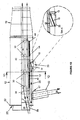
- FIG. 1A , 1B and 1C show a module 10 for use with an engine according to an example of the present invention.
- the engine itself which may be a bypass turbofan jet engine, such as bypass turbofan jet engines available from Nissan (http://world.honda.com/AircraftEngines/), is not shown in these figures.
- turbofan jet engines conventionally include an inlet fan which forces cold air into the engine. Downstream of the inlet fan, turbofan jet engines are segmented into a central core engine and an annular bypass flow region surrounding the core engine.
- the core engine is encased in an inner casing.
- An outer casing is provided outside of the inner casing. The inner and the outer casing define an annular outer bypass channel through which a part of the cold air can flow to the tail end of the engine. Another part of the cold air conveyed into the engine by the inlet fan flows into the core engine and is used in the core engine's combustion process.
- the core engine includes a compressor at the upstream end of the engine which compresses air introduced into the engine by the inlet fan, a combustion section in which fuel is combusted causing the heating and expansion of the compressed air, and a turbine that is rotated by the heated, compressed air. The rotation of the turbine is used to drive the inlet fan and compressor.
- the module 10 is arranged to be coupled to a downstream end of a bypass turbofan engine and comprises a cap 20 for controlling the flow of both the hot gas exhausted from the rear of the core engine as well as of the cold bypass air into the module 10.
- the cap 20 is arranged so that it can be coupled to the inner casing of the engine in a manner that maintains the separation between the high temperature exhaust gas that has passed through the core engine, and the lower temperature, high velocity air that bypassed the core engine.
- a shroud may further be provided outside of the outer casing part 28 to streamline the module 10.
- An outer casing part 22 of the cap 20 is arranged so that it can be connected to the outer casing of the engine without restricting flow of cold air from the engine.
- An inner casing part 24 of the cap 20 is dimensioned so that it can be connected to the inner casing of the engine without restricting flow of air from the bypass flow region of the engine or from the core engine.
- a central part 26 is further provided. This central part 26 defines the effective flow area available for the conveying of hot gas from the core engine.
- the cross-section of the flow area defined by the outer casing part 22 and by the inner casing part 24 and the cross-section of the flow area defined by the inner casing part 24 and the central part 26 are chosen so that their ratio is substantially the same as the ratio of the corresponding cross-sectional flow areas of the engine.
- a central tube or hot core 12 Downstream of the inner casing part 24 is a central tube or hot core 12 to which the inner casing part 24 is connected.
- the central tube/hot core 12 substantially separates the hot gas from the cold air flow as will be described in more detail below.
- the outer casing part 22 extends into a casing part 28 that surrounds the central tube/hot core 12 and defines a cold air bypass channel 14.
- a nozzle 19 is provided to guide and accelerate both the hot and the cold gas flow from the downstream end of the module 10. No separator separating the hot and the cold gas flows is provided in the nozzle 19.
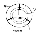
- the central tube/hot core 12 is mounted inside the casing part 28 by radially and longitudinally spaced brackets 30, as indicated in Figures 1B and 1C and as shown in detail in the cross-sectional view of Figure 1D .
- the brackets 30 comprise a holding surface in contact with the outside of the central tube/hot core 12.
- a part of the bracket 30 extends from the outside of the central tube/hot core 12 through the wall of the central tube/hot core 12 and contacts and holds an inside surface of the central tube/hot core 12.
- the central tube/hot core 12 is contained within and supported by a housing 45, indicated by the dashed line in Figure 1E , which may be a mesh or a perforated sheet.
- the housing 45 may be made of stainless steel.
- the openings in the housing 45 may have an increasing size along the length of the housing 45 towards the downstream end of the engine.
- FIG. 1B and 1C there is an opening 17 provided in the casing part 28 of the module 10, providing fluid communication between the cold air bypass channel 14 and the outside of the module 10.
- the opening 17 includes a closure, such as for example an iris type closure 21 as shown in Figure 1C , which allows the opening 17 to be selectively opened and closed. Where the closure is such an iris type closure, it can be opened and closed by a rotary actuator (not shown).
- the opening 17 is a fluid communication with a duct 32.
- the duct 32 illustrated in Figures 1A and 1B is angled in a backward direction by 10 degrees from the vertical direction.
- a nozzle 23 (shown in dashed lines in Figure 1E ) may further be provided to change the direction of the re-directed bypass air flow.
- the bypass air flow may, for example, have a direction between 0 degrees and 45 degrees relative to the vertical direction when it exits the duct 32 or the nozzle 23 associated with the duct 32.
- a baffle 18 is provided downstream of the opening 17.
- the baffle 18 is situated in a recessed section 33 shown in Figures 1A to C of the casing part 28 so that they do not present any resistance to the flow of the cold bypass air in the cold air bypass channel 14 when the baffle 18 is down.
- a ram 16 is provided to lift the baffle 18 into the cold air bypass channel so that they cause an obstruction to the flow of cold bypass air in the bypass air channel 14.
- the baffle 18 is formed by five overlapping petals 34, as is best shown in Figures 1F and 1G .
- the ram 16 is arranged to contact the central one of these five petals 34 and to exert an upwardly directed pressure on this central petal 34. This lifts the central petal as well as the remaining petals away from the casing part 28 due to the interleaving of the petals 34.
- the petals 34 can be extended until their free ends substantially contact the outer surface of hot core/central tube 12.
- the baffle 18/petals 34 extend only around a part of the circumference of the cold air bypass flow channel 14.
- the baffles 18 extend around a quarter of the circumference of the cold air bypass channel 14. Fully extending the petals 34 until they contact the central tube/hot core 12 can thus not lead to a complete obstruction of the cold air bypass air channel 14.
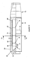
- FIG. 2 illustrates the pressure distribution in the module 10 when the baffle 18 is raised so as to be in contact with the central tube/hot core 12 and when the closure 17 is open. It can be seen from this figure that the pressure immediately upstream of the baffle 18 is greatly increased. This increase in pressure causes the bypass air to be exhausted through the opening 17. It can further be seen that the pressure build up does not propagate back into the engine, which could cause a surge. Instead, the pressure immediately upstream of the opening 17 is lower than the pressure diametrically opposite of the opening 17.
- a jet of hot exhaust gas from the turbine/core engine passes along the inside of the central tube/hot core 12, and is exhausted through the downstream end of the central tube/hot core 12.
- the opening 17 is closed and the baffles 18 are aligned with the inside of the casing part 28, then cold bypass air from the engine flows unimpededly through the cold air bypass annulus 14.
- the entirety of the air flow through the module 10 is exhausted at the downstream end of the module 10 through the nozzle 19 together with the hot gas flowing through the central part of the module 10 defined the central tube/hot core 12.
- the entirety of the cold air flow through the bypass air channel 14 is used for creating horizontal thrust.
- FIGS 1B and 2 show the module 10 in a second, different operating mode in which the opening 17 is at least partially or fully opened.
- a part of the cold bypass air passing through the channel 14 is diverted to pass through the opening 17 as airflow 36 as is indicated by the arrows in Figure 1B .
- This airflow 36 will be at high velocity, since the airflow 36 is branched from the high velocity bypass air driven into the engine by the fan.
- Initial computer models evaluating the conditions inside of the module 10 have shown that gas speeds of more than 350 m s -1 occur. Owing to the speed of the branched airflow 36, the branched airflow 36 is able to generate thrust.
- the airflow 36 is able to generate a component of thrust in a different direction to the main thrust produced by the engine.
- the flow of air through the bypass air channel 14, and therefore the flow of air through the outlet 17 can be controlled.
- a part of the cold air flow is used to generate lift, while the remainder of the cold air flow is used for creating horizontal thrust, as can also be seen from Figure 1B .
- the entirety of the flow of hot gas is of course used for the generation of horizontal thrust.
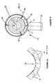
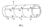
- FIG. 3 One arrangement of a central tube/hot core 12 is shown in detail in Figure 3 .
- the central tube/hot core 12 if formed of four annular sections 38, 40, 42 and 44 that are arranged in series along the longitudinal axis of the module 10.
- Each of the annular sections 40, 42 and 44 is formed of three segments 46.
- Each segment 46 extends over a third of the total circumference of the central tube/hot core 12 with gaps 48 being provided adjacent segments 46. These gaps allow for thermal expansion of the segments 46 under the influence of heat.
- the gaps 48 provided upstream of the central tube/hot core 12 are wider than gaps provided further downstream.
- the upstream section 38 is fixedly secured in place.
- a spring loaded end cap (not shown) is provided downstream of section 44 to restrict downstream longitudinal movement of the sections 38, 40, 42 and 44. The spring loading of this end cap allows for thermal expansion of the sections 38, 40, 42 and 44 in the longitudinal direction.
- the segments 46 are held in place by the brackets 30 discussed above with reference to Figure 1D .
- the use of these brackets 30 and the presence of gaps 48 allows easy removal and replacement of a segment 46 in case of damage to the segment.
- the hot gas flowing inside the central tube/hot core 12 can reach temperatures of 800 Kelvin and flow velocities of more than 350 m s -1 .
- Ferrite fibre that have been found to provide good performance under these conditions are fibres made of stainless steel SS 304 and/or SS 434 having a mean fibre length of between 300 and 600 ⁇ m and a fibre length to diameter ratio of between 6 and 12 and sintered together at a pressure of 0.001 mbar at a temperature of 1100-1250 degrees Centigrade. A sintering time of about 2-3 hours is usually found to be sufficient. Fibers having a mean length of between 300 and 400 ⁇ m and a length to diameter ratio of 6 to 7, for example, allow producing a relative density of 25 to 30%.
- the relative density can be decreased by increasing the mean fiber length and/or by increasing the length to diameter ratio of the fibers.
- An increase in relative density can be achieved by using shorter fibers and/or fibers that have a lower length to density ratio.
- To further increase the relative density it is further possible to compress the porous fiber network after sintering.
- the materials mentioned are, however, only exemplary materials and the use of other materials suitable for withstanding the environmental conditions found in the module 10 is of course also envisaged.
- the porosities of the annular sections 38, 40, 42 and 44 of the embodiment shown in Figure 3 differ in that the porosity of annular sections located downstream is higher than the porosity of annular sections located further upstream.
- One way of defining the porosity of the annular sections 38, 40, 42 and 44 is to express their porosity in terms of relative density.
- the relative density of an object can be calculated by dividing the mass of a volume of the object by the mass of a solid block of the material making up the object, wherein the solid block has the same volume as the volume of the object.
- One cubic centimetre of SS 304 for example, may weigh 8 grams.
- the relative density of a section made of SS 304 can be determined by dividing the mass of one cubic centimetre of the section by this value.
- the mass of one cubic centimetre of the section 38 is 7.2 grams and this section can therefore be said to have a relative density of 90%.
- the masses of one cubic centimetre of the sections 40, 42 and 44 are 4.8 gram, 3.2 gram and 2.4 gram respectively. These sections can therefore be said to have relative densities of 60%, 40% and 30% respectively.
- the relative density of a section can, for example, be adjusted by an appropriate choice of the fibre dimensions.
- a relative density of 25-30% can, for example, be achieved by sintering fibres having a mean fibre length of between 300 to 400 ⁇ m and a ratio of fibre length to fibre diameter of about 6 or 7.
- Lower relative densities can be achieved by choosing longer fibres and/or higher ratios between fibre length and fibre diameter.
- Higher relative densities can be achieved by choosing shorter fibres and/or lower ratios between fibre length and fibre diameter.
- the relative density of the sintered fibre material can, for example, be further increased by compressing the sintered fibre material so as to induce plastic deformation.
- section 38 that is the section with the lowest porosity extents across and further downstream than the opening 17. Only a limited amount of hot air can thus flow from the inside of the central tube/hot core 12 into the cold air flow annulus 14 at the upstream end of the central tube/hot core 12. The temperature of the air that can be exhausted from the duct 32 is thus not significantly increased due to intermixing of the cold bypass air with the hot air from the core engine. This protects objects that come into contact with the air flow exhausted from the duct 32 from heat damage.
- section 38 is not formed of fibrous material but is instead formed of a solid material that completely prevents the flow of hot gas into the bypass flow annulus.
- the porous nature of the central tube/hot core 12 gives rise to a number of advantages. Parts of the hot and cold gas flows inside and outside of the central tube/hot core 12 can, for example, cross the wall of the central tube/hot core 12 with increasing ease as they progress further downstream due to the increasing porosity of the central tube/hot core 12. This allows for intermixing of the gases and thus for a reduction in the disparity in the temperatures of the hot and cold gases. This effect is of course further aided by the good temperature conductivity of the material making up the central tube/hot core 12.
- the temperature conditions found in the module 10, that is a module comprising a porous central tube/hot core 12, and the temperature conditions found in a module of equivalent dimension but using a smooth non-porous hot core were determined using computer simulation. Both modules were evaluated in the operating state in which the closure 17 is closed and the baffle 18 is lowered. The highest temperature is found in modules in the central part of the hot air flow that is spaced apart from the hot core. The length and diameter of this hottest part of the hot air flow that extends downstream/outside of the nozzle 19 was found to be considerably reduced when the porous hot core is used.
- the maximum temperature of the air exhausted from the nozzle 19 of the module 10 using a porous central tube/hot core 12 is reduced by 30 to 40 Kelvin when compared to the maximum temperature exhausted by a module using a non-porous hot core. This corresponds to a reduction in temperature of up to 5%.
- the temperature of the bypass air flow is of course increased due to heat being conducted through the wall of the central tube/hot core 12 and due to interchange of hot and cold gas flows across the wall of the central tube/hot core 12.
- a porous central tube/hot core 12 in the module 10 provides an advantageous amount of attenuation of the noise generated by the engine that would in the absence of the porous central tube/hot core 12 be transmitted from the inside of the central tube/hot core 12 to its outside.
- noise representative of engine noise that would be encountered in the module 10 was introduced into the upstream end of the central tube/hot core 12. It was found that the central tube/hot core 12 attenuates the noise intensity of this noise by up to 10 dB. This 10 dB reduction in noise of course corresponds to a 50% reduction in the amount of noise transmitted to the outside of the central tube/hot core 12. It will be appreciated that this reduction is significant.
- a further advantage arising from the use of a porous central tube/hot core 12 is that, when the baffle 18 is raised the cold air can pass around the baffle 18 in a rapid fashion and at least partially flow into the central tube/hot core 12. This is not possible when a non-porous central tube is used and in this case the cold bypass air is deflected by the baffle 18 and flows around the central tube/hot core 12.
- a deflected air flow flowing around the central tube/hot core 12 in one direction meets a further deflected air flow flowing around the central tube/hot core 12 in the other direction at a position downstream and diametrically opposite of the baffle 18.
- Computer simulations have shown that this may lead to air flowing at supersonic speed diametrically opposite of the baffle 18. This may give rise to stability problems which are avoided by the porous central tube/hot core 12 of the preferred embodiment.
- the flow velocities found in the module 10, that is a module comprising a porous central tube/hot core 12, the temperature conditions of a module of equivalent dimension but using a smooth non-porous hot core were determined using computer simulation. Both modules were again evaluated in the operating state in which the closure 17 is closed and the baffle 18 is lowered.
- the maximum gas flow speed in the annulus 14 of the module comprising the non-porous central tube/hot core 12 is 336 m s -1 and occurs diametrically opposite and somewhat downstream of the baffle 18.
- the maximum gas flow speed in the module comprising the porous hot core occurs at approximately the same location but is only 310 m s -1 , that is about 8 % lower than the maximum air flow speed encountered in a module using a non-porous hot core.
- the module 10 described with relation to Figures 1A to 1C has an overall length of 2.8 m.
- the outer casing part 28 has an outer diameter of 52 cm.
- the central tube/hot core 12 has an outer diameter of 39 cm, and is 32 mm thick.
- the spacing between the outer surface of the central tube/hot core 12 and the inner surface of the outer casing part 28 is about 1.2 cm.
- the hot core extends rearwardly over 1.7 m measured from the front face of cap 20.
- Each of the annular sections 40, 42 and 44 is about 37 cm long.
- the annular section 38 has a length of about 14 cm.
- Each segment 46 extends over 120 degrees of the total circumference of the central tube/hot core 12.
- the opening 17 is located about 30 cm downstream of the front face of the cap 20 and the baffles 18 are centred about 105 cm downstream of the front face of cap 20.
- Petals 34 having a length of about 170 mm have been found to provide a satisfactory pressure build up in the cold air flow annulus 14.
- the baffle 18 extends around a quarter of the circumference of the cold air bypass channel 14.
- the duct 32 has a diameter of about 19 cm and is angled in a backward direction by 10 degrees from the vertical direction.
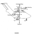
- the engine and module 10 are arranged on an aircraft 50, as shown in Figure 4 , in a preferred example two engines are provided on the aircraft 50, one engine being provided on or under each wing of the aircraft, and being arranged symmetrically with respect to the centre axis of the aircraft 50.
- two engines are provided on the aircraft 50, one engine being provided on or under each wing of the aircraft, and being arranged symmetrically with respect to the centre axis of the aircraft 50.
- the outlet 17 of each of the modules is connected to a duct that passes through the wing on which the engine is mounted.
- the outlet 17 exhausts to a duct which ends with one or more nozzles, such as nozzle 23, on the underside of the wing through which the airflow is directed.
- the outlet 17 may be provided with one or more nozzles that are directed generally downwardly.
- the baffles 18 are raised and the iris is opened to open the outlet 17. In this way, the hot gas exhausted from the engine, and a proportion of the cold bypass air is jetted from the rear of the engine to provide forward thrust, while a portion of the cold bypass air is directed through the outlet 17 and the ducting 32 in the underside of the wings or engines to provide an element of vertical thrust. This element of vertical thrust will assist the take off of the aircraft, allowing the aircraft to take off at a lower velocity and therefore requiring a shorter runway.
- the baffles 18 can be lowered and the outlet 17 closed by closing the iris. In this way, all of the available thrust from the hot and cold air is jetted from the rear of the module, and therefore provides forward thrust.
- the total lift achieved by an aircraft depends on a number of factors. One of these factors is of course the horizontal speed of the aircraft. A further factor is the design of the airfoils of the aircraft.
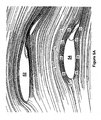
- the aircraft 50 illustrated in Figure 4 comprises two main wings 52 to each of which one engine/module 10 is fitted and a pair of second wings or airfoils 54. These airfoils 54 are arranged below the main wings 52 and slightly set back from the centres of the main wings 52, as can be seen from Figures 5A , 5B , 6A and 6B .
- the engines and the modules 10 are mounted on top of the main wings 52 and the duct (not shown) of the modules 10 extends through the main wings 52, so that a part of the bypass air flow can be exhausted to the areas below the main wings 52.
- Figures 5A and 5B illustrate the aircraft 50 in an operational mode in which no bypass air flow is exhausted in the downward direction.
- the numbers surrounding the airfoil 54 in Figure 5A are flow velocities in m s -1 and may be achieved during take off at 50 knots.
- the numbers surrounding the airfoil 54 in Figure 5B are pressure values in Pascal measured relative to the surrounding atmospheric pressure.
- the illustrated airfoil 54 has a lift coefficient of 0.48.
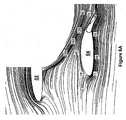
- Figures 6A and 6B illustrate the aircraft 50 in an operational mode in which bypass air flow is exhausted in the downward direction through the duct 32 of the module 10 and through the wing 52.
- the numbers surrounding the airfoil 54 in Figure 6A are again air flow velocities in m s -1 .
- the flow velocity of the air exhausted from the module 10 is considerably higher than the velocity of air flow that is due to the horizontal movement of the aircraft.
- the jet of air exhausted from the module 10 is directed towards the downstream part of the airfoil 54.
- Figure 6B shows the pressure distribution about the airfoil 54.
- the numbers surrounding the airfoil 54 in this figure are again pressure values in Pascal measured relative to the surrounding atmospheric pressure.
- the difference in the air pressures above and below the airfoil 54 is markedly increased when compared to the pressure distribution of Figure 5B .
- This increase in pressure difference manifests itself in an increase of lift obtained from the airfoil 54 and the lift coefficient achieved with the airfoil is 1.940 in the configuration shown in Figures 6A and 6B .
- the jet of air from the module 10 By directing the jet of air from the module 10 so that it impinges on a part of the lower airfoil 54, preferably on a downstream part of this airfoil 54 and even more preferably towards the downstream edge of or the downstream flap associated with the airfoil 54, an increase in lift coefficient of more than 300% was thus achieved.
- the jet of air provided by the module 10 thus not only provides an element of vertical thrust when being exhausted from duct 32 under the wing 52 but further serves to enhance the lift obtained from the airfoil 54.
- the wings 52 shown in Figures 5A , 5B , 6A and 6B has a horizontal depth/chord length of 3.8 m and a thickness to chord ratio of 15%.
- the wing 52 has an incidence of 2 degrees and the flap associated with the wing 52 is a 35 degree single slotted fowler flap.
- the airfoil 54 has a depth/chord length of 3 m and a thickness to chord ratio of 21%.
- the airfoil 54 has an incidence of 2 degrees and the flap associated with the airfoil 54 is a 20 degree plain flap.
- the upper surface of the wing 52 is vertically spaced from the upper surface of the airfoil 54 by 2 m and the leading edge of the airfoil 54 is set back by 1.4 m from the leading edge of the wing 52.
- the angle at which the air is exhausted out of the duct 32 is 25 degrees.
- a small part 58 of the air flow exhausted through the duct 32 from the module 10 is taken from the air flow so that it is not exhausted downwardly towards the airfoil 54. Instead, this part of the air flow is exhausted through an opening 56 in the upper surface of wing 52 in a manner that increases the air speed above the wing 52. This increase in air speed increases the amount of lift obtained from the wing 52.
- the part of the air flow may be taken from the duct 32 by providing a T-junction 60 in duct 32 that allows the bleeding off of a small amount of the air flow.
- the nominal jetted air flow 56 can compensate for small irregularities in the airflow along the downstream part of the lower surface of the wing 52 caused by suction through the gap between the trailing edge of the wing 52 and the leading edge of the flap attached to the wing 52.
- the aircraft 50 can, for example be operated during take off by accelerating the aircraft to a horizontal speed in which the horizontal flow of air caused by the rolling of the aircraft provides an amount of lift.
- this first phase of take off all of the cold bypass air flow is used to generate horizontal thrust.
- the baffle 18 of the module 10 is raised and the opening 17 is opened so that part of the cold bypass air flow is exhausted through the duct 32, thereby creating further vertical lift and causing the aircraft to lose contact with the ground, rather than having to create this further lift by accelerating further on the runway and thus requiring a significantly longer runway.
- the baffle 18 is raised while the opening 17 is being opened.
- the landing gear is retracted, causing a reduction in drag and thus a further acceleration of the aircraft.
- the baffle 18 is lowered and the opening 17 closed so that all of the cold air bypass flow is again used for creating horizontal thrust.
- the baffle 18 is raised in a rapid fashion and the opening 17 is also opened quickly.
- the baffle 18 is raised on the opening 17 is opened in less than three seconds. Doing so will provide an immediate impulse of vertical thrust before the reduction in horizontal thrust caused by the re-directing of the part of the cold bypass air into duct 32 reduces the degree of horizontal acceleration of the aircraft. This impulse, if applied at the correct moment, will cause the aircraft to become airborne.
- the total thrust provided by the engines can be automatically or manually increased to compensate for the decrease in horizontal thrust caused by the redirecting of bypass air.
- the total horizontal acceleration of the aircraft thus remains unaltered. It may be that, if the overall thrust provided by the engines is not increased when the vertical thrust pulse is created, the aircraft could decelerate due to drag and ground friction forces acting on the aircraft.
- the vertical thrust pulse created by the re-directing of bypass air creates an instant acceleration component in the vertical direction as, at the time at which this thrust component is generated, the weight of the aircraft is almost completely balanced or compensated for by the lift created by the horizontal movement of the aircraft.
- Measure to reduce drag of the aircraft as described above can then be implemented to compensate for any reduction in horizontal acceleration that may be caused by the re-directing of the portion 36 of the cold bypass air flow. Once a positive rate of incline is achieved by the aircraft the re-directed bypass airflow 36 used for generating vertical thrust can be allowed to again be exhausted from the downstream end of the module 10.
- the efficiency and operation of an aircraft using an engine according to the present invention has been determined computationally, and indicates that the use of less than 15% of the available bypass thrust from an engine would enable an aircraft to take off from a runway of less than 125m.
- the exact length of runway required for an aircraft using the module 10 to become airborne depends on a variety of factors, such as, for example, the ambient temperature, the local wind velocity, the pressure altitude and the density altitude at which the runway is located. From such factors the speed at which the aircraft can become airborne with the assistance of the vertical air jet can be determined while the aircraft is stationary on the runway. The pilot can thus be provided with an estimate of the length of runway required for takeoff and of the correct point in time at which to initiate the vertical air jet. This point in time coincides with the latest decision point at which take-off can be aborted safely in order to stop the aircraft within the prescribed emergency stopping distance. As the decision point to take-off or abort is located considerably closer to the end of the runway at which the take-off procedure is commenced the total length of the runway is considerably reduced when compared to runways suitable for the take-off and landing of conventional aircraft.
- the downwardly directed bypass airflow 36 can also be used to reduce the distance in which an aircraft can come to a halt during landing or reduce the braking force that needs to be applied during the landing procedure. Shortly before the aircraft touches the ground during landing the iris can again be opened to open the outlet 17 and the baffle 18 raised to cause a portion of the cold air to flow through the outlet 17. At the same time lift is created by the re-directed air flow 36. This allows the pilot to reduce the speed of the aircraft and it may be possible to fly the aircraft at a speed that is below the normal stalling speed the same aircraft has when the air flow 36 is not re-directed. The re-directing of the air flow 36 thus reduces the stalling speed of the aircraft. After the aircraft has made contact with the ground a routine braking procedure can be used to bring the aircraft to a halt. As the aircraft already has a reduced speed at the beginning of this routine braking procedure the aircraft can land in a shorter distance than would otherwise be the case.
- the aircraft 50 is arranged so that, in the case of the failure of one of the engines the remaining operable engine will automatically sense the reduction in power provided by the failing or failed engine and operation of the mechanism re-directing the bypass air flow is prevented.
- the module has been described separately from the engine itself, the module may be formed integrally with the engine.
- the factors affecting the take off capabilities of an aircraft include the lift, weight, thrust, drag and rolling friction forces that will act on the aircraft.
- the lift and drag forces are dependent on the design of the aircraft itself, and can be estimated using Prandtl-Lanchester's lifting line theory. Using this theory, an example of the parameters for an aircraft according to the present invention have been determined as set out below.
- the lift and drag forces result from aerodynamic and non-aerodynamic characteristics of an aircraft, summarised by the coefficients of lift and drag.
- the following examples have employed initial estimates for these important coefficients, based both on an elliptic distribution of circulation over the wing of the modelled aircraft and available data on parasite drag experienced by wings and bluff bodies. These estimates feature in these preliminary results because of a chief objective to determine the take-off capabilities of the modelled aircraft rapidly. It should be noted that increasing the installed thrust of the engines will of course allow for an increase in aircraft size and weight. Therefore, the following example merely sets out to describe existing formulae that can be used in this instance.
- C L 1.0 is used in the early estimation of take-off analysis for the aircraft.
- the maximum CL that is likely for the modelled aircraft using the empirical formula to estimate takeoff distance based on THOMAS C. CORKE, "Design of Aircraft", Prentice Hall, Pearson Education Inc., NJ, US, 2003 , is: S to 20.9 W S ⁇ 1 C l max ⁇ W T + 87 ⁇ W S ⁇ 1 C L max
- Oswald efficiency factor mainly depends on the wing characteristics. At low lift coefficients with elliptical lift distributions, ⁇ of the wing tends to unity. At high C L , M and the jet deflection ⁇ v , the drag polar does not have a parabolic behaviour since the flow separation strongly affects the lift distributions on the lifting surfaces.
- ⁇ ⁇ AR C L ⁇ ⁇ 1 - ⁇ + ⁇ - 1 where ⁇ is called the leading-edge suction factor.
- ⁇ ⁇ AR C L ⁇ ⁇ 1 - ⁇ + ⁇ - 1
- ⁇ is called the leading-edge suction factor.
- This parameter depends on the camber, the leading-edge radius, the sweep-back angle ⁇ and the Re of the aerodynamic surfaces.
- ⁇ is usually of order 0.9 to 0.95 and at take-off conditions, ⁇ is of order 0.7.
- Jet deflections change the lift distribution on the aerodynamic surfaces and the local M, and therefore will affect ⁇ and K.
- One of the first semi-empirical methods to investigate the reduction of wing induced-drag factor due to thrust-vectoring was presented by Maskell & Spence (1959) and then modified by Capone (1975).
- the relation between ⁇ v , local M and local C L must be known to make it possible to theoretically evaluate the thrust-vectoring effects on K. Therefore, these effects cannot be formulated easily and they will be estimated using the results of experiment, CFD or of the Vortex Lattice Method (VLM).
- Recent V/STOL aircraft are designed to have bigger Oswald's efficiency factor and smaller C D0 .
- the lift curve slope, C L ⁇ (Raymer 1999, modified version of equation from Lowry & Polhamus, 1957)
- C L ⁇ 2 ⁇ ⁇ AR 2 + 4 + AR ⁇ 1 - M 2 0.95 2 ⁇ 1 + tan 2 ⁇ max t 1 - M 2 S exposed S reference ⁇ 1.07 ⁇ 1 + d F b F 2
- ⁇ maxt is the wing swept at the maximum thickness location.
- d F is the average diameter of the fuselage.
- S exposed is the exposed wing planform which is the reference area of wing minus the part of the wing area covered by the fuselage.
- the equation C D can be calculated in another way.
- C Do ⁇ out - of - ground - effect 16 ⁇ h / b 2 1 + 16 ⁇ h / b 2
- h is the average height of the wing above the ground and b is the wingspan.
- k 1 in eq. (4) is proportionality constant for increment of parasite drag due to lift, C Di .
- k 3 is proportionality constant for increment of induced drag due to lift.
- C D C Do + k ⁇ C L G 2 + ⁇ ⁇ C Do flap + ⁇ ⁇ C Do LG
- C Do is related to the conventional flight drag polar at cruise conditions.
- ⁇ C Do(flap) is the increase in C Do due to flaps (named as 'added base drag due to flaps' by Corke) and the typical values are given below:
- Table 4 Flap Type (the flap span is 60% of wing span and the flap chord is 25% of wing mean aerodynamic chord) ⁇ f ⁇ C Do(flap) Fowler 30 0.032 Fowler 50 0.083 Split / Plain 30 0.05 Split / Plain 50 0.10 Slotted 30 0.02 Slotted 50 0.05
- C L ( G ) is the lift coefficient due to the ground effect.
- the ground effect increases the effective UD of the aircraft at take-off and also can decrease the lift-induced drag.
- C D C Do + ⁇ ⁇ C Do flap + ⁇ ⁇ C Do LG + Gk ⁇ C L 2
- C Do is the zero-lift coefficient at cruise conditions.
- ⁇ C Do(flap) is estimated using Table 4 and ⁇ C Do(LG) is from eq. (8) and G is from eq. (11).
- Subscript v refers to the V/STOL (vectored) aircraft compared to the unvectored reference aircraft.
- the first two terms on the right-hand side of eqs. (1) & (2) are purely related to the body and tail.
- the last term corrects the induced drag coefficient to account for the interference effects.
- K h in eq. (1) may be determined by treating the horizontal tail as a smaller wing (Raymer 1992), but experimental or computational studies need to be done to estimate K h,v in eq. (2).
- the induced-drag coefficient of a conventional tail is much smaller than the one for a swept wing.
- the change of the Oswald efficiency factors may be estimated using the leading-edge suction method and treating the horizontal tail as a small wing. This needs some curve fitting to obtain suitable relations for the leading-edge suction factor from the graphs presented in the DATCOM's or in Raymer's semi-empirical methods.
- T o a o - a 1 ⁇ h + a 2 ⁇ h 2 - a 3 ⁇ h 3 + b o - b 1 ⁇ h - b 2 ⁇ h 2 + b 3 ⁇ h 3 ⁇ ( c o - c 1 ⁇ M + c 2 ⁇ M 2 - c 3 ⁇ M
- a o to a 3 , b o to b 3 and c o to c 3 are positive constant coefficients and can be found using a curve-fitting technique.
- the total engine thrust is split into two parts, with a part contributing to the forward linear momentum of the aircraft and a portion providing an upward thrust to augment the aerodynamic lift.
- T f T o - k V ⁇ T o ;
- T u k V ⁇ T o ;
- L tot L + T u
- the nozzle opening expression used in this study remains smooth for all velocity magnitudes, which induces a smooth variation of total lift, as detailed in the Results section.
- the maximum k max of k is a parameter that corresponds to a percentage of the total thrust.
- the downward-jet should.begin not at the start of the ground roll, but at a more strategic time, in order to allow speed hence aerodynamic lift to increase rapidly so that the needed upward thrust absorbs only a percentage of the total engine thrust. In the example, for instance, 10 to 15 % of the total engine thrust directed upward is sufficient to allow the aircraft to lift off.
- the aerodynamic lift contributes the bulk of total lift, with the upward thrust contributing just that additional upward force sufficient for the aircraft to take off within 125m.
- the aircraft's speed during ground roll can reach larger magnitudes, which requires a smaller magnitude of upward thrust for lift-off within 125m.
- the aircraft's speed during ground roll can reach larger magnitudes, which requires a smaller magnitude of upward thrust for lift-off within 125m.
- the forward speed of the aircraft will be reduced.
- the forward speed at the 125 m mark becomes higher and reduces the percentage of thrust deflected downwards.
- the time to reach the 125 m mark are respectively 6.2 s, 6 s and 5.5 s for thrust settings 4750 lbf, 5000 lbf and 6000 lbf.
- central tube/hot core 12 has been described hereinbefore as having four longitudinally contiguously arranged annular sections, other central tubes/hot cores may comprise a different number of longitudinally contiguously arranged annular sections or may be formed of only a single annular section, while still falling within the scope of the present invention.
- annular segment 40, 42 and 44 of the above described embodiment are further shown as comprising three segments. In other embodiments in accordance with the present invention each or a segment may, however, comprise a different number of segments or be made of a single piece.
- the central tube/hot core 12 has further been described as having segments with differing porosities. It will be appreciated that this is not essential to the present invention and central tubes/hot cores that have a substantially constant but non-zero porosity along their length are also envisaged.
Abstract
Description
- The present invention relates to an improved engine for use with an aircraft, and to an aircraft including such an engine. The invention also relates to a module for use with an engine, particularly for use with a bypass turbofan type engine.
- Jet bypass turbofan engines are well known propulsion systems for aircraft.
- A jet bypass turbofan engine includes a turbofan engine having an inlet for air, a compressor for compressing the inlet air, a combustion section in which fuel is combusted to cause the expansion of the compressed air and a turbine which is rotated by the expanded, heated compressed air. The expanded, heated compressed air passes through the rear of the engine as a jet of heated gas. The rotation of the turbine is used to drive the compressor that compresses the incoming air. Further, the rotation of the turbine is used to drive an inlet fan which draws air into the engine. A portion of the inlet air is passed to the compressor for compression in the turbofan engine. Another portion of the air is channelled around the turbofan engine as 'bypass' air. This air flows through the bypass channel at a high speed. Mixers are provided in a downstream part of the engine for mixing the cold, high velocity, bypass air with the jet of heated gas exhausted from the turbofan engine. Together, the mixed high velocity bypass air and heated exhaust gas are jetted from the engine to provide thrust.
- The generally horizontal jet of exhaust gas from the engine provides forward thrust to propel an aircraft to which the engine is mounted. When the aircraft is on the ground and is accelerated to reach a certain velocity, the aircraft is able to take off. However, especially for large planes, it is necessary to provide a long runway to enable the thrust from the jet engine to accelerate the aircraft to the required velocity to enable the aircraft to take off. This means that aircraft are only able to take off, and therefore are only able to land, at locations where there is a sufficiently long runway. This means that aircraft are often not able to land close to the final destination of passengers.
- Vertical and short takeoff and landing (V/STOL) aircraft are known. It is known to mount a turbofan engine on an aircraft in such a way that the entire engine or the entire jet efflux can be rotated such that the jet of exhaust gas from the engine jets in a generally vertical direction rather than in a horizontal direction. This vertical jet produces an upward thrust, allowing the aircraft to take off without requiring a high velocity. An example of the use of such a system is found in the well known "Harrier" jump jet. However, whilst this vertical jet can allow the aircraft to take off vertically, this uses a significant amount of energy, and therefore is not an efficient way for an aircraft to take off.
- Another problem with existing bypass turbofan engines is that they generate a considerable amount of engine noise. One source of noise is the combustion process in the engine and vibrations associated with the combustion process. Jet noise is further generated when the hot gas exhausted from the tail end of the engine contacts cold ambient air and thereby induces a rapid expansion of this ambient air. It is desirable to reduce the amount of noise emitted by an engine to reduce the amount of disturbance caused by air traffic, in particular in heavily populated areas.
- According to one aspect of the present invention, a module for use with a bypass turbofan jet engine is provided. The module is generally elongate, and includes a generally axially extending central portion through the length of the module for exhausting the hot exhaust gas from the engine, and a generally axially extending peripheral portion surrounding the central portion for the bypass air from the engine. An outlet is provided from the peripheral portion of the module through the outer casing to enable at least a portion of the bypass air to be directed out of the module at an angle to the axis of the module.
- The remainder of the bypass air is thus exhausted in the horizontal direction and is available for creating horizontal thrust.
- The module may be provided as a separate module that can be added to the exhaust end of an engine, or may be formed together with the engine. The bypass air that is directed through the outlet provides an element of thrust. By providing the outlet at an angle to the axis of the module, namely at an angle to the direction of the exhaust gas from the rear of the engine, this re-directed air will generate thrust in a direction different from that of the normal exhaust gas from the engine. In the normal operation of the engine, in which the main exhaust gas is exhausted generally horizontally from the rear of the engine, the portion of the bypass air can be directed generally vertically to produce a vertical thrust force. This can be used in take off to increase the lift and therefore decrease the velocity at which the aircraft needs to travel for take off. This can in turn mean that the aircraft can take off from a shorter runway than would otherwise be possible, which in turn makes the aircraft usable in more locations, often closer to the intended destination. During landing the aircraft can be decelerated below the normal stalling speed of the aircraft, that is the horizontal speed required for creating sufficient lift to keep the aircraft airborne when the portion of the bypass air is not redirected, while still remaining airborne as additional lift is created by the downwardly directed bypass air flow. The aircraft can thus be flown at a reduced speed just before touching the ground. The braking forces required for stopping the aircraft in a desired distance can thus be reduced and/or the distance within which the aircraft can be brought to a halt can be reduced.
- It is preferred that the portion of the bypass air that passes through the outlet during takeoff is equal to or less than 25%, equal to or less than 20%, equal to or less than 15%, in the range of 1% to 15%, equal to or less than 10% or equal to or less than 5% of the total volume of bypass air leaving the engine.
- It is preferred that the outlet for the portion of bypass air is selectively controllable.
- In a preferred example of the invention, an adjustable baffle is provided within the peripheral portion/bypass airflow of the module, preferably downstream of the outlet. The baffle may comprise a number of overlying petals or sheets that can be moved into the peripheral portion so as to hinder an air flow in the peripheral portion. Adjustment of the baffle, which may be achieved by an electrically or pneumatically controlled ram, is able to control the air flow through the peripheral portion. This can help control the thrust generated by the air jets from the outlet and from the rear of the module.
- It is preferred that the outlet can be selectively opened and closed to allow or hinder the portion of bypass air from being exhausted at an angle to the main thrust or to vary the amount of bypass air that is allowed to exhaust through the opening. When the outlet is closed, none of the bypass air will be exhausted at an angle to the main direction of thrust, and therefore all of the available thrust is used to drive the aircraft forwards. It is further preferred that the distance over which the baffle extends into the bypass air flow paths is additionally selectively controlled. Control of the opening state of the opening and of the deployment state of the baffle permits varying the amount of bypass air that is allowed to exhaust through the opening. This allows control of the bypass air to give a varied degree of thrust at an angle to the main thrust from the exhaust. Raising of the baffle increases the pressure in the part of the peripheral portion upstream of the baffle. The increased pressure forces a portion of the bypass air flow out of the opening. The increase in pressure caused by the baffle does not extend upstream of the opening.
- It is also preferred that the relative orientation of the air through the outlet can be selectively controlled. This allows control of the direction of the additional thrust. This can be achieved by the provision of nozzles, the orientation of which can be controlled. For example, during take off, the nozzle can be orientated so that the portion of the air is jetted generally vertically downwards to increase the lift. It is preferred that angle to the axis of the module referred to above is between 45 degrees and 90 degrees. The direction of the part of the cold air flow exhausted to below the module has thus an angle between 0 degrees and 45 degrees relative to the vertical direction and directed backwardly.
- It will be appreciated that more than one outlet may be provided from the module. In this case, the outlets may be controllable independently or in common.
- It is preferred that the module includes a separator between the central and peripheral portions to separate the bypass air and the hot exhaust gas. An advantage of keeping the relatively cold bypass air and the relatively hot exhaust gas from the turbine separate, and using a portion of the cold bypass air alone to produce the directional thrust, means the overall noise level of the engine can be kept down. This means that the module is able to produce a directional thrust component at a much lower noise level than would be the case merely by redirecting the entire engine or the entire jet efflux so that all of the thrust has a vertical component.
- Furthermore, where the directional thrust is directly vertically, by merely directing the cold air downwards rather than the hot exhaust gas from the engine, there is less risk of burning or otherwise damaging the ground or any aircraft components below the engine.
- In a preferred example, the separator is in the form of an open network of porous ferrite fibre mesh. The open network of porous ferrite fibre mesh allows a small portion of the hot exhaust gas to permeate into the open fibre network as the cold bypass air cools the network.
- This has been recognised as being advantageous in its own right and according to another aspect of the present invention there is provided a module for use with a bypass turbofan jet engine. The module comprises a generally elongate housing, and includes a central portion extending through the length of the module for exhausting the hot exhaust gas from the engine and a peripheral portion surrounding the central portion for the bypass air from the engine. The module further includes a separator for separating the central and peripheral portions. The separator comprises an open network of porous mesh that allows a degree of fluid flow through a wall of the separator.
- The use of a mesh separator between the central and peripheral portions will enable a reduction in the noise, thought to be achieved by a reduction in the kinetic energy, from the engine.
- The separator has been recognised as being advantageous in its own right and according to another aspect of the present invention there is provided a separator comprising an open network of porous mesh for use in separating the bypass air flow of a bypass turbofan jet engine from the hot gas flow of the engine.
- This form of separator may replace the mixers normally used in turbine engines. As the preferred separator can be manufactured to be more lightweight than such mixers the total weight of an engine can be reduced. Alternatively the separator can be used as a stage upstream of a mixer.
- The ferrite fibre material forming the mesh preferably consists of stainless steel ferrite fibres. The mesh is preferably formed by sintering. The ferrite fibres preferably have a mean length of between 300 and 600 µm, more preferably between 300 and 500 µm and most preferably between 300 and 400 µm. The length to diameter ratio of the fibres is preferably between 6 and 12, more preferably between 6 and 9 and most preferably between 6 and 7. Fibres having a length of less than 300 µm and a length to diameter ratio of less than 6 may be used to generate porous fibre mesh with a higher density.
- It is preferred that a means for restricting fluid flow through the wall of the separator is provided. This means is preferably adapted to allow more fluid to pass through a downstream part of the separator than through a part of the separator further upstream than the downstream part. The means may take the form of a sleeve that includes holes to permit an amount of air to pass through the separator.
- The sleeve can be provided around the separator, inside the separator or embedded in the separator. In the upstream portion of the module, the sleeve can have small holes to allow a small amount of hot gas to permeate through the separator. By permitting only a small amount of hot gas to pass through the separator it is ensured that, in modules having an outlet as described above, the portion of bypass air that may be directed out of the peripheral portion is not excessively heated by the hot gas. Downstream, the openings in the sleeve can be of increased size. The sleeve may be a sheet material comprising holes or a mesh material.
- Alternatively or in addition to the above discussed sleeve another way of adjusting the amount of gas that can pass through the separator is to provide the separator with a porosity appropriate to restrict fluid flow to a desired degree. The porosity of the porous fibre mesh at a downstream part of the separator may be chosen to be preferably higher than the porosity of the porous fibre mesh in a part upstream of the downstream part. The porosity of the porous fibre mesh can increase along the length of the separator in a downstream direction. This increase may be a gradual increase or a stepped increase.
- The separator is preferably formed of a plurality of portions arranged adjacent each other along a length of the separator. The properties of one of the portions differs from the properties of another one of the portions. The porosity of a portion arranged in a downstream part of the separator is preferably higher than the porosity of a portion arranged upstream of the portion arranged in the downstream part of the separator. More preferably the porosity of each of the portions is higher than the porosity of an adjacent portion arranged further upstream. Providing the separator in the form of a plurality of portions allows that, when part of the separator gets worn or damaged only a short length of the separator needs to be removed and replaced. This can save material costs and also reduces the amount of work involved in accessing and replacing the separator part when compared to the replacing of the entire separator.
- The separator, or one or more of the portions is preferably an annulus that is formed of a plurality of segments wherein each such segment extends around only a fraction of the circumference of the annulus. A separator segmented into such segments and portions allows easy removal of a segment or portion, for example when such a segment is damaged and needs to be replaced.
- Segmenting the separator has been recognised as being advantageous in its own right and according to an another aspect of the present invention there is provided an annular separator for separating the bypass air flow of a bypass turbofan jet engine from the hot gas flow of the engine. The circumference of the separator is segmented into a number of segments over at least part of the length of the separator.
- Segments or sections arranged in an upstream part of the separator will likely experience a higher temperature than segments or sections arranged further downstream. Gaps between the segments and sections can be arranged to be larger in an upstream section than in a downstream section to account for the differences in heat expansion of these sections.
- Means for supporting the network of porous mesh are further preferably provided. This means may take the form of brackets and/or a sleeve arranged inside or outside of the fibre mesh or embedded in the fibre mesh. This sleeve can be the same sleeve used for imposing a gas flow restriction on the porous mesh.
- According to another aspect of the invention, there is provided an aircraft including a bypass turbofan jet engine and associated module according to the first and/or second aspects of the invention.
- In this case, it is preferred that the aircraft includes at least two bypass turbofan jet engines and modules. Where the aircraft includes two or more engines, it is preferred that these are arranged symmetrically on the aircraft. For example, where two engines are provided, it is preferred that one engine is provided on each side of the aircraft. Where the module includes an opening for directing a portion of the bypass air at an angle to the main exhaust jet, it is preferred that the outlets are controlled so that the portion of the bypass air flowing at an angle from each of the engines is the same. This is important since otherwise there is a risk that the directional thrust component may twist or turn the aircraft. In particular, it is preferred that the sensors are provided to sense the extent to which the outlets are open and/or the direction of the airflow through the outlets and/or the velocity of air passing through the outlets to ensure that these are the same. In the event that a single engine failure should occur, or the total thrust or vertical thrust is reduced outside of a 5% differential limit between the engines, then the vertical thrust component will either be removed from the live engine or reduced accordingly.
- An engine can be mounted either above or below the wings. In the case of overwing engines in which, the module is arranged to direct a portion of the bypass air at an angle to the main exhaust jet, ducting may be provided through the wing of the aircraft to direct the portion of the bypass air through the wing to provide the thrust. In this case, nozzles can be provided at the end of the ducting to control the direction of the thrust. With the engines mounted either under wing or over wing, the vertically directed by-pass airflow can be vented to atmosphere via one or more nozzle.
- A part of the re-directed bypass air may be bled of the flow or re-directed bypass air, for example through a T-junction in the through wing ducting, and blown over the upper surface of the wing of the aircraft. The fluid flow created in this manner can, for example, compensate for small irregularities in the airflow along a downstream part of the lower surface of the wing, such as irregularities that may be caused by suction through the gap between the trailing edge of the wing and the leading edge of a flap attached to the wing.
- It has been recognised that the directed air flow is not only useful in creating vertical thrust but can also be directed over an upper surface of an airfoil of the aircraft to create further lift. This has been recognised as being advantageous in its own right and according to another aspect of the present invention there is provided an aircraft comprising a pair of bypass turbofan engines wherein each engine is associated with a module according to the first aspect of the present invention and with an airfoil. The engines and modules are arranged so that at least part of the portion of the diverted bypass air directed out of the modules flows over at least part of an upper surface of the associated airfoil at least when the aircraft travels at a predetermined speed. The predetermined speed is preferably the normal stalling speed of the aircraft or a speed suitable for take off and/or landing of the aircraft. The portion of the bypass air may thus be directed over the airfoil at times when lift generated by the portion of the bypass air is most useful, namely during take off or landing and/or when the aircraft would under normal circumstances and without the use of the directed air flow not be able to become or remain airborne, namely when the aircraft moves at a speed that is lower than the normal stalling speed of the aircraft. The term normal stalling speed hereby refers to the minimum speed the aircraft would be required to have to generate sufficient lift to become or remain airborne without additional air being blown over an airfoil. It will be appreciated that this aspect of the present invention is of course not only useful when the aircraft moves at a speed close to its normal stalling speed but that the advantage of increased lift can be obtained over a wide range of aircraft speeds both above and below the stalling speed. By redirecting the airflow over the wing the speed of the aircraft can be reduced at higher safe altitudes and the aircraft can loiter for prolonged periods.
- The directed air flow may also be used to entrain part of the generally horizontal air flow the aircraft experiences due to the aircraft's horizontal movement. The re-directed portion of the bypass airflow thus accelerates a part of the horizontal flow with which the direct flow comes into contact. This acceleration can further improve lift, for example when the accelerated air flow is an air flow that flows over an upper surface of an airfoil.
- The module is preferably arranged to, in use, direct the re-directed portion of the bypass airflow towards a downstream part of the upper surface of the airfoil, more preferably towards a downstream flap provided on the airfoil.
- The airfoil towards which the re-directed portion of the bypass air is directed may be a main wing of the aircraft. In addition to this airfoil or wing the aircraft can comprise a further pair of airfoils or wings. In this case each of the engine is mounted to one airfoil or wing of the further pair of airfoils or wings. Preferably the engine is mounted above or below the further airfoil or wing.
- It is preferred that the directed air flow is only activated once the aircraft has gathered the above discussed predetermined speed. The aircraft may comprise means arranged to cause the portion of bypass air to be directed out of the module at the angle to the axis of the module when the predetermined speed of the aircraft is reached.
- The present invention of course also extends to a module comprising the features of a module according to the first aspect of the present invention and also the features of a module according to the second aspect of the present invention.
- According to another aspect of the present invention there is provided a method of operating an aircraft comprising a module according to the above discussed first aspect of the invention during take-off. The method comprises accelerating the aircraft to a predetermined speed and starting to re-direct the portion of the bypass air once the predetermined speed has been reached.
- Preferably the aircraft is accelerated to the first speed while still on the ground and the re-directing of the portion of the bypass air is also started while the aircraft is still on the ground. The downwardly directed fluid flow is then actuated to provide additional lift assisting during take off without the need for further horizontal acceleration.
- It is preferred that the opening of the module is opened substantially simultaneously with the raising of the baffle of the module. To avoid an undue deceleration of the aircraft due to the reduction of horizontal thrust caused by the redirecting of bypass air flow it is preferred that the opening of the opening is completed in less than three seconds and that the baffle is raised within the same time. The method may further include the step of increasing the overall thrust output of the aircraft's engine to compensate for the loss in horizontal thrust caused by the redirecting of bypass air.
- The directed air flow may be interrupted after the aircraft has become airborne so that all of the bypass air flow can again be used for generating horizontal thrust. The re-directed bypass airflow is preferably interrupted after the landing gear has been retracted. It is not as important to perform the interrupting of the directed air flow in the same speedy manner as the establishing of the air flow and it is acceptable for the opening to be closed and the baffle to be lowered over a time frame of twenty seconds or more.
- It is further desirable that the direction at which the bypass air is exhausted is adjusted so that the bypass air is directed so as to maximise lift. The direction of the directed air flow can be adjusted to achieve the correct balance between vertical thrust and entrainment under in use conditions, i.e. when the exhausted cold bypass air interacts with the horizontal air flow caused by the horizontal movement of the aircraft. This adjustment could be an adjustment that does not change during the course of a flight and may be performed by a technician prior to a flight.
- The present invention also extends to a method of operating an aircraft comprising a module according to the above first aspect of the present invention during landing. The method comprises approaching a runway at a landing speed and starting to re-direct the portion of the bypass air while the aircraft is airborne. The re-directed portion of the bypass air provides a lift component that assists in keeping the aircraft airborne. This may allow the speed of the aircraft to be reduced below the normal stalling speed the aircraft would have in the absence of the re-directed air flow while the aircraft is still airborne. In the method of the present invention the speed of the aircraft when contacting the ground can thus be chosen to be lower than the minimum speed required for the same aircraft in the absence of the re-directed air flow. This reduction in speed can reduce the length of runway and/or the amount of braking force required for bringing the aircraft to a halt.
- The present invention also extends to a method of operating an aircraft comprising a pair of modules according to the above first aspect of the present invention, each module associated with an engine, wherein the flow or re-directed bypass air is adjusted to produce an amount of vertical thrust that is substantially equal to the amount of vertical thrust created by the other engine. The amount of vertical thrust generated by one engine may thus for example be adjusted to be within 5% of the amount of vertical thrust generated by the other engine.
- While the above described methods can be performed in a manual fashion by a pilot it has been recognised that it is desirable to be able to perform these methods in an automatic fashion.
- According to another aspect of the present invention there is provided a computer program product adapted to perform one or more of the above methods when executed. This computer program product may have means for actuating the baffle in the module, means for opening and/or closing the opening in the module but may also be connected to sensors that detect the speed of the aircraft so that the aircraft can automatically determine when the desired first speed is reached.
- Preferably further sensors are adapted to determine an outside ambient temperate, the local wind velocity, the pressure altitude and/or the density altitude at which the runway is located. From the data obtained by the sensors the computer program product can determine the speed applicable to the particular flight conditions at which the part of the bypass air should be re-directed. It is of course not essential that such a determination is made for every flight and a situation in which the determination is made once for a given aircraft, for example after the completion of the aircraft's manufacture and possibly based on data obtained with sensors not incorporated in the aircraft, is also envisage.
- The present invention will now be described by way of example with reference to the accompanying drawings, in which:
-
Figure 1A shows a perspective view of a module according to the present invention; -
Figure 1B shows a sectional side view of the module ofFigure 1A ; -
Figure 1C shows a sectional bottom view of the module ofFigure 1A and1B ; -
Figure 1D shows a cross-sectional view of the module alongline 1D-1D shown inFigures 1B and1C ; -
Figure 1E shows a sectional side view of a further module comprising a sleeve around the hot core; -
Figure 1F shows a front view of the module ofFigures 1A to 1C ; -
Figure 1G shows details of the baffle; -
Figure 2 shows the results of a simulation of the pressure distribution in a module comprising a porous hot core; -
Figure 3 shows a perspective view of a hot core/central tube in accordance with a preferred embodiment of the present invention; -
Figure 4 shows a diagram of a preferred aircraft incorporating the engine of the present invention; -
Figure 5A shows a velocity distribution about the wings of the aircraft shown inFigure 4 in an operational mode in which no bypass air flow is exhausted in the downward direction; -
Figure 5B shows a pressure distribution about the wings of the aircraft shown inFigure 4 in an operational mode in which no bypass air flow is exhausted in the downward direction; -
Figure 6A shows a velocity distribution about the wings of the aircraft shown inFigure 4 in a further operational mode in which bypass air flow is exhausted in the downward direction; -
Figure 6B shows a pressure distribution about the wings of the aircraft shown inFigure 4 in a further operational mode in which bypass air flow is exhausted in the downward direction; -
Figure 7 shows an arrangement in which part of the cold air flow is directed over the upper wing of the aircraft shown inFigure 4 ; and -
Figure 8 shows a free body diagram of the aircraft shown inFigure 4 . -
Figure 1A ,1B and1C show amodule 10 for use with an engine according to an example of the present invention. The engine itself, which may be a bypass turbofan jet engine, such as bypass turbofan jet engines available from Honda (http://world.honda.com/AircraftEngines/), is not shown in these figures. - Bypass turbofan jet engines conventionally include an inlet fan which forces cold air into the engine. Downstream of the inlet fan, turbofan jet engines are segmented into a central core engine and an annular bypass flow region surrounding the core engine. The core engine is encased in an inner casing. An outer casing is provided outside of the inner casing. The inner and the outer casing define an annular outer bypass channel through which a part of the cold air can flow to the tail end of the engine. Another part of the cold air conveyed into the engine by the inlet fan flows into the core engine and is used in the core engine's combustion process.
- The core engine includes a compressor at the upstream end of the engine which compresses air introduced into the engine by the inlet fan, a combustion section in which fuel is combusted causing the heating and expansion of the compressed air, and a turbine that is rotated by the heated, compressed air. The rotation of the turbine is used to drive the inlet fan and compressor.
- The
module 10 is arranged to be coupled to a downstream end of a bypass turbofan engine and comprises acap 20 for controlling the flow of both the hot gas exhausted from the rear of the core engine as well as of the cold bypass air into themodule 10. Thecap 20 is arranged so that it can be coupled to the inner casing of the engine in a manner that maintains the separation between the high temperature exhaust gas that has passed through the core engine, and the lower temperature, high velocity air that bypassed the core engine. A shroud may further be provided outside of theouter casing part 28 to streamline themodule 10. - An
outer casing part 22 of thecap 20 is arranged so that it can be connected to the outer casing of the engine without restricting flow of cold air from the engine. Aninner casing part 24 of thecap 20 is dimensioned so that it can be connected to the inner casing of the engine without restricting flow of air from the bypass flow region of the engine or from the core engine. Acentral part 26 is further provided. Thiscentral part 26 defines the effective flow area available for the conveying of hot gas from the core engine. The cross-section of the flow area defined by theouter casing part 22 and by theinner casing part 24 and the cross-section of the flow area defined by theinner casing part 24 and thecentral part 26 are chosen so that their ratio is substantially the same as the ratio of the corresponding cross-sectional flow areas of the engine. - Downstream of the
inner casing part 24 is a central tube orhot core 12 to which theinner casing part 24 is connected. The central tube/hot core 12 substantially separates the hot gas from the cold air flow as will be described in more detail below. Theouter casing part 22 extends into acasing part 28 that surrounds the central tube/hot core 12 and defines a coldair bypass channel 14. Anozzle 19 is provided to guide and accelerate both the hot and the cold gas flow from the downstream end of themodule 10. No separator separating the hot and the cold gas flows is provided in thenozzle 19. - The central tube/
hot core 12 is mounted inside thecasing part 28 by radially and longitudinally spacedbrackets 30, as indicated inFigures 1B and1C and as shown in detail in the cross-sectional view ofFigure 1D . Thebrackets 30 comprise a holding surface in contact with the outside of the central tube/hot core 12. In addition, a part of thebracket 30 extends from the outside of the central tube/hot core 12 through the wall of the central tube/hot core 12 and contacts and holds an inside surface of the central tube/hot core 12. - In the arrangement shown in
Figure 1E the central tube/hot core 12 is contained within and supported by ahousing 45, indicated by the dashed line inFigure 1E , which may be a mesh or a perforated sheet. Thehousing 45 may be made of stainless steel. The openings in thehousing 45 may have an increasing size along the length of thehousing 45 towards the downstream end of the engine. - As shown in
Figures 1B and1C , there is anopening 17 provided in thecasing part 28 of themodule 10, providing fluid communication between the coldair bypass channel 14 and the outside of themodule 10. Theopening 17 includes a closure, such as for example aniris type closure 21 as shown inFigure 1C , which allows theopening 17 to be selectively opened and closed. Where the closure is such an iris type closure, it can be opened and closed by a rotary actuator (not shown). Theopening 17 is a fluid communication with aduct 32. Theduct 32 illustrated inFigures 1A and1B is angled in a backward direction by 10 degrees from the vertical direction. A nozzle 23 (shown in dashed lines inFigure 1E ) may further be provided to change the direction of the re-directed bypass air flow. The bypass air flow may, for example, have a direction between 0 degrees and 45 degrees relative to the vertical direction when it exits theduct 32 or thenozzle 23 associated with theduct 32. - A
baffle 18 is provided downstream of theopening 17. In one arrangement thebaffle 18 is situated in a recessedsection 33 shown inFigures 1A to C of thecasing part 28 so that they do not present any resistance to the flow of the cold bypass air in the coldair bypass channel 14 when thebaffle 18 is down. Aram 16 is provided to lift thebaffle 18 into the cold air bypass channel so that they cause an obstruction to the flow of cold bypass air in thebypass air channel 14. - In the illustrated preferred embodiment the
baffle 18 is formed by five overlappingpetals 34, as is best shown inFigures 1F and 1G . Theram 16 is arranged to contact the central one of these fivepetals 34 and to exert an upwardly directed pressure on thiscentral petal 34. This lifts the central petal as well as the remaining petals away from thecasing part 28 due to the interleaving of thepetals 34. As is shown inFigures 1B ,1E and1F , thepetals 34 can be extended until their free ends substantially contact the outer surface of hot core/central tube 12. - It can be seen from
Figure 1F that thebaffle 18/petals 34 extend only around a part of the circumference of the cold airbypass flow channel 14. In the illustrated embodiment thebaffles 18 extend around a quarter of the circumference of the coldair bypass channel 14. Fully extending thepetals 34 until they contact the central tube/hot core 12 can thus not lead to a complete obstruction of the cold airbypass air channel 14. - Simulations have shown that when the
opening 17 is opened while thebaffle 18 is lowered, the amount of air flowing into the vent is minimal. However, when thebaffle 18 is raised and theclosure 17 is opened simultaneously, the velocity of air flowing into theduct 32 is substantial. Tests have also confirmed that the increase in pressure created upstream of thebaffle 18 by the raising of thebaffle 18 extends up to theopen closure 17, whereupon it is dissipated into theduct 32. This prevents surge back into the bypass engine. -
Figure 2 illustrates the pressure distribution in themodule 10 when thebaffle 18 is raised so as to be in contact with the central tube/hot core 12 and when theclosure 17 is open. It can be seen from this figure that the pressure immediately upstream of thebaffle 18 is greatly increased. This increase in pressure causes the bypass air to be exhausted through theopening 17. It can further be seen that the pressure build up does not propagate back into the engine, which could cause a surge. Instead, the pressure immediately upstream of theopening 17 is lower than the pressure diametrically opposite of theopening 17. - Turning now to the operation of the
module 10, in use a jet of hot exhaust gas from the turbine/core engine passes along the inside of the central tube/hot core 12, and is exhausted through the downstream end of the central tube/hot core 12. When theopening 17 is closed and thebaffles 18 are aligned with the inside of thecasing part 28, then cold bypass air from the engine flows unimpededly through the coldair bypass annulus 14. In this configuration the entirety of the air flow through themodule 10 is exhausted at the downstream end of themodule 10 through thenozzle 19 together with the hot gas flowing through the central part of themodule 10 defined the central tube/hot core 12. In this configuration the entirety of the cold air flow through thebypass air channel 14 is used for creating horizontal thrust. -
Figures 1B and2 show themodule 10 in a second, different operating mode in which theopening 17 is at least partially or fully opened. In this configuration a part of the cold bypass air passing through thechannel 14 is diverted to pass through theopening 17 asairflow 36 as is indicated by the arrows inFigure 1B . Thisairflow 36 will be at high velocity, since theairflow 36 is branched from the high velocity bypass air driven into the engine by the fan. Initial computer models evaluating the conditions inside of themodule 10 have shown that gas speeds of more than 350 m s-1 occur. Owing to the speed of the branchedairflow 36, the branchedairflow 36 is able to generate thrust. As theairflow 36 is directed at an angle to the main exhaust gas flow, theairflow 36 is able to generate a component of thrust in a different direction to the main thrust produced by the engine. By controlling the height of thebaffle 18 and the opening of theoutlet 17, the flow of air through thebypass air channel 14, and therefore the flow of air through theoutlet 17 can be controlled. In this operating mode a part of the cold air flow is used to generate lift, while the remainder of the cold air flow is used for creating horizontal thrust, as can also be seen fromFigure 1B . The entirety of the flow of hot gas is of course used for the generation of horizontal thrust. - In the following the architecture of a preferred central tube/
hot core 12 will be described in more detail. One arrangement of a central tube/hot core 12 is shown in detail inFigure 3 . As can be seen fromFigure 3 , the central tube/hot core 12 if formed of fourannular sections module 10. Each of theannular sections segments 46. Eachsegment 46 extends over a third of the total circumference of the central tube/hot core 12 withgaps 48 being providedadjacent segments 46. These gaps allow for thermal expansion of thesegments 46 under the influence of heat. Thegaps 48 provided upstream of the central tube/hot core 12 are wider than gaps provided further downstream. This is advantageous as an increased amount of expansion of thesegments 46 occurs upstream of the central tube/hot core 12 than downstream due to the higher temperatures upstream. Theupstream section 38 is fixedly secured in place. A spring loaded end cap (not shown) is provided downstream ofsection 44 to restrict downstream longitudinal movement of thesections sections - The
segments 46 are held in place by thebrackets 30 discussed above with reference toFigure 1D . The use of thesebrackets 30 and the presence ofgaps 48 allows easy removal and replacement of asegment 46 in case of damage to the segment. - In a
typical module 10, the hot gas flowing inside the central tube/hot core 12 can reach temperatures of 800 Kelvin and flow velocities of more than 350 m s-1. Ferrite fibre that have been found to provide good performance under these conditions are fibres made of stainless steel SS 304 and/or SS 434 having a mean fibre length of between 300 and 600 µm and a fibre length to diameter ratio of between 6 and 12 and sintered together at a pressure of 0.001 mbar at a temperature of 1100-1250 degrees Centigrade. A sintering time of about 2-3 hours is usually found to be sufficient. Fibers having a mean length of between 300 and 400 µm and a length to diameter ratio of 6 to 7, for example, allow producing a relative density of 25 to 30%. The relative density can be decreased by increasing the mean fiber length and/or by increasing the length to diameter ratio of the fibers. An increase in relative density can be achieved by using shorter fibers and/or fibers that have a lower length to density ratio. To further increase the relative density it is further possible to compress the porous fiber network after sintering. The materials mentioned are, however, only exemplary materials and the use of other materials suitable for withstanding the environmental conditions found in themodule 10 is of course also envisaged. - The porosities of the
annular sections Figure 3 differ in that the porosity of annular sections located downstream is higher than the porosity of annular sections located further upstream. One way of defining the porosity of theannular sections - In the preferred embodiment shown in
Figure 3 , the mass of one cubic centimetre of thesection 38 is 7.2 grams and this section can therefore be said to have a relative density of 90%. The masses of one cubic centimetre of thesections - The relative density of a section can, for example, be adjusted by an appropriate choice of the fibre dimensions. A relative density of 25-30% can, for example, be achieved by sintering fibres having a mean fibre length of between 300 to 400 µm and a ratio of fibre length to fibre diameter of about 6 or 7. Lower relative densities can be achieved by choosing longer fibres and/or higher ratios between fibre length and fibre diameter. Higher relative densities can be achieved by choosing shorter fibres and/or lower ratios between fibre length and fibre diameter. The relative density of the sintered fibre material can, for example, be further increased by compressing the sintered fibre material so as to induce plastic deformation.
- It can be seen from
Figures 1B and1C that thesection 38, that is the section with the lowest porosity extents across and further downstream than theopening 17. Only a limited amount of hot air can thus flow from the inside of the central tube/hot core 12 into the coldair flow annulus 14 at the upstream end of the central tube/hot core 12. The temperature of the air that can be exhausted from theduct 32 is thus not significantly increased due to intermixing of the cold bypass air with the hot air from the core engine. This protects objects that come into contact with the air flow exhausted from theduct 32 from heat damage. In analternative arrangement section 38 is not formed of fibrous material but is instead formed of a solid material that completely prevents the flow of hot gas into the bypass flow annulus. - The porous nature of the central tube/
hot core 12 gives rise to a number of advantages. Parts of the hot and cold gas flows inside and outside of the central tube/hot core 12 can, for example, cross the wall of the central tube/hot core 12 with increasing ease as they progress further downstream due to the increasing porosity of the central tube/hot core 12. This allows for intermixing of the gases and thus for a reduction in the disparity in the temperatures of the hot and cold gases. This effect is of course further aided by the good temperature conductivity of the material making up the central tube/hot core 12. - The temperature conditions found in the
module 10, that is a module comprising a porous central tube/hot core 12, and the temperature conditions found in a module of equivalent dimension but using a smooth non-porous hot core were determined using computer simulation. Both modules were evaluated in the operating state in which theclosure 17 is closed and thebaffle 18 is lowered. The highest temperature is found in modules in the central part of the hot air flow that is spaced apart from the hot core. The length and diameter of this hottest part of the hot air flow that extends downstream/outside of thenozzle 19 was found to be considerably reduced when the porous hot core is used. The maximum temperature of the air exhausted from thenozzle 19 of themodule 10 using a porous central tube/hot core 12 is reduced by 30 to 40 Kelvin when compared to the maximum temperature exhausted by a module using a non-porous hot core. This corresponds to a reduction in temperature of up to 5%. At the same time the temperature of the bypass air flow is of course increased due to heat being conducted through the wall of the central tube/hot core 12 and due to interchange of hot and cold gas flows across the wall of the central tube/hot core 12. - As discussed in the background section, sudden contact of the hot air exhausted from the
module 10 with cold air causes a rapid expansion of the cold air and thus an increase in the noise level generated by the combination of the engine and themodule 10. As discussed above, the temperature of the hot gas exhausted by amodule 10 using a porous central tube/hot core 12, for example the central tube/hot core 12 shown inFigure 3 , is reduced. Because of this reduction in maximum temperature the discrepancy in temperature between the hot gas flow and the cold air flow is reduced. The expansion of the cold air flow when coming into contact with the hot air flow is thus less rapid. The expansion of the cold ambient air when coming into contact with the exhausted gas is also less rapid and the overall amount of noise generated by themodule 10 using the porous central tube/hot core 12 is thus reduced. A further reduction in the maximum temperature of the exhaust gas that comes into contact with the ambient air can be achieved by providing a mixer, such as a mixer commonly used in aircraft engines, downstream of the central tube/hot core 12 to mix the hot and cold gas flows. - It has further been found that the use of a porous central tube/
hot core 12 in themodule 10 provides an advantageous amount of attenuation of the noise generated by the engine that would in the absence of the porous central tube/hot core 12 be transmitted from the inside of the central tube/hot core 12 to its outside. In an experiments noise representative of engine noise that would be encountered in themodule 10 was introduced into the upstream end of the central tube/hot core 12. It was found that the central tube/hot core 12 attenuates the noise intensity of this noise by up to 10 dB. This 10 dB reduction in noise of course corresponds to a 50% reduction in the amount of noise transmitted to the outside of the central tube/hot core 12. It will be appreciated that this reduction is significant. - A further advantage arising from the use of a porous central tube/
hot core 12 is that, when thebaffle 18 is raised the cold air can pass around thebaffle 18 in a rapid fashion and at least partially flow into the central tube/hot core 12. This is not possible when a non-porous central tube is used and in this case the cold bypass air is deflected by thebaffle 18 and flows around the central tube/hot core 12. A deflected air flow flowing around the central tube/hot core 12 in one direction meets a further deflected air flow flowing around the central tube/hot core 12 in the other direction at a position downstream and diametrically opposite of thebaffle 18. Computer simulations have shown that this may lead to air flowing at supersonic speed diametrically opposite of thebaffle 18. This may give rise to stability problems which are avoided by the porous central tube/hot core 12 of the preferred embodiment. - The flow velocities found in the
module 10, that is a module comprising a porous central tube/hot core 12, the temperature conditions of a module of equivalent dimension but using a smooth non-porous hot core were determined using computer simulation. Both modules were again evaluated in the operating state in which theclosure 17 is closed and thebaffle 18 is lowered. The maximum gas flow speed in theannulus 14 of the module comprising the non-porous central tube/hot core 12 is 336 m s-1 and occurs diametrically opposite and somewhat downstream of thebaffle 18. The maximum gas flow speed in the module comprising the porous hot core occurs at approximately the same location but is only 310 m s-1, that is about 8 % lower than the maximum air flow speed encountered in a module using a non-porous hot core. - The
module 10 described with relation toFigures 1A to 1C has an overall length of 2.8 m. Theouter casing part 28 has an outer diameter of 52 cm. The central tube/hot core 12 has an outer diameter of 39 cm, and is 32 mm thick. The spacing between the outer surface of the central tube/hot core 12 and the inner surface of theouter casing part 28 is about 1.2 cm. The hot core extends rearwardly over 1.7 m measured from the front face ofcap 20. Each of theannular sections annular section 38 has a length of about 14 cm. Eachsegment 46 extends over 120 degrees of the total circumference of the central tube/hot core 12. - In the
module 10 theopening 17 is located about 30 cm downstream of the front face of thecap 20 and thebaffles 18 are centred about 105 cm downstream of the front face ofcap 20.Petals 34 having a length of about 170 mm have been found to provide a satisfactory pressure build up in the coldair flow annulus 14. Thebaffle 18 extends around a quarter of the circumference of the coldair bypass channel 14. Theduct 32 has a diameter of about 19 cm and is angled in a backward direction by 10 degrees from the vertical direction. - Turning now to the way the engine and
module 10 are arranged on anaircraft 50, as shown inFigure 4 , in a preferred example two engines are provided on theaircraft 50, one engine being provided on or under each wing of the aircraft, and being arranged symmetrically with respect to the centre axis of theaircraft 50. By mounting the engines symmetrically in this way tipping or twisting of the aircraft during use is avoided. - In the case of over wing mounted engines, the
outlet 17 of each of the modules is connected to a duct that passes through the wing on which the engine is mounted. In this way, when theoutlet 17 is opened and a portion of the bypass air is directed through theopening 17, the jet ofre-directed bypass air 36 is able to pass through the wings and generally vertically downwards. In this case, it is preferred that theoutlet 17 exhausts to a duct which ends with one or more nozzles, such asnozzle 23, on the underside of the wing through which the airflow is directed. When the engine is mounted under the wing, theoutlet 17 may be provided with one or more nozzles that are directed generally downwardly. - In use, when the aircraft is to take off, the
baffles 18 are raised and the iris is opened to open theoutlet 17. In this way, the hot gas exhausted from the engine, and a proportion of the cold bypass air is jetted from the rear of the engine to provide forward thrust, while a portion of the cold bypass air is directed through theoutlet 17 and theducting 32 in the underside of the wings or engines to provide an element of vertical thrust. This element of vertical thrust will assist the take off of the aircraft, allowing the aircraft to take off at a lower velocity and therefore requiring a shorter runway. When the aircraft is airborne, thebaffles 18 can be lowered and theoutlet 17 closed by closing the iris. In this way, all of the available thrust from the hot and cold air is jetted from the rear of the module, and therefore provides forward thrust. - The total lift achieved by an aircraft depends on a number of factors. One of these factors is of course the horizontal speed of the aircraft. A further factor is the design of the airfoils of the aircraft. The
aircraft 50 illustrated inFigure 4 comprises twomain wings 52 to each of which one engine/module 10 is fitted and a pair of second wings orairfoils 54. Theseairfoils 54 are arranged below themain wings 52 and slightly set back from the centres of themain wings 52, as can be seen fromFigures 5A ,5B ,6A and6B . The engines and themodules 10 are mounted on top of themain wings 52 and the duct (not shown) of themodules 10 extends through themain wings 52, so that a part of the bypass air flow can be exhausted to the areas below themain wings 52. -
Figures 5A and5B illustrate theaircraft 50 in an operational mode in which no bypass air flow is exhausted in the downward direction. The numbers surrounding theairfoil 54 inFigure 5A are flow velocities in m s-1 and may be achieved during take off at 50 knots. The numbers surrounding theairfoil 54 inFigure 5B are pressure values in Pascal measured relative to the surrounding atmospheric pressure. The illustratedairfoil 54 has a lift coefficient of 0.48. -
Figures 6A and6B illustrate theaircraft 50 in an operational mode in which bypass air flow is exhausted in the downward direction through theduct 32 of themodule 10 and through thewing 52. The numbers surrounding theairfoil 54 inFigure 6A are again air flow velocities in m s-1. As can be seen, the flow velocity of the air exhausted from themodule 10 is considerably higher than the velocity of air flow that is due to the horizontal movement of the aircraft. The jet of air exhausted from themodule 10 is directed towards the downstream part of theairfoil 54. It can further be seen from a comparison ofFigure 5A and6A that the air speed at the centre of the upper surface of theairfoil 54 increases from 30 m s-1 to 40 m s-1 when the jet of air from themodule 10 is provided. This is due to entrainment or the drawing in/acceleration of the horizontal air flow over theairfoil 54 by the jet of air exhausted from themodule 10. -
Figure 6B shows the pressure distribution about theairfoil 54. The numbers surrounding theairfoil 54 in this figure are again pressure values in Pascal measured relative to the surrounding atmospheric pressure. As can clearly be seen the difference in the air pressures above and below theairfoil 54 is markedly increased when compared to the pressure distribution ofFigure 5B . This increase in pressure difference manifests itself in an increase of lift obtained from theairfoil 54 and the lift coefficient achieved with the airfoil is 1.940 in the configuration shown inFigures 6A and6B . By directing the jet of air from themodule 10 so that it impinges on a part of thelower airfoil 54, preferably on a downstream part of thisairfoil 54 and even more preferably towards the downstream edge of or the downstream flap associated with theairfoil 54, an increase in lift coefficient of more than 300% was thus achieved. The jet of air provided by themodule 10 thus not only provides an element of vertical thrust when being exhausted fromduct 32 under thewing 52 but further serves to enhance the lift obtained from theairfoil 54. - The
wings 52 shown inFigures 5A ,5B ,6A and6B has a horizontal depth/chord length of 3.8 m and a thickness to chord ratio of 15%. Thewing 52 has an incidence of 2 degrees and the flap associated with thewing 52 is a 35 degree single slotted fowler flap. Theairfoil 54 has a depth/chord length of 3 m and a thickness to chord ratio of 21%. Theairfoil 54 has an incidence of 2 degrees and the flap associated with theairfoil 54 is a 20 degree plain flap. The upper surface of thewing 52 is vertically spaced from the upper surface of theairfoil 54 by 2 m and the leading edge of theairfoil 54 is set back by 1.4 m from the leading edge of thewing 52. The angle at which the air is exhausted out of theduct 32 is 25 degrees. - In the embodiment shown in
Figure 7 a small part 58 of the air flow exhausted through theduct 32 from themodule 10 is taken from the air flow so that it is not exhausted downwardly towards theairfoil 54. Instead, this part of the air flow is exhausted through anopening 56 in the upper surface ofwing 52 in a manner that increases the air speed above thewing 52. This increase in air speed increases the amount of lift obtained from thewing 52. The part of the air flow may be taken from theduct 32 by providing a T-junction 60 induct 32 that allows the bleeding off of a small amount of the air flow. The nominal jettedair flow 56 can compensate for small irregularities in the airflow along the downstream part of the lower surface of thewing 52 caused by suction through the gap between the trailing edge of thewing 52 and the leading edge of the flap attached to thewing 52. - Turning now to the operation of the
aircraft 50, theaircraft 50 can, for example be operated during take off by accelerating the aircraft to a horizontal speed in which the horizontal flow of air caused by the rolling of the aircraft provides an amount of lift. In this first phase of take off all of the cold bypass air flow is used to generate horizontal thrust. Once a predetermined speed is achieved thebaffle 18 of themodule 10 is raised and theopening 17 is opened so that part of the cold bypass air flow is exhausted through theduct 32, thereby creating further vertical lift and causing the aircraft to lose contact with the ground, rather than having to create this further lift by accelerating further on the runway and thus requiring a significantly longer runway. Preferably thebaffle 18 is raised while theopening 17 is being opened. Once the aircraft is airborne the landing gear is retracted, causing a reduction in drag and thus a further acceleration of the aircraft. Once the aircraft has gained sufficient height thebaffle 18 is lowered and theopening 17 closed so that all of the cold air bypass flow is again used for creating horizontal thrust. - It is preferred that, once the predetermined speed or the predetermined lift is achieved, the
baffle 18 is raised in a rapid fashion and theopening 17 is also opened quickly. In the preferred embodiment thebaffle 18 is raised on theopening 17 is opened in less than three seconds. Doing so will provide an immediate impulse of vertical thrust before the reduction in horizontal thrust caused by the re-directing of the part of the cold bypass air intoduct 32 reduces the degree of horizontal acceleration of the aircraft. This impulse, if applied at the correct moment, will cause the aircraft to become airborne. - The total thrust provided by the engines can be automatically or manually increased to compensate for the decrease in horizontal thrust caused by the redirecting of bypass air. The total horizontal acceleration of the aircraft thus remains unaltered. It may be that, if the overall thrust provided by the engines is not increased when the vertical thrust pulse is created, the aircraft could decelerate due to drag and ground friction forces acting on the aircraft. The vertical thrust pulse created by the re-directing of bypass air creates an instant acceleration component in the vertical direction as, at the time at which this thrust component is generated, the weight of the aircraft is almost completely balanced or compensated for by the lift created by the horizontal movement of the aircraft.
- Measure to reduce drag of the aircraft as described above can then be implemented to compensate for any reduction in horizontal acceleration that may be caused by the re-directing of the
portion 36 of the cold bypass air flow. Once a positive rate of incline is achieved by the aircraft there-directed bypass airflow 36 used for generating vertical thrust can be allowed to again be exhausted from the downstream end of themodule 10. - The efficiency and operation of an aircraft using an engine according to the present invention has been determined computationally, and indicates that the use of less than 15% of the available bypass thrust from an engine would enable an aircraft to take off from a runway of less than 125m.
- The exact length of runway required for an aircraft using the
module 10 to become airborne of course depends on a variety of factors, such as, for example, the ambient temperature, the local wind velocity, the pressure altitude and the density altitude at which the runway is located. From such factors the speed at which the aircraft can become airborne with the assistance of the vertical air jet can be determined while the aircraft is stationary on the runway. The pilot can thus be provided with an estimate of the length of runway required for takeoff and of the correct point in time at which to initiate the vertical air jet. This point in time coincides with the latest decision point at which take-off can be aborted safely in order to stop the aircraft within the prescribed emergency stopping distance. As the decision point to take-off or abort is located considerably closer to the end of the runway at which the take-off procedure is commenced the total length of the runway is considerably reduced when compared to runways suitable for the take-off and landing of conventional aircraft. - The downwardly directed
bypass airflow 36 can also be used to reduce the distance in which an aircraft can come to a halt during landing or reduce the braking force that needs to be applied during the landing procedure. Shortly before the aircraft touches the ground during landing the iris can again be opened to open theoutlet 17 and thebaffle 18 raised to cause a portion of the cold air to flow through theoutlet 17. At the same time lift is created by there-directed air flow 36. This allows the pilot to reduce the speed of the aircraft and it may be possible to fly the aircraft at a speed that is below the normal stalling speed the same aircraft has when theair flow 36 is not re-directed. The re-directing of theair flow 36 thus reduces the stalling speed of the aircraft. After the aircraft has made contact with the ground a routine braking procedure can be used to bring the aircraft to a halt. As the aircraft already has a reduced speed at the beginning of this routine braking procedure the aircraft can land in a shorter distance than would otherwise be the case. - The
aircraft 50 is arranged so that, in the case of the failure of one of the engines the remaining operable engine will automatically sense the reduction in power provided by the failing or failed engine and operation of the mechanism re-directing the bypass air flow is prevented. - It will be appreciated that whilst the module has been described separately from the engine itself, the module may be formed integrally with the engine.
- The factors affecting the take off capabilities of an aircraft include the lift, weight, thrust, drag and rolling friction forces that will act on the aircraft. The lift and drag forces are dependent on the design of the aircraft itself, and can be estimated using Prandtl-Lanchester's lifting line theory. Using this theory, an example of the parameters for an aircraft according to the present invention have been determined as set out below.
- The lift and drag forces result from aerodynamic and non-aerodynamic characteristics of an aircraft, summarised by the coefficients of lift and drag. The following examples have employed initial estimates for these important coefficients, based both on an elliptic distribution of circulation over the wing of the modelled aircraft and available data on parasite drag experienced by wings and bluff bodies. These estimates feature in these preliminary results because of a chief objective to determine the take-off capabilities of the modelled aircraft rapidly. It should be noted that increasing the installed thrust of the engines will of course allow for an increase in aircraft size and weight. Therefore, the following example merely sets out to describe existing formulae that can be used in this instance. While generating these accurate magnitudes, this initial study has employed the parameters listed below:
Table 1: Density ρ 0.002377 slugs/ft3 Acceleration of Gravity g 32.2 ft/s2 Total Weight W 6,500 lbf Coefficient of rolling friction µ 0.02 Wing Surface Area S 255.39 ft2 Wing Span b 37.05 ft Oswald's Wing efficiency e 0.7 Coefficient of Lift CL 1.0 Coefficient of Parasite Drag CDo 0.030 - For the coefficient of rolling friction, 0.02 has been chosen for the worst condition, namely icy concrete/asphalt. The calculation for a normal condition assuming the coefficient of rolling friction, 0.05 as a typical value (instead of 0.02).
- The table below gives ground rolling friction (resistance) coefficients obtained from DANIEL P. RAYMER, " Aircraft Design: A Conceptual Approach", Third Edition, American Institute of Aeronautics and Astronautics Inc., Rexton, VA, 1999.
Table 2: Type of Runway Surface Typical Values of µ Rolling (brakes off, take-off conditions) Brakes on (landing conditions) Dry concrete/asphalt 0.03-0.05 0.3-0.5 Wet concrete/asphalt 0.05 0.15-0.3 Icy concrete/asphalt 0.02 0.06-0.10 Hard turf 0.05 0.4 Firm turf 0.04 0.3 Soft turf 0.07 0.2 Wet grass 0.08 0.2 - However, EGBERT TORENBEEK, in "Synthesis of Subsonic Airplane Design", Kluwer Academic Publisher, Dordrecht, The Netherlands, 1982, gives the following typical value of µ:
Table 3: Surface Typical Values of µ Hard runways (concrete, tarmac) 0.02 Hard turf/ gravel 0.04 Short/ dry grass 0.05 Long grass 0.10 Soft ground 0.10 to 0.30 - As it can be seen, these values are slightly different from Raymer's values. It is better to use the values given in Table 2 in the take-off calculation. They provide results that are more realistic.
- CL =1.0 is used in the early estimation of take-off analysis for the aircraft. The maximum CL that is likely for the modelled aircraft using the empirical formula to estimate takeoff distance based on THOMAS C. CORKE, "Design of Aircraft", Prentice Hall, Pearson Education Inc., NJ, US, 2003, is:

- If the aircraft is to take off within a distance of 125 m, the above equation and thrust of 6000 lbf gives CLmax ≥ 5.4289.
- Experience shows that typically CLTO = 0.175 CLmaxTO is a good estimation for V/STOL aircraft and therefore CLTO = 0.95 will be acceptable for CLmax = 5.4289 or alternatively, the value of CLmax = 5.714 is suggested for the assumed value of CLTO = 0.1.
- It is not necessary to assume the value of Oswald's Wing efficiency and it can be calculated using the 'Leading-Edge Suction Method'. Otherwise the error will be very high on the induced-drag calculation in general and the induced-lift drag coefficient in particular.
- Oswald efficiency factor mainly depends on the wing characteristics. At low lift coefficients with elliptical lift distributions, ε of the wing tends to unity. At high CL, M and the jet deflection δv , the drag polar does not have a parabolic behaviour since the flow separation strongly affects the lift distributions on the lifting surfaces.
- Several semi-empirical equations to estimate K and the spanwise lift distribution have been developed over the years, such as those by Eppler (1997), Lam (1993), Raymer (1992), Rokhsaz (1993), Lowson (1990), Roskam (Part-6 1987), Covert (1985), Nicolai (1984), Butler (1983), Stinton (1983), Torenbeek (1982) and Laitone (1978).
- One of the methods which can predict ε better than other estimation methods, is called the 'leading-edge suction method' (e.g., Raymer 1992, Roskam Part-6 1987 and Covert 1985). It is briefly formulated as

where χ is called the leading-edge suction factor. For fully attached flow or full leading-edge suction χ = 1 and for fully separated flow or zero leading-edge suction χ = 0 . This parameter depends on the camber, the leading-edge radius, the sweep-back angle Λ and the Re of the aerodynamic surfaces. Although the three-dimensional calculation of χ is complicated and needs CFD techniques, it can be estimated from the DATCOM's (data compendium from the USAF) or Raymer's semi-empirical methods for the conceptual design. For a typical lifting surface of civil jet aircraft at cruise conditions, χ is usually of order 0.9 to 0.95 and at take-off conditions, χ is of order 0.7. - Jet deflections change the lift distribution on the aerodynamic surfaces and the local M, and therefore will affect ε and K. One of the first semi-empirical methods to investigate the reduction of wing induced-drag factor due to thrust-vectoring was presented by Maskell & Spence (1959) and then modified by Capone (1975). The relation between δv , local M and local CL must be known to make it possible to theoretically evaluate the thrust-vectoring effects on K. Therefore, these effects cannot be formulated easily and they will be estimated using the results of experiment, CFD or of the Vortex Lattice Method (VLM).
- After comparing different values of Oswald's efficiency factor from several methods of Cavallo (1966), Raymer (1989) and Roskam (1987) with the actual aircraft values, the following equation based upon the statistical data for is now suggested:

- Recent V/STOL aircraft are designed to have bigger Oswald's efficiency factor and smaller CD0. For a V/STOL subsonic aircraft, the lift curve slope, CLα (per radian) is (Raymer 1999, modified version of equation from Lowry & Polhamus, 1957)

- Λmaxt is the wing swept at the maximum thickness location. dF is the average diameter of the fuselage. Sexposed is the exposed wing planform which is the reference area of wing minus the part of the wing area covered by the fuselage.
- The wing aspect ratio and total coefficient of drag have been calculated using the formulae

- Denoting with V the forward speed, the lift and drag forces are then expressed as

- The equation CD can be calculated in another way.
- JOHN D. ANDERSON JR., in "Aircraft Performance and Design", McGraw Hill, Singapore, 1999, gives

where CDo is related to the conventional flight drag polar at cruise conditions and
- Factor Kuc depends on the amount of flap defection and its consequences on the landing gear drag. Typical values for Kuc are


- Parameter G in eq. (4) indicates the effect accounted for the ground effect and can be calculated from

where h is the average height of the wing above the ground and b is the wingspan. - k1 in eq. (4) is proportionality constant for increment of parasite drag due to lift, CDi. Similarly, k3 is proportionality constant for increment of induced drag due to lift.
- Corke's Method provides:

where CDo is related to the conventional flight drag polar at cruise conditions. ΔCDo(flap) is the increase in CDo due to flaps (named as 'added base drag due to flaps' by Corke) and the typical values are given below:Table 4: Flap Type (the flap span is 60% of wing span and the flap chord is 25% of wing mean aerodynamic chord) δf ΔCDo(flap) Fowler 30 0.032 Fowler 50 0.083 Split / Plain 30 0.05 Split / Plain 50 0.10 Slotted 30 0.02 Slotted 50 0.05 - The added-base drag due to landing gear retraction at ground roll is

where ALG is the frontal area of the landing gear while fLG is the correlation function that is based on the gross take off weight of the aircraft.
- C L(G) is the lift coefficient due to the ground effect. The ground effect increases the effective UD of the aircraft at take-off and also can decrease the lift-induced drag. In this case, the effective aspect ratio of the wing becomes larger and can be estimated from

- According to Raymer's Method the drag due to lift, kCL 2 can be reduced due to ground effects. This is the result of a reduction in the induced downwash angle and can be visualized as a trapping of a 'cushion of air under the wing'. The effective CDi can be calculated by

where ΔCDo in eq. (5) suggested by Anderson may be suitable for the first estimation of this parameter (as the equation does not require the dimensions of the landing gear and flap configuration). - Probably, a combination of these three methods described above can be used to calculate the CD of the aircraft more accurately after some modifications.

where CDo is the zero-lift coefficient at cruise conditions. ΔCDo(flap) is estimated using Table 4 and ΔCDo(LG) is from eq. (8) and G is from eq. (11). - The induced-drag coefficient of the reference aircraft is presented in the following form which includes the effects of the trim and vortex interference (Torenbeek 1982, Laitone 1978 and Lutze 1977):

and this relation should be modified for the vectored aircraft to
- Subscript v refers to the V/STOL (vectored) aircraft compared to the unvectored reference aircraft. The first two terms on the right-hand side of eqs. (1) & (2) are purely related to the body and tail. The last term corrects the induced drag coefficient to account for the interference effects. For simplification, the term Kh in eq. (1) may be determined by treating the horizontal tail as a smaller wing (Raymer 1992), but experimental or computational studies need to be done to estimate Kh,v in eq. (2). However, the induced-drag coefficient of a conventional tail is much smaller than the one for a swept wing.
- The terms in the above equations are considered here separately. The induced drag coefficient of the body (i.e., wing, fuselage, nacelles) of the unvectored jet aircraft is composed of three main parts;

- The last two terms in the above equation are due to the fact that the fuselage and nacelles may generate a small lift when located at an AoA. By using Roskam's method (Part-6 1987) and assuming that the nacelle can be treated as a small fuselage, eq. (3) may be changed to

where A here is the area normal to the longitudinal axis. Due to neglecting the interference effects caused by the airflow around the wing-fuselage and wing-nacelle regions, eq. (4) cannot be very accurate. In spite of this, by knowing that Kb is mainly based on the wing characteristics, the error involved is not so significant and this equation can still be used in the initial estimation of the body induced drag coefficient for the reference aircraft (unvectored jet). Eq. (4) is modified for the vectored aircraft to the form
- The interference factors in eqs. (36) & (37) are presented by Goodrich et al (1989) as

where σ is called the 'Prandtl coefficient'. Since the effects of thrust-vectoring have been already accounted in the induced-drag factors, σ is expected to be independent of jet deflections so that it remains constant between the two aircraft. Prandtl's relation for σ is expressed as (Goodrich et al 1989 and Butler 1983)
where b is the span and hwh is the average vertical gap between the wing and tail. The change of the Oswald efficiency factors may be estimated using the leading-edge suction method and treating the horizontal tail as a small wing. This needs some curve fitting to obtain suitable relations for the leading-edge suction factor from the graphs presented in the DATCOM's or in Raymer's semi-empirical methods. - It is possible to separate the effect of elevator deflection from the tail in the CDi calculation. Also, it is possible to simplify or even neglect the interference terms and derive an equation similar to the one presented by Raymer (1992) or Roskam (Part-6 1987).
- For realistic calculations, this study has also employed the actual thrust-forward-velocity equation provided by the engine manufacturer as:

- This shows that the total thrust decreases slightly with increasing velocity. For the three types of engines employed, and considering an aircraft that uses two engines, the corresponding magnitudes of "a" respectively are: 1) a = 2×4.75/6, 2) a = 2×5/6, and 3) a = 2
- It is better to present the engine thrust equation of a V/STOL aircraft in the form of

where ao to a3, bo to b3 and co to c3 are positive constant coefficients and can be found using a curve-fitting technique. - The total engine thrust is split into two parts, with a part contributing to the forward linear momentum of the aircraft and a portion providing an upward thrust to augment the aerodynamic lift.

where k=k(V) denotes a speed-dependent cubic-spline expression that represents the strategic opening of the downward-jet nozzles. The nozzle opening expression used in this study remains smooth for all velocity magnitudes, which induces a smooth variation of total lift, as detailed in the Results section. The maximum k max of k is a parameter that corresponds to a percentage of the total thrust. As expected the amount of needed augmentation upward thrust rapidly decreases as the available maximum forward thrust increases. In respect of the closing modality of the nozzles, if they are closed too rapidly, the total lift may drop below the aircraft weight and the climb speed will start decreasing; if they are closed too slowly the forward thrust remains limited. A practical expression for k=k(V) that avoids either extreme, may be expressed as: k >= (W - L) / To. - The rolling resistance R,

- With all the forces and parameters specified, for the following free-body diagram for the aircraft is shown in
Figure 8 . This free-body diagram shows only the external forces on the aircraft, at zero angle of attack (α), wherein the friction resistance force R is R : Rmg (main gear) + Rng (nose gear), L denotes the total aerodynamic lift of aircraft less stubwing lift, D the total aerodynamic drag of aircraft less stubwing drag, Lsw the stubwing lift, Dsw the stubwing drag, Δ Lsw the lift increment of stubwing due to jet entrainment, Tj the vertical component of engine thrust, Tf the forward engine thrust, Tv the thrust vectoring force due to jet deflection under the wing, Tvx the horizontal component of thrust vectoring force, Tvy the vertical component of thrust vectoring force and CG the center of Gravity. - The runway ground-roll forward-motion equations become

- Although the augmentation upward thrust reduces the forward thrust, the overall forward force exceeds the net engine forward thrust, because an augmentation of lift proportionately reduces the rolling friction.
- It has been found that the downward-jet should.begin not at the start of the ground roll, but at a more strategic time, in order to allow speed hence aerodynamic lift to increase rapidly so that the needed upward thrust absorbs only a percentage of the total engine thrust. In the example, for instance, 10 to 15 % of the total engine thrust directed upward is sufficient to allow the aircraft to lift off. The aerodynamic lift contributes the bulk of total lift, with the upward thrust contributing just that additional upward force sufficient for the aircraft to take off within 125m.
- As the available maximum thrust increases, the aircraft's speed during ground roll can reach larger magnitudes, which requires a smaller magnitude of upward thrust for lift-off within 125m.
- As the available maximum thrust increases, the aircraft's speed during ground roll can reach larger magnitudes, which requires a smaller magnitude of upward thrust for lift-off within 125m.
- Assuming rolling resistance and aerodynamic drag is neglected and there is no upward thrust, from energy equation:

If CL is the lift coefficient at level flight at V,
where


- According to Corke (2003), the take-off parameter (TOP) is defined as

- The governing equations for the aircraft during take off can be derived as

- To approximate the ground roll distance:

- Thus,

- By assuming


- Alternatively, eq. (25) can also be expressed as


- Therefore, SGTO ∝ Ltot ∝ V2. This formula proves that the linear trends of total aerodynamic lift vs ground roll distance shown in the charts are acceptable for the conceptual design.
- By using thrust vectoring, the forward speed of the aircraft will be reduced. As higher thrust is used, the forward speed at the 125 m mark becomes higher and reduces the percentage of thrust deflected downwards.
- Using higher thrust settings will reduce the time for the aircraft to reach 125 m mark, hence shorter takeoff time. The time to reach the 125 m mark are respectively 6.2 s, 6 s and 5.5 s for thrust settings 4750 lbf, 5000 lbf and 6000 lbf.
- It will of course be appreciated that the above description of the preferred embodiment is made by way of example only and that modifications to the preferred arrangements are possible within the scope of the appended claims.
- It will for example be appreciated that, while the central tube/
hot core 12 has been described hereinbefore as having four longitudinally contiguously arranged annular sections, other central tubes/hot cores may comprise a different number of longitudinally contiguously arranged annular sections or may be formed of only a single annular section, while still falling within the scope of the present invention. - The
annular segment - The central tube/
hot core 12 has further been described as having segments with differing porosities. It will be appreciated that this is not essential to the present invention and central tubes/hot cores that have a substantially constant but non-zero porosity along their length are also envisaged. - The fibre materials specified hereinbefore were further mentioned by way of example only and the use of other metallic materials suitable for withstanding the environmental conditions prevalent in the
module 10 is of course also envisaged. - Further preferred embodiments are set out in the following clauses:
- 1. A module for use with a bypass turbofan jet engine, the module comprising a generally elongate housing, and including a central portion extending through the length of the module for exhausting the hot exhaust gas from the engine, and a peripheral portion surrounding the central portion for the bypass air from the engine, the housing including at least one outlet provided from the peripheral portion of the module through the housing to enable a portion of the bypass air to be separated from a remainder of the bypass air and to be directed out of the module at an angle to the axis of the module.
- 2. A module according to clause 1, in which an opening state of the outlet is selectively controllable.
- 3. A module according to
clause 1 or 2, in which an adjustable baffle is provided within the peripheral portion of the module, preferably downstream of the outlet. - 4. A module according to
clause 2 or 3, in which the opening state of the outlet and/or a deployment state of the adjustable baffle is/are selectively controllable to vary the amount of bypass air that is allowed to exhaust through the opening. - 5. A module according to any one of the preceding clauses, in which the relative orientation of the air through the outlet is selectively controlled.
- 6. A module according to any one of the preceding clauses, further including a separator between the central and peripheral portions.
- 7. A module according to clause 6, in which the separator is in the form of an open network of porous mesh.
- 8. An engine comprising a module according to any preceding clause, the module arranged so that the portion of the bypass air is directed through the outlet so that an overall force acting on the engine has a lift component.
- 9. A module for use with a bypass turbofan jet engine, the module comprising a generally elongate housing, and including:
- a central portion extending through the length of the module for exhausting the hot exhaust gas from the engine; and
- a peripheral portion surrounding the central portion for the bypass air from the engine;
- the module further including a separator for separating the central and peripheral portions, the separator comprising an open network of porous mesh that allows a degree of fluid flow through a wall of the separator.
- 10. A module according to clause 9, wherein the porous mesh is a porous ferrite fibre mesh.
- 11. A module according to
clause 9 or 10, further comprising a means for restricting fluid flow through the wall of the separator. - 12. A module according to clause 11, wherein the means for restricting fluid flow is adapted to allow more fluid to pass through a downstream part of the separator than through a part of the separator further upstream than the downstream part.
- 13. A module according to
clause 11 or 12, in which the means for restricting fluid flow is a sleeve that includes holes that permit an amount of air to pass through the separator. - 14. A module according to any of clauses 9 to 13, wherein the porosity of the porous fibre mesh at a downstream part of the separator is higher than the porosity of the porous fibre mesh in a part upstream of the downstream part.
- 15. A module according to
clause 14, wherein the porosity of the porous fibre mesh increases along the length of the separator in a downstream direction. - 16. A module according to any of clauses 9 to 15, wherein the separator is formed of a plurality of portions arranged adjacent each other along a length of the separator, wherein the properties of at least one said portion differs from the properties of another one of said portions.
- 17. A module according to
clause 16, wherein the separator or a said portion of the separator is an annulus formed of a plurality of segments, each said segment extending around only a fraction of the circumference of the annulus. - 18. A module according to any of clauses 1 to 7 and further comprising the features of a module according to any of clauses 9 to 17.
- 19. An engine comprising a module according to any of clauses 9 to 18.
- 20. An aircraft including a bypass turbofan jet engine and a module according any of clauses 1 to 7 or 9 to 18.
- 21. An aircraft according to
clause 20, including at least two bypass turbofan jet engines and modules, the engines and modules arranged symmetrically on the aircraft. - 22. An aircraft according to
clause 21 as dependent on clauses 1 to 7, further including sensors provided to sense the extent to which the outlets are open and/or the direction of the airflow through the outlets and/or the velocity of air passing through the outlets to ensure that these are substantially the same. - 23. An aircraft comprising a pair of bypass turbofan engines, each engine associated with a module according to any of clauses 1 to 7 and with an airfoil, the engines and modules arranged so that at least part of the portion of the bypass air directed out of the modules flows over at least part of an upper surface of the associated airfoil when the aircraft travels at a predetermined speed.
- 24. An aircraft according to
clause 23, wherein the predetermined speed is the normal stalling speed of the aircraft or a speed suitable for take off and/or landing of the aircraft. - 25. An aircraft according to
clause - 26. An aircraft according to
clause - 27. An aircraft according to any of
clauses 23 to 26, further comprising actuating means arranged to cause the portion of bypass air to be directed out of the module at the angle to the axis of the module when the predetermined speed of the aircraft is reached. - 28. A method of operating an aircraft according to any of
clauses 20 to 27 during take-off, comprising:- accelerating the aircraft to a or the predetermined speed;
- starting to re-direct the portion of the bypass air once the predetermined speed has been reached.
- 29. A method according to
clause 28, further comprising ceasing to re-direct the portion of the bypass air after the aircraft has lost contact with the ground. - 30. A method of operating an aircraft according to any of
clauses 20 to 27 during landing, comprising:- approaching a runway at a landing speed;
- starting to re-direct the portion of the bypass air while the aircraft is airborne.
- 31. A method of operating an aircraft according to
clause 30, further comprising after the step of starting to redirect the portion of the bypass air decelerating the aircraft to a speed that is lower than a normal stalling speed of the aircraft while the aircraft is airborne. - 32. A method of operating an aircraft comprising a pair of modules according to any of clauses 1 to 7, each module associated with an engine, wherein the flow or re-directed bypass air is adjusted to produce an amount of vertical thrust that is substantially equal to the amount of vertical thrust created by the other engine.
- 33. A computer program product adapted to perform any of the methods according to
clauses 28 to 32 when executed. - 34. A separator for use in separating the bypass air flow of a bypass turbofan jet engine from the hot air flow of the engine, the separator comprising an open network of porous mesh.
- 35. An annular separator for use in separating the bypass air flow of a bypass turbofan jet engine from the hot gas flow of the engine, the circumference of the separator being segmented into a number of segments over at least part of the length of the separator.
Claims (12)
- A module for use with a bypass turbofan jet engine, the module comprising a generally elongate housing, and including:a central portion extending through the length of the module for exhausting the hot exhaust gas from the engine; anda peripheral portion surrounding the central portion for the bypass air from the engine;the module further including a separator for separating the central and peripheral portions, the separator comprising an open network of porous mesh that allows a degree of fluid flow through a wall of the separator;wherein the separator is adapted to allow more fluid to pass through a downstream part of the separator than through a part of the separator further upstream than the downstream part.
- A module according to claim 1, wherein the porous mesh is a porous ferrite fibre mesh.
- A module according to claim 1 or 2, further comprising a means for restricting fluid flow through the wall of the separator.
- A module according to claim 3, wherein the means for restricting fluid flow adapted to allow more fluid to pass through a downstream part of the separator than through a part of the separator further upstream than the downstream part.
- A module according to claim 3 or 4, in which the means for restricting fluid flow is a sleeve that includes holes that permit an amount of air to pass through the separator.
- A module according to any preceding claim, wherein the porosity of the porous mesh at a downstream part of the separator is higher than the porosity of the porous fibre mesh in a part upstream of the downstream part.
- A module according to claim 6, wherein the porosity of the porous mesh increases along the length of the separator in a downstream direction.
- A module according to any preceding claim, wherein the separator is formed of a plurality of portions arranged adjacent each other along a length of the separator, wherein the properties of at least one said portion differs from the properties of another one of said portions.
- A module according to claim 8, wherein the separator or a said portion of the separator is an annulus formed of a plurality of segments, each said segment extending around only a fraction of the circumference of the annulus.
- An engine comprising a module according to any preceding claim.
- An aircraft including a bypass turbofan jet engine and a module according to any preceding claim.
- An aircraft according to claim 11, including at least two bypass turbofan jet engines and modules, the engines and modules arranged symmetrically on the aircraft.
Applications Claiming Priority (2)
| Application Number | Priority Date | Filing Date | Title |
|---|---|---|---|
| GB0521844A GB2431626A (en) | 2005-10-26 | 2005-10-26 | Bypass turbofan engine |
| EP06794894A EP1941148B1 (en) | 2005-10-26 | 2006-10-25 | Turbofan engine for stol aircraft |
Related Parent Applications (1)
| Application Number | Title | Priority Date | Filing Date |
|---|---|---|---|
| EP06794894.3 Division | 2006-10-25 |
Publications (1)
| Publication Number | Publication Date |
|---|---|
| EP2302189A1 true EP2302189A1 (en) | 2011-03-30 |
Family
ID=35515766
Family Applications (2)
| Application Number | Title | Priority Date | Filing Date |
|---|---|---|---|
| EP10014488A Withdrawn EP2302189A1 (en) | 2005-10-26 | 2006-10-25 | Module arranged at the downstream end of a bypass turbofan engine |
| EP06794894A Not-in-force EP1941148B1 (en) | 2005-10-26 | 2006-10-25 | Turbofan engine for stol aircraft |
Family Applications After (1)
| Application Number | Title | Priority Date | Filing Date |
|---|---|---|---|
| EP06794894A Not-in-force EP1941148B1 (en) | 2005-10-26 | 2006-10-25 | Turbofan engine for stol aircraft |
Country Status (13)
| Country | Link |
|---|---|
| US (1) | US8251306B2 (en) |
| EP (2) | EP2302189A1 (en) |
| CN (2) | CN101297107B (en) |
| AT (1) | ATE499520T1 (en) |
| CY (1) | CY1112543T1 (en) |
| DE (1) | DE602006020315D1 (en) |
| DK (1) | DK1941148T3 (en) |
| ES (1) | ES2359161T3 (en) |
| GB (1) | GB2431626A (en) |
| HK (1) | HK1124100A1 (en) |
| PL (1) | PL1941148T3 (en) |
| SI (1) | SI1941148T1 (en) |
| WO (1) | WO2007049032A1 (en) |
Families Citing this family (11)
| Publication number | Priority date | Publication date | Assignee | Title |
|---|---|---|---|---|
| WO2011097024A1 (en) * | 2010-02-02 | 2011-08-11 | Garden Energy, Inc. | Wind power generation system |
| US8561935B2 (en) | 2010-09-17 | 2013-10-22 | Karl F. Milde, Jr. | STOL and/or VTOL aircraft |
| ES2844127T3 (en) | 2015-09-02 | 2021-07-21 | Jetoptera Inc | Ejector and airfoil configurations |
| US10464668B2 (en) | 2015-09-02 | 2019-11-05 | Jetoptera, Inc. | Configuration for vertical take-off and landing system for aerial vehicles |
| USD868627S1 (en) | 2018-04-27 | 2019-12-03 | Jetoptera, Inc. | Flying car |
| US11001378B2 (en) | 2016-08-08 | 2021-05-11 | Jetoptera, Inc. | Configuration for vertical take-off and landing system for aerial vehicles |
| US10611458B2 (en) * | 2017-05-09 | 2020-04-07 | The Boeing Company | Aircraft cabin noise reduction systems and methods |
| EP3645854A4 (en) | 2017-06-27 | 2021-03-24 | Jetoptera, Inc. | Configuration for vertical take-off and landing system for aerial vehicles |
| CN107380482B (en) * | 2017-08-01 | 2023-10-24 | 中国人民解放军海军航空工程学院青岛校区 | Universal test bench for pneumatic accessories of airplane |
| CN110552787B (en) * | 2018-06-04 | 2023-09-15 | Bmc有限公司 | Air intake unit for an aircraft engine, provided with a filter and a bypass duct for the filter |
| CN109653899B (en) * | 2018-12-10 | 2021-08-03 | 中国航发四川燃气涡轮研究院 | Adjustable throttling device for simulating jet pipe of aircraft engine |
Citations (7)
| Publication number | Priority date | Publication date | Assignee | Title |
|---|---|---|---|---|
| US3863867A (en) * | 1973-12-26 | 1975-02-04 | Boeing Co | Thrust control apparatus for a jet propulsion engine and actuating mechanism therefor |
| US3893638A (en) * | 1974-02-14 | 1975-07-08 | Boeing Co | Dual cycle fan jet engine for stol aircraft with augmentor wings |
| US4077206A (en) * | 1976-04-16 | 1978-03-07 | The Boeing Company | Gas turbine mixer apparatus for suppressing engine core noise and engine fan noise |
| US4205813A (en) * | 1978-06-19 | 1980-06-03 | General Electric Company | Thrust vectoring apparatus for a VTOL aircraft |
| US4358074A (en) * | 1979-05-24 | 1982-11-09 | The Boeing Company | Propulsion system for V/STOL aircraft |
| US4481698A (en) * | 1982-06-01 | 1984-11-13 | Salerno Alan F | Chuted mixer forming method |
| US20020073690A1 (en) * | 2000-12-18 | 2002-06-20 | Man-Chun Tse | Aero-engine exhaust jet noise reduction assembly |
Family Cites Families (20)
| Publication number | Priority date | Publication date | Assignee | Title |
|---|---|---|---|---|
| US3149805A (en) * | 1963-05-27 | 1964-09-22 | Ryan Aeronautical Co | Jet curtain v/stol system |
| US3381474A (en) * | 1966-06-10 | 1968-05-07 | Gen Electric | Compound aircraft and propulsion system |
| US3769797A (en) * | 1971-10-28 | 1973-11-06 | Us Air Force | By-pass engine having a single, thrust diverter valve mechanism for a v/stol aircraft |
| US3861140A (en) * | 1972-07-05 | 1975-01-21 | Gen Electric | Turbofan engine mixer |
| US3920203A (en) * | 1974-12-23 | 1975-11-18 | Boeing Co | Thrust control apparatus for obtaining maximum thrust reversal in minimum time upon landing of an aircraft |
| US4398683A (en) * | 1978-12-26 | 1983-08-16 | Schmetzer William M | Aircraft with thrust and lift augmenting airfoil |
| US4525998A (en) * | 1982-08-02 | 1985-07-02 | United Technologies Corporation | Clearance control for gas turbine engine |
| GB2182724B (en) * | 1985-10-08 | 1988-12-07 | Rolls Royce | Gas turbine engine thrust reverser |
| US4969614A (en) * | 1988-08-30 | 1990-11-13 | Aeritalia - Societe Aerospaziale Italiana - S.P.A. | Jet-propelled aircraft |
| FR2647187B1 (en) * | 1989-05-16 | 1991-08-30 | Aerospatiale | FRINGE THERMAL PROTECTION DEVICE FOR A STRUCTURE, AND METHOD SUITABLE FOR THE PRODUCTION THEREOF |
| KR950004348B1 (en) * | 1992-12-31 | 1995-04-28 | 주식회사삼양사 | The method for preparing synthetic fiber with good retaining warming |
| FR2737256B1 (en) * | 1995-07-26 | 1997-10-17 | Aerospatiale | DUAL FLOW TURBOREACTOR WITH PUSH INVERSION GATES NOT SUBJECT TO THE SECONDARY FLOW IN THEIR INACTIVE POSITION |
| US6418973B1 (en) * | 1996-10-24 | 2002-07-16 | Boeing North American, Inc. | Integrally woven ceramic composites |
| EP0852290A1 (en) * | 1996-12-19 | 1998-07-08 | SOCIETE DE CONSTRUCTION DES AVIONS HUREL-DUBOIS (société anonyme) | Thrust reverser for high bypass fan engine |
| FR2760047B1 (en) * | 1997-02-27 | 1999-05-07 | Hispano Suiza Sa | TURBOJET DRIVE INVERTER WITH DOORS ASSOCIATED WITH A CONTROL SYNCHRONIZATION DEVICE |
| US6918244B2 (en) * | 2001-08-17 | 2005-07-19 | John Eugene Dickau | Vertical takeoff and landing aircraft propulsion systems |
| US6749396B2 (en) * | 2002-06-17 | 2004-06-15 | General Electric Company | Failsafe film cooled wall |
| FR2846377B1 (en) * | 2002-10-25 | 2006-06-30 | Hispano Suiza Sa | ELECTROMECHANICAL THRUST INVERTER FOR PERMANENTLY POSITION CONTROLLED TURBOREACTOR |
| US7094033B2 (en) * | 2004-01-21 | 2006-08-22 | General Electric Company | Methods and apparatus for assembling gas turbine engines |
| FR2871776B1 (en) * | 2004-06-21 | 2007-11-02 | Snecma Moteurs Sa | METHOD FOR BRAKING AN AIRCRAFT AND DOUBLE-FLOWING TURBOREACTOR FOR IMPLEMENTING THE METHOD |
-
2005
- 2005-10-26 GB GB0521844A patent/GB2431626A/en not_active Withdrawn
-
2006
- 2006-10-25 SI SI200631006T patent/SI1941148T1/en unknown
- 2006-10-25 EP EP10014488A patent/EP2302189A1/en not_active Withdrawn
- 2006-10-25 ES ES06794894T patent/ES2359161T3/en active Active
- 2006-10-25 CN CN2006800399335A patent/CN101297107B/en not_active Expired - Fee Related
- 2006-10-25 EP EP06794894A patent/EP1941148B1/en not_active Not-in-force
- 2006-10-25 CN CN2011100456383A patent/CN102108915B/en not_active Expired - Fee Related
- 2006-10-25 PL PL06794894T patent/PL1941148T3/en unknown
- 2006-10-25 DE DE602006020315T patent/DE602006020315D1/en active Active
- 2006-10-25 AT AT06794894T patent/ATE499520T1/en active
- 2006-10-25 WO PCT/GB2006/003967 patent/WO2007049032A1/en active Application Filing
- 2006-10-25 DK DK06794894.3T patent/DK1941148T3/en active
- 2006-10-25 US US12/091,289 patent/US8251306B2/en not_active Expired - Fee Related
-
2009
- 2009-04-28 HK HK09103892.4A patent/HK1124100A1/en not_active IP Right Cessation
-
2011
- 2011-05-16 CY CY20111100458T patent/CY1112543T1/en unknown
Patent Citations (7)
| Publication number | Priority date | Publication date | Assignee | Title |
|---|---|---|---|---|
| US3863867A (en) * | 1973-12-26 | 1975-02-04 | Boeing Co | Thrust control apparatus for a jet propulsion engine and actuating mechanism therefor |
| US3893638A (en) * | 1974-02-14 | 1975-07-08 | Boeing Co | Dual cycle fan jet engine for stol aircraft with augmentor wings |
| US4077206A (en) * | 1976-04-16 | 1978-03-07 | The Boeing Company | Gas turbine mixer apparatus for suppressing engine core noise and engine fan noise |
| US4205813A (en) * | 1978-06-19 | 1980-06-03 | General Electric Company | Thrust vectoring apparatus for a VTOL aircraft |
| US4358074A (en) * | 1979-05-24 | 1982-11-09 | The Boeing Company | Propulsion system for V/STOL aircraft |
| US4481698A (en) * | 1982-06-01 | 1984-11-13 | Salerno Alan F | Chuted mixer forming method |
| US20020073690A1 (en) * | 2000-12-18 | 2002-06-20 | Man-Chun Tse | Aero-engine exhaust jet noise reduction assembly |
Non-Patent Citations (3)
| Title |
|---|
| DANIEL P. RAYMER: "Aircraft Design: A Conceptual Approach", 1999, AMERICAN INSTITUTE OF AERONAUTICS AND ASTRONAUTICS INC. |
| EGBERT TORENBEEK: "Synthesis of Subsonic Airplane Design", 1982, KLUWER ACADEMIC PUBLISHER |
| JOHN D. ANDERSON JR.: "Aircraft Performance and Design", 1999, MCGRAW HILL |
Also Published As
| Publication number | Publication date |
|---|---|
| DE602006020315D1 (en) | 2011-04-07 |
| CN101297107B (en) | 2012-11-14 |
| SI1941148T1 (en) | 2011-09-30 |
| US8251306B2 (en) | 2012-08-28 |
| PL1941148T3 (en) | 2011-07-29 |
| GB2431626A (en) | 2007-05-02 |
| DK1941148T3 (en) | 2011-06-14 |
| US20080290213A1 (en) | 2008-11-27 |
| CY1112543T1 (en) | 2015-12-09 |
| WO2007049032A1 (en) | 2007-05-03 |
| EP1941148A1 (en) | 2008-07-09 |
| CN102108915A (en) | 2011-06-29 |
| ES2359161T3 (en) | 2011-05-19 |
| CN101297107A (en) | 2008-10-29 |
| GB0521844D0 (en) | 2005-12-07 |
| CN102108915B (en) | 2013-12-25 |
| HK1124100A1 (en) | 2009-07-03 |
| EP1941148B1 (en) | 2011-02-23 |
| ATE499520T1 (en) | 2011-03-15 |
Similar Documents
| Publication | Publication Date | Title |
|---|---|---|
| EP1941148B1 (en) | Turbofan engine for stol aircraft | |
| KR102586347B1 (en) | fluid propulsion system | |
| EP3505450B1 (en) | Apparatus to vary an air intake of aircraft engines | |
| US7162859B2 (en) | Variable cycle propulsion system with gas tapping for a supersonic airplane, and a method of operation | |
| US8166768B2 (en) | Systems and methods for passively directing aircraft engine nozzle flows | |
| US7469529B2 (en) | Chevron-type primary exhaust nozzle for aircraft turbofan engine, and aircraft comprising such a nozzle | |
| US7010905B2 (en) | Ventilated confluent exhaust nozzle | |
| JP4981624B2 (en) | Turbofan engine nozzle assembly and turbofan engine assembly | |
| EP1903205A2 (en) | Thrust reverser nozzle for a turbofan gas turbine engine | |
| CN101104441A (en) | Gas turbine engine and method of operating same | |
| JPH0688548A (en) | Exhaust assembly for high-speed nonofficial transport airplane engine | |
| US8935073B2 (en) | Reduced take-off field length using variable nozzle | |
| CN101327844A (en) | Thrust generator for a propulsion system | |
| JP2010504249A (en) | Vertical take-off and landing aircraft without rotor blades | |
| EP3697684B1 (en) | Lifting body vtol aircraft | |
| US3482804A (en) | Jet-propelled aeroplanes | |
| JP7217272B2 (en) | Winglet ejector configuration | |
| RU2323113C2 (en) | Aircraft with flat air cushion fuselage | |
| JPH0310560B2 (en) | ||
| West | Fan lift in VTOL design | |
| CN114144356A (en) | Improved propulsion assembly with boundary layer suction | |
| Paulson Jr et al. | A review of technologies applicable to low-speed flight of high-performance aircraft investigated in the Langley 14-x 22-foot subsonic tunnel |
Legal Events
| Date | Code | Title | Description |
|---|---|---|---|
| PUAI | Public reference made under article 153(3) epc to a published international application that has entered the european phase |
Free format text: ORIGINAL CODE: 0009012 |
|
| 17P | Request for examination filed |
Effective date: 20101207 |
|
| AC | Divisional application: reference to earlier application |
Ref document number: 1941148 Country of ref document: EP Kind code of ref document: P |
|
| AK | Designated contracting states |
Kind code of ref document: A1 Designated state(s): AT BE BG CH CY CZ DE DK EE ES FI FR GB GR HU IE IS IT LI LT LU LV MC NL PL PT RO SE SI SK TR |
|
| AX | Request for extension of the european patent |
Extension state: AL BA HR MK RS |
|
| REG | Reference to a national code |
Ref country code: HK Ref legal event code: DE Ref document number: 1156090 Country of ref document: HK |
|
| 17Q | First examination report despatched |
Effective date: 20140314 |
|
| STAA | Information on the status of an ep patent application or granted ep patent |
Free format text: STATUS: THE APPLICATION IS DEEMED TO BE WITHDRAWN |
|
| 18D | Application deemed to be withdrawn |
Effective date: 20140925 |
|
| REG | Reference to a national code |
Ref country code: HK Ref legal event code: WD Ref document number: 1156090 Country of ref document: HK |