EP2302140B1 - Swivel frame - Google Patents
Swivel frame Download PDFInfo
- Publication number
- EP2302140B1 EP2302140B1 EP10179006.1A EP10179006A EP2302140B1 EP 2302140 B1 EP2302140 B1 EP 2302140B1 EP 10179006 A EP10179006 A EP 10179006A EP 2302140 B1 EP2302140 B1 EP 2302140B1
- Authority
- EP
- European Patent Office
- Prior art keywords
- swivel
- partition wall
- plate portion
- base plate
- fixedly attached
- Prior art date
- Legal status (The legal status is an assumption and is not a legal conclusion. Google has not performed a legal analysis and makes no representation as to the accuracy of the status listed.)
- Active
Links
Images




Classifications
-
- E—FIXED CONSTRUCTIONS
- E02—HYDRAULIC ENGINEERING; FOUNDATIONS; SOIL SHIFTING
- E02F—DREDGING; SOIL-SHIFTING
- E02F3/00—Dredgers; Soil-shifting machines
- E02F3/04—Dredgers; Soil-shifting machines mechanically-driven
- E02F3/28—Dredgers; Soil-shifting machines mechanically-driven with digging tools mounted on a dipper- or bucket-arm, i.e. there is either one arm or a pair of arms, e.g. dippers, buckets
- E02F3/30—Dredgers; Soil-shifting machines mechanically-driven with digging tools mounted on a dipper- or bucket-arm, i.e. there is either one arm or a pair of arms, e.g. dippers, buckets with a dipper-arm pivoted on a cantilever beam, i.e. boom
- E02F3/32—Dredgers; Soil-shifting machines mechanically-driven with digging tools mounted on a dipper- or bucket-arm, i.e. there is either one arm or a pair of arms, e.g. dippers, buckets with a dipper-arm pivoted on a cantilever beam, i.e. boom working downwardly and towards the machine, e.g. with backhoes
- E02F3/325—Backhoes of the miniature type
-
- B—PERFORMING OPERATIONS; TRANSPORTING
- B62—LAND VEHICLES FOR TRAVELLING OTHERWISE THAN ON RAILS
- B62D—MOTOR VEHICLES; TRAILERS
- B62D33/00—Superstructures for load-carrying vehicles
- B62D33/06—Drivers' cabs
- B62D33/0617—Drivers' cabs for tractors or off-the-road vehicles
-
- B—PERFORMING OPERATIONS; TRANSPORTING
- B62—LAND VEHICLES FOR TRAVELLING OTHERWISE THAN ON RAILS
- B62D—MOTOR VEHICLES; TRAILERS
- B62D33/00—Superstructures for load-carrying vehicles
- B62D33/06—Drivers' cabs
- B62D33/063—Drivers' cabs movable from one position into at least one other position, e.g. tiltable, pivotable about a vertical axis, displaceable from one side of the vehicle to the other
- B62D33/0633—Drivers' cabs movable from one position into at least one other position, e.g. tiltable, pivotable about a vertical axis, displaceable from one side of the vehicle to the other pivotable about a vertical axis
-
- E—FIXED CONSTRUCTIONS
- E02—HYDRAULIC ENGINEERING; FOUNDATIONS; SOIL SHIFTING
- E02F—DREDGING; SOIL-SHIFTING
- E02F9/00—Component parts of dredgers or soil-shifting machines, not restricted to one of the kinds covered by groups E02F3/00 - E02F7/00
- E02F9/08—Superstructures; Supports for superstructures
- E02F9/0808—Improving mounting or assembling, e.g. frame elements, disposition of all the components on the superstructures
- E02F9/0816—Welded frame structure
-
- E—FIXED CONSTRUCTIONS
- E02—HYDRAULIC ENGINEERING; FOUNDATIONS; SOIL SHIFTING
- E02F—DREDGING; SOIL-SHIFTING
- E02F9/00—Component parts of dredgers or soil-shifting machines, not restricted to one of the kinds covered by groups E02F3/00 - E02F7/00
- E02F9/08—Superstructures; Supports for superstructures
- E02F9/0858—Arrangement of component parts installed on superstructures not otherwise provided for, e.g. electric components, fenders, air-conditioning units
- E02F9/0883—Tanks, e.g. oil tank, urea tank, fuel tank
Definitions
- the present invention relates to a swivel frame for a swivel work machine.
- a known swivel frame for a swivel work machine such as a backhoe includes a swivel base plate supported on a traveling machine body to be pivotable about a swivel axis and mounting an engine at a rear portion thereof.
- a support bracket projects forwardly to support an excavator.
- On the swivel base plate there is provided a partition wall which partitions the space forwardly of the engine in the fore/aft direction.
- a pair of right and left vertical ribs that interconnect the support bracket and the partition wall (see e.g. Japanese Patent Application Publication No.
- the swivel base plate is constituted of a single plate member having a uniform thickness throughout.
- a further example of a known swivel frame for a swivel work machine is given in Japanese Patent Application Publication No. JP 2000-027235 .
- the swivel base plate was normally used principally as a reinforcing member, hence being formed of a thick plate.
- the plate was thick throughout even at its portions which actually need not be formed thick for reinforcement, the weight was large and the manufacturing cost was high.
- the present invention has been made in view of the above-described problem.
- a swivel frame for a swivel work machine comprises:
- a traveling device 3 having a pair of right and left crawler traveling bodies 2 mounts thereon a swivel deck 5 that is swivellable about a vertical swivel axis X via a swivel bearing 4.
- a swivel deck 5 that is swivellable about a vertical swivel axis X via a swivel bearing 4.
- an excavator 6 At the front end of this swivel deck 5, there is attached an excavator 6.
- a hood 9 On a rear portion of the swivel deck 5, there is mounted a hood 9, forwardly of which there is provided a maneuvering section 13 having a driver's seat 10, a maneuvering lever 11, a maneuvering pedal 12, etc.
- a rollover protection device such as a ROPS, or a cabin is mounted to surround the maneuvering section 13.
- a dozer 15 is provided forwardly of the traveling device 3, a dozer 15 is provided.
- a pair of upper and lower support brackets 17 comprised of plate members configured to support the excavator 6.
- the excavator 6 includes a swing bracket 18 supported to the upper and lower support brackets 17 to be pivotable to the right and left about a vertical axis, a boom 21 having a base portion connected to the swing bracket 18 to be vertically pivotable about a right/left axis, an arm 22 connected to the leading end of the boom 21 to be pivotable in the fore/aft direction about a right/left axis, and a bucket 23 pivotally connected to the leading end of this arm 22 to be pivotable about a right/left axis.
- the swing bracket 18 is pivotable in response to expansion/contraction of a swing cylinder disposed on the right side within the swivel deck 5.
- the boom 21 is pivotable in response to expansion/contraction of a boom cylinder 25 interposed between the boom 21 and the swing bracket.
- the bucket 23 is pivotable in response to expansion/contraction of a bucket cylinder 27 interposed between the bucket 23 and the arm 22.
- the swing cylinder, the boom cylinder 25, the arm cylinder 26 and the bucket cylinder 27 are comprised of hydraulic cylinders.
- the swivel deck 5 includes a swivel frame 31 acting as a framework, a protector rear portion 32 (see FIG. 6 ) fixedly attached to the rear portion of the swivel frame 31 and constituting the rear portion of the swivel deck 5, and a pair of right and left protector side portions 33 provided on the right and left opposed sides of the protector rear portion 32 and constituting the rear portion of the swivel deck 5 together with the protector rear portion 32.
- the right and left sides of the swivel deck 5 are covered with cover members 34 and the front face of the deck is covered with another cover member.
- an engine room is formed, and on a rear portion of the swivel frame 31, an engine 35 is mounted.
- a hood 9 covers the engine 35.
- This hood 9 includes a front cover 37 which partitions between the engine 35 and the driver's seat 10 disposed forwardly of the engine 35 and covers the engine 35 from above, a hood rear portion 38 which is disposed upwardly of the protector rear portion 32 and covers the rear side of the engine 35, and a pair of right and left hood side portions 39 which are disposed upwardly of the protector side portions 33 and cover the side portions of the engine 35.
- a support frame 46 having legs 42, 43, 44 and an upper plate 45 is disposed in such a manner as to bridge over the engine 35.
- a battery 48 is mounted at a rear left side of the swivel frame 31 inside the hood 9.
- a radiator 49, etc. are disposed on the right side of the battery 49.
- An air cleaner 51 is disposed upwardly of the engine 35.
- control valve 55 comprises interconnected assembly of control valves for controlling various hydraulic instruments provided in the swivel work machine 1.
- the swivel frame 31 includes a swivel base plate 57 comprised of a plate member constituting a bottom wall of the swivel deck 5, the pair of upper and lower support brackets 17 projecting forwardly from the front end of the swivel base plate 57 and supporting the excavator 6, a partition wall 59 partitioning the space forwardly of the engine 35 in the fore/aft direction, and a pair of right and left vertical ribs 61L, 61R provided on the swivel base plate 57 for interconnecting the support bracket 17 and the partition wall 59.
- the pair of vertical ribs 61L, 61R are disposed in such a manner that a distance between the respective front sides thereof progressively increases from the support bracket 17 to an intermediate portion on the rear side and the respective rear sides thereof extend parallel with each other rearward and the rear ends thereof are fixedly attached to the partition wall 59 by means of welding or the like.
- the lower end portion of the front cover 37 is fixedly connected to the upper end portion of the partition wall 59. Further, at an upper portion of the partition wall 59, there is formed a step attaching plate 60 projecting forwardly therefrom. A rear end portion of a step 65 is fixedly attached to the step attaching plate 60 and is fixedly mounted on a plurality of step supporting cylindrical bodies 64. As shown by chain lines in FIG. 4 , the step 65 is disposed upwardly of the swivel base plate 57.
- a cylinder attaching portion 72 for the swing cylinder.
- attaching plates 75L, 75R and attaching pieces 76L, 76R via which the right and left side cover members 34 of the swivel frame 31 are attached.
- tank attaching plate 80 for receiving and supporting the fuel tank 53 and a position setting portion 80A for setting the position of the fuel tank 53 in the left direction and the fore/aft direction at the back side thereof.
- the fuel tank 53 is detachably inserted from the right side of the swivel deck 5 and is mounted on the tank attaching plate 80 and the projecting portion at the back side thereof is engaged in a hole 80a defined in the position setting member 80A and prevented against inadvertent withdrawal thereof by a stopper tool (not shown).
- a receiving recess portion 68 At a rear upper portion of the right vertical rib 61, there is formed a receiving recess portion 68 for receiving and supporting the right side portion of the fuel tank 53.
- the work oil tank 54 is disposed on the left side of the front plate portion 67 and on the left side relative to the left vertical rib 61L. Instead, this disposing may be replaced with the disposing of the fuel tank 53.
- the swivel base plate 57 is supported to the traveling device 3 via the swivel bearing 4 to be pivotable about the vertical swivel axis X. Further, at the swivel center of the swivel base plate 57, there is formed a circular insertion hole 63 through which the upper portion of the swivel joint is to be inserted.
- the swivel joint feeds pressure oil from the control valve 55 on the swivel deck 5 side to the hydraulic instruments on the traveling device 3 side.
- On the right side of the insertion hole 63 there is provided a swivel motor attaching portion 84.
- the swivel base plate 57 is divided, on its rear side and its front side, between a rear plate portion 66 and a front plate portion 67.
- the rear plate portion 66 is formed of a plate thinner than the front plate portion 67 and is fixedly connected to the front plate portion 67 in such a manner that the upper surfaces thereof are flush with each other.
- the swivel base plate 57 has an approximately rectangular shape in its plane view, and on its upper surface, there are provided erect, such components as the support bracket 17, the vertical ribs 61L, 61R, the cylinder attaching portion 72, etc. And, to the lower surface, the swivel bearing 4 is fixedly attached.
- the swivel base plate 57 is constructed as a sturdy structure for supporting the load from the excavator 6.
- the rear portion of the front plate portion 67 of the swivel base plate 57 projects more rearwardly than the partition wall 59, and the lower end of the partition wall 59 is fixedly attached to the rear portion of the front plate portion 67 by means of welding or the like.
- the right and left vertical walls 69L, 69R project and front portions 69LF, 69RF of the pair of vertical walls 69L, 69R project more forwardly than the front edge of the rear plate portion 66 and are fixedly attached to the rear portion of the front plate portion 67 and the partition wall 59 by means of welding or the like.
- the rear end of the rear plate portion 66 is bent upward to form an erect wall 70 as an erect portion, to which the rear ends of the pair of vertical walls 69L, 69R are fixedly attached by means of welding or the like.
- the erect wall 70 is disposed parallel with the partition wall 59, and the vertical walls 69L, 69R too are disposed parallel with each other, so that these members together constitute a framework having a square shape in its plane view and is fixedly attached from the rear plate portion 66 to the front plate portion 67.
- engine mounting portions 71 At the front and rear opposed ends of the pair of right and left vertical walls 69L, 69R, there are formed engine mounting portions 71 (a left front engine mounting portion 71a, a right front engine mounting portion 71b, a left rear engine mounting portion 71c, a right rear engine mounting portion 71d).
- Each engine mounting portion 71 is formed of an upper end portion of the vertical wall 69L, 69R bent inward in the right/left direction.
- the front ends of the front engine mounting portions 71a, 71b are fixedly attached to the partition wall 59 by means of welding or the like.
- the rear ends of the rear engine mounting portions 71c, 71d are fixedly attached to the erect wall 70 by means of welding or the like.
- the engine 35 is fixedly mounted on the four engine mounting portions 71.
- the protector rear portion 32 is disposed so as to cover the rear side of the erect wall 70 and the protector rear portion 32 is fixed to the erect wall 70 by means of a fastener or the like. As shown by the chain lines in FIG. 5 , on the opposed lateral sides of the protector rear portion 32, the protector side portions 33 are disposed.
- the right projector side portion 33 is attached to a fixed rack 90 which is fixed to the right end of the rear plate portion 66 whereas the left protector side portion 33 is openable and closable for allowing inspection of the battery 48, the radiator 49.
- the connecting portion of the rear end of the left vertical rib 61L i.e. the fixedly attaching portion by means of welding or the like
- the fixedly attaching portion of the left engine mounting portion 71a of the left vertical wall 69L to the partition wall 59 are overlapped with each other in the right/left direction.
- the connecting portion of the rear end of the right vertical rib 61R i.e. the fixedly attaching portion by means of welding or the like
- the fixedly attaching portion of the right engine mounting portion 71b of the right vertical wall 69R to the partition wall 59 are overlapped with each other in the right/left direction.
- an attaching rod 73 As shown in FIG. 5 , to the left outer side of the left vertical wall 69L, there is provided an attaching rod 73 and this attaching rod 73 is connected and fixed between the partition wall 59 and the erect wall 70 upwardly of the swivel base plate 57. And, to this attaching rod 73, a radiator mounting rack 79 is fixed by means of a fastener such as a bolt. And, on this radiator mounting rack 79, the radiator 49 is mounted.
- FIG. 1 through FIG. 5 from the rear face of the partition wall 59, there are formed a pair of right and left leg mounting racks 77, 78 projecting rearward therefrom. And, from the erect wall 70, a rear leg mounting rack 79 is formed to project rearward therefrom.
- the lower ends of the legs 42, 43 of the support frame 46 are fixed respectively to the pair of front leg mounting racks 77, 78 by means of fasteners such as bolts.
- the lower end of the leg 44 of the support frame 46 is fixed to the rear leg mounting rack 79 by means of fasteners such as bolts.
- the upper ends of the three legs 42, 43, 44 are fixed to the lower face of the upper plate 45, thus providing attaching of the rear upper portion of the front cover 37 and the attaching of the pivot shaft for the front upper portion of the hood rear portion 38.
- the upper plate 45 functions as a mounting rack for the ROPS or a mounting rack for the rear portion of the cabin.
- the rear plate portion 66 of the swivel base plate 57 defines an opening 81 at a position corresponding to the engine 35 and at the rear end portion of the rear plate portion 66, there are provided a pair of right and left openings 82, 83 extending through to the erect wall 70.
- a pair of right and left openings 82, 83 extending through to the erect wall 70.
- openings 85, 86, 87, 88 at positions corresponding respectively to the fuel tank 53, the work oil tank 54, and the control valve 55. With these openings, the weight of the swivel base plate 57 is reduced.
- These openings 85, 86, 87, 88 may be closed with a thin plate from the lower sides thereof.
- the swivel base plate 57 is divided at its rear side and its front side, between the rear plate portion 66 and the front plate portion 67 and the rear plate portion 66 is formed of a plate thinner than the front plate portion 67 and is fixedly connected thereto in such a manner that the upper surfaces thereof are flush with each other.
- the rear portion of the rear plate portion 67 of the swivel base plate 57 projects more rearward than the partition wall 59 and on the rear plate portion 66 of the swivel base plate 57, the pair of right and left vertical walls 69L, 69R are formed to project rearward therefrom. And, the front portions of the pair of vertical walls 69L, 69R project more forwardly than the rear plate portion 66 and are fixedly attached to the rear portion of the front plate portion 67 and to the partition wall 59.
- connection and fixing between the rear plate portion 66 side and the front plate portion 67 side can be rendered strong.
- the erect wall 70 is formed as an upwardly bent portion and the rear ends of the pair of vertical walls 69L, 69R are fixedly attached to the erect wall 70. Therefore, simultaneously with the fixed attachment of the front portions of the pair of vertical walls 69L, 69R projecting from the rear plate portion 66 to the front plate portion 67 and the partition wall 59, the rear ends of the pair of vertical walls 69L, 69R are fixedly attached to the erect wall 70 formed integral with the rear plate portion 66. Therefore, the rear portion of the swivel base plate 57 can be further reinforced.
- the engine mounting portions 71 are formed at the front and rear end portions of the pair of right and left vertical walls 69L, 69R and the front ends of the front engine mounting portions 71a, 71b are fixedly attached to the partition wall 59 and the rear ends of the rear engine mounting portions 71c, 71d are fixedly attached to the erect wall 70. Therefore, the pair of vertical walls 69L, 69R can be fixedly attached to the partition wall 59 and the erect wall 70 via the engine mounting portions 71. Thus, through the effective utilization of the engine mounting portions 71, the rear portion of the swivel base plate 57 can be further reinforced.
- the connecting portion of the rear end of the left vertical rib 61L to the partition wall 59 and the fixedly attaching portion of the left vertical wall 69L to the partition wall 59 of the engine mounting portion 71a are overlapped with each other in the right/left direction
- the connecting portion of the rear end of the right vertical rib 61R to the partition wall 59 and the fixedly attaching portion of the right vertical wall 69R to the partition wall 59 of the engine mounting portion 71b are overlapped with each other in the right/left direction. Therefore, via the partition wall 59, the rear end of the left vertical rib 61L and the left engine mounting portion 71a and the left vertical wall 69L can be fixedly connected to each other.
- the rear end of the right vertical rib 61R and the right engine mounting portion 71b and the right vertical wall 69R can be fixedly connected to each other.
- the connecting and fixing between the rear plate portion 66 side and the front plate portion 67 side can be further reinforced.
Landscapes
- Engineering & Computer Science (AREA)
- Mechanical Engineering (AREA)
- Mining & Mineral Resources (AREA)
- Civil Engineering (AREA)
- General Engineering & Computer Science (AREA)
- Structural Engineering (AREA)
- Chemical & Material Sciences (AREA)
- Combustion & Propulsion (AREA)
- Transportation (AREA)
- Body Structure For Vehicles (AREA)
- Component Parts Of Construction Machinery (AREA)
Description
- The present invention relates to a swivel frame for a swivel work machine.
- A known swivel frame for a swivel work machine such as a backhoe includes a swivel base plate supported on a traveling machine body to be pivotable about a swivel axis and mounting an engine at a rear portion thereof. At a front end of the swivel base plate, a support bracket projects forwardly to support an excavator. On the swivel base plate, there is provided a partition wall which partitions the space forwardly of the engine in the fore/aft direction. Further, on the swivel base plate, there are provided a pair of right and left vertical ribs that interconnect the support bracket and the partition wall (see e.g. Japanese Patent Application Publication No.
2006-144389 2006-143004 JP 2000-027235 - Therefore, in the conventional technique, the swivel base plate was normally used principally as a reinforcing member, hence being formed of a thick plate. As the plate was thick throughout even at its portions which actually need not be formed thick for reinforcement, the weight was large and the manufacturing cost was high. The present invention has been made in view of the above-described problem.
- According to the present invention, a swivel frame for a swivel work machine, comprises:
- a swivel base plate supported on a traveling machine body to be pivotable about a swivel axis and mounting an engine at a rear portion thereof
- a support bracket provided at a front end of the swivel base plate for supporting an excavator;
- a partition wall provided on the swivel base plate for partitioning space forwardly of the engine in the fore/aft direction; and
- a pair of right and left vertical ribs provided on the swivel base plate for interconnecting the support bracket and the partition wall;
- wherein said swivel base plate is divided into a rear plate portion on the rear side thereof and a front plate portion on the front side thereof, the rear plate portion being formed of a plate thinner than the front plate portion;
- said rear plate portion and said front plate portion are fixedly connected to each other in such in a manner that upper surfaces thereof are flush with each other;
- a rear portion of said front plate portion projects more rearward than said partition wall;
- a pair of vertical walls are formed on and project from said rear plate portion; and
- front portions of said pair of vertical walls project more forward than said rear plate portion and are fixedly attached to the rear portion of said front plate portion and said partition wall.
- Preferably, in the above-described construction, a rear end of said rear plate portion is bent to form an erect wall, to which rear ends of said vertical walls are fixedly attached.
- Preferably, in the above-described construction, at front and rear opposed ends of said pair of right and left vertical walls, there are formed engine mounting portions, with a front end of the front engine mounting portion being fixedly attached to said partition wall and with a rear end of the rear engine mounting portion being fixedly attached to said erect wall.
- Preferably, in the above-described construction, a connecting portion of the left vertical rib to be connected to said partition wall and a fixedly attaching portion of the engine mounting portion of the left vertical wall to be fixedly attached to said partition wall are overlapped with each other in the right/left direction; and
- a connecting portion of the right vertical rib to be connected to said partition wall and a fixedly attaching portion of the engine mounting portion of the right vertical wall to be fixedly attached to said partition wall are overlapped with each other in the right/left direction.
-
-
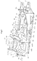
FIG. 1 is a perspective view showing a first embodiment of the invention, showing a swivel frame portion as viewed from the left upper side thereof, -
FIG. 2 is a perspective view showing the swivel frame portion as viewed from the right upper side thereof, -
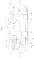
FIG. 3 is a plane view showing the swivel frame portion, -
FIG. 4 is a left side view showing the swivel frame portion, -
FIG.5 is a rear view showing the swivel frame portion, -
FIG. 6 is a side view of a backhoe, - Next, embodiments of the present invention will be described with reference to the accompanying drawings.
- In
FIG. 6 , in aswivel work machine 1, which is a backhoe, atraveling device 3 having a pair of right and left crawlertraveling bodies 2 mounts thereon aswivel deck 5 that is swivellable about a vertical swivel axis X via a swivel bearing 4. At the front end of thisswivel deck 5, there is attached anexcavator 6. - On a rear portion of the
swivel deck 5, there is mounted a hood 9, forwardly of which there is provided amaneuvering section 13 having a driver'sseat 10, amaneuvering lever 11, amaneuvering pedal 12, etc. Incidentally, on theswivel deck 5, a rollover protection device such as a ROPS, or a cabin is mounted to surround themaneuvering section 13. - Forwardly of the
traveling device 3, adozer 15 is provided. At a front portion of theswivel deck 5, there are provided a pair of upper andlower support brackets 17 comprised of plate members configured to support theexcavator 6. - The
excavator 6 includes aswing bracket 18 supported to the upper andlower support brackets 17 to be pivotable to the right and left about a vertical axis, aboom 21 having a base portion connected to theswing bracket 18 to be vertically pivotable about a right/left axis, anarm 22 connected to the leading end of theboom 21 to be pivotable in the fore/aft direction about a right/left axis, and abucket 23 pivotally connected to the leading end of thisarm 22 to be pivotable about a right/left axis. - The
swing bracket 18 is pivotable in response to expansion/contraction of a swing cylinder disposed on the right side within theswivel deck 5. Theboom 21 is pivotable in response to expansion/contraction of aboom cylinder 25 interposed between theboom 21 and the swing bracket. Thebucket 23 is pivotable in response to expansion/contraction of abucket cylinder 27 interposed between thebucket 23 and thearm 22. The swing cylinder, theboom cylinder 25, thearm cylinder 26 and thebucket cylinder 27 are comprised of hydraulic cylinders. - As shown in
FIG. 1 through FIG. 5 , theswivel deck 5 includes aswivel frame 31 acting as a framework, a protector rear portion 32 (seeFIG. 6 ) fixedly attached to the rear portion of theswivel frame 31 and constituting the rear portion of theswivel deck 5, and a pair of right and leftprotector side portions 33 provided on the right and left opposed sides of the protectorrear portion 32 and constituting the rear portion of theswivel deck 5 together with the protectorrear portion 32. The right and left sides of theswivel deck 5 are covered withcover members 34 and the front face of the deck is covered with another cover member. - As shown in
FIG. 3 , rearwardly of theswivel deck 5, an engine room is formed, and on a rear portion of theswivel frame 31, anengine 35 is mounted. - As shown in
FIG. 6 , a hood 9 covers theengine 35. This hood 9 includes afront cover 37 which partitions between theengine 35 and the driver'sseat 10 disposed forwardly of theengine 35 and covers theengine 35 from above, a hoodrear portion 38 which is disposed upwardly of the protectorrear portion 32 and covers the rear side of theengine 35, and a pair of right and lefthood side portions 39 which are disposed upwardly of theprotector side portions 33 and cover the side portions of theengine 35. - As shown in
FIG. 1 through FIG. 5 , inside the hood 9, asupport frame 46 havinglegs upper plate 45 is disposed in such a manner as to bridge over theengine 35. Abattery 48 is mounted at a rear left side of theswivel frame 31 inside the hood 9. Aradiator 49, etc. are disposed on the right side of thebattery 49. Anair cleaner 51 is disposed upwardly of theengine 35. - Further, on the
swivel frame 31, there are mounted the driver'sseat 10, afuel tank 53, awork oil tank 54, acontrol valve 55, etc. Thecontrol valve 55 comprises interconnected assembly of control valves for controlling various hydraulic instruments provided in theswivel work machine 1. - The
swivel frame 31 includes aswivel base plate 57 comprised of a plate member constituting a bottom wall of theswivel deck 5, the pair of upper andlower support brackets 17 projecting forwardly from the front end of theswivel base plate 57 and supporting theexcavator 6, apartition wall 59 partitioning the space forwardly of theengine 35 in the fore/aft direction, and a pair of right and leftvertical ribs swivel base plate 57 for interconnecting thesupport bracket 17 and thepartition wall 59. The pair ofvertical ribs support bracket 17 to an intermediate portion on the rear side and the respective rear sides thereof extend parallel with each other rearward and the rear ends thereof are fixedly attached to thepartition wall 59 by means of welding or the like. - To the upper end portion of the
partition wall 59, the lower end portion of thefront cover 37 is fixedly connected. Further, at an upper portion of thepartition wall 59, there is formed astep attaching plate 60 projecting forwardly therefrom. A rear end portion of astep 65 is fixedly attached to thestep attaching plate 60 and is fixedly mounted on a plurality of step supportingcylindrical bodies 64. As shown by chain lines inFIG. 4 , thestep 65 is disposed upwardly of theswivel base plate 57. - On the
swivel base plate 57 and forwardly of thefuel tank 53, there is provided acylinder attaching portion 72 for the swing cylinder. On the opposed lateral sides of theswivel base plate 57, thee are provided attachingplates pieces side cover members 34 of theswivel frame 31 are attached. On theswivel base plate 57 and forwardly of thestep attaching plate 60, there are provided atank attaching plate 80 for receiving and supporting thefuel tank 53 and aposition setting portion 80A for setting the position of thefuel tank 53 in the left direction and the fore/aft direction at the back side thereof. - The
fuel tank 53 is detachably inserted from the right side of theswivel deck 5 and is mounted on thetank attaching plate 80 and the projecting portion at the back side thereof is engaged in ahole 80a defined in theposition setting member 80A and prevented against inadvertent withdrawal thereof by a stopper tool (not shown). At a rear upper portion of the right vertical rib 61, there is formed a receivingrecess portion 68 for receiving and supporting the right side portion of thefuel tank 53. Incidentally, thework oil tank 54 is disposed on the left side of thefront plate portion 67 and on the left side relative to the leftvertical rib 61L. Instead, this disposing may be replaced with the disposing of thefuel tank 53. - The
swivel base plate 57 is supported to the travelingdevice 3 via the swivel bearing 4 to be pivotable about the vertical swivel axis X. Further, at the swivel center of theswivel base plate 57, there is formed acircular insertion hole 63 through which the upper portion of the swivel joint is to be inserted. The swivel joint feeds pressure oil from thecontrol valve 55 on theswivel deck 5 side to the hydraulic instruments on the travelingdevice 3 side. On the right side of theinsertion hole 63, there is provided a swivelmotor attaching portion 84. - The
swivel base plate 57 is divided, on its rear side and its front side, between arear plate portion 66 and afront plate portion 67. Therear plate portion 66 is formed of a plate thinner than thefront plate portion 67 and is fixedly connected to thefront plate portion 67 in such a manner that the upper surfaces thereof are flush with each other. - The
swivel base plate 57 has an approximately rectangular shape in its plane view, and on its upper surface, there are provided erect, such components as thesupport bracket 17, thevertical ribs cylinder attaching portion 72, etc. And, to the lower surface, the swivel bearing 4 is fixedly attached. Thus, theswivel base plate 57 is constructed as a sturdy structure for supporting the load from theexcavator 6. - The rear portion of the
front plate portion 67 of theswivel base plate 57 projects more rearwardly than thepartition wall 59, and the lower end of thepartition wall 59 is fixedly attached to the rear portion of thefront plate portion 67 by means of welding or the like. On therear plate portion 66 of theswivel base plate 57, the right and leftvertical walls vertical walls rear plate portion 66 and are fixedly attached to the rear portion of thefront plate portion 67 and thepartition wall 59 by means of welding or the like. - The rear end of the
rear plate portion 66 is bent upward to form anerect wall 70 as an erect portion, to which the rear ends of the pair ofvertical walls - The
erect wall 70 is disposed parallel with thepartition wall 59, and thevertical walls rear plate portion 66 to thefront plate portion 67. - At the front and rear opposed ends of the pair of right and left
vertical walls engine mounting portion 71a, a right frontengine mounting portion 71b, a left rearengine mounting portion 71c, a right rearengine mounting portion 71d). Eachengine mounting portion 71 is formed of an upper end portion of thevertical wall engine mounting portions partition wall 59 by means of welding or the like. The rear ends of the rearengine mounting portions erect wall 70 by means of welding or the like. Theengine 35 is fixedly mounted on the fourengine mounting portions 71. - The protector
rear portion 32 is disposed so as to cover the rear side of theerect wall 70 and the protectorrear portion 32 is fixed to theerect wall 70 by means of a fastener or the like. As shown by the chain lines inFIG. 5 , on the opposed lateral sides of the protectorrear portion 32, theprotector side portions 33 are disposed. The rightprojector side portion 33 is attached to a fixedrack 90 which is fixed to the right end of therear plate portion 66 whereas the leftprotector side portion 33 is openable and closable for allowing inspection of thebattery 48, theradiator 49. - As shown in
FIG. 3 , the connecting portion of the rear end of the leftvertical rib 61L (i.e. the fixedly attaching portion by means of welding or the like) and the fixedly attaching portion of the leftengine mounting portion 71a of the leftvertical wall 69L to thepartition wall 59 are overlapped with each other in the right/left direction. And, the connecting portion of the rear end of the rightvertical rib 61R (i.e. the fixedly attaching portion by means of welding or the like) and the fixedly attaching portion of the rightengine mounting portion 71b of the rightvertical wall 69R to thepartition wall 59 are overlapped with each other in the right/left direction. - As shown in
FIG. 5 , to the left outer side of the leftvertical wall 69L, there is provided an attachingrod 73 and this attachingrod 73 is connected and fixed between thepartition wall 59 and theerect wall 70 upwardly of theswivel base plate 57. And, to this attachingrod 73, aradiator mounting rack 79 is fixed by means of a fastener such as a bolt. And, on thisradiator mounting rack 79, theradiator 49 is mounted. - As shown in
FIG. 1 through FIG. 5 , from the rear face of thepartition wall 59, there are formed a pair of right and leftleg mounting racks erect wall 70, a rearleg mounting rack 79 is formed to project rearward therefrom. The lower ends of thelegs support frame 46 are fixed respectively to the pair of frontleg mounting racks leg 44 of thesupport frame 46 is fixed to the rearleg mounting rack 79 by means of fasteners such as bolts. - The upper ends of the three
legs upper plate 45, thus providing attaching of the rear upper portion of thefront cover 37 and the attaching of the pivot shaft for the front upper portion of the hoodrear portion 38. Moreover, theupper plate 45 functions as a mounting rack for the ROPS or a mounting rack for the rear portion of the cabin. - The
rear plate portion 66 of theswivel base plate 57 defines anopening 81 at a position corresponding to theengine 35 and at the rear end portion of therear plate portion 66, there are provided a pair of right and leftopenings erect wall 70. Further, in thefront plate portion 67 of theswivel base plate 57, in addition to theinsertion hole 63 described hereinbefore, there are providedopenings fuel tank 53, thework oil tank 54, and thecontrol valve 55. With these openings, the weight of theswivel base plate 57 is reduced. Theseopenings - According to the foregoing embodiment, the
swivel base plate 57 is divided at its rear side and its front side, between therear plate portion 66 and thefront plate portion 67 and therear plate portion 66 is formed of a plate thinner than thefront plate portion 67 and is fixedly connected thereto in such a manner that the upper surfaces thereof are flush with each other. By forming therear plate portion 66 of theswivel base plate 57 of a thin plate, the weight of the component can be reduced and also the manufacture cost can be reduced. Moreover, the rear portion of therear plate portion 67 of theswivel base plate 57 projects more rearward than thepartition wall 59 and on therear plate portion 66 of theswivel base plate 57, the pair of right and leftvertical walls vertical walls rear plate portion 66 and are fixedly attached to the rear portion of thefront plate portion 67 and to thepartition wall 59. Therefore, with the connection between therear plate portion 66 and thefront plate portion 67 and the fixed attachment of the pair ofvertical walls front plate portion 67 and to thepartition wall 59, the connection and fixing between therear plate portion 66 side and thefront plate portion 67 side can be rendered strong. - Further, from the rear end of the
rear plate portion 66, theerect wall 70 is formed as an upwardly bent portion and the rear ends of the pair ofvertical walls erect wall 70. Therefore, simultaneously with the fixed attachment of the front portions of the pair ofvertical walls rear plate portion 66 to thefront plate portion 67 and thepartition wall 59, the rear ends of the pair ofvertical walls erect wall 70 formed integral with therear plate portion 66. Therefore, the rear portion of theswivel base plate 57 can be further reinforced. - Further, the
engine mounting portions 71 are formed at the front and rear end portions of the pair of right and leftvertical walls engine mounting portions partition wall 59 and the rear ends of the rearengine mounting portions erect wall 70. Therefore, the pair ofvertical walls partition wall 59 and theerect wall 70 via theengine mounting portions 71. Thus, through the effective utilization of theengine mounting portions 71, the rear portion of theswivel base plate 57 can be further reinforced. - Moreover, the connecting portion of the rear end of the left
vertical rib 61L to thepartition wall 59 and the fixedly attaching portion of the leftvertical wall 69L to thepartition wall 59 of theengine mounting portion 71a are overlapped with each other in the right/left direction, and the connecting portion of the rear end of the rightvertical rib 61R to thepartition wall 59 and the fixedly attaching portion of the rightvertical wall 69R to thepartition wall 59 of theengine mounting portion 71b are overlapped with each other in the right/left direction. Therefore, via thepartition wall 59, the rear end of the leftvertical rib 61L and the leftengine mounting portion 71a and the leftvertical wall 69L can be fixedly connected to each other. And, via thepartition wall 59, the rear end of the rightvertical rib 61R and the rightengine mounting portion 71b and the rightvertical wall 69R can be fixedly connected to each other. Thus, the connecting and fixing between therear plate portion 66 side and thefront plate portion 67 side can be further reinforced.
Claims (4)
- A swivel frame for a swivel work machine, with:a swivel base plate (57) supportable on a traveling machine body (3) to be pivotable about a swivel axis (X) and mounting an engine (35) at a rear portion thereofa support bracket (17) provided at a front end of the swivel base plate (57) for supporting excavating implement (6);a partition wall (59) provided on the swivel base plate (57) for partitioning space forwardly of the engine (35) in the fore/aft direction; anda pair of right and left vertical ribs (61L, 61R) provided on the swivel base plate (57) for interconnecting the support bracket (17) and the partition wall (59);said swivel base plate (57) being divided into a rear plate portion (66) on the rear side thereof and a front plate portion (67) on the front side thereof, a pair of vertical walls (69L, 69R) being formed on and project from said rear plate portion (66); characterised in that the rear plate portion (66) is formed of a plate thinner than the front plate portion (67);said rear plate portion (66) and said front plate portion (67) are fixedly connected to each other in such in a manner that upper surfaces thereof are flush with each other;a rear portion of said front plate portion (67) projects more rearward than said partition wall (59); and front portions (69LF, 69RF) of said pair of vertical walls (69L, 69R) project more forward than said rear plate portion (66) and are fixedly attached to the rear portion of said front plate portion (67) and said partition wall (59).
- The swivel frame for a swivel work machine according to claim 1, characterized in that a rear end of said rear plate portion (66) is bent to form an erect wall (70), to which rear ends of said vertical walls (69L, 69R) are fixedly attached.
- The swivel frame for a swivel work machine according to claim 2, characterized in that at front and rear opposed ends of said pair of right and left vertical walls (69L, 69R), there are formed engine mounting portions (71), with a front end of the front engine mounting portion (71) being fixedly attached to said partition wall (59) and with a rear end of the rear engine mounting portion (71) being fixedly attached to said erect wall (70).
- The swivel frame for a swivel work machine according to claim 3, characterized in that a connecting portion of the left vertical rib (61L) to be connected to said partition wall (59) and a fixedly attaching portion of the engine mounting portion (71) of the left vertical wall (69L) to be fixedly attached to said partition wall (59) are overlapped with each other in the right/left direction; and
a connecting portion of the right vertical rib (61R) to be connected to said partition wall (59) and a fixedly attaching portion of the engine mounting portion (71) of the right vertical wall (69R) to be fixedly attached to said partition wall (59) are overlapped with each other in the right/left direction.
Applications Claiming Priority (3)
| Application Number | Priority Date | Filing Date | Title |
|---|---|---|---|
| JP2009224700A JP5100732B2 (en) | 2009-09-29 | 2009-09-29 | Swing frame of swivel work machine |
| JP2009247718 | 2009-10-28 | ||
| JP2009265280A JP5537910B2 (en) | 2009-10-28 | 2009-11-20 | Swivel work machine |
Publications (2)
| Publication Number | Publication Date |
|---|---|
| EP2302140A1 EP2302140A1 (en) | 2011-03-30 |
| EP2302140B1 true EP2302140B1 (en) | 2018-02-14 |
Family
ID=43447368
Family Applications (1)
| Application Number | Title | Priority Date | Filing Date |
|---|---|---|---|
| EP10179006.1A Active EP2302140B1 (en) | 2009-09-29 | 2010-09-23 | Swivel frame |
Country Status (2)
| Country | Link |
|---|---|
| US (1) | US8267217B2 (en) |
| EP (1) | EP2302140B1 (en) |
Families Citing this family (10)
| Publication number | Priority date | Publication date | Assignee | Title |
|---|---|---|---|---|
| JP5404680B2 (en) * | 2011-03-17 | 2014-02-05 | 日立建機株式会社 | Hydraulic oil tank mounting structure for construction machinery |
| JP2013087455A (en) * | 2011-10-14 | 2013-05-13 | Kobelco Contstruction Machinery Ltd | Work machine |
| NL2008634C2 (en) * | 2012-04-13 | 2013-10-16 | Hudson Bay Holding B V | MOBILE DEVICE. |
| USD686252S1 (en) * | 2012-05-10 | 2013-07-16 | Hitachi Construction Machinery Co., Ltd. | Frame for a construction machine |
| JP6028588B2 (en) * | 2013-01-22 | 2016-11-16 | コベルコ建機株式会社 | Work machine |
| JP6145029B2 (en) * | 2013-11-12 | 2017-06-07 | キャタピラー エス エー アール エル | Construction machinery |
| JP6236425B2 (en) * | 2015-09-30 | 2017-11-22 | 株式会社クボタ | Working machine |
| DK178988B1 (en) * | 2015-12-15 | 2017-07-31 | Staal Ind Ivs | Selvkørende universalkøretøj |
| CN108468361B (en) * | 2018-03-26 | 2021-05-11 | 徐州徐工矿山机械有限公司 | Integrally assembled power cabin of super-tonnage hydraulic excavator |
| US12553214B2 (en) | 2023-12-01 | 2026-02-17 | Kubota Corporation | Working machine |
Family Cites Families (16)
| Publication number | Priority date | Publication date | Assignee | Title |
|---|---|---|---|---|
| US5042602A (en) * | 1989-08-18 | 1991-08-27 | Toyo Umpanki Co., Ltd. | Loader |
| JP3859043B2 (en) * | 1998-07-15 | 2006-12-20 | 株式会社小松製作所 | Swivel frame in small swing hydraulic excavator |
| JP2001040706A (en) * | 1999-08-03 | 2001-02-13 | Komatsu Ltd | Turntable for construction machinery |
| JP2003041626A (en) * | 2001-08-01 | 2003-02-13 | Hitachi Constr Mach Co Ltd | Slewing construction machinery |
| JP4211919B2 (en) * | 2003-03-24 | 2009-01-21 | 株式会社小松製作所 | Hydraulic excavator counterweight |
| JP3956907B2 (en) * | 2003-06-24 | 2007-08-08 | コベルコ建機株式会社 | Small excavator |
| JP4120530B2 (en) * | 2003-08-21 | 2008-07-16 | コベルコ建機株式会社 | How to install support pillars for construction machinery |
| JP4236550B2 (en) | 2003-09-29 | 2009-03-11 | 株式会社クボタ | Tank mounting structure for swivel work machine |
| JP2005271602A (en) * | 2004-03-22 | 2005-10-06 | Komatsu Ltd | Construction machinery |
| JP4459027B2 (en) | 2004-11-19 | 2010-04-28 | 株式会社クボタ | Swivel work machine |
| JP4381287B2 (en) | 2004-11-19 | 2009-12-09 | 株式会社クボタ | Swivel work machine |
| KR100693978B1 (en) * | 2004-11-19 | 2007-03-12 | 가부시끼 가이샤 구보다 | Turning machine |
| JP4619168B2 (en) * | 2005-03-28 | 2011-01-26 | 株式会社クボタ | Swivel work machine |
| KR100689293B1 (en) * | 2005-07-25 | 2007-03-02 | 볼보 컨스트럭션 이키프먼트 홀딩 스웨덴 에이비 | Upper frame structure supporting the cab of the construction machine |
| US7503419B2 (en) * | 2005-09-26 | 2009-03-17 | Kubota Corporation | Backhoe |
| KR100910169B1 (en) * | 2007-07-04 | 2009-07-31 | 볼보 컨스트럭션 이키프먼트 홀딩 스웨덴 에이비 | Top frame of excavator |
-
2010
- 2010-09-21 US US12/886,875 patent/US8267217B2/en active Active
- 2010-09-23 EP EP10179006.1A patent/EP2302140B1/en active Active
Non-Patent Citations (1)
| Title |
|---|
| None * |
Also Published As
| Publication number | Publication date |
|---|---|
| US20110074182A1 (en) | 2011-03-31 |
| EP2302140A1 (en) | 2011-03-30 |
| US8267217B2 (en) | 2012-09-18 |
Similar Documents
| Publication | Publication Date | Title |
|---|---|---|
| US8267217B2 (en) | Swivel frame | |
| CN101283144B (en) | Construction machine | |
| KR20030006924A (en) | Frame type tractor | |
| JP5009933B2 (en) | Wheel loader | |
| EP1659225B1 (en) | Swiveling work machine | |
| EP2565331B1 (en) | Device-supporting member and upper slewing body having the same | |
| US12352008B2 (en) | Working machine | |
| CN203049665U (en) | Upper frame of engineering machinery | |
| EP2960380B1 (en) | Construction machine | |
| KR101837220B1 (en) | Construction machine swing frame | |
| JP2006144456A (en) | Swivel work machine | |
| JP5100732B2 (en) | Swing frame of swivel work machine | |
| JP2011230693A (en) | Tractor | |
| JP3697370B2 (en) | Swivel work machine | |
| JP4327658B2 (en) | Construction machinery cab | |
| JP4199173B2 (en) | Swivel construction machine | |
| EP1754835A1 (en) | Canopy installation structure in working vehicle | |
| JP3917448B2 (en) | Tractor front guard device | |
| JP3679311B2 (en) | Swivel work machine | |
| JP2008063812A (en) | Construction machine console box mounting structure | |
| KR20080030478A (en) | Valve installation structure and loader worker to loader worker | |
| JP4619170B2 (en) | Swivel work machine | |
| JP2004116048A (en) | Work machine | |
| JP3718428B2 (en) | Pilot valve mounting structure | |
| JP2005336829A (en) | Revolving frame for construction machine |
Legal Events
| Date | Code | Title | Description |
|---|---|---|---|
| PUAI | Public reference made under article 153(3) epc to a published international application that has entered the european phase |
Free format text: ORIGINAL CODE: 0009012 |
|
| 17P | Request for examination filed |
Effective date: 20101013 |
|
| AK | Designated contracting states |
Kind code of ref document: A1 Designated state(s): AL AT BE BG CH CY CZ DE DK EE ES FI FR GB GR HR HU IE IS IT LI LT LU LV MC MK MT NL NO PL PT RO SE SI SK SM TR |
|
| AX | Request for extension of the european patent |
Extension state: BA ME RS |
|
| REG | Reference to a national code |
Ref country code: DE Ref legal event code: R079 Ref document number: 602010048458 Country of ref document: DE Free format text: PREVIOUS MAIN CLASS: E02F0009080000 Ipc: B62D0033060000 |
|
| GRAP | Despatch of communication of intention to grant a patent |
Free format text: ORIGINAL CODE: EPIDOSNIGR1 |
|
| RIC1 | Information provided on ipc code assigned before grant |
Ipc: E02F 3/32 20060101ALI20170801BHEP Ipc: E02F 9/08 20060101ALI20170801BHEP Ipc: B62D 33/06 20060101AFI20170801BHEP Ipc: B62D 33/063 20060101ALI20170801BHEP |
|
| INTG | Intention to grant announced |
Effective date: 20170814 |
|
| GRAS | Grant fee paid |
Free format text: ORIGINAL CODE: EPIDOSNIGR3 |
|
| GRAA | (expected) grant |
Free format text: ORIGINAL CODE: 0009210 |
|
| AK | Designated contracting states |
Kind code of ref document: B1 Designated state(s): AL AT BE BG CH CY CZ DE DK EE ES FI FR GB GR HR HU IE IS IT LI LT LU LV MC MK MT NL NO PL PT RO SE SI SK SM TR |
|
| REG | Reference to a national code |
Ref country code: GB Ref legal event code: FG4D |
|
| REG | Reference to a national code |
Ref country code: CH Ref legal event code: EP |
|
| REG | Reference to a national code |
Ref country code: IE Ref legal event code: FG4D |
|
| REG | Reference to a national code |
Ref country code: DE Ref legal event code: R096 Ref document number: 602010048458 Country of ref document: DE Ref country code: AT Ref legal event code: REF Ref document number: 969664 Country of ref document: AT Kind code of ref document: T Effective date: 20180315 |
|
| REG | Reference to a national code |
Ref country code: NL Ref legal event code: MP Effective date: 20180214 |
|
| REG | Reference to a national code |
Ref country code: AT Ref legal event code: MK05 Ref document number: 969664 Country of ref document: AT Kind code of ref document: T Effective date: 20180214 |
|
| PG25 | Lapsed in a contracting state [announced via postgrant information from national office to epo] |
Ref country code: LT Free format text: LAPSE BECAUSE OF FAILURE TO SUBMIT A TRANSLATION OF THE DESCRIPTION OR TO PAY THE FEE WITHIN THE PRESCRIBED TIME-LIMIT Effective date: 20180214 Ref country code: CY Free format text: LAPSE BECAUSE OF FAILURE TO SUBMIT A TRANSLATION OF THE DESCRIPTION OR TO PAY THE FEE WITHIN THE PRESCRIBED TIME-LIMIT Effective date: 20180214 Ref country code: NL Free format text: LAPSE BECAUSE OF FAILURE TO SUBMIT A TRANSLATION OF THE DESCRIPTION OR TO PAY THE FEE WITHIN THE PRESCRIBED TIME-LIMIT Effective date: 20180214 Ref country code: HR Free format text: LAPSE BECAUSE OF FAILURE TO SUBMIT A TRANSLATION OF THE DESCRIPTION OR TO PAY THE FEE WITHIN THE PRESCRIBED TIME-LIMIT Effective date: 20180214 Ref country code: NO Free format text: LAPSE BECAUSE OF FAILURE TO SUBMIT A TRANSLATION OF THE DESCRIPTION OR TO PAY THE FEE WITHIN THE PRESCRIBED TIME-LIMIT Effective date: 20180514 Ref country code: FI Free format text: LAPSE BECAUSE OF FAILURE TO SUBMIT A TRANSLATION OF THE DESCRIPTION OR TO PAY THE FEE WITHIN THE PRESCRIBED TIME-LIMIT Effective date: 20180214 Ref country code: ES Free format text: LAPSE BECAUSE OF FAILURE TO SUBMIT A TRANSLATION OF THE DESCRIPTION OR TO PAY THE FEE WITHIN THE PRESCRIBED TIME-LIMIT Effective date: 20180214 |
|
| PG25 | Lapsed in a contracting state [announced via postgrant information from national office to epo] |
Ref country code: AT Free format text: LAPSE BECAUSE OF FAILURE TO SUBMIT A TRANSLATION OF THE DESCRIPTION OR TO PAY THE FEE WITHIN THE PRESCRIBED TIME-LIMIT Effective date: 20180214 Ref country code: SE Free format text: LAPSE BECAUSE OF FAILURE TO SUBMIT A TRANSLATION OF THE DESCRIPTION OR TO PAY THE FEE WITHIN THE PRESCRIBED TIME-LIMIT Effective date: 20180214 Ref country code: LV Free format text: LAPSE BECAUSE OF FAILURE TO SUBMIT A TRANSLATION OF THE DESCRIPTION OR TO PAY THE FEE WITHIN THE PRESCRIBED TIME-LIMIT Effective date: 20180214 Ref country code: BG Free format text: LAPSE BECAUSE OF FAILURE TO SUBMIT A TRANSLATION OF THE DESCRIPTION OR TO PAY THE FEE WITHIN THE PRESCRIBED TIME-LIMIT Effective date: 20180514 Ref country code: GR Free format text: LAPSE BECAUSE OF FAILURE TO SUBMIT A TRANSLATION OF THE DESCRIPTION OR TO PAY THE FEE WITHIN THE PRESCRIBED TIME-LIMIT Effective date: 20180515 |
|
| REG | Reference to a national code |
Ref country code: FR Ref legal event code: PLFP Year of fee payment: 9 |
|
| PG25 | Lapsed in a contracting state [announced via postgrant information from national office to epo] |
Ref country code: AL Free format text: LAPSE BECAUSE OF FAILURE TO SUBMIT A TRANSLATION OF THE DESCRIPTION OR TO PAY THE FEE WITHIN THE PRESCRIBED TIME-LIMIT Effective date: 20180214 Ref country code: RO Free format text: LAPSE BECAUSE OF FAILURE TO SUBMIT A TRANSLATION OF THE DESCRIPTION OR TO PAY THE FEE WITHIN THE PRESCRIBED TIME-LIMIT Effective date: 20180214 Ref country code: EE Free format text: LAPSE BECAUSE OF FAILURE TO SUBMIT A TRANSLATION OF THE DESCRIPTION OR TO PAY THE FEE WITHIN THE PRESCRIBED TIME-LIMIT Effective date: 20180214 Ref country code: PL Free format text: LAPSE BECAUSE OF FAILURE TO SUBMIT A TRANSLATION OF THE DESCRIPTION OR TO PAY THE FEE WITHIN THE PRESCRIBED TIME-LIMIT Effective date: 20180214 Ref country code: IT Free format text: LAPSE BECAUSE OF FAILURE TO SUBMIT A TRANSLATION OF THE DESCRIPTION OR TO PAY THE FEE WITHIN THE PRESCRIBED TIME-LIMIT Effective date: 20180214 |
|
| REG | Reference to a national code |
Ref country code: DE Ref legal event code: R097 Ref document number: 602010048458 Country of ref document: DE |
|
| PG25 | Lapsed in a contracting state [announced via postgrant information from national office to epo] |
Ref country code: SM Free format text: LAPSE BECAUSE OF FAILURE TO SUBMIT A TRANSLATION OF THE DESCRIPTION OR TO PAY THE FEE WITHIN THE PRESCRIBED TIME-LIMIT Effective date: 20180214 Ref country code: SK Free format text: LAPSE BECAUSE OF FAILURE TO SUBMIT A TRANSLATION OF THE DESCRIPTION OR TO PAY THE FEE WITHIN THE PRESCRIBED TIME-LIMIT Effective date: 20180214 Ref country code: DK Free format text: LAPSE BECAUSE OF FAILURE TO SUBMIT A TRANSLATION OF THE DESCRIPTION OR TO PAY THE FEE WITHIN THE PRESCRIBED TIME-LIMIT Effective date: 20180214 Ref country code: CZ Free format text: LAPSE BECAUSE OF FAILURE TO SUBMIT A TRANSLATION OF THE DESCRIPTION OR TO PAY THE FEE WITHIN THE PRESCRIBED TIME-LIMIT Effective date: 20180214 |
|
| PLBE | No opposition filed within time limit |
Free format text: ORIGINAL CODE: 0009261 |
|
| STAA | Information on the status of an ep patent application or granted ep patent |
Free format text: STATUS: NO OPPOSITION FILED WITHIN TIME LIMIT |
|
| 26N | No opposition filed |
Effective date: 20181115 |
|
| PG25 | Lapsed in a contracting state [announced via postgrant information from national office to epo] |
Ref country code: SI Free format text: LAPSE BECAUSE OF FAILURE TO SUBMIT A TRANSLATION OF THE DESCRIPTION OR TO PAY THE FEE WITHIN THE PRESCRIBED TIME-LIMIT Effective date: 20180214 |
|
| PG25 | Lapsed in a contracting state [announced via postgrant information from national office to epo] |
Ref country code: MC Free format text: LAPSE BECAUSE OF FAILURE TO SUBMIT A TRANSLATION OF THE DESCRIPTION OR TO PAY THE FEE WITHIN THE PRESCRIBED TIME-LIMIT Effective date: 20180214 |
|
| REG | Reference to a national code |
Ref country code: CH Ref legal event code: PL |
|
| REG | Reference to a national code |
Ref country code: BE Ref legal event code: MM Effective date: 20180930 |
|
| REG | Reference to a national code |
Ref country code: IE Ref legal event code: MM4A |
|
| PG25 | Lapsed in a contracting state [announced via postgrant information from national office to epo] |
Ref country code: LU Free format text: LAPSE BECAUSE OF NON-PAYMENT OF DUE FEES Effective date: 20180923 |
|
| PG25 | Lapsed in a contracting state [announced via postgrant information from national office to epo] |
Ref country code: IE Free format text: LAPSE BECAUSE OF NON-PAYMENT OF DUE FEES Effective date: 20180923 |
|
| PG25 | Lapsed in a contracting state [announced via postgrant information from national office to epo] |
Ref country code: BE Free format text: LAPSE BECAUSE OF NON-PAYMENT OF DUE FEES Effective date: 20180930 Ref country code: CH Free format text: LAPSE BECAUSE OF NON-PAYMENT OF DUE FEES Effective date: 20180930 Ref country code: LI Free format text: LAPSE BECAUSE OF NON-PAYMENT OF DUE FEES Effective date: 20180930 |
|
| PG25 | Lapsed in a contracting state [announced via postgrant information from national office to epo] |
Ref country code: MT Free format text: LAPSE BECAUSE OF NON-PAYMENT OF DUE FEES Effective date: 20180923 |
|
| PG25 | Lapsed in a contracting state [announced via postgrant information from national office to epo] |
Ref country code: TR Free format text: LAPSE BECAUSE OF FAILURE TO SUBMIT A TRANSLATION OF THE DESCRIPTION OR TO PAY THE FEE WITHIN THE PRESCRIBED TIME-LIMIT Effective date: 20180214 |
|
| PG25 | Lapsed in a contracting state [announced via postgrant information from national office to epo] |
Ref country code: HU Free format text: LAPSE BECAUSE OF FAILURE TO SUBMIT A TRANSLATION OF THE DESCRIPTION OR TO PAY THE FEE WITHIN THE PRESCRIBED TIME-LIMIT; INVALID AB INITIO Effective date: 20100923 Ref country code: PT Free format text: LAPSE BECAUSE OF FAILURE TO SUBMIT A TRANSLATION OF THE DESCRIPTION OR TO PAY THE FEE WITHIN THE PRESCRIBED TIME-LIMIT Effective date: 20180214 |
|
| PG25 | Lapsed in a contracting state [announced via postgrant information from national office to epo] |
Ref country code: MK Free format text: LAPSE BECAUSE OF NON-PAYMENT OF DUE FEES Effective date: 20180214 |
|
| PG25 | Lapsed in a contracting state [announced via postgrant information from national office to epo] |
Ref country code: IS Free format text: LAPSE BECAUSE OF FAILURE TO SUBMIT A TRANSLATION OF THE DESCRIPTION OR TO PAY THE FEE WITHIN THE PRESCRIBED TIME-LIMIT Effective date: 20180614 |
|
| PGFP | Annual fee paid to national office [announced via postgrant information from national office to epo] |
Ref country code: GB Payment date: 20240801 Year of fee payment: 15 |
|
| PGFP | Annual fee paid to national office [announced via postgrant information from national office to epo] |
Ref country code: FR Payment date: 20240808 Year of fee payment: 15 |
|
| PGFP | Annual fee paid to national office [announced via postgrant information from national office to epo] |
Ref country code: DE Payment date: 20250730 Year of fee payment: 16 |