EP2301723A1 - Guide device, in particular guide device for a lifting element - Google Patents
Guide device, in particular guide device for a lifting element Download PDFInfo
- Publication number
- EP2301723A1 EP2301723A1 EP10170997A EP10170997A EP2301723A1 EP 2301723 A1 EP2301723 A1 EP 2301723A1 EP 10170997 A EP10170997 A EP 10170997A EP 10170997 A EP10170997 A EP 10170997A EP 2301723 A1 EP2301723 A1 EP 2301723A1
- Authority
- EP
- European Patent Office
- Prior art keywords
- unit
- guide
- guide device
- bearing unit
- lifting
- Prior art date
- Legal status (The legal status is an assumption and is not a legal conclusion. Google has not performed a legal analysis and makes no representation as to the accuracy of the status listed.)
- Granted
Links
- 230000008878 coupling Effects 0.000 claims description 12
- 238000010168 coupling process Methods 0.000 claims description 12
- 238000005859 coupling reaction Methods 0.000 claims description 12
- 230000033001 locomotion Effects 0.000 description 19
- 238000003860 storage Methods 0.000 description 10
- 230000000694 effects Effects 0.000 description 3
- 239000000463 material Substances 0.000 description 3
- 238000003466 welding Methods 0.000 description 3
- 230000005540 biological transmission Effects 0.000 description 2
- 150000001875 compounds Chemical class 0.000 description 2
- 239000004744 fabric Substances 0.000 description 2
- 238000007373 indentation Methods 0.000 description 2
- 230000003993 interaction Effects 0.000 description 2
- 230000009471 action Effects 0.000 description 1
- 238000004026 adhesive bonding Methods 0.000 description 1
- 238000005520 cutting process Methods 0.000 description 1
- 230000006735 deficit Effects 0.000 description 1
- 238000009826 distribution Methods 0.000 description 1
- 238000009434 installation Methods 0.000 description 1
- 239000000314 lubricant Substances 0.000 description 1
- 238000000034 method Methods 0.000 description 1
- 230000008569 process Effects 0.000 description 1
- 230000009467 reduction Effects 0.000 description 1
- -1 screwed Chemical class 0.000 description 1
- 238000005245 sintering Methods 0.000 description 1
Images


Classifications
-
- B—PERFORMING OPERATIONS; TRANSPORTING
- B25—HAND TOOLS; PORTABLE POWER-DRIVEN TOOLS; MANIPULATORS
- B25H—WORKSHOP EQUIPMENT, e.g. FOR MARKING-OUT WORK; STORAGE MEANS FOR WORKSHOPS
- B25H1/00—Work benches; Portable stands or supports for positioning portable tools or work to be operated on thereby
- B25H1/0021—Stands, supports or guiding devices for positioning portable tools or for securing them to the work
- B25H1/0078—Guiding devices for hand tools
-
- B—PERFORMING OPERATIONS; TRANSPORTING
- B23—MACHINE TOOLS; METAL-WORKING NOT OTHERWISE PROVIDED FOR
- B23D—PLANING; SLOTTING; SHEARING; BROACHING; SAWING; FILING; SCRAPING; LIKE OPERATIONS FOR WORKING METAL BY REMOVING MATERIAL, NOT OTHERWISE PROVIDED FOR
- B23D49/00—Machines or devices for sawing with straight reciprocating saw blades, e.g. hacksaws
- B23D49/10—Hand-held or hand-operated sawing devices with straight saw blades
- B23D49/16—Hand-held or hand-operated sawing devices with straight saw blades actuated by electric or magnetic power or prime movers
- B23D49/162—Pad sawing devices
- B23D49/165—Pad sawing devices with means to move the saw blades in an orbital path
-
- B—PERFORMING OPERATIONS; TRANSPORTING
- B23—MACHINE TOOLS; METAL-WORKING NOT OTHERWISE PROVIDED FOR
- B23D—PLANING; SLOTTING; SHEARING; BROACHING; SAWING; FILING; SCRAPING; LIKE OPERATIONS FOR WORKING METAL BY REMOVING MATERIAL, NOT OTHERWISE PROVIDED FOR
- B23D51/00—Sawing machines or sawing devices working with straight blades, characterised only by constructional features of particular parts; Carrying or attaching means for tools, covered by this subclass, which are connected to a carrier at both ends
- B23D51/02—Sawing machines or sawing devices working with straight blades, characterised only by constructional features of particular parts; Carrying or attaching means for tools, covered by this subclass, which are connected to a carrier at both ends of beds; of guiding arrangements for work-tables or saw carriers; of frames
Definitions
- a guide device in particular a Hubelement arrangementsvoriques, for a power tool, which has a guide unit which is pivotally mounted about a pendulum axis and is provided for guiding at least one lifting element in a stroke direction.
- a guide device in particular a Hubelement arrangementsvoriques, proposed for a hand tool, with at least one guide unit to guide at least one lifting element in a stroke direction, wherein the guide unit is pivotally mounted about a pendulum axis and wherein the lifting element guided by at least a first bearing unit along the guide unit is.
- a "guide unit” should be understood to mean in particular a unit which specifies a direction of movement, in particular of a lifting element, during a movement process of a lifting movement.
- the guide unit can be provided to restrict a movement of the lifting element, which differs from the preferred direction of movement or from a stroke direction.
- the guide unit is designed, for example, as a pendulum element and / or a rocker.
- the guide unit may be formed in one or more parts, wherein in a multi-part design, the guide unit partially disassembled is.
- the guide unit preferably has a guide element, wherein a "guide element" is to be understood in particular an element, such as a web, a rod, a boundary of a recess and / or any other, the skilled person appear appropriate design.
- this guide element has an orientation, which is aligned in particular parallel to the stroke direction, wherein the guide element determines the direction of movement of the lifting element by this orientation.
- a "lifting element” is to be understood as meaning in particular an element, such as a lifting rod, which in at least one operating state of the hand tool machine moves up and down, in particular a continuous upward and downward movement, preferably by a drive means, such as a motor. is driven.
- the lifting element has a tool holder for a tool, such as a saw blade.
- a "pendulum axis” should be understood to mean, in particular, an axis about which the guide unit can be pivoted, in particular in a working mode or cutting operation of the handheld power tool, with “pivoting” in particular rotation about this axis in an angular range of 180 °, preferably 90 ° ° and particularly preferably 30 ° to be understood.
- a “bearing unit” should be understood to mean, in particular, a unit which receives bearing forces of the lifting element and transmits them to the guide unit and / or to a housing, such as a gearbox housing or an outer housing of the handheld power tool.
- the storage unit may be formed in one or more parts, whereby the storage unit is partially disassembled.
- guided is to be understood here in particular as a passive influencing or restriction of the direction of movement of the lifting element.
- the pendulum axis and the bearing of the lifting element can be structurally easily separated from each other, resulting in the absence of impairment of a function of the guide device to an advantageous reduction in installation height of the guide device of the lifting element and the lifting element itself. Furthermore, a space or a gear chamber can be advantageously reduced thereby, which has a direct effect on the size and weight of the power tool.
- the guide unit has at least one running surface.
- a running surface should be understood to mean, in particular, a surface which is in direct contact with at least the first bearing unit or a component of the first bearing unit and / or a portion of this component.
- the guide unit has at least two running surfaces.
- the first bearing unit or the component of the first bearing unit and / or a portion of the component is directly slidably movable on the running surface.
- the tread may alternatively and / or additionally be provided to directly receive the bearing forces of the first bearing unit.
- the at least one running surface is arranged on the guide element of the guide unit and advantageously integrally formed therewith, wherein “integral” here in particular “formed from a cast” and / or “designed as a component” to be understood.
- more than one tread may be provided, with a person skilled in the art selecting a number by design.
- the first bearing unit has at least one connecting element which is oriented substantially perpendicular to the stroke direction and has at least two contact elements corresponding to the guide unit.
- substantially perpendicular is to be understood in particular to mean that the connecting element with an angular deviation of less than plus / minus 15 °, preferably less than plus / minus 5 ° and particularly preferably less than plus / minus 2 ° a reference object, here a perpendicular to the stroke direction, is aligned.
- a "contact element” is to be understood here in particular as an element which has at least one running surface which directly corresponds to the running surface of the guide unit or of the guide element.
- a "connecting element” here represents in particular an element which is in direct contact with at least two regions or guide elements of the guide unit by means of the two contact elements.
- the connecting element connects at least two regions of the guide unit directly to each other via the contact elements, ie without a further intermediate component.
- the two regions of the guide unit in particular each have a running surface and / or preferably extend substantially parallel to the stroke direction.
- the connecting element and the contact element are preferably embodied integrally with one another, wherein "integral” here means in particular that the connecting element can only be separated from the contact element with loss of function of the connection of the two regions of the guide unit.
- the first bearing unit is designed as a sliding bearing unit.
- a sliding bearing unit is to be understood as meaning in particular a unit in which interaction partners are moved past one another directly and / or only past a lubricant layer and / or their relative movement relative to one another is based on sliding friction.
- the sliding bearing unit is preferably formed by the running surface / the running surfaces of the guide unit and the running surface / the running surfaces of the bearing unit or the contact elements.
- the first bearing unit is preferably arranged at an upper end of the lifting element, which points away from a tool holder. Due to the design of the bearing unit as a sliding bearing unit, the bearing unit can be structurally simple and they can be realized cost-effective and space and component saving.
- the guide device has a further bearing unit, which is designed as a sliding bearing unit.
- This slide bearing unit is designed in particular as a linear bearing and preferably has a sintered bushing.
- Alternatively and / or additionally would be an embodiment as a thrust and / or rotary push joint conceivable.
- any other embodiment of the sliding bearing unit which appears to the person skilled in the art to be suitable, in particular based on a self-lubricating principle, would be conceivable.
- the lifting element can be advantageously stored and simultaneously guided linear.
- the further storage unit is arranged stationarily on the guide unit.
- the term "stationary” defines that the further bearing unit is immovable or fixed relative to the guide unit.
- “stationary” here means that the further bearing unit is moved during a movement, such as a pendulum movement of the guide unit, with it, in particular around the pendulum axis.
- the first bearing unit has a receiving element for the lifting element.
- a "receiving element” should be understood to mean, in particular, an element and / or a design which is in direct contact with the lifting element.
- the element or the design is adapted in its or its contour to an outer contour of the lifting element, so that the element or the configuration of at least 10% of an outer contour and / or a circumference the lifting element is arranged or adapted.
- the receiving element is configured, for example, as a U-shaped and / or cup-shaped indentation and / or as a recess with a profile encompassing the lifting element.
- the receiving element and the lifting element are preferably cohesively, positively and / or non-positively connected to each other.
- any type of fabric, form and / or adhesion connection that appears to the person skilled in the art, such as gluing, sintering, welding, screwing, riveting, etc., comes into consideration.
- the fabric, form and / or adhesion are the Lifting element and the first storage unit structurally simple, reliable and component-saving movably arranged together in the stroke direction.
- the first bearing unit has a coupling element, which is intended to be coupled to a motor output of the power tool.
- a coupling element in particular an element that connects the first bearing unit and a motor output, such as an armature shaft, operatively connected to a downstream transmission or pendulum.
- a drive of a motor can be transferred in a structurally simple and reliable manner to the lifting element connected to the first bearing unit.
- a structurally simple and component-saving attachment of the guide device and thus of the lifting element can be advantageously achieved if the guide device has a bearing means which is intended to support the guide unit to a housing of the power tool.
- a bearing means is to be understood as a means which is intended to receive bearing forces of the guide unit and / or to forward it to the housing of the handheld power tool.
- the “housing” in particular an outer housing of the power tool. In general, however, an attachment to another arranged in the power tool housing, such as a gear and / or motor housing, would be possible.
- the pendulum axis is arranged stationary relative to a housing of the power tool.
- the term "stationary” is understood in particular to mean that the pendulum axis is fixed relative to the housing or immovable and in particular axially immovable and / or non-rotatable. Due to the stationary arrangement, a conventional hand-held power tool pendulum motion can be maintained without structural redesign, which advantageously finds a proven functional principle use.
- the lifting element is designed as a hollow body.
- a "hollow body” should be understood to mean in particular a body which has a lateral surface which surrounds or encloses a cavity.
- an outer contour of the hollow body or of the lifting element of any conceivable shape, such as polygonal, square, oval or round, have. Due to the configuration of the invention, a low lifting weight and thus a low leveling compound can be provided, which has an immediate effect on a low total weight of the lifting element. Furthermore, so structurally simple, a cost-saving and lightweight lifting element can be provided.
- a further embodiment of the invention provides a hand tool, in particular a jigsaw, with at least one guide device.
- a hand tool in particular a jigsaw
- at least one guide device In general, however, would be an application of the guide device in any other, the skilled worker as conceivable hand tool, especially with a pendulum drive a lifting element, conceivable.
- FIG. 1 shows a hand tool 14a, in the form of a jigsaw 46a, with a lifting element 18a, such as a lifting rod, which is driven in a working operation of the jigsaw 46a in a continuous upward and downward movement in a direction of movement or lifting direction 20a.
- the drive is effected by a drive 50a driven by a drive motor 48a, both of which are not shown in detail here and are arranged in a housing 42a of the handheld power tool 14a.
- the lifting element 18a has a tool holder 52a, which carries an insert tool 54a in the form of a jigsaw blade 56a.
- the hand tool 14a further comprises a guide device 10a in the form of a Hubelement arrangementsvoriques 12a, with a guide unit 16a to a guide of the lifting element 18a in the lifting direction 20a.
- the guide unit 16a is pivotally mounted on the housing 42a about a relative to the housing 42a of the power tool 14a stationarily arranged pendulum axis 22a and thus formed as a pendulum element 58a.
- the guide unit 16a or the pendulum element 58a on two bearing means 60a which are arranged at a built into the jigsaw 46a state of the guide device 10a on a pointing to a handle 62a of the power tool 14a side 64a of the guide unit 16a.
- the bearing means 60a are formed as recesses, which are penetrated by an axle pin not shown here in detail, which is mounted in the housing 42a schematically indicated here.
- the pendulum element 58a has a rectangular basic shape and four webs 66a extending parallel to the stroke direction 20a.
- the webs 66a are respectively connected at one end 68a, which is arranged at the mounted in the jigsaw 46a state of the guide device 10a on the pendulum axis 22a, via a connecting web 70a, which is perpendicular to the stroke direction 20a.
- the ends 68a opposite ends 72a of the webs 66a are connected via a further connecting web 74a.
- the connecting webs 70a, 74a and the two outer webs 66a thus form the rectangular basic shape.
- the webs 66a are perpendicular to the stroke direction 20a by extending in the lifting direction 20a openings 76a, 78a, 80a spaced apart, wherein the two outer openings 76a, 80a have a same width 82a.
- the central opening 78a has a width 84a which is approximately three times larger than the width of the openings 76a, 80a. In general, however, any width ratio that would appear appropriate to a person skilled in the art would be conceivable here.
- the guide unit 16a also has four guide elements 86a, which are formed by the webs 66a.
- the guiding function of the guide elements 86a is taken over by boundaries 88a of the outer openings 76a, 80a, which extend in a direction parallel to the stroke direction 20a.
- the lifting element 18a is guided by means of a first bearing unit 24a along the guide unit 16a.
- the guide unit 16a has four running surfaces 26a or each guide element 86a has a running surface 26a, via which the guide unit 16a is in direct contact with the first bearing unit 24a.
- the first bearing unit 24a is slidably movable directly on the running surfaces 26a during a movement in the lifting direction 20a.
- the raceways 26a each extend along the boundaries 88a of the outer openings 76a, 80a. In each case two running surfaces 26a are arranged on two boundaries 88a of the openings 76a, 80a, which are opposite each other.
- the first bearing unit 24a on a slide unit 90a which is equipped with a perpendicular to the stroke direction 20a aligned connecting element 28a.
- the sliding unit 90a carries two contact elements 30a corresponding to the guide unit 16a and to the running surfaces 26a, respectively.
- the connecting element 28a serves to bridge a distance 92a from outer edges of the openings 76a, 80a to one another and thus extends over an entire width 94a of the guide unit 16a, wherein the width 94a extends perpendicular to the lifting direction 20a.
- a length 96a of the connecting element 28a in the lifting direction 20a is selected by the person skilled in the art so as to ensure a good fastening of the lifting element 18a and a required stability of the sliding unit 90a.
- the slide unit 90a or the connecting element 28a is arranged on a side 98a of the guide unit 16a, which points to a motor output 40a (FIG. FIG. 3 ).
- a coupling element 38a which is in the form of a perpendicular to the stroke direction 20a extending groove 100a is formed.
- the coupling element 38a is coupled to the motor output 40a in a sawing operation.
- the engine output 40a includes the transmission 50a, in the form of a pendulum gear, and an armature shaft of the drive motor 48a of the power tool 14a.
- the contact elements 30a are, as in FIG. 3 can be seen formed as contact webs 102a, which extend in the lifting direction 20a and have a perpendicular to the stroke direction 20a aligned width 104a.
- This width 104a is on the width 82a of the outer openings 76a, 80a adapted so that the contact elements 30a and the contact webs 102a can engage in the openings 76a, 80a.
- the contact webs 102a have an extension 106a perpendicular to a main extension plane 108a of the guide device 10a, which corresponds to a depth 110a of the webs 66a, the depth 110a being oriented perpendicular to the main extension plane 108a.
- the first bearing unit 24a or the connecting element 28a on the side 114a facing away from the coupling element 38a and at a height of a longitudinal axis 122a of the pendulum element 58a has a lifting element 20a extending in the lifting direction 20a for the lifting element 18a.
- the receiving element 36a is formed as a U-shaped recess 124a and is thereby adapted to a part of an outer periphery 126a of the lifting element 18a.
- the receiving element 36a and the lifting element 18a are connected to one another by means of welding and thus by material engagement, whereby the connecting element 28a and the lifting element 18a are movably arranged together as a sliding unit 90a.
- the lifting element 18a is formed as a hollow body 44a or as a cylinder jacket 128a, which encloses a cavity 130a, and extends in an assembled manner Condition along the opening 78a. Furthermore, the lifting element 18a is movably mounted in the lifting direction 20a via a bearing arrangement 132a.
- the bearing assembly 132a includes the first bearing unit 24a formed as a sliding bearing unit 32a and another bearing unit 34a also formed as a sliding bearing unit 32a.
- the first bearing unit 24a is arranged on an opposite side 134a of the lifting element 18a to the tool holder 52a or on a side 136a of the guide unit 16a facing the pendulum axis 22a.
- the further bearing unit 34a is arranged stationarily on the guide unit 16a, specifically in the further connecting web 74a.
- the further bearing unit 34a is designed as a sintered bushing 138a, whereby the sliding unit 90a or the lifting element 18a and the connecting element 28a are guided linearly with the contact element 30a.
- FIG. 5 is a part of the first bearing unit 24a and the sliding bearing unit 32a schematically as a section along the line VV of FIG. 4 displayed.
- the illustrated contact element 30a of the connecting element 28a has two running surfaces 140a, which correspond to the running surfaces 26a of the guide unit 16a and the guide elements 86a, respectively.
- the sliding bearing unit 32a of the first bearing unit 24a is formed by the running surfaces 26a of the guide unit 16a and the running surfaces 140a of the first bearing unit 24a and the contact elements 30a, respectively. Further, a protrusion 142a of the washer 120a extending across the width 104a of the contact members 30a is seen, which protects the slide unit 90a from twisting in addition to an action of the raceway surfaces 26a, 140a.
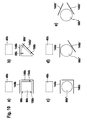
- FIGS. 6 to 15 Alternative embodiments of the guide device 10a are shown. Essentially, the same components, features and functions are always numbered the same. To distinguish the embodiments, however, the letters a to c are added to the reference numerals of the embodiments. The following description is essentially limited to the differences from the embodiment in the FIGS. 1 to 5 , wherein with respect to the same components, features and functions on the description of the embodiment in the FIGS. 1 to 5 can be referenced.
- the FIG. 6 shows an alternative guide device 10b and a Hubelement arrangementsvoruze 12b for a hand tool, in the form of a jigsaw, as shown in the FIG. 1 is shown.
- the guide device 10b has a guide unit 16b for guiding a lifting element 18b, which is designed as a hollow body 44b, in a lifting direction 20b.
- the guide unit 16b is pivotally mounted about a pendulum axis 22b, which is fixed relative to a housing 42b of the power tool, and thus forms a pendulum element 58b.
- the pendulum element 58b has a rectangular basic shape and has two webs 66b, which extend parallel to the lifting direction 20b.
- the webs 66b are connected at an end 68b, which is arranged at the mounted in the jigsaw state of the guide device 10b on the pendulum axis 22b, via a connecting web 70b, which is perpendicular to the lifting direction 20b.
- the ends 68b opposite the ends 68b of the webs 66b are connected via a further connecting web 74b.
- the webs 66b perpendicular to the stroke direction 20b by an opening 78b, which extends in the lifting direction 20b, spaced.
- the webs 66b of the guide unit 16b form guide elements 86b, each having a running surface 26b, wherein the running surfaces 26b are arranged facing each other.
- the first bearing unit 24b is movable directly on the guide unit 16b during a movement in the lifting direction 20b.
- the guide device 10b has a bearing arrangement 132b for a bearing of the lifting element 18b, which is movable in the lifting direction 20b, with a first bearing unit 24b and a further bearing unit 34b. Both bearing units 24b, 34b are each formed as a sliding bearing unit 32b.
- the further bearing unit 34b is designed in the form of a sintered bushing (not shown in detail) and is arranged stationarily on the guide unit 16b or in the further connecting web 74b.
- the first bearing unit 24b is arranged on a side 134b of the lifting element 18b, which lies opposite a tool holder 52b, or on a side 136b of the guide unit 16b, which faces the pendulum axle 22b.
- the lifting element 18b is guided along the guide unit 16b by means of the first bearing unit 24b.
- the first bearing unit 24b as in FIG. 7 1, a sliding unit 90b having a connecting element 28b oriented perpendicular to the lifting direction 20b and the lifting element 18b, whereby the connecting element 28b and the lifting element 18b are movably arranged together in the assembled state and during a lifting movement.
- the connecting element 28b is formed in two parts and has a slider 144b and a receiving member 146b for the lifting element 18b.
- the coupling element 38b is coupled in a sawing operation with a motor output 40b of the power tool.
- the receiving member 146b has a receiving element 36b, which is formed as a cup-shaped indentation 124b, for the lifting element 18b and is thereby adapted to a part of an outer periphery 126b of the lifting element 18b.
- the receiving element 36b and the lifting element 18b are connected to one another by means of welding and thus by material bonding. Other, as the expert appear useful compounds, such as screwed, are possible.
- two contact elements 30b corresponding to the guide unit 16b, in the form of contact webs 102b extending in the lifting direction 20b are integrally formed on the receiving component 146b of the connecting element 28b.
- the contact webs 102b have an extension 106b which is oriented perpendicular to a main extension plane 108b of the guide device 10b and which corresponds to a depth 110b of the webs 66b perpendicular to the main extension plane 108b. Furthermore, the extent 106b corresponds approximately to an outer diameter 148b of the lifting element 18b, so that the contact webs 102a and the webs 66b are flush.
- the slider 144b disposed on a side 98b of the guide unit 16b facing the motor output 40b may abut flat surfaces 150b of the lands 66b, the contact lands 102b and the lifter 18b parallel to the main extension plane 108b Slider 144b show.
- the slider 144b can be easily connected to the lifting member 18b (see FIG FIG. 9 ).
- the contact webs 102b perpendicular to the lifting direction 20b in the installed state are so far apart that a distance 92b of the outer surfaces 152b of the contact webs 102b facing away from the lifting element 18b to a width 84b of the opening 78b, which extends perpendicular to the stroke direction 20b , is adjusted.
- the contact elements 30b and the contact webs 102b can engage in the opening 78b.
- running surfaces 140b of the contact webs 102b formed on the outer surfaces 152b of the contact webs 102b and corresponding to the raceway surfaces 26b of the guide unit 16b are directly adjacent to the raceway surfaces 26a of the guide elements 86b (FIG. FIG. 9 ).
- the slide bearing unit 32b of the first bearing unit 24b is formed by the raceway surfaces 26b of the guide unit 16b and the raceway surfaces 140b of the first bearing unit 24b and the contact elements 30b, respectively, which prevents, in addition to good guidance, a rotation of the slide unit 90b.
- FIG. 10 For example, five alternative arrangements of the guide unit 16b, the slider 144b, and the receiving member 146b are shown schematically by a guide member 86b and a ridge 66b, respectively.
- FIG. 10a the arrangement according to FIG. 9 with a rectangular or square configuration of the web 66b, wherein the slider 144b is disposed on the side 98b of the web 66b, which faces the motor output 40b.
- the receiving member 146b is disposed on two sides 154b, 156b of the ridge 66b with the side 154b adjacent to the side 98b in a perpendicular orientation and the side 156b facing the side 98b and oriented perpendicular to the side 154b.
- FIG. 10b shows a triangular web 66b ', wherein the slider 144b analogous to FIG. 10a is arranged on the side 98b of the web 66b ', which points to the engine output 40b.
- a receiving member 146b ' is disposed on a side 158b of the triangle that slopes toward the side 98b.
- FIG. 10c is a round web 66b "shown, the arrangement of a slider 144b and a receiving member 146b of the arrangement of FIG. 10a - So a rectangular arrangement - corresponds.
- FIG. 10d shows a round bar 66b ", wherein a slider 144b analogous to FIG. 10a is arranged and a receiving member 146b 'analogous to FIG. 10b , ie obliquely to the slider 144 b, is arranged.
- a round web 66b is shown with both a slider 144b 'and a receiving member 146b' disposed obliquely to each other.
- An orientation relative to a motor output will be selected by one skilled in the art for design purposes.
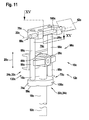
- FIG. 11 is another alternative guide device 10c or a Hubelement arrangementsvoruze 12c for a hand tool, in the form of a jigsaw, as shown in the FIG. 1 shown is shown.
- the guide device 10c has a guide unit 16c for guiding a lifting element 18c in a stroke direction 20c. Furthermore, the guide unit 16c is pivotally mounted about a pendulum axis 22c, which is arranged fixedly relative to a housing 42c of the portable power tool 14c via a pivot pin 160c, and thus forms a pendulum element 58c.
- the pendulum element 58c has a rectangular basic shape and is designed in several parts or has four components 162c on ( FIG. 12 ).
- Two components 162c are each formed by a web 66c, in the form of a cylindrical pin, which extends parallel to the stroke direction 20c.
- These webs 66c are each at an end 68c, which is arranged at the mounted in the jigsaw state of the guide device 10c on the pendulum axis 22c, via a third component 162c, which is perpendicular to the stroke direction 20c and is designed in the form of a connecting web 70c, connected.
- the ends 68c opposite the ends 68c of the webs 66c are connected via the fourth component 162c and a further connecting web 74c.
- the four components 162c include an opening 78c extending in the lift direction 20c and having a 0-shape.
- the webs 66c of the guide unit 16c form guide elements 86c, each having three running surfaces 26c, wherein the running surfaces 26c are offset by approximately 90 ° over a circumference 164c of the cylinder rod (shown in FIG. 15 ).
- the first bearing unit 24c is movable directly on the guide unit 16c during a movement in the lifting direction 20c.
- the guide device 10c has a bearing arrangement 132c with two bearing units 24c, 34c or slide bearing units 32c designed analogously to the first two embodiments.
- the lifting element 18c which is designed as a hollow body 44c
- the first bearing unit 24c as in FIG. 13 is shown, a slide unit 90c with a perpendicular to the stroke direction 20c aligned connecting element 28c and the lifting element 18c itself on.
- the connecting element 28c has analogous to the embodiments of the FIGS. 1 to 10 a coupling element 38c and a receiving element 36c for the lifting element 18b.
- the receiving element 36c is designed as a circular recess 166c, which is adapted to an outer circumference 126c of the lifting element 18c and extends centrally through a longitudinal axis 122c of the guide unit 16c in the connecting element 28c (FIG. FIG. 14 ).
- the connecting element 28c and the lifting element 18c are positively connected in the assembled state of the sliding unit 90c by means of a securing pin 168c, which extends perpendicular to a main extension plane 108c of the guide unit 16c. This locking pin 168c, when mounted from one side facing away from a motor output 40c, is pushed through corresponding openings 170c, 172c in the connecting member 28c and the lifting member 18c ( FIG. 13 ).
- two contact elements 30c corresponding to the guide unit 16c are formed in the connecting element 28c in the form of laterally arranged rectangular recesses 174c which are perpendicular and parallel to the main extension plane 108c in their extensions 106c, 176c to an outer diameter 178c of the webs 66c or the cylindrical pins are adjusted ( FIG. 15 ).
- Areas 180c of the recesses 174c facing the lifting element 18c are spaced so far apart that the webs 66c of the guide unit 16c can be received in the contact elements 30c and the recesses 174c so that the running surfaces 26c of the webs 66c facing the Lifting element 18c have, at the corresponding to these treads 140c, which are formed on the surfaces 180c of the recesses 174c, bear directly. Furthermore, the two further running surfaces 140c lie on opposite inner surfaces 182c the recesses 174c.
- the slide bearing unit 32c of the first bearing unit 24c is thus formed by the raceway surfaces 26c of the guide unit 16c and the raceway surfaces 140c of the first bearing unit 24c and the contact elements 30c, respectively, which minimizes rotation of the slide unit 90c.
Abstract
Description
Es ist bereits eine Führungsvorrichtung, insbesondere eine Hubelementführungsvorrichtung, für eine Handwerkzeugmaschine vorgeschlagen worden, die eine Führungseinheit aufweist, die um eine Pendelachse schwenkbar gelagert ist und zu einer Führung zumindest eines Hubelements in eine Hubrichtung vorgesehen ist.There has already been proposed a guide device, in particular a Hubelementführungsvorrichtung, for a power tool, which has a guide unit which is pivotally mounted about a pendulum axis and is provided for guiding at least one lifting element in a stroke direction.
Es wird eine Führungsvorrichtung, insbesondere eine Hubelementführungsvorrichtung, für eine Handwerkzeugmaschine, mit zumindest einer Führungseinheit zu einer Führung zumindest eines Hubelements in eine Hubrichtung vorgeschlagen, wobei die Führungseinheit um eine Pendelachse schwenkbar gelagert ist und wobei das Hubelement mittels zumindest einer ersten Lagereinheit entlang der Führungseinheit geführt ist. In diesem Zusammenhang soll unter einer "Führungseinheit" insbesondere eine Einheit verstanden werden, die eine Bewegungsrichtung, insbesondere eines Hubelements, während eines Bewegungsvorgangs einer Hubbewegung vorgibt. Alternativ und/oder zusätzlich kann die Führungseinheit dazu vorgesehen sein, eine Bewegung des Hubelements, die von der bevorzugten Bewegungsrichtung bzw. von einer Hubrichtung abweicht, einzuschränken. Die Führungseinheit ist beispielsweise als ein Pendelelement und/oder eine Wippe ausgebildet. Alternativ und/oder zusätzlich kann die Führungseinheit einteilig oder mehrteilig ausgebildet sein, wobei bei einer mehrteiligen Ausführung die Führungseinheit teilweise demontierbar ist. Generell wäre jedoch auch jede andere, dem Fachmann als zweckdienlich erscheinende Ausgestaltung denkbar. Hierfür weist die Führungseinheit bevorzugt ein Führungselement auf, wobei unter einem "Führungselement" insbesondere ein Element, wie beispielsweise ein Steg, eine Stange, eine Begrenzung einer Ausnehmung und/oder jede andere, dem Fachmann als sinnvoll erscheinende Ausgestaltung verstanden werden soll. Alternativ und/oder zusätzlich weist dieses Führungselement eine Ausrichtung auf, die insbesondere parallel zur Hubrichtung ausgerichtet ist, wobei das Führungselement durch diese Ausrichtung die Bewegungsrichtung des Hubelements bestimmt. Ferner soll unter einem "Hubelement" insbesondere ein Element, wie beispielsweise eine Hubstange, verstanden werden, das in zumindest einem Betriebszustand der Handwerkzeugmaschine in einer Auf- und Abwärtsbewegung, insbesondere einer fortlaufenden Auf- und Abwärtsbewegung, bevorzugt von einem Antriebsmittel, wie einem Motor, angetrieben wird. Zudem weist das Hubelement eine Werkzeugaufnahme für ein Werkzeug, wie ein Sägeblatt, auf. Zudem soll unter einer "Pendelachse" insbesondere eine Achse verstanden werden, um die die Führungseinheit insbesondere in einem Arbeitsbetrieb bzw. Schneidebetrieb der Handwerkzeugmaschine schwenkbar ist, wobei unter "schwenkbar" insbesondere eine Drehung um diese Achse in einem Winkelbereich von 180°, bevorzugt von 90° und besonders bevorzugt von 30° verstanden werden soll. Des Weiteren soll unter einer "Lagereinheit" insbesondere eine Einheit verstanden werden, die Lagerkräfte des Hubelements aufnimmt und auf die Führungseinheit und/oder auf ein Gehäuse, wie ein Getriebegehäuse oder ein Außengehäuse der Handwerkzeugmaschine, überträgt. Die Lagereinheit kann einteilig oder mehrteilig ausgebildet sein, wodurch auch die Lagereinheit teilweise demontierbar ist. Unter dem Begriff "geführt" soll hier insbesondere eine passive Beeinflussung bzw. Einschränkung der Bewegungsrichtung des Hubelements verstanden werden.It is a guide device, in particular a Hubelementführungsvorrichtung, proposed for a hand tool, with at least one guide unit to guide at least one lifting element in a stroke direction, wherein the guide unit is pivotally mounted about a pendulum axis and wherein the lifting element guided by at least a first bearing unit along the guide unit is. In this context, a "guide unit" should be understood to mean in particular a unit which specifies a direction of movement, in particular of a lifting element, during a movement process of a lifting movement. Alternatively and / or additionally, the guide unit can be provided to restrict a movement of the lifting element, which differs from the preferred direction of movement or from a stroke direction. The guide unit is designed, for example, as a pendulum element and / or a rocker. Alternatively and / or additionally, the guide unit may be formed in one or more parts, wherein in a multi-part design, the guide unit partially disassembled is. In general, however, any other arrangement that appears appropriate to a person skilled in the art would also be conceivable. For this purpose, the guide unit preferably has a guide element, wherein a "guide element" is to be understood in particular an element, such as a web, a rod, a boundary of a recess and / or any other, the skilled person appear appropriate design. Alternatively and / or additionally, this guide element has an orientation, which is aligned in particular parallel to the stroke direction, wherein the guide element determines the direction of movement of the lifting element by this orientation. Furthermore, a "lifting element" is to be understood as meaning in particular an element, such as a lifting rod, which in at least one operating state of the hand tool machine moves up and down, in particular a continuous upward and downward movement, preferably by a drive means, such as a motor. is driven. In addition, the lifting element has a tool holder for a tool, such as a saw blade. In addition, a "pendulum axis" should be understood to mean, in particular, an axis about which the guide unit can be pivoted, in particular in a working mode or cutting operation of the handheld power tool, with "pivoting" in particular rotation about this axis in an angular range of 180 °, preferably 90 ° ° and particularly preferably 30 ° to be understood. Furthermore, a "bearing unit" should be understood to mean, in particular, a unit which receives bearing forces of the lifting element and transmits them to the guide unit and / or to a housing, such as a gearbox housing or an outer housing of the handheld power tool. The storage unit may be formed in one or more parts, whereby the storage unit is partially disassembled. The term "guided" is to be understood here in particular as a passive influencing or restriction of the direction of movement of the lifting element.
Durch die erfindungsgemäße Ausgestaltung können die Pendelachse und die Lagerung des Hubelements konstruktiv einfach voneinander getrennt werden, was bei fehlender Beeinträchtigung einer Funktion der Führungsvorrichtung zu einer vorteilhaften Reduzierung einer Einbauhöhe der Führungsvorrichtung des Hubelements und des Hubelements selbst führt. Ferner kann dadurch ein Bauraum bzw. ein Getrieberaum vorteilhaft reduziert werden, was sich unmittelbar auf Größe und Gewicht der Handwerkzeugmaschine auswirkt.The inventive design, the pendulum axis and the bearing of the lifting element can be structurally easily separated from each other, resulting in the absence of impairment of a function of the guide device to an advantageous reduction in installation height of the guide device of the lifting element and the lifting element itself. Furthermore, a space or a gear chamber can be advantageously reduced thereby, which has a direct effect on the size and weight of the power tool.
Des Weiteren wird vorgeschlagen, dass die Führungseinheit zumindest eine Lauffläche aufweist. Hierbei soll unter einer "Lauffläche" insbesondere eine Fläche verstanden werden, die in direktem Kontakt mit zumindest der ersten Lagereinheit bzw. einem Bauteil der ersten Lagereinheit und/oder einem Anteil dieses Bauteils steht. Besonders vorteilhaft weist die Führungseinheit zumindest zwei Laufflächen auf. Alternativ und/oder zusätzlich ist die erste Lagereinheit bzw. das Bauteil der ersten Lagereinheit und/oder ein Anteil des Bauteils direkt gleitend auf der Lauffläche bewegbar. Ferner kann die Lauffläche alternativ und/oder zusätzlich dazu vorgesehen sein, die Lagerkräfte der ersten Lagereinheit direkt aufzunehmen. Bevorzugt ist die zumindest eine Lauffläche an dem Führungselement der Führungseinheit angeordnet und vorteilhaft einstückig mit diesem ausgebildet, wobei unter "einstückig" hierbei insbesondere "aus einem Guss gebildet" und/oder "als ein Bauteil ausgebildet" verstanden werden soll. Ferner kann auch mehr als eine Lauffläche vorgesehen sein, wobei ein Fachmann eine Anzahl konstruktionsbedingt selbst auswählen wird. Generell wäre es auch möglich, anstelle eines Flächenkontakts mehrere Linienkontakte vorzusehen. Durch die Realisierung der Lauffläche kann eine Bewegung des Hubelements besonders einfach gestaltet werden. Zudem können eine große Auflagefläche und damit eine gute Kraftverteilung bereitgestellt werden.Furthermore, it is proposed that the guide unit has at least one running surface. In this case, a "running surface" should be understood to mean, in particular, a surface which is in direct contact with at least the first bearing unit or a component of the first bearing unit and / or a portion of this component. Particularly advantageously, the guide unit has at least two running surfaces. Alternatively and / or additionally, the first bearing unit or the component of the first bearing unit and / or a portion of the component is directly slidably movable on the running surface. Furthermore, the tread may alternatively and / or additionally be provided to directly receive the bearing forces of the first bearing unit. Preferably, the at least one running surface is arranged on the guide element of the guide unit and advantageously integrally formed therewith, wherein "integral" here in particular "formed from a cast" and / or "designed as a component" to be understood. Further, more than one tread may be provided, with a person skilled in the art selecting a number by design. In general, it would also be possible to provide several line contacts instead of a surface contact. By realizing the running surface, a movement of the lifting element can be made particularly simple. In addition, a large contact surface and thus a good power distribution can be provided.
Zudem kann es von Vorteil sein, wenn die erste Lagereinheit zumindest ein im Wesentlichen senkrecht zur Hubrichtung ausgerichtetes Verbindungselement aufweist, das zumindest zwei mit der Führungseinheit korrespondierende Kontaktelemente aufweist. In diesem Zusammenhang soll unter der Wendung "im Wesentlichen senkrecht" insbesondere verstanden werden, dass das Verbindungselement mit einer Winkelabweichung von kleiner als plus/minus 15°, bevorzugt kleiner als plus/minus 5° und besonders bevorzugt kleiner als plus/minus 2° bezüglich eines Referenzobjekts, hier einer Senkrechten zur Hubrichtung, ausgerichtet ist. Unter einem "Kontaktelement" soll hier insbesondere ein Element verstanden werden, das zumindest eine Lauffläche aufweist, die mit der Lauffläche der Führungseinheit bzw. des Führungselements direkt korrespondiert. Diese Lauffläche kann beispielsweise einstückig mit einem Steg und/oder einer Begrenzung einer Ausnehmung und/oder jeder anderen, dem Fachmann als sinnvoll erscheinenden Ausgestaltung der Lagereinheit bzw. dem Bauteil der ersten Lagereinheit ausgebildet sein. Ein "Verbindungselement" stellt hier insbesondere ein Element dar, das mittels der zwei Kontaktelemente in direktem Kontakt zu zumindest zwei Bereichen bzw. Führungselementen der Führungseinheit steht. Alternativ und/oder zusätzlich verbindet das Verbindungselement zumindest zwei Bereiche der Führungseinheit über die Kontaktelemente direkt miteinander, also ohne ein weiteres zwischengeschaltetes Bauelement. Hierbei weisen die zwei Bereiche der Führungseinheit insbesondere jeweils eine Lauffläche auf und/oder erstrecken sich bevorzugt im Wesentlichen parallel zur Hubrichtung. Das Verbindungselement und das Kontaktelement sind bevorzugt einstückig miteinander ausgeführt, wobei "einstückig" hierbei insbesondere bedeutet, dass das Verbindungselement nur unter Funktionsverlust der Verbindung der beiden Bereiche der Führungseinheit von dem Kontaktelement getrennt werden kann. Durch das Verbindungselement bzw. eine Interaktion der beiden Koppelelemente mit zwei Bereichen der Führungseinheit kann eine Verdrehung des Hubelements relativ zu der Führungseinheit sicher und konstruktiv einfach reduziert und/oder verhindert werden, was sich unmittelbar auf ein gutes Sägeergebnis auswirkt.In addition, it may be advantageous if the first bearing unit has at least one connecting element which is oriented substantially perpendicular to the stroke direction and has at least two contact elements corresponding to the guide unit. In this context, the term "substantially perpendicular" is to be understood in particular to mean that the connecting element with an angular deviation of less than plus / minus 15 °, preferably less than plus / minus 5 ° and particularly preferably less than plus / minus 2 ° a reference object, here a perpendicular to the stroke direction, is aligned. A "contact element" is to be understood here in particular as an element which has at least one running surface which directly corresponds to the running surface of the guide unit or of the guide element. This tread can, for example, in one piece with a web and / or a boundary of a recess and / or each other, the skilled person appear appropriate design of the bearing unit or the component of the first bearing unit. A "connecting element" here represents in particular an element which is in direct contact with at least two regions or guide elements of the guide unit by means of the two contact elements. Alternatively and / or additionally, the connecting element connects at least two regions of the guide unit directly to each other via the contact elements, ie without a further intermediate component. In this case, the two regions of the guide unit in particular each have a running surface and / or preferably extend substantially parallel to the stroke direction. The connecting element and the contact element are preferably embodied integrally with one another, wherein "integral" here means in particular that the connecting element can only be separated from the contact element with loss of function of the connection of the two regions of the guide unit. By means of the connecting element or an interaction of the two coupling elements with two regions of the guide unit, a rotation of the lifting element relative to the guide unit can be safely and structurally simply reduced and / or prevented, which has a direct effect on a good sawing result.
Vorteilhafterweise ist die erste Lagereinheit als eine Gleitlagereinheit ausgebildet. Hierbei soll unter einer "Gleitlagereinheit" insbesondere eine Einheit verstanden werden, bei der Interaktionspartner direkt und/oder nur durch eine Schmiermittelschicht getrennt aneinander vorbei bewegbar sind und/oder deren relative Bewegung zueinander auf einer Gleitreibung beruht. Die Gleitlagereinheit wird bevorzugt von der Lauffläche/den Laufflächen der Führungseinheit und der Lauffläche/den Laufflächen der Lagereinheit bzw. der Kontaktelemente gebildet. Die erste Lagereinheit ist bevorzugt an einem oberen Ende des Hubelements, das von einer Werkzeugaufnahme wegweist, angeordnet. Durch die Ausführung der Lagereinheit als Gleitlagereinheit kann die Lagereinheit konstruktiv einfach gestaltet werden und sie kann kostengünstig sowie Bauraum und Bauteil sparend realisiert werden.Advantageously, the first bearing unit is designed as a sliding bearing unit. In this case, a "sliding bearing unit" is to be understood as meaning in particular a unit in which interaction partners are moved past one another directly and / or only past a lubricant layer and / or their relative movement relative to one another is based on sliding friction. The sliding bearing unit is preferably formed by the running surface / the running surfaces of the guide unit and the running surface / the running surfaces of the bearing unit or the contact elements. The first bearing unit is preferably arranged at an upper end of the lifting element, which points away from a tool holder. Due to the design of the bearing unit as a sliding bearing unit, the bearing unit can be structurally simple and they can be realized cost-effective and space and component saving.
Ferner ist es vorteilhaft, wenn die Führungsvorrichtung eine weitere Lagereinheit aufweist, die als eine Gleitlagereinheit ausgebildet ist. Diese Gleitlagereinheit ist insbesondere als Linearlager ausgebildet und weist bevorzugt eine Sinterbuchse auf. Alternativ und/oder zusätzlich wäre eine Ausgestaltung als Schub- und/oder Drehschubgelenk denkbar. Grundsätzlich wäre jedoch jede andere, dem Fachmann als zweckdienlich erscheinende Ausgestaltung der Gleitlagereinheit, insbesondere beruhend auf einem selbstschmierenden Prinzip, denkbar. Mittels der weiteren Lagereinheit bzw. Gleitlagereinheit kann das Hubelement vorteilhaft gelagert und gleichzeitig linear geführt werden.Furthermore, it is advantageous if the guide device has a further bearing unit, which is designed as a sliding bearing unit. This slide bearing unit is designed in particular as a linear bearing and preferably has a sintered bushing. Alternatively and / or additionally would be an embodiment as a thrust and / or rotary push joint conceivable. In principle, however, any other embodiment of the sliding bearing unit which appears to the person skilled in the art to be suitable, in particular based on a self-lubricating principle, would be conceivable. By means of the further bearing unit or plain bearing unit, the lifting element can be advantageously stored and simultaneously guided linear.
Des Weiteren kann es vorteilhaft sein, wenn die weitere Lagereinheit ortsfest an der Führungseinheit angeordnet ist. In diesem Zusammenhang definiert der Begriff "ortsfest", dass die weitere Lagereinheit relativ zu der Führungseinheit unbeweglich bzw. an dieser fixiert ist. Alternativ und/oder zusätzlich bedeutet "ortsfest" hier, dass die weitere Lagereinheit bei einer Bewegung, wie einer Pendelbewegung der Führungseinheit, mit dieser, insbesondere um die Pendelachse, bewegt wird. Durch die Realisierung der festen Anordnung der weiteren Lagereinheit kann eine Lageranordnung mit der ersten Lagereinheit und der weiteren Lagereinheit konstruktiv einfach und Bauraum sparend ausgeführt werden.Furthermore, it may be advantageous if the further storage unit is arranged stationarily on the guide unit. In this context, the term "stationary" defines that the further bearing unit is immovable or fixed relative to the guide unit. Alternatively and / or additionally, "stationary" here means that the further bearing unit is moved during a movement, such as a pendulum movement of the guide unit, with it, in particular around the pendulum axis. By realizing the fixed arrangement of the further storage unit, a bearing arrangement with the first storage unit and the further storage unit structurally simple and space-saving can be performed.
In einer weiteren Ausgestaltung der Erfindung wird vorgeschlagen, dass die erste Lagereinheit ein Aufnahmeelement für das Hubelement aufweist. In diesem Zusammenhang soll unter einem "Aufnahmeelement" insbesondere ein Element und/oder eine Ausgestaltung verstanden werden, das bzw. die in direktem Kontakt zu dem Hubelement steht. Alternativ und/oder zusätzlich soll darunter verstanden werden, dass das Element bzw. die Ausgestaltung in seiner bzw. ihrer Kontur an eine Außenkontur des Hubelements angepasst ist, so dass das Element bzw. die Ausgestaltung an zumindest 10 % einer Außenkontur und/oder eines Umfangs des Hubelements angeordnet bzw. angepasst ist. Das Aufnahmeelement ist beispielsweise als U-förmige und/oder als napfförmige Einbuchtung und/oder als Ausnehmung mit einem das Hubelement umgreifenden Profil ausgestaltet. Grundsätzlich wäre jedoch jede andere, dem Fachmann als sinnvoll erscheinende Formgebung denkbar. Das Aufnahmeelement und das Hubelement sind bevorzugt stoffschlüssig, formschlüssig und/oder kraftschlüssig miteinander verbunden. Hierbei kommt jede, dem Fachmann als gebräuchlich erscheinende Art der Herstellung eines Stoff-, Form- und/oder Kraftschlusses, wie etwa Kleben, Sintern, Schweißen, Schrauben, Nieten etc., in Betracht. Durch den Stoff-, Form- und/oder Kraftschluss sind das Hubelement und die erste Lagereinheit konstruktiv einfach, zuverlässig und Bauteil sparend zusammen in Hubrichtung bewegbar angeordnet.In a further embodiment of the invention, it is proposed that the first bearing unit has a receiving element for the lifting element. In this context, a "receiving element" should be understood to mean, in particular, an element and / or a design which is in direct contact with the lifting element. Alternatively and / or additionally should be understood that the element or the design is adapted in its or its contour to an outer contour of the lifting element, so that the element or the configuration of at least 10% of an outer contour and / or a circumference the lifting element is arranged or adapted. The receiving element is configured, for example, as a U-shaped and / or cup-shaped indentation and / or as a recess with a profile encompassing the lifting element. In principle, however, any other shape that appears appropriate to the person skilled in the art would be conceivable. The receiving element and the lifting element are preferably cohesively, positively and / or non-positively connected to each other. In this context, any type of fabric, form and / or adhesion connection that appears to the person skilled in the art, such as gluing, sintering, welding, screwing, riveting, etc., comes into consideration. By the fabric, form and / or adhesion are the Lifting element and the first storage unit structurally simple, reliable and component-saving movably arranged together in the stroke direction.
Ferner wird vorgeschlagen, dass die erste Lagereinheit ein Koppelelement aufweist, das dazu vorgesehen ist, mit einem Motorabtrieb der Handwerkzeugmaschine gekoppelt zu werden. Hierbei soll unter einem "Koppelelement" insbesondere ein Element verstanden werden, das die erste Lagereinheit und einen Motorabtrieb, wie beispielsweise eine Ankerwelle, mit einem nachgeschalteten Getriebe bzw. Pendelgetriebe wirkungsmäßig verbindet. Ferner soll unter "vorgesehen" speziell ausgestattet und/oder ausgelegt verstanden werden. Durch das Koppelelement kann ein Antrieb eines Motors konstruktiv einfach und sicher auf das mit der ersten Lagereinheit verbundene Hubelement übertragen werden.It is also proposed that the first bearing unit has a coupling element, which is intended to be coupled to a motor output of the power tool. This is to be understood by a "coupling element" in particular an element that connects the first bearing unit and a motor output, such as an armature shaft, operatively connected to a downstream transmission or pendulum. Furthermore, should be understood to be "equipped" specially equipped and / or designed. By means of the coupling element, a drive of a motor can be transferred in a structurally simple and reliable manner to the lifting element connected to the first bearing unit.
Eine konstruktiv einfache und Bauteil sparende Befestigung der Führungsvorrichtung und damit des Hubelements kann vorteilhaft erreicht werden, wenn die Führungsvorrichtung ein Lagermittel aufweist, das dazu vorgesehen ist, die Führungseinheit an einem Gehäuse der Handwerkzeugmaschine zu lagern. Hierbei soll unter einem "Lagermittel" ein Mittel verstanden werden, das dazu vorgesehen ist, Lagerkräfte der Führungseinheit aufzunehmen und/oder an das Gehäuse der Handwerkzeugmaschine weiterzuleiten. Zudem soll unter dem "Gehäuse" insbesondere ein Außengehäuse der Handwerkzeugmaschine verstanden werden. Generell wäre jedoch auch eine Befestigung an einem anderen in der Handwerkzeugmaschine angeordneten Gehäuse, wie etwa einem Getriebe- und/oder Motorgehäuse, möglich.A structurally simple and component-saving attachment of the guide device and thus of the lifting element can be advantageously achieved if the guide device has a bearing means which is intended to support the guide unit to a housing of the power tool. In this case, a "bearing means" is to be understood as a means which is intended to receive bearing forces of the guide unit and / or to forward it to the housing of the handheld power tool. In addition, should be understood by the "housing" in particular an outer housing of the power tool. In general, however, an attachment to another arranged in the power tool housing, such as a gear and / or motor housing, would be possible.
Zudem wird vorgeschlagen, dass die Pendelachse relativ zu einem Gehäuse der Handwerkzeugmaschine ortsfest angeordnet ist. In diesem Zusammenhang soll unter "ortsfest" insbesondere verstanden werden, dass die Pendelachse relativ zu dem Gehäuse fixiert bzw. unbeweglich und insbesondere axial unbeweglich und/oder undrehbar ist. Durch die ortsfeste Anordnung kann eine bei herkömmlichen Handwerkzeugmaschinen gebräuchliche Pendelbewegung ohne konstruktive Umgestaltung beibehalten werden, wodurch vorteilhaft ein bewährtes Funktionsprinzip Verwendung findet.In addition, it is proposed that the pendulum axis is arranged stationary relative to a housing of the power tool. In this context, the term "stationary" is understood in particular to mean that the pendulum axis is fixed relative to the housing or immovable and in particular axially immovable and / or non-rotatable. Due to the stationary arrangement, a conventional hand-held power tool pendulum motion can be maintained without structural redesign, which advantageously finds a proven functional principle use.
Eine bevorzugte Weiterbildung besteht darin, dass das Hubelement als Hohlkörper ausgebildet ist. In diesem Zusammenhang soll unter einem "Hohlkörper" insbesondere ein Körper verstanden werden, der eine Mantelfläche aufweist, die einen Hohlraum umgibt bzw. einschließt. Hierbei kann eine Außenkontur des Hohlkörpers bzw. des Hubelements jede erdenkliche Form, wie beispielsweise vieleckig, quadratisch, oval oder rund, aufweisen. Durch die erfindungsgemäße Ausgestaltung können ein geringes Hubgewicht und somit eine geringe Ausgleichsmasse bereitgestellt werden, was sich unmittelbar vorteilhaft auf ein geringes Gesamtgewicht des Hubelements auswirkt. Ferner kann so konstruktiv einfach ein Kosten sparendes und leichtes Hubelement bereitgestellt werden.A preferred development is that the lifting element is designed as a hollow body. In this context, a "hollow body" should be understood to mean in particular a body which has a lateral surface which surrounds or encloses a cavity. In this case, an outer contour of the hollow body or of the lifting element of any conceivable shape, such as polygonal, square, oval or round, have. Due to the configuration of the invention, a low lifting weight and thus a low leveling compound can be provided, which has an immediate effect on a low total weight of the lifting element. Furthermore, so structurally simple, a cost-saving and lightweight lifting element can be provided.
Eine weitere Ausgestaltung der Erfindung sieht eine Handwerkzeugmaschine, insbesondere eine Stichsäge, mit zumindest einer Führungsvorrichtung vor. Generell wäre jedoch ein Einsatz der Führungsvorrichtung in jeder anderen, dem Fachmann als denkbar erscheinenden Handwerkzeugmaschine, insbesondere mit einem Pendelantrieb eines Hubelements, denkbar.A further embodiment of the invention provides a hand tool, in particular a jigsaw, with at least one guide device. In general, however, would be an application of the guide device in any other, the skilled worker as conceivable hand tool, especially with a pendulum drive a lifting element, conceivable.
Weitere Vorteile ergeben sich aus der folgenden Zeichnungsbeschreibung. In der Zeichnung sind Ausführungsbeispiele der Erfindung dargestellt. Die Zeichnung, die Beschreibung und die Ansprüche enthalten zahlreiche Merkmale in Kombination. Der Fachmann wird die Merkmale zweckmäßigerweise auch einzeln betrachten und zu sinnvollen weiteren Kombinationen zusammenfassen.Further advantages emerge from the following description of the drawing. In the drawings, embodiments of the invention are shown. The drawing, the description and the claims contain numerous features in combination. The person skilled in the art will expediently also consider the features individually and combine them into meaningful further combinations.
Es zeigen:
- Fig. 1
- eine Handwerkzeugmaschine mit einer erfindungsgemäßen Füh- rungsvorrichtung,
- Fig. 2
- die Führungsvorrichtung der
Figur 1 in einer Seitenansicht, - Fig. 3
- eine Gleiteinheit der Führungsvorrichtung der
Figur 2 in einer De- taildarstellung, - Fig. 4
- die Führungsvorrichtung der
Figur 1 bei einer Montage der Gleitein- heit derFigur 3 , - Fig. 5
- ein Teil einer ersten Lagereinheit schematisch als Schnitt entlang der Linie V-V der
Figur 4 , - Fig. 6
- eine alternative Führungsvorrichtung von vorne,
- Fig. 7
- eine Gleiteinheit der Führungsvorrichtung der
Figur 6 in einer De- taildarstellung, - Fig. 8
- ein Aufnahmebauteil der Gleiteinheit der
Figur 7 , - Fig. 9
- ein Teil einer ersten Lagereinheit schematisch als Schnitt entlang der Linie IX-IX der
Figur 6 , - Fig. 10 a-e
- verschiedene Anordnungsmöglichkeiten eines Führungselements der Führungsvorrichtung der
Figur 6 und der Gleiteinheit derFigur 7 relativ zueinander, - Fig. 11
- eine weitere alternative Führungsvorrichtung von vorne,
- Fig. 12
- die Führungsvorrichtung der
Figur 11 vor einer Montage, - Fig. 13
- eine Gleiteinheit der Führungsvorrichtung der
Figur 11 bei einer Montage eines Hubelements, - Fig. 14
- ein Verbindungselement der Gleiteinheit der
Figur 13 und - Fig. 15
- ein Teil einer ersten Lagereinheit schematisch als Schnitt entlang der Linie XV-XV der
Figur 11 .
- Fig. 1
- a hand tool with a guide device according to the invention,
- Fig. 2
- the guiding device of
FIG. 1 in a side view, - Fig. 3
- a sliding unit of the guide device of
FIG. 2 in a portrait view, - Fig. 4
- the guiding device of
FIG. 1 during assembly of the sliding unit of theFIG. 3 . - Fig. 5
- a part of a first storage unit schematically as a section along the line VV of
FIG. 4 . - Fig. 6
- an alternative guiding device from the front,
- Fig. 7
- a sliding unit of the guide device of
FIG. 6 in a portrait view, - Fig. 8
- a receiving member of the sliding unit of
FIG. 7 . - Fig. 9
- a part of a first storage unit schematically as a section along the line IX-IX of
FIG. 6 . - Fig. 10 ae
- various possible arrangements of a guide element of the guide device of
FIG. 6 and the sliding unit ofFIG. 7 relative to each other, - Fig. 11
- another alternative guiding device from the front,
- Fig. 12
- the guiding device of
FIG. 11 before a montage, - Fig. 13
- a sliding unit of the guide device of
FIG. 11 during a mounting of a lifting element, - Fig. 14
- a connecting element of the sliding unit of
FIG. 13 and - Fig. 15
- a part of a first storage unit schematically as a section along the line XV-XV of
FIG. 11 ,
Die Handwerkzeugmaschine 14a weist ferner eine Führungsvorrichtung 10a in der Form einer Hubelementführungsvorrichtung 12a auf, mit einer Führungseinheit 16a zu einer Führung des Hubelements 18a in Hubrichtung 20a.The
Wie in der
Das Pendelelement 58a weist eine rechteckige Grundform und vier sich parallel zur Hubrichtung 20a erstreckende Stege 66a auf. Die Stege 66a sind jeweils an einem Ende 68a, das bei dem in die Stichsäge 46a eingebauten Zustand der Führungsvorrichtung 10a an der Pendelachse 22a angeordnet ist, über einen Verbindungssteg 70a, der senkrecht zur Hubrichtung 20a verläuft, verbunden. Den Enden 68a gegenüberliegende Enden 72a der Stege 66a sind über einen weiteren Verbindungssteg 74a verbunden. Die Verbindungsstege 70a, 74a und die beiden äußeren Stege 66a bilden somit die rechteckiger Grundform. Die Stege 66a sind senkrecht zur Hubrichtung 20a durch sich in Hubrichtung 20a erstreckende Öffnungen 76a, 78a, 80a beabstandet, wobei die beiden äußeren Öffnungen 76a, 80a eine gleiche Breite 82a aufweisen. Die mittlere Öffnung 78a hingegen weist eine Breite 84a auf, die ca. um das Dreifache größer ist als die Breite der Öffnungen 76a, 80a. Generell wäre hier jedoch jedes, dem Fachmann als zweckdienlich erscheinende Breitenverhältnis denkbar.The
Die Führungseinheit 16a weist zudem vier Führungselemente 86a auf, die von den Stegen 66a gebildet sind. Die Führungsfunktion der Führungselemente 86a wird von Begrenzungen 88a der äußeren Öffnungen 76a, 80a übernommen, die sich in paralleler Richtung zu der Hubrichtung 20a erstrecken. Das Hubelement 18a ist mittels einer ersten Lagereinheit 24a entlang der Führungseinheit 16a geführt. Zu dieser Führung weist die Führungseinheit 16a vier Laufflächen 26a bzw. weist jedes Führungselement 86a eine Lauffläche 26a auf, über die die Führungseinheit 16a in direktem Kontakt mit der ersten Lagereinheit 24a steht. Ferner ist die erste Lagereinheit 24a während einer Bewegung in Hubrichtung 20a direkt auf den Laufflächen 26a gleitend bewegbar. Die Laufflächen 26a erstrecken sich jeweils entlang den Begrenzungen 88a der äußeren Öffnungen 76a, 80a. Jeweils zwei Laufflächen 26a sind an zwei Begrenzungen 88a der Öffnungen 76a, 80a angeordnet, die sich gegenüberliegen.The
Zu dieser Führung weist die erste Lagereinheit 24a eine Gleiteinheit 90a auf, die mit einem senkrecht zur Hubrichtung 20a ausgerichteten Verbindungselement 28a ausgestattet ist. Die Gleiteinheit 90a trägt zwei mit der Führungseinheit 16a bzw. mit den Laufflächen 26a korrespondierende Kontaktelemente 30a. Das Verbindungselement 28a dient zu einer Überbrückung eines Abstands 92a von äußeren Rändern der Öffnungen 76a, 80a zueinander und erstreckt sich somit über eine gesamte Breite 94a der Führungseinheit 16a, wobei sich die Breite 94a senkrecht zur Hubrichtung 20a erstreckt. Eine Länge 96a des Verbindungselements 28a in Hubrichtung 20a ist vom Fachmann so gewählt, dass eine gute Befestigung des Hubelements 18a und eine erforderliche Stabilität der Gleiteinheit 90a gewährleistet werden. Ferner ist die Gleiteinheit 90a bzw. das Verbindungselement 28a bei dem in die Stichsäge 46a eingebauten Zustand der Führungsvorrichtung 10a auf einer Seite 98a der Führungseinheit 16a angeordnet, die zu einem Motorabtrieb 40a weist (
Die Kontaktelemente 30a sind, wie dies in
Durch diesen bündigen Abschluss kann, wie dies in
Ferner weist die erste Lagereinheit 24a bzw. das Verbindungselement 28a an der Seite 114a, die von dem Koppelelement 38a wegweist, und auf einer Höhe einer Längsachse 122a des Pendelelements 58a ein sich in Hubrichtung 20a erstreckendes Aufnahmeelement 36a für das Hubelement 18a auf. Das Aufnahmeelement 36a ist als U-förmige Einbuchtung 124a ausgebildet und ist dadurch an einen Teil eines Außenumfangs 126a des Hubelements 18a angepasst. Das Aufnahmeelement 36a und das Hubelement 18a sind mittels eines Schweißens und somit stoffschlüssig miteinander verbunden, wodurch das Verbindungselement 28a und das Hubelement 18a als Gleiteinheit 90a zusammen beweglich angeordnet sind.Furthermore, the
Das Hubelement 18a ist als ein Hohlkörper 44a bzw. als ein Zylindermantel 128a, der einen Hohlraum 130a umschließt, ausgebildet und verläuft in einem montierten Zustand entlang der Öffnung 78a. Ferner ist das Hubelement 18a über eine Lageranordnung 132a in Hubrichtung 20a beweglich gelagert. Die Lageranordnung 132a weist die erste Lagereinheit 24a, die als eine Gleitlagereinheit 32a ausgebildet ist, und eine weitere Lagereinheit 34a, die ebenso als eine Gleitlagereinheit 32a ausgebildet ist, auf. Die erste Lagereinheit 24a ist an einer der Werkzeugaufnahme 52a gegenüberliegenden Seite 134a des Hubelements 18a bzw. an einer zu der Pendelachse 22a weisenden Seite 136a der Führungseinheit 16a angeordnet. Die weitere Lagereinheit 34a ist ortsfest an der Führungseinheit 16a angeordnet, und zwar in dem weiteren Verbindungssteg 74a. Die weitere Lagereinheit 34a ist als eine Sinterbuchse 138a ausgeführt, wodurch die Gleiteinheit 90a bzw. das Hubelement 18a und das Verbindungselement 28a mit dem Kontaktelement 30a linear geführt sind.The lifting
In der
In den
Die
Das Pendelelement 58b hat eine rechteckige Grundform und weist zwei Stege 66b auf, die sich parallel zur Hubrichtung 20b erstrecken. Die Stege 66b sind an einem Ende 68b, das bei dem in die Stichsäge eingebauten Zustand der Führungsvorrichtung 10b an der Pendelachse 22b angeordnet ist, über einen Verbindungssteg 70b verbunden, der senkrecht zur Hubrichtung 20b verläuft. Die den Enden 68b gegenüberliegenden Enden 72b der Stege 66b sind über einen weiteren Verbindungssteg 74b verbunden. Ferner sind die Stege 66b senkrecht zur Hubrichtung 20b durch eine Öffnung 78b, die sich in Hubrichtung 20b erstreckt, beabstandet. Die Stege 66b der Führungseinheit 16b bilden Führungselemente 86b, die jeweils eine Lauffläche 26b aufweisen, wobei die Laufflächen 26b zueinander weisend angeordnet sind. Mittels der Laufflächen 26b ist die erste Lagereinheit 24b während einer Bewegung in Hubrichtung 20b direkt gleitend auf der Führungseinheit 16b bewegbar.The
Die Führungsvorrichtung 10b weist eine Lageranordnung 132b zu einer in Hubrichtung 20b beweglichen Lagerung des Hubelements 18b mit einer ersten Lagereinheit 24b und einer weiteren Lagereinheit 34b auf. Beide Lagereinheiten 24b, 34b sind jeweils als eine Gleitlagereinheit 32b ausgebildet. Zudem ist die weitere Lagereinheit 34b in der Form einer Sinterbuchse (nicht im Detail gezeigt) ausgeführt und ortsfest an der Führungseinheit 16b bzw. in dem weiteren Verbindungssteg 74b angeordnet.The
Die erste Lagereinheit 24b ist an einer Seite 134b des Hubelements 18b angeordnet, die einer Werkzeugaufnahme 52b gegenüberliegt, bzw. an einer Seite 136b der Führungseinheit 16b, die zu der Pendelachse 22b weist. Das Hubelement 18b ist mittels der ersten Lagereinheit 24b entlang der Führungseinheit 16b geführt.The
Hierzu weist die erste Lagereinheit 24b, wie in
Wie in den
Hierbei sind die Kontaktstege 102b senkrecht zur Hubrichtung 20b im eingebauten Zustand so weit voneinander beabstandet, dass ein Abstand 92b der Außenflächen 152b der Kontaktstege 102b, die von dem Hubelement 18b wegweisen, auf eine Breite 84b der Öffnung 78b, die sich senkrecht zur Hubrichtung 20b erstreckt, angepasst ist. Dadurch können die Kontaktelemente 30b bzw. die Kontaktstege 102b in die Öffnung 78b eingreifen. Ferner liegen dadurch Laufflächen 140b der Kontaktstege 102b, die an den Außenflächen 152b der Kontaktstege 102b ausgebildet sind und zu den Laufflächen 26b der Führungseinheit 16b korrespondieren, direkt an den Laufflächen 26a der Führungselemente 86b an (
In der
In
In
In der
Das Pendelelement 58c hat eine rechteckige Grundform und ist mehrteilig ausgeführt bzw. weist vier Bauteile 162c auf (
Ferner weist die Führungsvorrichtung 10c eine Lageranordnung 132c mit zwei analog zu den ersten beiden Ausführungsbeispielen ausgebildeten Lagereinheiten 24c, 34c bzw. Gleitlagereinheiten 32c auf. Zu einer Führung des als ein Hohlkörper 44c ausgeführten Hubelements 18c mittels der ersten Lagereinheit 24c entlang der Führungseinheit 16c weist die erste Lagereinheit 24c, wie in
Das Verbindungselement 28c weist analog zu den Ausführungsbeispielen der
Ferner sind in dem Verbindungselement 28c zwei mit der Führungseinheit 16c korrespondierende Kontaktelemente 30c in der Form von seitlich angeordneten rechteckigen Ausnehmungen 174c ausgebildet, die in ihren Erstreckungen 106c, 176c senkrecht und parallel zu der Haupterstreckungsebene 108c an einen Außendurchmesser 178c der Stege 66c bzw. der Zylinderstifte angepasst sind (
Claims (11)
Applications Claiming Priority (1)
| Application Number | Priority Date | Filing Date | Title |
|---|---|---|---|
| DE102009045035A DE102009045035A1 (en) | 2009-09-25 | 2009-09-25 | Guide device, in particular Hubelementführungsvorrichtung |
Publications (2)
| Publication Number | Publication Date |
|---|---|
| EP2301723A1 true EP2301723A1 (en) | 2011-03-30 |
| EP2301723B1 EP2301723B1 (en) | 2017-07-26 |
Family
ID=43385648
Family Applications (1)
| Application Number | Title | Priority Date | Filing Date |
|---|---|---|---|
| EP10170997.0A Active EP2301723B1 (en) | 2009-09-25 | 2010-07-28 | Guide device, in particular guide device for a lifting element |
Country Status (3)
| Country | Link |
|---|---|
| EP (1) | EP2301723B1 (en) |
| DE (1) | DE102009045035A1 (en) |
| RU (1) | RU2555284C2 (en) |
Citations (8)
| Publication number | Priority date | Publication date | Assignee | Title |
|---|---|---|---|---|
| GB620520A (en) * | 1946-11-07 | 1949-03-25 | Arthur Phillips Dooley | A drilling pillar attachment for electric hand drills, grinders and the like |
| DE907236C (en) * | 1951-06-09 | 1954-03-22 | Siemens Ag | Stand for portable hand drill |
| US2849900A (en) * | 1954-11-02 | 1958-09-02 | Jr Martin C Heidtman | Portable frame for power hand drills |
| GB841780A (en) * | 1957-10-01 | 1960-07-20 | Wilmot Kenneth | Improvements in drilling machines |
| DE2847115A1 (en) * | 1978-10-30 | 1980-05-08 | Carl Zenses | Stand for portable power tool - has bracket sliding on column whose inclination is adjustable using lockable universal joint |
| DE3102555A1 (en) * | 1981-01-27 | 1982-08-26 | Helmut 5277 Marienheide Schwirten | Mounting arrangement for a portable drill |
| EP0144490A2 (en) * | 1983-12-02 | 1985-06-19 | Robert Wolff | Drill or miller guiding device for exchangeable driving machines |
| DE4218982A1 (en) * | 1992-01-08 | 1993-07-15 | Miederhoff Franz Fa | Device for drilling holes in vertical surfaces, e.g side panels in truck - has rectangular frame with rollers supported on panel's upper edge and drill in sliding mount on horizontal cross-piece. |
Family Cites Families (3)
| Publication number | Priority date | Publication date | Assignee | Title |
|---|---|---|---|---|
| SU466078A1 (en) * | 1973-07-26 | 1975-04-05 | Предприятие П/Я Г-4086 | Device for guiding and pressing band saw blade |
| SU1703297A1 (en) * | 1990-02-23 | 1992-01-07 | Головное Специальное Производственное Конструкторско-Технологическое Бюро По Рациональному Применению Режущего Инструмента | Universal tool mandrel |
| DE102008016207B3 (en) * | 2008-03-28 | 2009-07-09 | Metabowerke Gmbh | Motor-driven hand-held jigsaw |
-
2009
- 2009-09-25 DE DE102009045035A patent/DE102009045035A1/en not_active Withdrawn
-
2010
- 2010-07-28 EP EP10170997.0A patent/EP2301723B1/en active Active
- 2010-09-24 RU RU2010139282/02A patent/RU2555284C2/en not_active IP Right Cessation
Patent Citations (8)
| Publication number | Priority date | Publication date | Assignee | Title |
|---|---|---|---|---|
| GB620520A (en) * | 1946-11-07 | 1949-03-25 | Arthur Phillips Dooley | A drilling pillar attachment for electric hand drills, grinders and the like |
| DE907236C (en) * | 1951-06-09 | 1954-03-22 | Siemens Ag | Stand for portable hand drill |
| US2849900A (en) * | 1954-11-02 | 1958-09-02 | Jr Martin C Heidtman | Portable frame for power hand drills |
| GB841780A (en) * | 1957-10-01 | 1960-07-20 | Wilmot Kenneth | Improvements in drilling machines |
| DE2847115A1 (en) * | 1978-10-30 | 1980-05-08 | Carl Zenses | Stand for portable power tool - has bracket sliding on column whose inclination is adjustable using lockable universal joint |
| DE3102555A1 (en) * | 1981-01-27 | 1982-08-26 | Helmut 5277 Marienheide Schwirten | Mounting arrangement for a portable drill |
| EP0144490A2 (en) * | 1983-12-02 | 1985-06-19 | Robert Wolff | Drill or miller guiding device for exchangeable driving machines |
| DE4218982A1 (en) * | 1992-01-08 | 1993-07-15 | Miederhoff Franz Fa | Device for drilling holes in vertical surfaces, e.g side panels in truck - has rectangular frame with rollers supported on panel's upper edge and drill in sliding mount on horizontal cross-piece. |
Also Published As
| Publication number | Publication date |
|---|---|
| RU2555284C2 (en) | 2015-07-10 |
| EP2301723B1 (en) | 2017-07-26 |
| DE102009045035A1 (en) | 2011-03-31 |
| RU2010139282A (en) | 2012-03-27 |
Similar Documents
| Publication | Publication Date | Title |
|---|---|---|
| EP0267973B1 (en) | Power driven saw, in particular electrically powered saw | |
| DE4108982B4 (en) | Swash plate drive | |
| DE102013204372B4 (en) | Hubsägeblatt for a machine tool | |
| EP0267311A1 (en) | Saw blade for a saw with two saw blades arranged side by side, parallel to each other and oppositely reciprocable | |
| EP2836328B1 (en) | Power tool clamping device | |
| WO2010020458A1 (en) | Tool | |
| WO2012156120A1 (en) | Tool holder | |
| DE69936127T2 (en) | saw blade clamp | |
| EP2680995B1 (en) | Portable machine tool | |
| EP2532462A1 (en) | Motorised hand-held saw | |
| DE102012215460A1 (en) | Cutting strand segment | |
| EP2625001B1 (en) | Oscillating hand-held power tool | |
| DE102005063016A1 (en) | Hand tool with Drehgriffverstelleinrichtung | |
| EP2301723B1 (en) | Guide device, in particular guide device for a lifting element | |
| EP0609791B1 (en) | Motor saw with guide bar | |
| EP0267312B1 (en) | Power driven saw, in particular electrically powered saw | |
| EP2029304B1 (en) | Jigsaw machine with saw blade and guide device | |
| DE102011005016A1 (en) | Machine tool separating device | |
| WO2012116826A1 (en) | Machine tool system | |
| DE102011005007A1 (en) | Machine tool separating device | |
| EP2714346A1 (en) | Separation tool | |
| WO2012116831A1 (en) | Portable power tool | |
| WO2012116837A1 (en) | Portable power tool | |
| EP0267313B1 (en) | Guide bar for a saw having two saw blades sliding in opposite direction to each other | |
| DE102020216561A1 (en) | Power transmission device for a machine tool and machine tool with the power transmission device |
Legal Events
| Date | Code | Title | Description |
|---|---|---|---|
| PUAI | Public reference made under article 153(3) epc to a published international application that has entered the european phase |
Free format text: ORIGINAL CODE: 0009012 |
|
| AK | Designated contracting states |
Kind code of ref document: A1 Designated state(s): AL AT BE BG CH CY CZ DE DK EE ES FI FR GB GR HR HU IE IS IT LI LT LU LV MC MK MT NL NO PL PT RO SE SI SK SM TR |
|
| AX | Request for extension of the european patent |
Extension state: BA ME RS |
|
| 17P | Request for examination filed |
Effective date: 20110930 |
|
| REG | Reference to a national code |
Ref country code: DE Ref legal event code: R079 Ref document number: 502010013905 Country of ref document: DE Free format text: PREVIOUS MAIN CLASS: B25H0001000000 Ipc: B23D0051020000 |
|
| GRAP | Despatch of communication of intention to grant a patent |
Free format text: ORIGINAL CODE: EPIDOSNIGR1 |
|
| RIC1 | Information provided on ipc code assigned before grant |
Ipc: B23D 51/02 20060101AFI20170412BHEP |
|
| INTG | Intention to grant announced |
Effective date: 20170428 |
|
| GRAS | Grant fee paid |
Free format text: ORIGINAL CODE: EPIDOSNIGR3 |
|
| GRAA | (expected) grant |
Free format text: ORIGINAL CODE: 0009210 |
|
| AK | Designated contracting states |
Kind code of ref document: B1 Designated state(s): AL AT BE BG CH CY CZ DE DK EE ES FI FR GB GR HR HU IE IS IT LI LT LU LV MC MK MT NL NO PL PT RO SE SI SK SM TR |
|
| REG | Reference to a national code |
Ref country code: GB Ref legal event code: FG4D Free format text: NOT ENGLISH |
|
| REG | Reference to a national code |
Ref country code: CH Ref legal event code: EP |
|
| REG | Reference to a national code |
Ref country code: AT Ref legal event code: REF Ref document number: 911976 Country of ref document: AT Kind code of ref document: T Effective date: 20170815 |
|
| REG | Reference to a national code |
Ref country code: IE Ref legal event code: FG4D Free format text: LANGUAGE OF EP DOCUMENT: GERMAN |
|
| REG | Reference to a national code |
Ref country code: DE Ref legal event code: R096 Ref document number: 502010013905 Country of ref document: DE |
|
| REG | Reference to a national code |
Ref country code: NL Ref legal event code: MP Effective date: 20170726 |
|
| REG | Reference to a national code |
Ref country code: LT Ref legal event code: MG4D |
|
| PG25 | Lapsed in a contracting state [announced via postgrant information from national office to epo] |
Ref country code: SE Free format text: LAPSE BECAUSE OF FAILURE TO SUBMIT A TRANSLATION OF THE DESCRIPTION OR TO PAY THE FEE WITHIN THE PRESCRIBED TIME-LIMIT Effective date: 20170726 Ref country code: NL Free format text: LAPSE BECAUSE OF FAILURE TO SUBMIT A TRANSLATION OF THE DESCRIPTION OR TO PAY THE FEE WITHIN THE PRESCRIBED TIME-LIMIT Effective date: 20170726 Ref country code: HR Free format text: LAPSE BECAUSE OF FAILURE TO SUBMIT A TRANSLATION OF THE DESCRIPTION OR TO PAY THE FEE WITHIN THE PRESCRIBED TIME-LIMIT Effective date: 20170726 Ref country code: NO Free format text: LAPSE BECAUSE OF FAILURE TO SUBMIT A TRANSLATION OF THE DESCRIPTION OR TO PAY THE FEE WITHIN THE PRESCRIBED TIME-LIMIT Effective date: 20171026 Ref country code: FI Free format text: LAPSE BECAUSE OF FAILURE TO SUBMIT A TRANSLATION OF THE DESCRIPTION OR TO PAY THE FEE WITHIN THE PRESCRIBED TIME-LIMIT Effective date: 20170726 Ref country code: LT Free format text: LAPSE BECAUSE OF FAILURE TO SUBMIT A TRANSLATION OF THE DESCRIPTION OR TO PAY THE FEE WITHIN THE PRESCRIBED TIME-LIMIT Effective date: 20170726 |
|
| PG25 | Lapsed in a contracting state [announced via postgrant information from national office to epo] |
Ref country code: PL Free format text: LAPSE BECAUSE OF FAILURE TO SUBMIT A TRANSLATION OF THE DESCRIPTION OR TO PAY THE FEE WITHIN THE PRESCRIBED TIME-LIMIT Effective date: 20170726 Ref country code: ES Free format text: LAPSE BECAUSE OF FAILURE TO SUBMIT A TRANSLATION OF THE DESCRIPTION OR TO PAY THE FEE WITHIN THE PRESCRIBED TIME-LIMIT Effective date: 20170726 Ref country code: IS Free format text: LAPSE BECAUSE OF FAILURE TO SUBMIT A TRANSLATION OF THE DESCRIPTION OR TO PAY THE FEE WITHIN THE PRESCRIBED TIME-LIMIT Effective date: 20171126 Ref country code: GR Free format text: LAPSE BECAUSE OF FAILURE TO SUBMIT A TRANSLATION OF THE DESCRIPTION OR TO PAY THE FEE WITHIN THE PRESCRIBED TIME-LIMIT Effective date: 20171027 Ref country code: LV Free format text: LAPSE BECAUSE OF FAILURE TO SUBMIT A TRANSLATION OF THE DESCRIPTION OR TO PAY THE FEE WITHIN THE PRESCRIBED TIME-LIMIT Effective date: 20170726 Ref country code: BG Free format text: LAPSE BECAUSE OF FAILURE TO SUBMIT A TRANSLATION OF THE DESCRIPTION OR TO PAY THE FEE WITHIN THE PRESCRIBED TIME-LIMIT Effective date: 20171026 |
|
| REG | Reference to a national code |
Ref country code: CH Ref legal event code: PL |
|
| REG | Reference to a national code |
Ref country code: IE Ref legal event code: MM4A |
|
| PG25 | Lapsed in a contracting state [announced via postgrant information from national office to epo] |
Ref country code: MC Free format text: LAPSE BECAUSE OF FAILURE TO SUBMIT A TRANSLATION OF THE DESCRIPTION OR TO PAY THE FEE WITHIN THE PRESCRIBED TIME-LIMIT Effective date: 20170726 Ref country code: CH Free format text: LAPSE BECAUSE OF NON-PAYMENT OF DUE FEES Effective date: 20170731 Ref country code: CZ Free format text: LAPSE BECAUSE OF FAILURE TO SUBMIT A TRANSLATION OF THE DESCRIPTION OR TO PAY THE FEE WITHIN THE PRESCRIBED TIME-LIMIT Effective date: 20170726 Ref country code: LI Free format text: LAPSE BECAUSE OF NON-PAYMENT OF DUE FEES Effective date: 20170731 Ref country code: IE Free format text: LAPSE BECAUSE OF NON-PAYMENT OF DUE FEES Effective date: 20170728 Ref country code: RO Free format text: LAPSE BECAUSE OF FAILURE TO SUBMIT A TRANSLATION OF THE DESCRIPTION OR TO PAY THE FEE WITHIN THE PRESCRIBED TIME-LIMIT Effective date: 20170726 Ref country code: DK Free format text: LAPSE BECAUSE OF FAILURE TO SUBMIT A TRANSLATION OF THE DESCRIPTION OR TO PAY THE FEE WITHIN THE PRESCRIBED TIME-LIMIT Effective date: 20170726 |
|
| REG | Reference to a national code |
Ref country code: DE Ref legal event code: R097 Ref document number: 502010013905 Country of ref document: DE |
|
| REG | Reference to a national code |
Ref country code: BE Ref legal event code: MM Effective date: 20170731 |
|
| PG25 | Lapsed in a contracting state [announced via postgrant information from national office to epo] |
Ref country code: SK Free format text: LAPSE BECAUSE OF FAILURE TO SUBMIT A TRANSLATION OF THE DESCRIPTION OR TO PAY THE FEE WITHIN THE PRESCRIBED TIME-LIMIT Effective date: 20170726 Ref country code: SM Free format text: LAPSE BECAUSE OF FAILURE TO SUBMIT A TRANSLATION OF THE DESCRIPTION OR TO PAY THE FEE WITHIN THE PRESCRIBED TIME-LIMIT Effective date: 20170726 Ref country code: IT Free format text: LAPSE BECAUSE OF FAILURE TO SUBMIT A TRANSLATION OF THE DESCRIPTION OR TO PAY THE FEE WITHIN THE PRESCRIBED TIME-LIMIT Effective date: 20170726 Ref country code: EE Free format text: LAPSE BECAUSE OF FAILURE TO SUBMIT A TRANSLATION OF THE DESCRIPTION OR TO PAY THE FEE WITHIN THE PRESCRIBED TIME-LIMIT Effective date: 20170726 |
|
| PLBE | No opposition filed within time limit |
Free format text: ORIGINAL CODE: 0009261 |
|
| STAA | Information on the status of an ep patent application or granted ep patent |
Free format text: STATUS: NO OPPOSITION FILED WITHIN TIME LIMIT |
|
| GBPC | Gb: european patent ceased through non-payment of renewal fee |
Effective date: 20171026 |
|
| PG25 | Lapsed in a contracting state [announced via postgrant information from national office to epo] |
Ref country code: LU Free format text: LAPSE BECAUSE OF NON-PAYMENT OF DUE FEES Effective date: 20170728 |
|
| 26N | No opposition filed |
Effective date: 20180430 |
|
| REG | Reference to a national code |
Ref country code: FR Ref legal event code: ST Effective date: 20180607 |
|
| PG25 | Lapsed in a contracting state [announced via postgrant information from national office to epo] |
Ref country code: GB Free format text: LAPSE BECAUSE OF NON-PAYMENT OF DUE FEES Effective date: 20171026 |
|
| PG25 | Lapsed in a contracting state [announced via postgrant information from national office to epo] |
Ref country code: SI Free format text: LAPSE BECAUSE OF FAILURE TO SUBMIT A TRANSLATION OF THE DESCRIPTION OR TO PAY THE FEE WITHIN THE PRESCRIBED TIME-LIMIT Effective date: 20170726 Ref country code: BE Free format text: LAPSE BECAUSE OF NON-PAYMENT OF DUE FEES Effective date: 20170731 Ref country code: FR Free format text: LAPSE BECAUSE OF NON-PAYMENT OF DUE FEES Effective date: 20170926 |
|
| REG | Reference to a national code |
Ref country code: AT Ref legal event code: MM01 Ref document number: 911976 Country of ref document: AT Kind code of ref document: T Effective date: 20170728 |
|
| PG25 | Lapsed in a contracting state [announced via postgrant information from national office to epo] |
Ref country code: MT Free format text: LAPSE BECAUSE OF FAILURE TO SUBMIT A TRANSLATION OF THE DESCRIPTION OR TO PAY THE FEE WITHIN THE PRESCRIBED TIME-LIMIT Effective date: 20170726 |
|
| PG25 | Lapsed in a contracting state [announced via postgrant information from national office to epo] |
Ref country code: AT Free format text: LAPSE BECAUSE OF NON-PAYMENT OF DUE FEES Effective date: 20170728 |
|
| PG25 | Lapsed in a contracting state [announced via postgrant information from national office to epo] |
Ref country code: HU Free format text: LAPSE BECAUSE OF FAILURE TO SUBMIT A TRANSLATION OF THE DESCRIPTION OR TO PAY THE FEE WITHIN THE PRESCRIBED TIME-LIMIT; INVALID AB INITIO Effective date: 20100728 |
|
| PG25 | Lapsed in a contracting state [announced via postgrant information from national office to epo] |
Ref country code: CY Free format text: LAPSE BECAUSE OF NON-PAYMENT OF DUE FEES Effective date: 20170726 |
|
| PG25 | Lapsed in a contracting state [announced via postgrant information from national office to epo] |
Ref country code: MK Free format text: LAPSE BECAUSE OF FAILURE TO SUBMIT A TRANSLATION OF THE DESCRIPTION OR TO PAY THE FEE WITHIN THE PRESCRIBED TIME-LIMIT Effective date: 20170726 |
|
| PG25 | Lapsed in a contracting state [announced via postgrant information from national office to epo] |
Ref country code: TR Free format text: LAPSE BECAUSE OF FAILURE TO SUBMIT A TRANSLATION OF THE DESCRIPTION OR TO PAY THE FEE WITHIN THE PRESCRIBED TIME-LIMIT Effective date: 20170726 |
|
| PG25 | Lapsed in a contracting state [announced via postgrant information from national office to epo] |
Ref country code: PT Free format text: LAPSE BECAUSE OF FAILURE TO SUBMIT A TRANSLATION OF THE DESCRIPTION OR TO PAY THE FEE WITHIN THE PRESCRIBED TIME-LIMIT Effective date: 20170726 |
|
| PG25 | Lapsed in a contracting state [announced via postgrant information from national office to epo] |
Ref country code: AL Free format text: LAPSE BECAUSE OF FAILURE TO SUBMIT A TRANSLATION OF THE DESCRIPTION OR TO PAY THE FEE WITHIN THE PRESCRIBED TIME-LIMIT Effective date: 20170726 |
|
| REG | Reference to a national code |
Ref country code: DE Ref legal event code: R084 Ref document number: 502010013905 Country of ref document: DE |
|
| PGFP | Annual fee paid to national office [announced via postgrant information from national office to epo] |
Ref country code: DE Payment date: 20230922 Year of fee payment: 14 |