EP2300871B1 - Kollimierende lichtquelle - Google Patents
Kollimierende lichtquelle Download PDFInfo
- Publication number
- EP2300871B1 EP2300871B1 EP09763160.0A EP09763160A EP2300871B1 EP 2300871 B1 EP2300871 B1 EP 2300871B1 EP 09763160 A EP09763160 A EP 09763160A EP 2300871 B1 EP2300871 B1 EP 2300871B1
- Authority
- EP
- European Patent Office
- Prior art keywords
- light
- reflector
- baffle
- collimating
- light source
- Prior art date
- Legal status (The legal status is an assumption and is not a legal conclusion. Google has not performed a legal analysis and makes no representation as to the accuracy of the status listed.)
- Not-in-force
Links
Images


Classifications
-
- G—PHYSICS
- G02—OPTICS
- G02F—OPTICAL DEVICES OR ARRANGEMENTS FOR THE CONTROL OF LIGHT BY MODIFICATION OF THE OPTICAL PROPERTIES OF THE MEDIA OF THE ELEMENTS INVOLVED THEREIN; NON-LINEAR OPTICS; FREQUENCY-CHANGING OF LIGHT; OPTICAL LOGIC ELEMENTS; OPTICAL ANALOGUE/DIGITAL CONVERTERS
- G02F1/00—Devices or arrangements for the control of the intensity, colour, phase, polarisation or direction of light arriving from an independent light source, e.g. switching, gating or modulating; Non-linear optics
- G02F1/01—Devices or arrangements for the control of the intensity, colour, phase, polarisation or direction of light arriving from an independent light source, e.g. switching, gating or modulating; Non-linear optics for the control of the intensity, phase, polarisation or colour
- G02F1/13—Devices or arrangements for the control of the intensity, colour, phase, polarisation or direction of light arriving from an independent light source, e.g. switching, gating or modulating; Non-linear optics for the control of the intensity, phase, polarisation or colour based on liquid crystals, e.g. single liquid crystal display cells
- G02F1/133—Constructional arrangements; Operation of liquid crystal cells; Circuit arrangements
- G02F1/1333—Constructional arrangements; Manufacturing methods
- G02F1/1335—Structural association of cells with optical devices, e.g. polarisers or reflectors
- G02F1/1336—Illuminating devices
- G02F1/133602—Direct backlight
- G02F1/133605—Direct backlight including specially adapted reflectors
-
- G—PHYSICS
- G02—OPTICS
- G02F—OPTICAL DEVICES OR ARRANGEMENTS FOR THE CONTROL OF LIGHT BY MODIFICATION OF THE OPTICAL PROPERTIES OF THE MEDIA OF THE ELEMENTS INVOLVED THEREIN; NON-LINEAR OPTICS; FREQUENCY-CHANGING OF LIGHT; OPTICAL LOGIC ELEMENTS; OPTICAL ANALOGUE/DIGITAL CONVERTERS
- G02F1/00—Devices or arrangements for the control of the intensity, colour, phase, polarisation or direction of light arriving from an independent light source, e.g. switching, gating or modulating; Non-linear optics
- G02F1/01—Devices or arrangements for the control of the intensity, colour, phase, polarisation or direction of light arriving from an independent light source, e.g. switching, gating or modulating; Non-linear optics for the control of the intensity, phase, polarisation or colour
- G02F1/13—Devices or arrangements for the control of the intensity, colour, phase, polarisation or direction of light arriving from an independent light source, e.g. switching, gating or modulating; Non-linear optics for the control of the intensity, phase, polarisation or colour based on liquid crystals, e.g. single liquid crystal display cells
- G02F1/133—Constructional arrangements; Operation of liquid crystal cells; Circuit arrangements
- G02F1/1333—Constructional arrangements; Manufacturing methods
- G02F1/1335—Structural association of cells with optical devices, e.g. polarisers or reflectors
- G02F1/1336—Illuminating devices
- G02F1/133602—Direct backlight
- G02F1/133603—Direct backlight with LEDs
-
- G—PHYSICS
- G02—OPTICS
- G02F—OPTICAL DEVICES OR ARRANGEMENTS FOR THE CONTROL OF LIGHT BY MODIFICATION OF THE OPTICAL PROPERTIES OF THE MEDIA OF THE ELEMENTS INVOLVED THEREIN; NON-LINEAR OPTICS; FREQUENCY-CHANGING OF LIGHT; OPTICAL LOGIC ELEMENTS; OPTICAL ANALOGUE/DIGITAL CONVERTERS
- G02F1/00—Devices or arrangements for the control of the intensity, colour, phase, polarisation or direction of light arriving from an independent light source, e.g. switching, gating or modulating; Non-linear optics
- G02F1/01—Devices or arrangements for the control of the intensity, colour, phase, polarisation or direction of light arriving from an independent light source, e.g. switching, gating or modulating; Non-linear optics for the control of the intensity, phase, polarisation or colour
- G02F1/13—Devices or arrangements for the control of the intensity, colour, phase, polarisation or direction of light arriving from an independent light source, e.g. switching, gating or modulating; Non-linear optics for the control of the intensity, phase, polarisation or colour based on liquid crystals, e.g. single liquid crystal display cells
- G02F1/133—Constructional arrangements; Operation of liquid crystal cells; Circuit arrangements
- G02F1/1333—Constructional arrangements; Manufacturing methods
- G02F1/1335—Structural association of cells with optical devices, e.g. polarisers or reflectors
- G02F1/1336—Illuminating devices
- G02F1/133602—Direct backlight
- G02F1/133611—Direct backlight including means for improving the brightness uniformity
Definitions
- the present disclosure relates to illumination devices that partially collimate light, suitable for use in illuminating a display or other graphics from behind, such as a backlight.
- Backlights can be considered to fall into one of two categories depending on where the internal light sources are positioned relative to the output area of the backlight, where the backlight "output area” corresponds to the viewable area or region of the display device.
- the "output area” of a backlight is sometimes referred to herein as an "output region” or “output surface” to distinguish between the region or surface itself and the area (the numerical quantity having units of square meters, square millimeters, square inches, or the like) of that region or surface.
- the first category is "edge-lit".
- one or more light sources are disposed -- from a plan-view perspective -- along an outer border or periphery of the backlight construction, generally outside the area or zone corresponding to the output area.
- the light source(s) are shielded from view by a frame or bezel that borders the output area of the backlight.
- the light source(s) typically emit light into a component referred to as a "light guide", particularly in cases where a very thin profile backlight is desired, as in laptop computer displays.
- the light guide is a clear, solid, and relatively thin plate whose length and width dimensions are on the order of the backlight output area.
- the light guide uses total internal reflection (TIR) to transport or guide light from the edge-mounted lamps across the entire length or width of the light guide to the opposite edge of the backlight, and a non-uniform pattern of localized extraction structures is provided on a surface of the light guide to redirect some of this guided light out of the light guide toward the output area of the backlight.
- TIR total internal reflection
- Such backlights typically also include light management films, such as a reflective material disposed behind or below the light guide, and a reflective polarizing film and prismatic BEF film(s) disposed in front of or above the light guide, to increase on-axis brightness.
- drawbacks or limitations of existing edge-lit backlights include: the relatively large mass or weight associated with the light guide, particularly for larger backlight sizes; the need to use components that are non-interchangeable from one backlight to another, since light guides must be injection molded or otherwise fabricated for a specific backlight size and for a specific source configuration; the need to use components that require substantial spatial non-uniformities from one position in the backlight to another, as with existing extraction structure patterns; and, as backlight sizes increase, increased difficulty in providing adequate illumination due to limited space or "real estate" along the edge of the display, since the ratio of the perimeter to the area of a rectangle decreases linearly (1/L) with the characteristic in-plane dimension L (e.g., length, or width, or diagonal measure of the output region of the backlight, for a given aspect ratio rectangle). It is difficult to inject light into a solid light guide at any point other than the periphery, due to costly machining and polishing operations.
- the second category is "direct-lit".
- a direct-lit backlight one or more light sources are disposed -- from a plan-view perspective -- substantially within the area or zone corresponding to the output area, normally in a regular array or pattern within the zone.
- the light source(s) in a direct-lit backlight are disposed directly behind the output area of the backlight.
- a strongly diffusing plate is typically mounted above the light sources to spread light over the output area.
- light management films such as a reflective polarizer film, and prismatic BEF film(s) can also be placed atop the diffuser plate for improved on-axis brightness and efficiency.
- a disadvantage with attaining uniformity in direct-lit backlights is that the thickness of the backlight must be increased as the spacing between lamps is increased. Since the number of lamps directly impacts system cost, this trade-off is a drawback of direct-lit systems.
- drawbacks or limitations of existing direct-lit backlights include: inefficiencies associated with the strongly diffusing plate; in the case of LED sources, the need for large numbers of such sources for adequate uniformity and brightness, with associated high component cost and heat generation; and limitations on achievable thinness of the backlight beyond which light sources produce non-uniform and undesirable "punchthrough", wherein a bright spot appears in the output area above each source.
- multicolor LED clusters such as red, green, and blue LEDs, there can also be color non-uniformities as well as brightness non-uniformities.
- a direct-lit backlight may also include one or some light sources at the periphery of the backlight, or an edge-lit backlight may include one or some light sources directly behind the output area.
- the backlight is considered “direct-lit” if most of the light originates from directly behind the output area of the backlight, and "edge-lit” if most of the light originates from the periphery of the output area of the backlight.
- WO 2008/032275 describes a light-emitting device comprising a plurality of light emitting diodes arranged spaced apart from each other on a substrate and a light guide plate having a front surface and an opposing back surface that is provided with an array of protrusions extending towards said substrate.
- the devices including a multilayer optical film in which at least one of the layers comprises an oriented birefringent polymer.
- US-A-2007/0102720 describes a light-emitting module comprising a printed circuit board, a plurality of light-emitting devices, and at least one module lens, wherein the plurality of light-emitting devices are formed on the printed circuit board and at least one module lens is supported by the printed circuit board and reflects light emitted from the plurality of light-emitting devices.
- a shade whose both front and back surfaces reflect light and which is wider than the hot cathode tube is provided in a position spaced apart from the optical member, wherein the light emitted from the hot cathode tube toward the optical member is reflected from the shade and prevented from striking directly the optical member.
- US-A-2006/0274550 discloses a direct-type backlight unit structure which at least comprises at least one light generation component and at least one reflection mirror.
- WO2008/013072 discloses a backlight for liquid crystal displays comprising light sources mounted on a reflective printing circuit board and covered by reflective films forming a baffle so that the light from the light sources does reach the liquid crystal display directly.
- a collimating light engine includes a reflector having a first surface and a light source and circuitry affixed proximate the first surface.
- the collimating light engine further includes a baffle disposed over the light source and extending over a portion of the reflector so that the light source is obscured from view at angles less than 50 degrees form the normal to the reflector.
- a method for making a collimating light engine includes providing a reflector, providing a light source mounted on a planar circuitizcd substrate, forming the reflector to provide a baffle and a back reflector, and affixing the planar circuitized substrate between the baffle and the back reflector.
- the light source has an optical axis of emission generally parallel to the planar circuitized substrate; the baffle extends over a portion of the back reflector, and obscures the light source from view at angles less than 50 degrees from the normal to the back reflector.
- a method for making a collimating light engine includes providing a reflector, providing a light source mounted on a planar circuitized substrate, affixing the planar circuitized substrate to the reflector, providing a baffle, and affixing the baffle over the light source.
- the light source has an optical axis of emission generally parallel to the planar circuitized substrate; the baffle extends over a portion of the back reflector, and obscures the light source from view at angles less than 50 degrees from the normal to the back reflector.
- a method for making a collimating light engine includes providing a reflector, forming a circuit on the reflector, affixing a light source to the circuit, and forming the reflector to provide a baffle and a back reflector.
- the light source has an optical axis of emission generally parallel to the reflector; the baffle extends over a portion of the back reflector including the circuit and light source, and obscures the light source from view at angles less than 50 degrees from the normal to the back reflector.
- the present disclosure is directed toward an efficient collimating light engine that can be used in a thin lighting element such as a backlight for a display.
- the light source for the engine is an LED array that is affixed to a flexible circuit, and sandwiched between two highly reflective elements formed into a wedge shape, so that light emitted from the LED array is partially collimated between the elements.
- at least one of the highly reflective elements is a highly reflective film.
- the partial collimation of the light causes light to travel within a narrow range of angles, defined by the reflective surfaces.
- the collimated light can be suitable for use within a thin hollow cavity, such as a backlight.
- the light engine includes of two strips of Enhanced Specular Reflector (VikuitiTM ESR, available from 3M Company) film laminated with a string of 0.6 mm thick side emitting white LED arrays (typically a linear bank of several LED chips) on a flex circuit, positioned between the ESR strips.
- the LEDs are positioned between the ESR strips such that the thickness of the LED array lifts the strip adjacent to the light emitting surface of the LED array to form a light collimating wedge.
- the assembled light engines can be positioned on a reflective backplane in various arrangements depending on lighting and uniformity requirements.
- the strip of ESR that overlays the LED to form the upper surface of the wedge can be referred to as a baffle, since it also serves to obscure the LED from view when viewed from the top.
- a baffle serves to obscure the LED from view when viewed from the top.
- direct-lit backlights often suffer from "punchthrough” in which the very intense light immediately adjacent to the surface of the LED can leak through a diffuser sheet placed over the light.
- the baffle the LED light emitting surface cannot be viewed (and is thus obscured from view) except at very large angles from the perpendicular, for example, greater than 50, 60, 70, 75 or even greater than 80 degrees.
- the light engine can use multiple LEDs mounted on a reflectorized rigid circuit board, also positioned between two reflective films such as ESR films.
- the LEDs can be affixed to the circuit board so that light is emitted generally perpendicular to the board, the board is positioned so that the baffle is supported by an edge of the board, and the light from the LED is emitted so that light is partially collimated within the wedge.
- the LED emits light within an angular spread of less than 360 degrees around an axis perpendicular to reflective backplane.
- the baffle is positioned above the LED, and extends beyond the LED light emitting surface.
- the baffle can be a separate film that intersects the back reflector.
- the baffle can be integral with the back reflector, by forming the back reflector to include the baffle, such as by folding the back reflector into a wedge shape.
- the material used for the baffle can include of a reflector including reflective metals or interference reflectors, a partial reflector, a semi-specular reflector, an asymmetric reflector, or a combination thereof.
- the baffle can be uniform so that the material and optical properties of the baffle are the same throughout.
- the baffle can be non-uniform, such as having perforations, slits, serrations, grooves and the like to physically alter the baffle, or the baffle material can have non-uniform optical properties such as variations in both specular and diffuse reflectivity, which can both be wavelength dependent.
- at least a portion of the baffle can include down-converting materials, such as phosphors and the like, which can alter the spectral characteristics of light emitted from the light source.
- the baffle material can include ESR film.
- the ESR film can be combined with thick "skin" layers, or be laminated to another film to increase the bend stiffness of the baffle.
- the baffle can have a thickness of from about 5 to about 10 mils (0.13 to about 0.26 mm).
- the baffle can provide any desired level of light collimation by appropriate choice of the baffle geometry.
- the baffle includes a planar film that forms a wedge over the LED array by contact with the top edge of the LED array.
- the baffle may be formed into non-planar shapes by forming, bending or creasing it into parabolic shapes, compound parabolic shapes, stepped wedge shapes, diamond shapes and the like, as described elsewhere.
- steps include providing a flexible bottom reflector such as ESR film, providing a LED array module mounted on a flexible circuit, affixing the flexible circuit to the flexible bottom reflector, and affixing a second piece of ESR film over the LED array module so that the light emission from the LED propagates in a direction approximately parallel to the bottom reflector.
- steps include providing a flexible bottom reflector such as an ESR film, forming a baffle by folding the bottom reflector, providing an LED array module mounted on a flexible circuit, and affixing the LED array module between the baffle and bottom reflector.
- the collimated light engine can be used in a lighting assembly, such as a thin backlight for an LCD.
- the collimated light engine can be considered to be a "progressive injector" of light into the backlight.
- a backlight having larger size can readily be made by adding collimating light engines to boost the backlight output, since light decreases in intensity as it travels down the length of a backlight.
- the collimated light engine can be used to perform at least three functions within the backlight.
- a first function is to inject light into the backlight within a relatively narrow range of angles approximately parallel to the back reflector, so that light can propagate down the length of the backlight.
- a second function is to obscure the bright surface of the LED array when viewed from the front of the display (i.e., perpendicular to the output surface), lessening punchthrough.
- a third function is to provide a reflective surface for light propagating down the length of the backlight, e.g., from other light sources, to change the direction of light propagation so that light can escape from the front of the backlight.
- the first function is accomplished by the underside of the baffle that partially collimates light from the LED array.
- the baffle can have different properties on the underside (side closest to the LED) than the side closest to the backlight cavity.
- An LED typically emits light within a hemisphere from the light emitting surface, with the optical axis of the LED perpendicular to the light emitting surface. The LED is positioned so that the light generally propagates down the length of the backlight along the optic axis of the LED. A portion of the emitted light that propagates at angles outside the optical axis is reflected from the baffle and redirected toward the optical axis, partially collimating the light.
- the second function is also accomplished by the length that the baffle extends over the LED array.
- Better collimation of light is accomplished by having a longer baffle, which in turn influences the angle that the baffle makes with the back reflector.
- An advantage of the longer baffle is that the surface of the LED is obscured from frontal view.
- the third function is accomplished by the design of the baffle.
- the sloped surface of the top of the baffle is used to redirect the light.
- the backside of the baffle can reflect light from behind the injector so that it is redirected to the top of the backlight.
- the baffle can also have a wedge shape or a diamond shape so that light propagating toward the exit aperture of the light engine is directed toward the top of the backlight. Configurations of baffles will be further described with reference to the Figures.
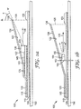
- FIG. 1a depicts a side view of one embodiment of a collimating light engine 100 affixed to back substrate 150 with first adhesive layer 105, according to one aspect of the present disclosure.
- the collimating light engine 100 of FIG. 1a can be suited for continuous production of light engines as described elsewhere.
- Collimating light engine 100 includes a light source 130 and circuitry 145 affixed proximate a first surface of a reflector 110.
- reflector 110 is a flexible reflector, such as a film.
- Light source 130 and circuitry 145 can be disposed on a flexible substrate 140, which is in turn affixed to reflector 110 with second adhesive layer 115.
- Light source 130 is positioned so that the emission optical axis 136 extends perpendicularly from emitting surface 135, and is generally parallel to reflector 110. In another embodiment, the emission optical axis 136 is generally parallel to a transverse plane bisecting the wedge shape formed by a baffle 120 and reflector 110.
- Light source 130 can be any light source that emits light from a surface, e.g., LEDs. Light from surface 135 is generally emitted in a hemispherical pattern from surface 135.
- the collimating light engine can include any suitable light source including, e.g., a surface emitting LED, such as a blue- or UV emitting- LED with a down-converting phosphor to emit white light hemispherically from the surface; individual colored LEDs, such as arrangements of red/green/blue (RGB) LEDs; and others such as described in PCT Patent Application US2008/064133 (Attorney Docket No. 63274WO004) entitled "Backlight and Display System Using Same".
- a visible light emitters such as linear cold cathode fluorescent lamps (CCFLs) or hot cathode fluorescent lamps (HCFLs) can be used instead of or in addition to discrete LED sources as light sources for the disclosed illumination devices.
- CCFLs linear cold cathode fluorescent lamps
- HCFLs hot cathode fluorescent lamps
- hybrid systems such as, for example, (CCFL/LED), including cool white and warm white, CCFL/HCFL, such as those that emit different spectra, may be used.
- the combinations of light emitters may vary widely, and include LEDs and CCFLs, and pluralities such as, for example, multiple CCFLs, multiple CCFLs of different colors, and LEDs and CCFLs.
- Baffle 120 is disposed over light source 130.
- the baffle 120 extends over a portion of reflector 110 so that light source 130 is obscured by baffle 120 when viewed from above at angles less than ⁇ as shown in the Figure. According to one aspect, the light source 130 is obscured from view at angles ⁇ less than 50, 60, 70, 75, or even 85 degrees.
- the baffle 120 is affixed to the flexible substrate 140 with third adhesive layer 125.
- the baffle 120 can also be affixed to reflector 110 with second adhesive layer 115 as shown in the Figure.
- First, second and third adhesive layers 105, 115, 125 can be the same adhesive material, or they can be different.
- any known adhesive material can be used, for example a PSA, a hot-melt, a solvent based, or a curable adhesive can be used. It may be preferred that the thickness of the adhesive material be kept thin, such as less than the thickness of the baffle 120, to keep the overall thickness of collimating light engine 100 small.
- the baffle 120 generally conforms to the reflector 110 and flexible substrate 140 where it is adhered by second and third adhesive layers 115, 125. However, light source 130 projects from flexible substrate 140 and edge 132 contacts baffle 120, which then angles away from reflector 110, forming an exit aperture 128. As shown in the Figure, exit aperture 128 can be defined by projecting a baffle end 126 onto reflector 110. In one embodiment, exit aperture 128 can include supporting structures such as ribs or posts (not shown) to support baffle end 126.
- a transport region 155 extending over a portion of reflector 110 can provide for additional mixing of light emitted through the exit aperture 128, when several collimating light engines 100 are disposed in an array, as described elsewhere.
- the transport region 155 is the portion of reflector 110 beyond the projection of baffle end 126 onto reflector 110 along exit aperture 128, as indicated in the Figure.
- transport region 155 is shown in the Figures as extending beyond the projection of the baffle end 126, it is to be understood that the transport region can be a separation between the baffles of adjacent collimating light engines, as described elsewhere with reference to FIG. 4 and FIG. 5 .
- the transport region can include any portion of the light engine that is between angled baffles and serves to mix light from a light engine.
- the material including reflector 110 and baffle 120 can be the same or different.
- at least one of the reflector 110 and baffle 120 include surface reflectors such as a metallic film or a metallized polymeric film.
- at least one of the reflector 110 and baffle 120 include interference reflectors such as organic or inorganic multilayer optical films, as described for example in U.S. Patent No. 5,882,774 .
- at least one of the reflector 110 and baffle 120 include semi-specular reflectors, described for example in co-pending PCT Patent Application No. US2008/064115 (Attorney Docket No. 63032WO003), and also in co-pending Attorney Docket No. 63957US002 entitled "ILLUMINATION DEVICE WITH PROGRESSIVE INJECTION", filed on an even date herewith.
- Baffle 120 is a reflective baffle having a first side 122 facing light source 130 and a second side 124 opposite the first side 122.
- the reflective properties of first and second sides 122, 124 can be the same or different.
- at least one of the first and second sides 122, 124 can be selected from a specular reflector, a semi-specular reflector, and a diffuse reflector.
- the baffle includes an ESR film, and both first and second sides 122, 124 have similar reflective properties.
- the collimating light engine can include any suitable reflector and baffle.
- the reflector can be made from a stiff metal substrate with a high reflectivity coating, or the reflector and the baffle can be made of a high reflectivity film which can be laminated to a supporting substrate.
- Suitable high reflectivity materials include VikuitiTM Enhanced Specular Reflector (ESR) multilayer polymeric film available from 3M Company; a film made by laminating a barium sulfate-loaded polyethylene terephthalate film (2 mils thick) to VikuitiTM ESR film using a 0.4 mil thick isooctylacrylate acrylic acid pressure sensitive adhesive, the resulting laminate film referred to herein as "EDR II” film; E-60 series LumirrorTM polyester film available from Toray Industries, Inc.; porous polytetrafluoroethylene (PTFE) films, such as those available from W. L.
- ESR VikuitiTM Enhanced Specular Reflector
- Baffle 120 can have non-uniform optical or other physical properties.
- the portion supported by edge 132 of light source 130 and continuing to baffle end 126 can include materials such as a high bending modulus film, to provide added stiffness in this portion.
- the reflective properties of at least one of the first and second side 122, 124 can vary over the baffle.
- the portion of baffle 120 near baffle end 126 can be serrated, slit, perforated, embossed, or printed to alter the reflective and/or transmissive properties, as described elsewhere.
- FIG. 1b shows a side view of a collimating light engine 100 affixed to back substrate 150 with first adhesive layer 105, according to another aspect of the disclosure but not according to the invention.
- the collimating light engine 100 of FIG. 1b can be suited for continuous production of light engines as described elsewhere.
- Like numbered elements in FIG. 1b refer to like numbered elements of FIG. 1a .
- Collimating light engine 100 includes a light source 164 affixed to a circuit board 160.
- Light source 164 includes collimating optical element 166, typically a lens, which partially collimates light within a narrow range of angles from optical axis 136.
- the collimating lens can collimate light in either one or two directions, i.e. generally parallel or generally perpendicular to the transverse plane parallel to reflector 110.
- Circuit board 160 projects from reflector 110 and provides support for baffle 120 at edge 162.
- light from light source 164 is sufficiently collimated that light does not reflect from first side 122 of baffle 120, and the reflectivity of first side 122 has little effect on the performance of the collimating light engine 100. In one embodiment, light from light source 164 is sufficiently collimated that light does not reflect from reflector 110 in the region between collimating optical element 166 and exit aperture 128, and the reflectivity of reflector 110 in this region has little effect on the performance of the collimating light engine 100.
- FIG. 1c shows a side view of adjacent light engines 101 which include a first collimating light engine 100 affixed to reflector 110 with second adhesive layer 115, according to another aspect of the disclosure.
- the adjacent light engines 101 of FIG. 1c can be suited for continuous production of light engines as described elsewhere.
- a portion of an adjacent second collimating light engine 100' is shown to indicate placement relative to first collimating light engine 100, as described elsewhere.
- Like numbered elements in FIG. 1c refer to like numbered elements of FIG. 1a .
- shaped baffle 170 comprises a parabolic shape as shown in the Figure, which can be useful to partially collimate light parallel to reflector 110.
- Shaped baffle 170 is a reflective baffle having a first side 172 facing light source 130 and a second side 174 opposite the first side 172.
- the reflective properties of first and second sides 172, 174 can be the same or different.
- at least one of the first and second sides 172, 174 can be selected from a specular reflector, a semi-specular reflector, and a diffuse reflector.
- the baffle includes an ESR film, and both first and second sides 172, 174 have similar reflective properties.
- Shaped baffle 170 can be affixed to flexible substrate 140 with third adhesive 125. Additionally, second adhesive layer 115 can extend beyond flexible substrate 140, as shown in FIG. 1a , to provide an additional region for affixing shaped baffle 170.
- Transport region 155 separates first and second collimating light engines 100, 100'. The length of transport region 155 can be chosen to mix light from light source 130 in a direction parallel to the plane of reflector 110. In one embodiment, collimating light engines 100, 100' can be made on reflector 110 in a continuous fashion, and separated at the transport region 155, as described elsewhere. The collimating light engines can then be affixed to a back substrate 150 with a first adhesive layer 105 as shown in FIG. 1a .
- FIG. 1d shows a side view of adjacent light engines 101 that include a first collimating light engine 100 affixed to reflector 110 with second adhesive layer 115, according to another aspect of the disclosure.
- the adjacent light engines 101 of FIG. 1d can be suited for continuous production of light engines as described elsewhere.
- a portion of an adjacent second collimating light engine 100' is shown to indicate placement relative to first collimating light engine 100, as described elsewhere.
- Like numbered elements in FIG. 1d refer to like numbered elements of FIG. 1a .
- shaped baffle 180 compares to baffle 120 of FIG. 1a , but has an additional member between ends 186 and 188, that forms an angle ⁇ 1 with the shaped baffle member supported by edge 132 of light source 130.
- Shaped baffle 180 can be a reflective baffle having a first side 182 facing light source 130, a second side 184 opposite the first side 182, third side 187 contiguous with first side 182, and fourth side 189 contiguous with second side 184.
- the reflective properties of first through fourth sides 182, 184, 187, 189 can be the same or different.
- at least one of the first through fourth sides 182, 184, 187, 189 can be selected from a specular reflector, a semi-specular reflector, and a diffuse reflector.
- the baffle includes an ESR film, and first through fourth sides 182, 184, 187, 189 have similar reflective properties.
- Shaped baffle 180 can be affixed to flexible substrate 140 with third adhesive 125. Additionally, second adhesive layer 115 can extend beyond flexible substrate 140, as shown in FIG. 1a , to provide an additional region for affixing shaped baffle 180.
- Transport region 155 separates first and second collimating light engines 100, 100'. The length of transport region 155 can be chosen to mix light from light source 130 in a direction parallel to the plane of reflector 110. In one embodiment, collimating light engines 100, 100' can be made on reflector 110 in a continuous fashion, and separated at the transport region 155, as described elsewhere. The collimating light engines can then be affixed to a back substrate 150 with a first adhesive layer 105 as shown in FIG. 1a .
- FIG. 1e shows a side view of adjacent light engines 101 which include a first collimating light engine 100 affixed to reflector 110 with second adhesive layer 115, according to another aspect of the disclosure.
- the adjacent light engines 101 of FIG. 1e can be suited for continuous production of light engines as described elsewhere.
- a portion of an adjacent second collimating light engine 100' is shown to indicate placement relative to first collimating light engine 100, as described elsewhere.
- Like numbered elements in FIG. 1e refer to like numbered elements of FIG. 1a and FIG. 1d .
- FIG. 1e shows the collimating light engine of FIG. 1d where angle ⁇ 1 of shaped baffle 180 is increased to angle ⁇ 2, and length of additional member between ends 186 and 188 is decreased from FIG. 1d .
- additional member between ends 186 and 188 of shaped baffle 180 can re-direct light that is traveling in a direction generally toward light emitting surface 135 along reflector 110, as described elsewhere.
- collimating light engines 100, 100' can be made on reflector 110 in a continuous fashion, and separated at the transport region 155, as described elsewhere. The collimating light engines can then be affixed to a back substrate 150 with a first adhesive layer 105 as shown in FIG. 1a .
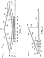
- FIG. If shows a side view of light engine 101 which includes a collimating light engine 100 affixed to reflector 110 with second adhesive layer 115, according to another aspect of the disclosure.
- a second collimating light engine 100' (not shown) can be disposed adjacent collimating light engine 100 in a manner similar to that shown in FIG. 1e .
- the light engine 101 of FIG. 1f can be suited for continuous production of light engines as described elsewhere.
- Like numbered elements in FIG. If refer to like numbered elements of FIG. 1a and FIG. 1e .
- FIG. If shows light sources 130, 130' and circuitry 145, 145' affixed proximate different ends of flexible substrate 140.
- Flexible substrate 140 is affixed to reflector 110 with second adhesive layer 115.
- Emitting surfaces 135, 135' of light sources 130, 130' are disposed to emit light in opposite directions along reflector 110.
- shaped baffle 190 is formed as a unitary structure, made by folding a film.
- first side 192 is contiguous with third, fourth and fifth sides 197, 197', 192'; second side 194 is contiguous with sixth, seventh and eighth sides 199, 199', 194'.
- Shaped baffle 190 is a reflective baffle having a first side 192 facing light source 130, a second side 194 opposite the first side 192.
- the reflective properties of first through eighth sides 192, 194, 197, 199, 197', 199', 192', 194' can be the same or different.
- first through eighth sides 192, 194, 197, 199, 197', 199', 192', 194' can be selected from a specular reflector, a semi-specular reflector, and a diffuse reflector.
- the baffle includes an ESR film, and first through eighth sides 192, 194, 197, 199, 197', 199', 192', 194' have similar reflective properties.
- additional members between ends 196, 198 and 196' of shaped baffle 190 can re-direct light into a desired direction.
- first light ray 161 traveling in a direction generally parallel along reflector 110, can be re-directed in a direction generally away from reflector 110, as shown by second light ray 162.
- collimating light engines 100, 100' can be made on reflector 110 in a continuous fashion, and separated at the transport region 155, as described elsewhere. The collimating light engines can then be affixed to a back substrate 150 with a first adhesive layer 105 as shown in FIG. 1a
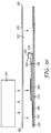
- FIG. 2 shows a side view of a collimating light engine 200 according to another aspect of the disclosure.
- the collimating light engine 200 of FIG. 2 can be particularly well-suited for continuous production of light engines as described elsewhere.
- Collimating light engine 200 includes a light source 230 and circuitry 245 affixed proximate a first surface of reflector 210.
- Light source 230 is positioned as described with reference to light source 130 of FIG. 1a .
- Light source 230 projects from flexible substrate 240 and edge 232 contacts baffle 220, which then angles away from reflector 210, forming exit aperture 228.
- a transport region 255 extending over a portion of reflector 210 can provide for additional mixing of light emitted through an exit aperture 228, when several collimating light engines 200 are disposed in an array, as described elsewhere.
- the transport region 255 is the portion of reflector 210 beyond the projection of baffle end 226 onto reflector 210 along exit aperture 228, as indicated in the Figure.
- Collimating light engine 200 optionally includes first adhesive layer 205 disposed on reflector 210 to facilitate attachment of collimating light engine 200 to another surface, for example the interior of a backlight cavity.
- Optional adhesive layer 205 if included, can include a release liner (not shown) to protect the adhesive until needed.
- light source 230 and circuitry 245 can be disposed on a flexible substrate 240, which is in turn affixed to reflector 210 with second adhesive layer 215.
- circuitry 245 can be disposed directly on reflector 210 by, for example, plating or depositing the circuitry as known in the art.
- flexible substrate 240 and second adhesive layer 215 are replaced by a tie-layer known to improve adhesion of circuitry formed directly on a reflector.
- baffle 220 is disposed over light source 230.
- the baffle 220 extends over a portion of reflector 210 as described with reference to viewing angle ⁇ of FIG. 1a .
- baffle 220 is contiguous with reflector 210, and is formed from the same material, for example, by folding reflector 210 at crease 217 to form baffle 220 which is supported by light source 230 at edge 232.
- baffle 220 is bonded to reflector 210 at crease 217, for example by thermal, ultrasonic, solvent or mechanical means.
- a preferred embodiment includes a contiguous baffle 220 and reflector 210 formed by folding at crease 217.
- a second light source can be disposed proximate the transport region, facing the first light source.
- a second baffle can be disposed over the second light source, to result in a pair of collimating light engines including the same reflector and the same transport region, and in facing relationship to each other.
- Baffle 220 is a reflective baffle having a first side 222 facing light source 230 and a second side 224 opposite the first side 222.
- the reflective properties of first and second sides 222, 224 can be the same or different.
- at least one of the first and second sides 222, 224 can be selected from a specular reflector, a semi-specular reflector, and a diffuse reflector.
- the baffle includes an ESR film, and both first and second sides 222, 224 have similar reflective properties.
- Baffle 220 can have non-uniform optical or other physical properties.
- the portion supported by edge 232 and continuing to baffle end 226 can include materials such as a high bending modulus film, to provide added stiffness in this portion.
- the reflective properties of at least one of the first and second side 222, 224 can vary over the baffle.
- the portion of baffle 220 near baffle end 226 can be serrated, slit, perforated, embossed, or printed to alter the reflective and/or transmissive properties, as described elsewhere.
- FIGS. 3a-3g show selected steps in a process for producing collimating light engines according to one aspect of the disclosure.
- the generalized process steps described with reference to FIGS. 3a-3g can be performed in either a continuous or a step-wise manner.
- FIG. 3a shows a plurality of light sources 330 having light emitting surfaces 335 arranged in light source arrays 336 disposed on flexible substrate 340. Any number of light sources 330 arranged in any number of light source arrays 336 can be associated with circuitry 345.
- flexible substrate 340 can be a continuous substrate, such as a roll of material, so that the elements shown in the Figure are repeated down the length of the roll. In another embodiment, flexible substrate 340 can be a continuous substrate, such as a roll of material, so that the elements shown in the Figure are repeated across the width of the roll.
- Circuitry 345 can be directly formed on flexible substrate 340, and is connected to address light source arrays 336.
- Light source arrays 336 can include identical light sources 330, or individual light sources 330 can be different, for example different color LED light sources as described elsewhere.
- individual light sources 330 can be controlled independently by circuitry 345.
- each light source array 336 can be controlled independently by circuitry 345.
- FIG. 3b shows a side-view of the flexible substrate 340 with attached circuitry 345, light source 330 and edge 332, and emitting surface 335 of FIG. 3a .
- a third adhesive layer 315 is applied to a bottom surface of flexible substrate 340.
- the article shown in FIG. 3b can then be adhered to a reflector 310 as shown in FIG. 3c by contacting the third adhesive layer 315 with a first side of reflector 310.
- a first adhesive layer 305 is applied to the second side of reflector 310. In one embodiment, the first adhesive layer 305 is applied before contacting third adhesive layer 315.
- a release liner (not shown) can be used to protect the free surface of first adhesive layer 305.
- FIG. 3d shows the article of FIG.
- a baffle 320 is positioned over the article of FIG. 3d , and a compliant material 301, such as a rubber roller or sheet, is used to press the baffle 320 against second adhesive layer 325 as shown in FIG. 3f .
- Baffle 320 becomes adhered to the article of FIG. 3d , forcing baffle 320 into contact with edge 332 of light source 330, raising end 326 to form exit aperture 328.
- FIG. 3g shows a completed collimating light engine 300 similar to collimating light engine 100 shown in FIG. 1a , and like numbered elements correspond.
- slight variations in the procedure outlined in FIGS 3a-3f can be used to produce any of the collimating light engines described with reference to FIGS. 1a-1f .
- Individual collimating light engines can be separated from a continuous roll, for example by cutting adjacent the transport region 155.
- Collimating light engines according to the embodiments described with reference to FIG. 2 can be produced by a method similar to FIGS. 3a-f , but with fewer steps.
- the steps shown in FIGS. 3a-3b are followed, and the article of FIG. 3b is adhered to reflector 310.
- Reflector 310 is then folded and first adhesive layer 305 is applied as shown in FIG. 2 .
- the step shown in FIG. 3a is performed directly on reflector 310 as described elsewhere and reflector 310 is then folded and first adhesive layer 305 is applied as shown in FIG. 2 .
- FIG. 4 shows a perspective view of a lighting element 401 that includes collimating light engines 400 and 400' disposed on back substrate 450.
- Collimating light engine 400 includes reflector 410 affixed to back substrate 450, baffle 420, and light source arrays 436a-d including individual light sources 430.
- baffle edge 426 onto reflector 410 defines transport region 455 between adjacent collimating light engines 400 and 400'.
- the size of transport region 455 can be adjusted to achieve the desired light uniformity between light engines.
- Collimating light engine 400' includes similar components (labeled with primed numbers), and as shown in the Figure, additional light engines can be added to increase the size of the lighting element as desired.
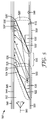
- FIG. 5 shows the path of several representative light rays within a hollow backlight 501 that has a pair of collimating light engines 500, 500' disposed on a back substrate 550 within hollow cavity 502.
- Collimating light engines 500, 500' include baffles 520, 520', baffle edge 526, 526', exit apertures 528, 528', first side 524, 524', and second side 522, 522', respectively, as described elsewhere.
- Light rays AB, AC, AD, AE, and AF are injected into hollow cavity 502 by light source 530 disposed within first collimating light engine 500.
- FIG. 5 shows the path of several representative light rays within a hollow backlight 501 that has a pair of collimating light engines 500, 500' disposed on a back substrate 550 within hollow cavity 502.
- Collimating light engines 500, 500' include baffles 520, 520', baffle edge 526, 526', exit apertures 528, 528',
- light source 530 is shown to be positioned between baffle 520 and a reflective substrate 510, and injects light in a direction generally along the length of the hollow cavity 502.
- light source 530 can be located below the plane defined by reflective substrate 510, and positioned to inject light generally perpendicularly to the length of the hollow cavity, to reflect from baffle 520 and be re-directed along the length of the hollow cavity (not shown).
- Light source 530 can be a surface emitting LED, for example a blue- or UV emitting- LED with a down-converting phosphor to emit white light hemispherically from the surface, or others as described elsewhere.
- first light ray AB reflects from second side 522 of baffle 520, passes through exit aperture 528, and is directed toward a transmissive front film 540.
- Second light ray AC passes through exit aperture 528 and is directed toward transmissive front film 540 without reflection.
- Third light ray AD passes through exit aperture 528, reflects from first side 524' of baffle 520' (of second collimating light engine 500'), and is directed toward transmissive front film 540.
- Fourth light ray AE reflects from reflective substrate 510 within first collimating light engine 500, passes through exit aperture 528, and is directed toward transmissive front film 540.
- a fifth light ray AF passes through exit aperture 528, reflects from back reflector within transport region 555, reflects from first side 524' of baffle 520' (of second collimating light engine 500'), and is directed toward transmissive front film 540.
- each light ray AB, AC, AD, AE, AF can pass through additional optical films 544 before exiting hollow backlight 501 through output surface 546.
- Baffles 520, 520' are positioned so that light rays from first light source 530 are generally confined to travel through hollow cavity 502 within a range of angles ⁇ close to a transverse plane 560.
- Transverse plane 560 is generally parallel to an output surface 546 of hollow backlight 501, and ⁇ ranges within an average deviation angle from the transverse plane 560 in a range from 0 to 40 degrees, or 0 to 30 degrees, or 0 to 15 degrees.
- Light rays (not shown) originating from second light source 530' in second collimating light engine 500' can undergo similar paths to those described above.
- FIG. 5 shows that light injected from the light injector can undergo a variety of reflections before being directed to transmissive front film 540.
- Transmissive front film 540 can be any film suitable for the output surface of a backlight, including a partially transmissive front reflector, a diffuse film, a semi-specular reflector, combinations thereof, or any other suitable films such as described in co-pending Attorney Docket No. 63957US002 entitled "ILLUMINATION DEVICE WITH PROGRESSIVE INJECTION", filed on an even date herewith.
- the combination of these interactions with different surfaces within the hollow cavity 502 provide for a homogenization of the light so that non-uniformities become minimized.
- the transport region 555 serves to allow additional mixing, as well as to enable an increase in the physical separation distance between sources.
- the baffles placed within the hollow cavity serve to "hide" the LED sources from the output surface 546, blocking the direct line of sight view of the sources, as described elsewhere.
- As the length of the transport region increases there is a decrease of radiation flux through the hollow cavity, resulting in a decrease in the brightness of the illumination device. For at least this reason, progressively more light can be injected through additional injection ports to increase the radiation flux, and extend the useable length of the backlight.
- a light sensor 599 can be placed to monitor the light intensity, and any one or several of the light sources can be adjusted by, for example, a feedback circuit.
- Control of the light intensity can be either manual or automatic, and can be used to independently control the light output of various regions of the illumination device.
- a string of side-emitting white LEDs each 0.6 mm high and 1.3 mm long (Nichia NSSW006T LEDs, available from Nichia, Japan) were mounted so that the emitting surface was aligned with an edge of a flex circuit 11.7 mm wide.
- the mounted string of LEDs corresponded to the arrangement shown in FIG. 3a (three parallel banks of seven LEDs in series).
- the flex circuit was adhered to a 28.6 mm wide strip of ESR film (3M Company) so that the emitting surface was 10 mm from the front edge of the ESR film, and the opposite edge of the flex circuit was about 6.8 mm from the back edge of the ESR film.
- Adhesive was applied about 13.7 mm from the back edge of the ESR film, covering about 6.8 mm of the flex circuit, and a second strip of ESR film was pressed onto the adhesive, resulting in a collimating light engine similar to that shown in FIG. 3g .
- the first strip of ESR film corresponds to the reflector 310
- the second strip of ESR film corresponds to the baffle 320 in that Figure.
- the resulting film-based collimating light engine had an exit aperture of 2.2 mm and an overall length of about 29 mm.
- the resulting wedge aspect ratio (ratio of height of exit aperture 328 to height of LED edge 332 above reflector 310) for this film-based collimating light engine was about 2:1.
- the distance between the light emitting surface of the LED (surface 335 in FIG. 3g ) and the front edge of the ESR (reflector 110) depends upon the pitch spacing of the LEDs. For the case of all white LEDs, this distance should be greater or equal to the pitch of the LEDs. For an evenly pitched RGBG color cluster of LEDs, the distance should be greater or equal to 4x the LED pitch.
- the collimating light engine was adhered to an ESR film backplane which had been previously laminated to a 0.004" thick stainless steel shim stock.
- Example 1 Total luminous flux of film-based injectors
- the total luminous flux (TLF) of a film-based light injector was measured in an Optronic integrating sphere by peeling back the upper ESR film that forms the wedge, fully exposing the LEDs so that they could emit into the sphere without obstruction.
- the TLF was measured to be 49.94 lumens, and this TLF value was taken to represent 100% of the ideal light emission from the light engine.
- the upper ESR film was then returned to the original position so that the maximum height of the ESR above the backplane was about 2.2 mm, forming a 2:1 expanding wedge from the LED location.
- the TLF measured in the configuration was 47.95 lumens, indicating that the engine was 96% efficient.
Claims (7)
- Ein Lichtgenerator für gerichtetes Licht, umfassend:einen Reflektor (110) mit einer ersten Oberfläche;eine Lichtquelle (130) und einen Schaltkreis (145), die an dem Reflektor (110) unmittelbar auf die erste Oberfläche geklebt sind; undein reflektierendes Ablenkblech (120), das aus einem einheitlich gefalteten Film über und in Kontakt mit der Lichtquelle (130) geformt ist und sich über einen Teil des Reflektors (110) erstreckt, der Reflektor (110) und das reflektierende Ablenkblech (120) sind zusammen in eine hohle Keilform gebracht, so dass die Lichtquelle (130) bei Winkeln von weniger als 50 Grad gegenüber der Senkrechten zum Reflektor (110) aus der Sicht verdeckt ist.
- Der Lichtgenerator für gerichtetes Licht aus Anspruch 1, worin die Lichtquelle (130) eine optische Emissionsachse hat, die parallel zu der ersten Oberfläche des Reflektors (110) verläuft.
- Der Lichtgenerator für gerichtetes Licht aus Anspruch 1, worin der Reflektor (110) ein Spiegelreflektor oder ein mattglänzender Reflektor ist.
- Der Lichtgenerator für gerichtetes Licht aus Anspruch 1, worin der Reflektor (110) ein Mehrlagen-Interferenzreflektor ist.
- Der Lichtgenerator für gerichtetes Licht aus Anspruch 1, worin die Lichtquelle (130) und der Schaltkreis (145) auf einem als Schaltkreis ausgebildeten Substrat (140) angeordnet sind, und das als Schaltkreis ausgebildete Substrat (140) auf den Reflektor (110) geklebt ist.
- Der Lichtgenerator für gerichtetes Licht aus Anspruch 5, worin das als Schaltkreis ausgebildete Substrat (140) flexibel ist.
- Der Lichtgenerator für gerichtetes Licht aus Anspruch 1, worin das reflektierende Ablenkblech (120) eine der Lichtquelle (130) gegenüber liegende erste Oberfläche und eine zweite Oberfläche gegenüber der ersten Oberfläche hat, und worin mindestens eine von der ersten und zweiten Oberfläche lichtreflektierend ist.
Applications Claiming Priority (2)
| Application Number | Priority Date | Filing Date | Title |
|---|---|---|---|
| US6122508P | 2008-06-13 | 2008-06-13 | |
| PCT/US2009/044102 WO2009151869A2 (en) | 2008-06-13 | 2009-05-15 | Collimating light engine |
Publications (3)
| Publication Number | Publication Date |
|---|---|
| EP2300871A2 EP2300871A2 (de) | 2011-03-30 |
| EP2300871A4 EP2300871A4 (de) | 2012-03-07 |
| EP2300871B1 true EP2300871B1 (de) | 2016-03-09 |
Family
ID=41417338
Family Applications (1)
| Application Number | Title | Priority Date | Filing Date |
|---|---|---|---|
| EP09763160.0A Not-in-force EP2300871B1 (de) | 2008-06-13 | 2009-05-15 | Kollimierende lichtquelle |
Country Status (7)
| Country | Link |
|---|---|
| US (1) | US8608362B2 (de) |
| EP (1) | EP2300871B1 (de) |
| JP (1) | JP5390604B2 (de) |
| KR (1) | KR101571919B1 (de) |
| CN (1) | CN102089702B (de) |
| TW (1) | TWI453355B (de) |
| WO (1) | WO2009151869A2 (de) |
Families Citing this family (22)
| Publication number | Priority date | Publication date | Assignee | Title |
|---|---|---|---|---|
| TWI458918B (zh) | 2007-05-20 | 2014-11-01 | 3M Innovative Properties Co | 具有有利設計特性之薄形中空背光 |
| WO2008144650A1 (en) * | 2007-05-20 | 2008-11-27 | 3M Innovative Properties Company | Collimating light injectors for edge-lit backlights |
| EP2160645A2 (de) | 2007-05-20 | 2010-03-10 | 3M Innovative Properties Company | Licht wiederverwertende anzeigerückbeleuchtung des hohlraum-typs |
| JP5336474B2 (ja) * | 2007-05-20 | 2013-11-06 | スリーエム イノベイティブ プロパティズ カンパニー | 半鏡面構成要素を備えたリサイクル型バックライト |
| EP2160729A2 (de) * | 2007-05-20 | 2010-03-10 | 3M Innovative Properties Company | Weisslicht-rücklichter und dergleichen mit effizienter nutzung von farbigen led-quellen |
| JP5702151B2 (ja) | 2008-02-07 | 2015-04-15 | スリーエム イノベイティブ プロパティズ カンパニー | 構造化フィルムを有する中空のバックライト |
| US9541698B2 (en) * | 2008-02-22 | 2017-01-10 | 3M Innovative Properties Company | Backlights having selected output light flux distributions and display systems using same |
| US8378661B1 (en) | 2008-05-29 | 2013-02-19 | Alpha-Omega Power Technologies, Ltd.Co. | Solar simulator |
| KR20110019388A (ko) * | 2008-06-04 | 2011-02-25 | 쓰리엠 이노베이티브 프로퍼티즈 컴파니 | 경사형 광원을 갖는 중공 백라이트 |
| WO2009151842A2 (en) * | 2008-06-13 | 2009-12-17 | 3M Innovative Properties Company | Illumination device with progressive injection |
| EP2313800A4 (de) | 2008-07-10 | 2014-03-19 | 3M Innovative Properties Co | Viskoelastischer lichtleiter |
| CN102171593A (zh) * | 2008-08-08 | 2011-08-31 | 3M创新有限公司 | 具有粘弹性层的用于控制光的光导 |
| US9709242B2 (en) | 2010-09-23 | 2017-07-18 | Light Prescriptions Innovators, Llc | Shell integrator |
| WO2012063728A1 (ja) * | 2010-11-10 | 2012-05-18 | シャープ株式会社 | 照明装置及び表示装置 |
| WO2013065116A1 (ja) * | 2011-10-31 | 2013-05-10 | 日立コンシューマエレクトロニクス株式会社 | バックライト装置及びこれを用いた液晶表示装置 |
| CN103133918B (zh) | 2011-11-23 | 2015-11-11 | 财团法人工业技术研究院 | 面光源以及可挠性面光源 |
| WO2013080344A1 (ja) * | 2011-11-30 | 2013-06-06 | 日立コンシューマエレクトロニクス株式会社 | バックライト装置及びこれを用いた液晶表示装置 |
| BR112015032298A2 (pt) | 2013-06-27 | 2017-07-25 | Koninklijke Philips Nv | dispositivo de iluminação |
| EP3094920B1 (de) * | 2014-01-06 | 2019-03-13 | Light Prescriptions Innovators, LLC. | Schalenintegrator |
| US10161593B2 (en) | 2014-02-25 | 2018-12-25 | 3M Innovative Properties Company | Solid state lighting device with virtual filament(s) |
| US9046637B1 (en) | 2014-02-25 | 2015-06-02 | 3M Innovative Properties Company | Tubular lighting systems with inner and outer structured surfaces |
| EP3537037A1 (de) * | 2018-03-09 | 2019-09-11 | Teknoluks Endustriyel Metal Ve Plastik San. Tic. Ltd. Sti. | Beleuchtungssystem auf der basis von sichtsperre und mehrfachreflexion für punkt- und richtungslichtquellen |
Citations (1)
| Publication number | Priority date | Publication date | Assignee | Title |
|---|---|---|---|---|
| WO2008013072A1 (fr) * | 2006-07-25 | 2008-01-31 | Showa Denko K.K. | Dispositif émetteur de lumière et dispositif d'affichage l'utilisant |
Family Cites Families (45)
| Publication number | Priority date | Publication date | Assignee | Title |
|---|---|---|---|---|
| US5882774A (en) * | 1993-12-21 | 1999-03-16 | Minnesota Mining And Manufacturing Company | Optical film |
| US6080467A (en) * | 1995-06-26 | 2000-06-27 | 3M Innovative Properties Company | High efficiency optical devices |
| JPH09226043A (ja) * | 1996-02-26 | 1997-09-02 | Mitsui Toatsu Chem Inc | 反射体 |
| JP3442581B2 (ja) * | 1996-08-06 | 2003-09-02 | 株式会社ヒューネット | ネマティック液晶の駆動方法 |
| JP3472417B2 (ja) | 1996-10-22 | 2003-12-02 | シャープ株式会社 | サイド発光型チップledおよび液晶表示装置 |
| US6007209A (en) * | 1997-03-19 | 1999-12-28 | Teledyne Industries, Inc. | Light source for backlighting |
| JP3229250B2 (ja) * | 1997-09-12 | 2001-11-19 | インターナショナル・ビジネス・マシーンズ・コーポレーション | 液晶表示装置における画像表示方法及び液晶表示装置 |
| US6870523B1 (en) * | 2000-06-07 | 2005-03-22 | Genoa Color Technologies | Device, system and method for electronic true color display |
| US6655810B2 (en) * | 2000-06-21 | 2003-12-02 | Fujitsu Display Technologies Corporation | Lighting unit |
| JP3481599B2 (ja) * | 2000-07-14 | 2003-12-22 | 京都電機器株式会社 | 線状照明装置 |
| US7268223B2 (en) * | 2000-09-22 | 2007-09-11 | Wyeth | Isolated nucleic acid molecules which encode a soluble IL-TIF receptor or binding protein which binds to IL-TIF/IL-22, and uses thereof |
| US7776615B2 (en) * | 2001-04-20 | 2010-08-17 | Gl Sciences, Inc. | Method for solid-phase micro extraction and apparatus therefor |
| JP3972680B2 (ja) * | 2001-06-21 | 2007-09-05 | ソニー株式会社 | 照明光学ユニット,液晶プロジェクタ |
| TWI231874B (en) * | 2002-01-15 | 2005-05-01 | Chi Mei Optoelectronics Corp | Liquid crystal display having high brightness and wide viewing angle |
| JP2004095390A (ja) * | 2002-08-30 | 2004-03-25 | Fujitsu Display Technologies Corp | 照明装置及び表示装置 |
| TW589467B (en) * | 2002-09-27 | 2004-06-01 | Litek Opto Electronics Co Ltd | Light collimating system |
| US7182480B2 (en) * | 2003-03-05 | 2007-02-27 | Tir Systems Ltd. | System and method for manipulating illumination created by an array of light emitting devices |
| JP2005157059A (ja) * | 2003-11-27 | 2005-06-16 | Seiko Epson Corp | 照明装置及びプロジェクタ |
| DE102004046696A1 (de) * | 2004-05-24 | 2005-12-29 | Osram Opto Semiconductors Gmbh | Verfahren zur Montage eines Oberflächenleuchtsystems und Oberflächenleuchtsystem |
| KR20050121076A (ko) * | 2004-06-21 | 2005-12-26 | 삼성전자주식회사 | 백라이트 어셈블리 및 이를 이용한 표시장치 |
| KR100576870B1 (ko) * | 2004-08-11 | 2006-05-10 | 삼성전기주식회사 | 질화물 반도체 발광소자 및 제조방법 |
| US7304425B2 (en) * | 2004-10-29 | 2007-12-04 | 3M Innovative Properties Company | High brightness LED package with compound optical element(s) |
| US20060187650A1 (en) * | 2005-02-24 | 2006-08-24 | 3M Innovative Properties Company | Direct lit backlight with light recycling and source polarizers |
| US7478919B2 (en) * | 2005-03-21 | 2009-01-20 | Gamasonic Ltd. | Lamp strip assembly |
| US7311431B2 (en) * | 2005-04-01 | 2007-12-25 | Avago Technologies Ecbu Ip Pte Ltd | Light-emitting apparatus having a plurality of adjacent, overlapping light-guide plates |
| US20060221610A1 (en) | 2005-04-01 | 2006-10-05 | Chew Tong F | Light-emitting apparatus having a plurality of overlapping panels forming recesses from which light is emitted |
| CN1851536A (zh) * | 2005-04-22 | 2006-10-25 | 鸿富锦精密工业(深圳)有限公司 | 背光模组及其光学膜成型方法 |
| TWI258044B (en) * | 2005-06-01 | 2006-07-11 | Au Optronics Corp | Direct-type backlight unit structure |
| US7903194B2 (en) * | 2005-06-24 | 2011-03-08 | 3M Innovative Properties Company | Optical element for lateral light spreading in back-lit displays and system using same |
| KR100667817B1 (ko) | 2005-09-26 | 2007-01-11 | 삼성전자주식회사 | 직하발광형 백라이트 유닛 및 이를 적용한 칼라 필터를사용하지 않는 액정표시장치 |
| KR100784090B1 (ko) * | 2005-10-25 | 2007-12-10 | 엘지이노텍 주식회사 | 발광모듈 및 이를 구비하는 백라이트 유닛 |
| US7868967B2 (en) * | 2005-10-27 | 2011-01-11 | Sharp Kabushiki Kaisha | Light source device, and display device and television receiver therewith |
| US20070139961A1 (en) * | 2005-12-19 | 2007-06-21 | Cheah Chun H | Method and apparatus employing a heat sink, a flexible printed circuit conformed to at least part of the heat sink, and a light source attached to the flexible printed circuit |
| US7525126B2 (en) * | 2006-05-02 | 2009-04-28 | 3M Innovative Properties Company | LED package with converging optical element |
| US7736044B2 (en) * | 2006-05-26 | 2010-06-15 | Avago Technologies General Ip (Singapore) Pte. Ltd. | Indirect lighting device for light guide illumination |
| JP4857945B2 (ja) * | 2006-06-21 | 2012-01-18 | ソニー株式会社 | 面状光源装置及び液晶表示装置組立体 |
| US20080019114A1 (en) | 2006-07-19 | 2008-01-24 | Gert Stuyven | Light source having enhanced mixing |
| JP2008034273A (ja) | 2006-07-31 | 2008-02-14 | E Image Technology Kk | 直下型バックライト用反射板 |
| TWI336799B (en) * | 2006-08-23 | 2011-02-01 | Lite On Technology Corp | Light guide device and light guide plate using the same |
| US20080049445A1 (en) * | 2006-08-25 | 2008-02-28 | Philips Lumileds Lighting Company, Llc | Backlight Using High-Powered Corner LED |
| US7834424B2 (en) * | 2006-09-12 | 2010-11-16 | The Board Of Trustees Of The Leland Stanford Junior University | Extendable connector and network |
| WO2008032275A1 (en) | 2006-09-15 | 2008-03-20 | Koninklijke Philips Electronics N.V. | Flat and thin led-based luminary |
| US8511878B2 (en) * | 2006-10-16 | 2013-08-20 | Koninklijke Philips N.V. | Flat and thin LED-based luminary |
| KR101565934B1 (ko) * | 2008-05-23 | 2015-11-06 | 삼성디스플레이 주식회사 | 백라이트 어셈블리 및 이를 갖는 표시장치 |
| WO2009151842A2 (en) * | 2008-06-13 | 2009-12-17 | 3M Innovative Properties Company | Illumination device with progressive injection |
-
2009
- 2009-05-15 WO PCT/US2009/044102 patent/WO2009151869A2/en active Application Filing
- 2009-05-15 US US12/996,409 patent/US8608362B2/en not_active Expired - Fee Related
- 2009-05-15 CN CN200980126639.1A patent/CN102089702B/zh not_active Expired - Fee Related
- 2009-05-15 JP JP2011513531A patent/JP5390604B2/ja not_active Expired - Fee Related
- 2009-05-15 EP EP09763160.0A patent/EP2300871B1/de not_active Not-in-force
- 2009-05-15 KR KR1020117000539A patent/KR101571919B1/ko not_active IP Right Cessation
- 2009-06-01 TW TW098118071A patent/TWI453355B/zh not_active IP Right Cessation
Patent Citations (1)
| Publication number | Priority date | Publication date | Assignee | Title |
|---|---|---|---|---|
| WO2008013072A1 (fr) * | 2006-07-25 | 2008-01-31 | Showa Denko K.K. | Dispositif émetteur de lumière et dispositif d'affichage l'utilisant |
Also Published As
| Publication number | Publication date |
|---|---|
| WO2009151869A3 (en) | 2010-03-04 |
| JP5390604B2 (ja) | 2014-01-15 |
| KR20110030549A (ko) | 2011-03-23 |
| US8608362B2 (en) | 2013-12-17 |
| KR101571919B1 (ko) | 2015-11-25 |
| EP2300871A2 (de) | 2011-03-30 |
| CN102089702A (zh) | 2011-06-08 |
| JP2011523195A (ja) | 2011-08-04 |
| WO2009151869A8 (en) | 2011-02-10 |
| EP2300871A4 (de) | 2012-03-07 |
| WO2009151869A2 (en) | 2009-12-17 |
| TWI453355B (zh) | 2014-09-21 |
| TW201002987A (en) | 2010-01-16 |
| CN102089702B (zh) | 2014-05-14 |
| US20110075398A1 (en) | 2011-03-31 |
Similar Documents
| Publication | Publication Date | Title |
|---|---|---|
| EP2300871B1 (de) | Kollimierende lichtquelle | |
| JP5457440B2 (ja) | 漸進的注入を有する照明装置 | |
| US7537374B2 (en) | Edge-lit backlight having light recycling cavity with concave transflector | |
| EP2160644B1 (de) | Halbspiegelnde komponenten in rückbeleuchtungseinheiten vom hohlraumtyp mit lichtwiederverwertung | |
| US7815355B2 (en) | Direct-lit backlight having light recycling cavity with concave transflector | |
| US7661862B2 (en) | LCD display backlight using elongated illuminators | |
| US20070047228A1 (en) | Methods of forming direct-lit backlights having light recycling cavity with concave transflector | |
| JP2006286638A (ja) | 複数の隣り合って重なり合う導光板を有する発光装置 | |
| US9477117B2 (en) | Optical lens module and backlight unit | |
| US8206000B2 (en) | Hollow edge-type backlight module with light-emitting array | |
| US20070047219A1 (en) | Direct-lit backlight having light sources with bifunctional diverters | |
| WO2008096979A1 (en) | Light unit and display apparatus having the same | |
| MX2012009374A (es) | Dispositivo de iluminacion, dispositivo de presentacion visual y receptor de television. | |
| US20110032449A1 (en) | Perforated backlight |
Legal Events
| Date | Code | Title | Description |
|---|---|---|---|
| PUAI | Public reference made under article 153(3) epc to a published international application that has entered the european phase |
Free format text: ORIGINAL CODE: 0009012 |
|
| 17P | Request for examination filed |
Effective date: 20110111 |
|
| AK | Designated contracting states |
Kind code of ref document: A2 Designated state(s): AT BE BG CH CY CZ DE DK EE ES FI FR GB GR HR HU IE IS IT LI LT LU LV MC MK MT NL NO PL PT RO SE SI SK TR |
|
| AX | Request for extension of the european patent |
Extension state: AL BA RS |
|
| RIN1 | Information on inventor provided before grant (corrected) |
Inventor name: MEIS, MICHAEL A. Inventor name: BIERNATH, ROLF, W. Inventor name: WHEATLEY, JOHN A. |
|
| DAX | Request for extension of the european patent (deleted) | ||
| A4 | Supplementary search report drawn up and despatched |
Effective date: 20120202 |
|
| RIC1 | Information provided on ipc code assigned before grant |
Ipc: G02F 1/13357 20060101AFI20120127BHEP Ipc: G02F 1/1335 20060101ALI20120127BHEP |
|
| 17Q | First examination report despatched |
Effective date: 20121019 |
|
| GRAP | Despatch of communication of intention to grant a patent |
Free format text: ORIGINAL CODE: EPIDOSNIGR1 |
|
| INTG | Intention to grant announced |
Effective date: 20150731 |
|
| GRAS | Grant fee paid |
Free format text: ORIGINAL CODE: EPIDOSNIGR3 |
|
| GRAA | (expected) grant |
Free format text: ORIGINAL CODE: 0009210 |
|
| AK | Designated contracting states |
Kind code of ref document: B1 Designated state(s): AT BE BG CH CY CZ DE DK EE ES FI FR GB GR HR HU IE IS IT LI LT LU LV MC MK MT NL NO PL PT RO SE SI SK TR |
|
| REG | Reference to a national code |
Ref country code: GB Ref legal event code: FG4D |
|
| REG | Reference to a national code |
Ref country code: AT Ref legal event code: REF Ref document number: 779939 Country of ref document: AT Kind code of ref document: T Effective date: 20160315 Ref country code: CH Ref legal event code: EP |
|
| REG | Reference to a national code |
Ref country code: IE Ref legal event code: FG4D |
|
| REG | Reference to a national code |
Ref country code: DE Ref legal event code: R096 Ref document number: 602009036681 Country of ref document: DE |
|
| REG | Reference to a national code |
Ref country code: LT Ref legal event code: MG4D |
|
| REG | Reference to a national code |
Ref country code: NL Ref legal event code: MP Effective date: 20160309 |
|
| PG25 | Lapsed in a contracting state [announced via postgrant information from national office to epo] |
Ref country code: NO Free format text: LAPSE BECAUSE OF FAILURE TO SUBMIT A TRANSLATION OF THE DESCRIPTION OR TO PAY THE FEE WITHIN THE PRESCRIBED TIME-LIMIT Effective date: 20160609 Ref country code: ES Free format text: LAPSE BECAUSE OF FAILURE TO SUBMIT A TRANSLATION OF THE DESCRIPTION OR TO PAY THE FEE WITHIN THE PRESCRIBED TIME-LIMIT Effective date: 20160309 Ref country code: FI Free format text: LAPSE BECAUSE OF FAILURE TO SUBMIT A TRANSLATION OF THE DESCRIPTION OR TO PAY THE FEE WITHIN THE PRESCRIBED TIME-LIMIT Effective date: 20160309 Ref country code: GR Free format text: LAPSE BECAUSE OF FAILURE TO SUBMIT A TRANSLATION OF THE DESCRIPTION OR TO PAY THE FEE WITHIN THE PRESCRIBED TIME-LIMIT Effective date: 20160610 Ref country code: HR Free format text: LAPSE BECAUSE OF FAILURE TO SUBMIT A TRANSLATION OF THE DESCRIPTION OR TO PAY THE FEE WITHIN THE PRESCRIBED TIME-LIMIT Effective date: 20160309 |
|
| REG | Reference to a national code |
Ref country code: AT Ref legal event code: MK05 Ref document number: 779939 Country of ref document: AT Kind code of ref document: T Effective date: 20160309 |
|
| PG25 | Lapsed in a contracting state [announced via postgrant information from national office to epo] |
Ref country code: NL Free format text: LAPSE BECAUSE OF FAILURE TO SUBMIT A TRANSLATION OF THE DESCRIPTION OR TO PAY THE FEE WITHIN THE PRESCRIBED TIME-LIMIT Effective date: 20160309 Ref country code: BE Free format text: LAPSE BECAUSE OF NON-PAYMENT OF DUE FEES Effective date: 20160531 Ref country code: SE Free format text: LAPSE BECAUSE OF FAILURE TO SUBMIT A TRANSLATION OF THE DESCRIPTION OR TO PAY THE FEE WITHIN THE PRESCRIBED TIME-LIMIT Effective date: 20160309 Ref country code: PL Free format text: LAPSE BECAUSE OF FAILURE TO SUBMIT A TRANSLATION OF THE DESCRIPTION OR TO PAY THE FEE WITHIN THE PRESCRIBED TIME-LIMIT Effective date: 20160309 Ref country code: LV Free format text: LAPSE BECAUSE OF FAILURE TO SUBMIT A TRANSLATION OF THE DESCRIPTION OR TO PAY THE FEE WITHIN THE PRESCRIBED TIME-LIMIT Effective date: 20160309 Ref country code: LT Free format text: LAPSE BECAUSE OF FAILURE TO SUBMIT A TRANSLATION OF THE DESCRIPTION OR TO PAY THE FEE WITHIN THE PRESCRIBED TIME-LIMIT Effective date: 20160309 |
|
| PG25 | Lapsed in a contracting state [announced via postgrant information from national office to epo] |
Ref country code: IS Free format text: LAPSE BECAUSE OF FAILURE TO SUBMIT A TRANSLATION OF THE DESCRIPTION OR TO PAY THE FEE WITHIN THE PRESCRIBED TIME-LIMIT Effective date: 20160709 Ref country code: EE Free format text: LAPSE BECAUSE OF FAILURE TO SUBMIT A TRANSLATION OF THE DESCRIPTION OR TO PAY THE FEE WITHIN THE PRESCRIBED TIME-LIMIT Effective date: 20160309 |
|
| PG25 | Lapsed in a contracting state [announced via postgrant information from national office to epo] |
Ref country code: AT Free format text: LAPSE BECAUSE OF FAILURE TO SUBMIT A TRANSLATION OF THE DESCRIPTION OR TO PAY THE FEE WITHIN THE PRESCRIBED TIME-LIMIT Effective date: 20160309 Ref country code: CZ Free format text: LAPSE BECAUSE OF FAILURE TO SUBMIT A TRANSLATION OF THE DESCRIPTION OR TO PAY THE FEE WITHIN THE PRESCRIBED TIME-LIMIT Effective date: 20160309 Ref country code: PT Free format text: LAPSE BECAUSE OF FAILURE TO SUBMIT A TRANSLATION OF THE DESCRIPTION OR TO PAY THE FEE WITHIN THE PRESCRIBED TIME-LIMIT Effective date: 20160711 Ref country code: SK Free format text: LAPSE BECAUSE OF FAILURE TO SUBMIT A TRANSLATION OF THE DESCRIPTION OR TO PAY THE FEE WITHIN THE PRESCRIBED TIME-LIMIT Effective date: 20160309 Ref country code: RO Free format text: LAPSE BECAUSE OF FAILURE TO SUBMIT A TRANSLATION OF THE DESCRIPTION OR TO PAY THE FEE WITHIN THE PRESCRIBED TIME-LIMIT Effective date: 20160309 |
|
| REG | Reference to a national code |
Ref country code: DE Ref legal event code: R097 Ref document number: 602009036681 Country of ref document: DE |
|
| PG25 | Lapsed in a contracting state [announced via postgrant information from national office to epo] |
Ref country code: BE Free format text: LAPSE BECAUSE OF FAILURE TO SUBMIT A TRANSLATION OF THE DESCRIPTION OR TO PAY THE FEE WITHIN THE PRESCRIBED TIME-LIMIT Effective date: 20160309 Ref country code: IT Free format text: LAPSE BECAUSE OF FAILURE TO SUBMIT A TRANSLATION OF THE DESCRIPTION OR TO PAY THE FEE WITHIN THE PRESCRIBED TIME-LIMIT Effective date: 20160309 Ref country code: LU Free format text: LAPSE BECAUSE OF FAILURE TO SUBMIT A TRANSLATION OF THE DESCRIPTION OR TO PAY THE FEE WITHIN THE PRESCRIBED TIME-LIMIT Effective date: 20160515 |
|
| REG | Reference to a national code |
Ref country code: CH Ref legal event code: PL |
|
| PLBE | No opposition filed within time limit |
Free format text: ORIGINAL CODE: 0009261 |
|
| STAA | Information on the status of an ep patent application or granted ep patent |
Free format text: STATUS: NO OPPOSITION FILED WITHIN TIME LIMIT |
|
| PG25 | Lapsed in a contracting state [announced via postgrant information from national office to epo] |
Ref country code: CH Free format text: LAPSE BECAUSE OF NON-PAYMENT OF DUE FEES Effective date: 20160531 Ref country code: LI Free format text: LAPSE BECAUSE OF NON-PAYMENT OF DUE FEES Effective date: 20160531 Ref country code: DK Free format text: LAPSE BECAUSE OF FAILURE TO SUBMIT A TRANSLATION OF THE DESCRIPTION OR TO PAY THE FEE WITHIN THE PRESCRIBED TIME-LIMIT Effective date: 20160309 |
|
| 26N | No opposition filed |
Effective date: 20161212 |
|
| REG | Reference to a national code |
Ref country code: IE Ref legal event code: MM4A |
|
| PG25 | Lapsed in a contracting state [announced via postgrant information from national office to epo] |
Ref country code: BG Free format text: LAPSE BECAUSE OF FAILURE TO SUBMIT A TRANSLATION OF THE DESCRIPTION OR TO PAY THE FEE WITHIN THE PRESCRIBED TIME-LIMIT Effective date: 20160609 |
|
| GBPC | Gb: european patent ceased through non-payment of renewal fee |
Effective date: 20160609 |
|
| REG | Reference to a national code |
Ref country code: FR Ref legal event code: ST Effective date: 20170131 |
|
| PG25 | Lapsed in a contracting state [announced via postgrant information from national office to epo] |
Ref country code: FR Free format text: LAPSE BECAUSE OF NON-PAYMENT OF DUE FEES Effective date: 20160531 |
|
| PG25 | Lapsed in a contracting state [announced via postgrant information from national office to epo] |
Ref country code: IE Free format text: LAPSE BECAUSE OF NON-PAYMENT OF DUE FEES Effective date: 20160515 Ref country code: GB Free format text: LAPSE BECAUSE OF NON-PAYMENT OF DUE FEES Effective date: 20160609 Ref country code: SI Free format text: LAPSE BECAUSE OF FAILURE TO SUBMIT A TRANSLATION OF THE DESCRIPTION OR TO PAY THE FEE WITHIN THE PRESCRIBED TIME-LIMIT Effective date: 20160309 |
|
| PGFP | Annual fee paid to national office [announced via postgrant information from national office to epo] |
Ref country code: DE Payment date: 20170509 Year of fee payment: 9 |
|
| PG25 | Lapsed in a contracting state [announced via postgrant information from national office to epo] |
Ref country code: HU Free format text: LAPSE BECAUSE OF FAILURE TO SUBMIT A TRANSLATION OF THE DESCRIPTION OR TO PAY THE FEE WITHIN THE PRESCRIBED TIME-LIMIT; INVALID AB INITIO Effective date: 20090515 Ref country code: CY Free format text: LAPSE BECAUSE OF FAILURE TO SUBMIT A TRANSLATION OF THE DESCRIPTION OR TO PAY THE FEE WITHIN THE PRESCRIBED TIME-LIMIT Effective date: 20160309 |
|
| PG25 | Lapsed in a contracting state [announced via postgrant information from national office to epo] |
Ref country code: MT Free format text: LAPSE BECAUSE OF NON-PAYMENT OF DUE FEES Effective date: 20160531 Ref country code: MC Free format text: LAPSE BECAUSE OF FAILURE TO SUBMIT A TRANSLATION OF THE DESCRIPTION OR TO PAY THE FEE WITHIN THE PRESCRIBED TIME-LIMIT Effective date: 20160309 Ref country code: TR Free format text: LAPSE BECAUSE OF FAILURE TO SUBMIT A TRANSLATION OF THE DESCRIPTION OR TO PAY THE FEE WITHIN THE PRESCRIBED TIME-LIMIT Effective date: 20160309 Ref country code: MK Free format text: LAPSE BECAUSE OF FAILURE TO SUBMIT A TRANSLATION OF THE DESCRIPTION OR TO PAY THE FEE WITHIN THE PRESCRIBED TIME-LIMIT Effective date: 20160309 |
|
| REG | Reference to a national code |
Ref country code: DE Ref legal event code: R119 Ref document number: 602009036681 Country of ref document: DE |
|
| PG25 | Lapsed in a contracting state [announced via postgrant information from national office to epo] |
Ref country code: DE Free format text: LAPSE BECAUSE OF NON-PAYMENT OF DUE FEES Effective date: 20181201 |