EP2300331B1 - Anklemmbare kappe mit vorragender lasche für den hals eines behälters - Google Patents
Anklemmbare kappe mit vorragender lasche für den hals eines behälters Download PDFInfo
- Publication number
- EP2300331B1 EP2300331B1 EP09766049A EP09766049A EP2300331B1 EP 2300331 B1 EP2300331 B1 EP 2300331B1 EP 09766049 A EP09766049 A EP 09766049A EP 09766049 A EP09766049 A EP 09766049A EP 2300331 B1 EP2300331 B1 EP 2300331B1
- Authority
- EP
- European Patent Office
- Prior art keywords
- skirt
- tab
- neck
- axis
- stopper
- Prior art date
- Legal status (The legal status is an assumption and is not a legal conclusion. Google has not performed a legal analysis and makes no representation as to the accuracy of the status listed.)
- Active
Links
Images


Classifications
-
- B—PERFORMING OPERATIONS; TRANSPORTING
- B65—CONVEYING; PACKING; STORING; HANDLING THIN OR FILAMENTARY MATERIAL
- B65D—CONTAINERS FOR STORAGE OR TRANSPORT OF ARTICLES OR MATERIALS, e.g. BAGS, BARRELS, BOTTLES, BOXES, CANS, CARTONS, CRATES, DRUMS, JARS, TANKS, HOPPERS, FORWARDING CONTAINERS; ACCESSORIES, CLOSURES, OR FITTINGS THEREFOR; PACKAGING ELEMENTS; PACKAGES
- B65D41/00—Caps, e.g. crown caps or crown seals, i.e. members having parts arranged for engagement with the external periphery of a neck or wall defining a pouring opening or discharge aperture; Protective cap-like covers for closure members, e.g. decorative covers of metal foil or paper
- B65D41/02—Caps or cap-like covers without lines of weakness, tearing strips, tags, or like opening or removal devices
- B65D41/16—Snap-on caps or cap-like covers
- B65D41/18—Snap-on caps or cap-like covers non-metallic, e.g. made of paper or plastics
- B65D41/185—Snap-on caps or cap-like covers non-metallic, e.g. made of paper or plastics with integral internal sealing means
Definitions
- the present invention relates to a cap for a container neck.
- the invention relates more particularly to so-called “snap” or “snap” plugs, ie plugs comprising a tubular skirt adapted to be removably clipped internally around the neck of a container, in contrast to Screw caps, for example.
- This type of caps an example of which is provided by FR-A-1,484,391 frequently includes a tab projecting from the outside of the skirt, so that the user can apply a manual drive force to unclip the cap.
- the extent and the angular position of the tab following the periphery of the skirt are advantageously predetermined according to other characteristics of the cap associated with its opening. For example, by providing that the tab extends less than a quarter of a circle around the central axis of the skirt, and this on the front side of the cap, that is to say the side intended to be turned into service to the user, it then intuitively understands that the cap is tipped backwards using the tab.
- the heads tend to catch the plugs crooked and, above all, they are unable to center accurately on the neck of the container before putting them on, because the presence of the tab shifts "artificially" the position of the central axis of the head with respect to the central axis of the skirt. The quality of the bottling is compromised.
- the object of the present invention is to provide a miter clip cap, of the type mentioned above, which can be set up accurately and efficiently by conventional bottling heads.
- the invention relates to a cap for a container neck, as defined in claim 1.
- the idea underlying the invention is to maintain good visibility of the tab to the attention of the user, while providing the skirt with a gripping collar for a conventional bottling head, the collar being dimensioned to perfectly center the skirt in this head.
- the circular profile of the flange runs over more than a semicircle around the central axis of the skirt, which ensures a sufficient gripping range for the bottling heads, while at the same time, this collar has a radial dimension, relative to the central axis of the skirt, equal to the maximum radial dimension of the tab, which allows the flange to compensate for the transverse offset of the position of the axis of the head, related to the presence of the tab.
- the flange has a radial extent, with respect to the skirt, which is equal to the maximum radial extent of the tab.
- a plug 1 adapted to be releasably clipped onto a neck 2 of a container, the plug 1 being generally referred to as "snap plug” or “snap plug".
- the neck 2 is integral with the rest of the container, especially when the latter is a glass or plastic bottle as on the figure 1 , or adapted to be permanently attached to a wall of the container, at an opening through this wall.
- the plug 1 and the neck 2 have respective generally tubular shapes, whose central longitudinal axes are substantially merged, under the reference XX, when the cap is fixed on the neck.
- the following description is oriented by considering that the terms “upper” and “top” correspond to a direction generally parallel to the axis XX and from the body of the container to its neck 2, that is to say say a direction directed towards the upper part of figures 1 , 3 and 4 , while the terms “lower” and “lower” correspond to an opposite direction.
- the neck 2 comprises a generally cylindrical body 4 with a circular base of axis XX. As shown in phantom only on the right side of the Figures 3 and 4 the body 4 delimits, at its upper end, a rim 3 at which the liquid contained in the container is intended to be poured. On the outer face of the body 4, the neck 2 has, at its upper end, an edge 5 and, in its current portion, a boss 6, this edge and this boss both extending radially outwardly from the body.
- the plug 1 is made of a semi-rigid plastic material, such as polypropylene or polyethylene, shaped by molding.
- the plug 1, considered clipped on the neck 2 is open at its lower end and closed at its upper end by a bottom wall 10, at the outer periphery of which extends axially downwardly a tubular skirt 12 centered on the XX axis and, in the example considered here, a generally annular section with a circular base.
- the bottom wall 10 extends above and across the neck, while the skirt 12 externally surrounds the body 4 of the neck.
- the skirt 12 is provided with an outer tab 14, which extends radially projecting outwardly from the cylindrical outer side face 12A of the skirt.
- This tab 14 runs, along the outer periphery of the skirt, only on a restricted peripheral portion 12 1 of the skirt 12, this portion being subsequently considered as the front side of the cap 1 to the extent that this side is intended for service to be directed to the user.
- the portion 12 1 is extended on a non-zero angle, in practice greater than at least a few degrees, and less than 90 °. In the exemplary embodiment considered in the figures, the portion 12 1 is extended over approximately 50 °.
- the tab 14 comprises, firstly, a running portion 14 1 , whose outer profile, in cross section to the axis XX, is rectilinear in a direction orthoradial to the axis XX and, secondly, two end portions 14 2 , whose outer profile, always in cross section along the axis XX, is curved so as to connect the current portion 14 1 to the outer face 12A of the skirt 12 by gradually decreasing the projecting radial extent of the tab 14 relative to this face 12A.
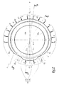
- the radial distance between this axis and the outer profile of the tab 14 has two maximum values, referenced R 14 at the figure 2 and respectively located at the two connection areas between the current portion 14 1 and the two end portions 14 2.
- the tab 14 has a plane of symmetry P, which passes through the axis XX, as clearly visible on the figure 2 .
- the skirt 12 is provided with an outer flange 16 which extends radially outwardly projecting from the face 12A, and only on a portion peripheral 12 2 of the skirt.
- the peripheral extent of the portion 12 2 is strictly greater than that of the portion 12 1 , while being however limited by the fact that these portions 12 1 and 12 2 must be distinct from each other along the periphery of the skirt 12.
- the portions 12 1 and 12 2 do not overlap and are separated from each other by two peripheral portions 12 3, which are respectively located on either side of the portions 12 1 and 12 2 following the periphery of the skirt and which, between the tab and the flange, are devoid of any element protruding from the face 12A.
- the portion 12 2 of the flange 16 must be extended over more than 180 °.
- the release of the portions 12 3 must be sufficient so that the user can easily distinguish visually the tab 14 and the flange 16 along the periphery of the skirt 12, so that each portion 12 3 is extended. at least 5 ° around the XX axis.
- the portion 12 2 extends over 290 ° while each portion 12 3 is extended over about 10 °, being further noted that, here, the plane P form a plane of symmetry for the collar 16.
- the flange 16 includes, according to the periphery of the skirt, on the one hand, a running portion 16 1 , whose outer profile, in cross section along the axis XX, is circular and centered on this axis, and, d ' on the other hand, two end portions 16 2 , whose outer profile, always in cross-section along the axis XX, is curved so as to connect the current portion 16 1 to the outer face 12A of the skirt 12 by progressively decreasing the radial extension projecting from the flange with respect to this face 12A.
- the current portion 16 1 constitutes the bulk of the flange 16, in the sense that this portion 16 1 runs over more than 180 ° about the axis XX, preferably about 200 ° as in the example shown in the figures .
- the circular outer profile of the portion 16 1 of the collar 16 has a radius R 16 equal to a molding clearance, at the radial distance R 14 associated with the tab 14.
- the parts of the skirt 12 which respectively connect the bottom wall 10 to the tab and to the flange have respective outer surfaces. 12A 1 and 12A 2 different: the surface 12A 2 corresponds to a cylindrical portion of circular base, centered on the axis XX, and is connected to the upper flat surface 10A of the bottom wall 10 angularly, generally at an angle right, as clearly visible in the right part of the Figures 3 and 4 while the surface 12A 1 corresponds to a portion of a truncated cone, centered on the axis XX and converging towards the bottom wall 10, thus connecting the tab 14 and the surface 10A more bluntly than the surface 12A 2 , as clearly visible in the left part of the figure 3 .
- skirt portion connecting the tab 14 to the bottom wall 10 is, in a way, beveled or chamfered by comparison with the skirt portion connecting the flange 16 to the bottom wall, allows clearing of the material and free space above the tab 14, which increases the visibility of the latter to the attention of the user.
- the blunt surface 12A 1 extends on either side of the portion 12 1 , along the outer periphery of the skirt 12, at the portions 12 3 to gradually connect to the cylindrical surface 12A 2 .
- the skirt In the upper part of the skirt 12, approximately at the same axial level as the tab 14, the skirt is internally provided with a clipping band 18 in the form of a bulge of material extending radially inward from the skirt wall.
- this clipping band 18 In longitudinal section of the stopper 1, this clipping band 18 has a convex surface 18A, which is connected to the bottom wall 10 forming a receiving recess 20 complementary to the edge 5 of the neck 2.
- the clipping of the cap consists of engaging the convex surface 18A with the lower end of the edge 5, the latter being then received in the recess 20 and the bottom wall 10 then being pressed against the rim 3, as shown in the right-hand part of the Figures 3 and 4 .
- the unclipping of the stopper consists in disengaging the strip 18 and the edge 5, in initiating this disengagement from the front side of the plug 1 and this by acting on the tab 14, in particular by applying to this tab a force F directed upwards and in a direction parallel to the axis XX or, more frequently, slightly inclined by compared to this axis, as indicated on the figure 3 .
- the latter does not run continuously over the entire inner periphery of the skirt 12, but is advantageously interrupted at least at the portions 12 3, as clearly visible in the left part of the figure 4 .
- the skirt 12 is adapted to separate into two distinct parts, namely an upper portion 12.1, integral with the bottom wall 10, and a lower portion 12.2 initially connected to the upper portion 12.1 by a weakening peripheral line 22 located axially in the current portion of the skirt and schematized in the figures by dashed lines.
- the skirt portion 12.1 is intended to be disengaged from the neck 2, so that this portion 12.1 externally carries the tab 14 and, internally, the clipping strip 18.
- the skirt portion 12.2 is, in turn, intended to remain around the neck 2.
- this portion 12.2 is provided internally with a pallet 24 extending radially inwardly projecting from the inner surface of the skirt 12, running over the entire periphery of the skirt. When the cap is assembled at the neck 2, this pallet 24 extends axially below the boss 6 and is adapted, when the cap is then raised for the first time, to abut axially against this boss.
- this line comprises a succession of peripheral slots, not shown in detail in the figures, which locally weaken the skirt 12 and which delimit between them bridges, obtained during the molding of the cap 1 or by cutouts in the cap. mold outlet.
- the weakening line 22 has a lower breaking strength at the skirt portion 12 1 than in the rest of the skirt along its periphery.
- this lower breaking strength is related to the fact that the wall thickness of the current portion of the skirt is reduced at the axial level of the line weakening 22, and only at the front of the skirt, especially in the skirt portion 12 1 .
- the weakening line 22 may not extend continuously over the entire periphery of the skirt 12 but, on the contrary, be interrupted on the rear side of the cap 1, in particular in a peripheral portion of the skirt diametrically opposed to the portion 12 1 . In this way, the rupture of the line 22 does not allow to completely disengage the skirt portion 12.1 relative to the skirt portion 12.2 and the collar 2, since a non-breakable material link remains then to connect the skirt portions 12.1 and 12.2, forming a tilting hinge between these skirt portions.
- the assembly of the stopper 1 at the container neck is carried out using a bottling head, not shown in the figures.
- a bottling head not shown in the figures.
- various types of heads may be used, in particular ball heads, vacuum-gripping heads, cone heads, gripper heads, and the like.
- these heads allow the gripping of the cap 1, by enclosing it externally peripherally: this head applies gripping forces T substantially radial to the axis XX, according to a gripping contour C of circular shape, centered on the central axis of the head, as indicated on the figure 2 .
- the head adjusts the size of its circular gripping contour C so that this contour has a radius equal to the radius R 16 , which amounts to making the contour C coincide with the circular external profile of the running part 16 1 of the collar 16.
- this flange portion 16 1 extends over more than 180 ° about the axis XX and, on the other hand, the tab 14 is written in full at inside a circle centered on the axis XX and radius R 16 , the gripping head and the skirt 12 are positioned coaxially, being centered on the axis XX.
- the tab 14 forms, at its two junction zones between its current portion 14 1 and its end portions 14 2 , two radial bearing zones. potentials for the gripping head, as indicated by the two forces T respectively applied to these two zones at the figure 2 . The quality of the grip of the plug 1 is improved.
- the gripping head Once the gripping head is thus seized coaxially with the plug 1, it engages in force on the neck 2 in the direction of the axis X-X, until clipping the band 18 with the edge 5.
Landscapes
- Engineering & Computer Science (AREA)
- Mechanical Engineering (AREA)
- Closures For Containers (AREA)
Claims (10)
- Verschluss (1) für einen Hals eines Behälters (2), eine rohrförmige Schürze (12) umfassend, die auf eine geometrische Achse (X-X) zentriert ist und geeignet ist, den Hals außen zu umschließen und die einerseits mit inneren Mitteln (18) zum Verrasten mit dem Hals, die ausgebildet sind, in lösbarer Weise den Verschluss auf dem Hals durch Klemmung mit einem Rand (5) des Halses zu befestigen, und andererseits mit einem äußeren Falz (14) zum manuellen Öffnen ausgestattet ist, der ermöglicht, den Verschluss in Bezug auf den Hals zu entrasten, und der sich von der Schürze herausragend nach außen erstreckt und nur über einen peripheren Bereich (121) der Schürze läuft,
dadurch gekennzeichnet, dass die Schürze (12) außerdem mit einem äußeren Kragen (16) versehen ist, der sich von der Schürze nach außen herausragend erstreckt und über einen peripheren Bereich (122) der Schürze umläuft, der unterschiedlich zu dem dem Falz (14) zugeordneten Bereich (121) ist und beidseitig davon gemäß dem Umfang der Schürze getrennt ist und von dem mindestens ein Teil (161), der über mehr als 180° um die Achse (X-X) umläuft, im Querschnitt zur Achse ein zentriert zur Achse kreisförmiges Außenprofil mit einem Radius (R16) im Wesentlichen gleich dem maximalen radialen Abstand (R14) zwischen der Achse und dem Außenprofil des Falzes aufweist. - Verschluss nach Anspruch 1, dadurch gekennzeichnet, dass der Teil (161) des Kragens (16) mit kreisförmigem Außenprofil sich über ungefähr 200° um die Achse (X-X) erstreckt.
- Verschluss nach einem der Ansprüche 1 oder 2, dadurch gekennzeichnet, dass der dem Kragen (16) zugeordnete Bereich (122) beidseitig gemäß dem Umfang der Schürze (12) von dem dem Falz (14) zugeordneten Bereich (121) durch einen Umfangsbereich (123) der Schürze getrennt ist, der sich über mindestens 5° um die Achse (X-X) erstreckt.
- Verschluss nach einem beliebigen der vorhergehenden Ansprüche, dadurch gekennzeichnet, dass der Falz (14) und der Kragen (16) eine selbe Symmetrieebene (P) definieren, die die Achse (X-X) enthält.
- Verschluss nach einem beliebigen der vorhergehenden Ansprüche, dadurch gekennzeichnet, dass der Falz (14) und der Kragen (16) auf einem selben axialen Niveau längs der Schürze (12) liegen.
- Verschluss nach einem beliebigen der Ansprüche 1 bis 4, dadurch gekennzeichnet, dass der Falz (14) und der Kragen (16) auf jeweils unterschledlichen Niveaus der Schürze (12) gemäß ihrer axialen Richtung (X-X) liegen.
- Verschluss nach einem beliebigen der vorhergehenden Ansprüche, dadurch gekennzeichnet, dass die Rastmittel einen Raststreifen (18) einschließen, der auf dem inneren Umfang der Schürze (12) umläuft, wobei er vorzugsweise, dem Umfang der Schürze folgend, zumindest zwischen dem dem Falz (14) zugeordneten Bereich (121) und dem dem Kragen (16) zugeordneten Bereich (122) unterbrochen ist.
- Verschluss nach einem beliebigen der vorhergehenden Ansprüche, dadurch gekennzeichnet, dass er außerdem eine Bodenwand (10) umfasst, die eines der axialen Enden der Schürze (12) verschließt, und dass der Teil der Schürze, der den Falz (14) mit der Bodenwand (10) verbindet, eine abgestumpftere Außenfläche (12A1) als die Außenfläche (12A2) des Teils der Schürze aufweist, der den Kragen (16) mit der Bodenwand verbindet,
- Verschluss nach einem beliebigen der vorhergehenden Ansprüche, dadurch gekennzeichnet, dass die Schürze (12) mit einer umfänglichen Schwächungslinie (22) versehen ist, die geeignet ist, bei dem ersten Öffnen des Verschlusses (1) zerbrochen zu werden, und beidseitig zu dieser gemäß der Richtung der Achse (X-X) die Schürze (12) einerseits einen lösbaren Teil (12.1), der außen mit dem Falz (14) und innen mit den Rastmitteln (18) versehen ist, und andererseits einen nicht lösbaren Teil (12.2) einschließt, der mit Haltemitteln (24) ausgerüstet ist, die geeignet sind, ihn um den Hals (2) zurückzuhalten, wenn der lösbare Teil der Schürze vom Hals gelöst ist,
und dass der Teil der Schwächungslinie (22), der in dem dem Falz (14) zugeordneten Bereich (121) gemäß dem Umfang der Schürze (12) liegt, einen Widerstand gegen das Zerbrechen aufweist, der geringer als der Rest der Schwächungslinie ist. - Verschluss nach einem beliebigen der vorhergehenden Ansprüche, dadurch gekennzeichnet, dass die Schürze (12) mit einer umfänglichen Schwächungslinie (22) versehen ist, die geeignet ist, bei dem ersten Öffnen des Verschlusses (1) zerbrochen zu werden, und beidseitig zu der gemäß der Richtung der Achse (X-X) die Schürze (12) einerseits einen lösbaren Teil (12,1), der außen mit dem Falz (14) und innen mit den Rastmitteln (18) versehen ist, und andererseits einen nicht lösbaren Teil (12.2) einschließt, der mit Haltemitteln (24) ausgestattet ist, die geeignet sind, ihn um den Hals (2) zurückzuhalten, wenn der lösbare Teil der Schürze von dem Hals getrennt ist,
und dass der lösbare (12.1) und nicht lösbare (12.2) Teil durch ein Band aus nicht zerbrechlichem Material verbunden sind, das gemäß dem Umfang der Schürze (12) entgegengesetzt zu dem dem Falz (14) zugeordneten Bereich (121) liegt und das ein Scharnier zum Schwenken zwischen dem lösbaren und nicht lösbaren Teil der Schürze bildet.
Priority Applications (1)
| Application Number | Priority Date | Filing Date | Title |
|---|---|---|---|
| PL09766049T PL2300331T3 (pl) | 2008-05-26 | 2009-05-25 | Korek zaciskany z wystającym wypustem do szyjki pojemnika |
Applications Claiming Priority (2)
| Application Number | Priority Date | Filing Date | Title |
|---|---|---|---|
| FR0853407A FR2931458B1 (fr) | 2008-05-26 | 2008-05-26 | Bouchon clipse a onglet saillant pour un col de recipient |
| PCT/FR2009/050957 WO2009153487A2 (fr) | 2008-05-26 | 2009-05-25 | Bouchon clipse a onglet saillant pour un col de recipient |
Publications (2)
| Publication Number | Publication Date |
|---|---|
| EP2300331A2 EP2300331A2 (de) | 2011-03-30 |
| EP2300331B1 true EP2300331B1 (de) | 2012-07-04 |
Family
ID=40225609
Family Applications (1)
| Application Number | Title | Priority Date | Filing Date |
|---|---|---|---|
| EP09766049A Active EP2300331B1 (de) | 2008-05-26 | 2009-05-25 | Anklemmbare kappe mit vorragender lasche für den hals eines behälters |
Country Status (9)
| Country | Link |
|---|---|
| US (1) | US8353414B2 (de) |
| EP (1) | EP2300331B1 (de) |
| CA (1) | CA2725291C (de) |
| ES (1) | ES2389164T3 (de) |
| FR (1) | FR2931458B1 (de) |
| MX (1) | MX2010012926A (de) |
| PL (1) | PL2300331T3 (de) |
| PT (1) | PT2300331E (de) |
| WO (1) | WO2009153487A2 (de) |
Families Citing this family (14)
| Publication number | Priority date | Publication date | Assignee | Title |
|---|---|---|---|---|
| US9340332B2 (en) | 2013-03-15 | 2016-05-17 | Sonoco Development, Inc. | Closure for container |
| CN104108527A (zh) * | 2014-05-28 | 2014-10-22 | 李红彪 | 一种可降低瓶盖高度的饮料瓶 |
| CN104210742B (zh) * | 2014-08-28 | 2016-09-14 | 航天精工股份有限公司 | 一种用于玻璃容量瓶口密封的盖子 |
| USD784808S1 (en) * | 2015-10-06 | 2017-04-25 | Betapack, S.A.U. | Bottle top |
| AU201713332S (en) * | 2017-06-02 | 2017-06-15 | Pact Group Holdings Nz Ltd | Lid for a container |
| EP3749585B1 (de) | 2017-12-15 | 2023-09-13 | Husky Injection Molding Systems Ltd. | Verschlusskappe für einen behälter |
| USD892614S1 (en) * | 2018-06-11 | 2020-08-11 | Ecolab Usa Inc. | Cap for container |
| USD933479S1 (en) * | 2019-07-09 | 2021-10-19 | Betapack, S.A.U. | Bottle cap |
| USD933478S1 (en) * | 2019-07-09 | 2021-10-19 | Betapack, S.A.U. | Bottle cap |
| USD1013512S1 (en) | 2019-10-10 | 2024-02-06 | Merrilee Kick | Container |
| WO2022163570A1 (ja) * | 2021-01-27 | 2022-08-04 | 株式会社ヤクルト本社 | 合成樹脂キャップ |
| US11738903B2 (en) | 2021-09-02 | 2023-08-29 | Merrilee Kick | Container apparatus |
| US11975889B2 (en) | 2021-09-02 | 2024-05-07 | Merrilee Kick | Container apparatus |
| US12606354B2 (en) | 2024-09-20 | 2026-04-21 | Phoenix Closures, Inc. | Child-resistant closure system |
Family Cites Families (8)
| Publication number | Priority date | Publication date | Assignee | Title |
|---|---|---|---|---|
| FR1206589A (fr) * | 1958-11-08 | 1960-02-10 | Jafax | Bouchon de bouteille |
| FR1484391A (fr) * | 1966-06-23 | 1967-06-09 | Dale Ltd John | Fermeture de récipient |
| GB1226245A (de) * | 1968-07-17 | 1971-03-24 | ||
| BE790574A (fr) * | 1971-10-26 | 1973-02-15 | Wiedmer Plastikform W | Fermeture pour recipients |
| US4429800A (en) * | 1982-06-01 | 1984-02-07 | Greenspan Donald J | Child safe container-closure unit |
| US4919286A (en) * | 1988-05-27 | 1990-04-24 | Robert Linkletter Assoc. | Hinged closure and container |
| US5423441A (en) * | 1993-12-20 | 1995-06-13 | American Safety Closure Corp. | Closure system for a container and cap |
| US5540349A (en) * | 1995-03-07 | 1996-07-30 | Bennett Industries, Inc. | Container closure with separable wall segments |
-
2008
- 2008-05-26 FR FR0853407A patent/FR2931458B1/fr not_active Expired - Fee Related
-
2009
- 2009-05-25 CA CA2725291A patent/CA2725291C/fr active Active
- 2009-05-25 ES ES09766049T patent/ES2389164T3/es active Active
- 2009-05-25 MX MX2010012926A patent/MX2010012926A/es active IP Right Grant
- 2009-05-25 EP EP09766049A patent/EP2300331B1/de active Active
- 2009-05-25 PT PT09766049T patent/PT2300331E/pt unknown
- 2009-05-25 PL PL09766049T patent/PL2300331T3/pl unknown
- 2009-05-25 WO PCT/FR2009/050957 patent/WO2009153487A2/fr not_active Ceased
- 2009-05-25 US US12/994,632 patent/US8353414B2/en not_active Expired - Fee Related
Also Published As
| Publication number | Publication date |
|---|---|
| PL2300331T3 (pl) | 2012-10-31 |
| WO2009153487A3 (fr) | 2010-02-11 |
| WO2009153487A2 (fr) | 2009-12-23 |
| CA2725291C (fr) | 2016-01-19 |
| FR2931458A1 (fr) | 2009-11-27 |
| FR2931458B1 (fr) | 2010-06-04 |
| MX2010012926A (es) | 2011-01-25 |
| PT2300331E (pt) | 2012-07-30 |
| US8353414B2 (en) | 2013-01-15 |
| ES2389164T3 (es) | 2012-10-23 |
| US20110068079A1 (en) | 2011-03-24 |
| CA2725291A1 (fr) | 2009-12-23 |
| EP2300331A2 (de) | 2011-03-30 |
Similar Documents
| Publication | Publication Date | Title |
|---|---|---|
| EP2300331B1 (de) | Anklemmbare kappe mit vorragender lasche für den hals eines behälters | |
| EP2331418B1 (de) | Verschluss mit einer geschnittenen schwächungslinie und verfahren zur herstellung des verschlusses | |
| EP2704961B3 (de) | Kappe für den hals eines behälters | |
| CA2704603C (fr) | Procede et machine de fabrication d'un bouchon pour un col de recipient, ainsi que bouchon tel qu'obtenu par ce procede | |
| CA2716299C (fr) | Dispositif de bouchage d'un col de recipient | |
| FR2474450A1 (fr) | Bouchon de recipient a partie annulaire cassable | |
| FR2976921A1 (fr) | Dispositif de bouchage d'un col de recipient | |
| FR2936782A1 (fr) | Dispositif de bouchage d'un col de recipient, recipient equipe d'un tel dispositif, et procede de bouchage d'un tel recipient | |
| EP2104634B1 (de) | Kappe für den hals eines behälters und verfahren zur herstellung einer solchen kappe | |
| FR2953202A1 (fr) | Bouchon avec ligne d'affaiblissement | |
| EP3288846B1 (de) | Stopfen für einen behälterhals | |
| EP1940692B1 (de) | Verschlussvorrichtung für einen behälterhals, behälter damit und herstellungsverfahren dafür | |
| EP4005945B1 (de) | Anordnung mit einem behälter und einer am behälter befestigten verschlussvorrichtung | |
| FR2890943A1 (fr) | Dispositif de bouchage d'un col de recipient, recipient equipe d'un tel dispositif et procede de fabrication d'un tel dispositif | |
| FR2988702A1 (fr) | Bouchon de fermeture du goulot d'un contenant | |
| FR2906228A1 (fr) | Bouchon clipe pour un col de recipient et procede de fabrication d'un tel bouchon | |
| FR2578813A1 (fr) | Element de bouchage inviolable en matiere plastique pour bouteilles et recipients analogues | |
| FR2897043A1 (fr) | Dispositif de bouchage d'un col de recipient et recipient equipe d'un tel dispositif | |
| FR3045017A1 (fr) | Bouchon pour un col de recipient, ainsi que procede de fabrication d'un tel bouchon |
Legal Events
| Date | Code | Title | Description |
|---|---|---|---|
| PUAI | Public reference made under article 153(3) epc to a published international application that has entered the european phase |
Free format text: ORIGINAL CODE: 0009012 |
|
| 17P | Request for examination filed |
Effective date: 20101117 |
|
| AK | Designated contracting states |
Kind code of ref document: A2 Designated state(s): AT BE BG CH CY CZ DE DK EE ES FI FR GB GR HR HU IE IS IT LI LT LU LV MC MK MT NL NO PL PT RO SE SI SK TR |
|
| AX | Request for extension of the european patent |
Extension state: AL BA RS |
|
| DAX | Request for extension of the european patent (deleted) | ||
| GRAP | Despatch of communication of intention to grant a patent |
Free format text: ORIGINAL CODE: EPIDOSNIGR1 |
|
| GRAS | Grant fee paid |
Free format text: ORIGINAL CODE: EPIDOSNIGR3 |
|
| GRAA | (expected) grant |
Free format text: ORIGINAL CODE: 0009210 |
|
| RAP1 | Party data changed (applicant data changed or rights of an application transferred) |
Owner name: TETRA LAVAL HOLDINGS & FINANCE S.A. |
|
| AK | Designated contracting states |
Kind code of ref document: B1 Designated state(s): AT BE BG CH CY CZ DE DK EE ES FI FR GB GR HR HU IE IS IT LI LT LU LV MC MK MT NL NO PL PT RO SE SI SK TR |
|
| REG | Reference to a national code |
Ref country code: GB Ref legal event code: FG4D Free format text: NOT ENGLISH |
|
| REG | Reference to a national code |
Ref country code: CH Ref legal event code: EP |
|
| REG | Reference to a national code |
Ref country code: AT Ref legal event code: REF Ref document number: 565069 Country of ref document: AT Kind code of ref document: T Effective date: 20120715 |
|
| REG | Reference to a national code |
Ref country code: PT Ref legal event code: SC4A Free format text: AVAILABILITY OF NATIONAL TRANSLATION Effective date: 20120724 |
|
| REG | Reference to a national code |
Ref country code: IE Ref legal event code: FG4D Free format text: LANGUAGE OF EP DOCUMENT: FRENCH |
|
| REG | Reference to a national code |
Ref country code: DE Ref legal event code: R096 Ref document number: 602009008085 Country of ref document: DE Effective date: 20120830 |
|
| REG | Reference to a national code |
Ref country code: ES Ref legal event code: FG2A Ref document number: 2389164 Country of ref document: ES Kind code of ref document: T3 Effective date: 20121023 |
|
| REG | Reference to a national code |
Ref country code: PL Ref legal event code: T3 |
|
| REG | Reference to a national code |
Ref country code: NL Ref legal event code: T3 |
|
| REG | Reference to a national code |
Ref country code: AT Ref legal event code: MK05 Ref document number: 565069 Country of ref document: AT Kind code of ref document: T Effective date: 20120704 |
|
| PG25 | Lapsed in a contracting state [announced via postgrant information from national office to epo] |
Ref country code: SI Free format text: LAPSE BECAUSE OF FAILURE TO SUBMIT A TRANSLATION OF THE DESCRIPTION OR TO PAY THE FEE WITHIN THE PRESCRIBED TIME-LIMIT Effective date: 20120704 |
|
| REG | Reference to a national code |
Ref country code: LT Ref legal event code: MG4D Effective date: 20120704 |
|
| PG25 | Lapsed in a contracting state [announced via postgrant information from national office to epo] |
Ref country code: NO Free format text: LAPSE BECAUSE OF FAILURE TO SUBMIT A TRANSLATION OF THE DESCRIPTION OR TO PAY THE FEE WITHIN THE PRESCRIBED TIME-LIMIT Effective date: 20121004 Ref country code: IS Free format text: LAPSE BECAUSE OF FAILURE TO SUBMIT A TRANSLATION OF THE DESCRIPTION OR TO PAY THE FEE WITHIN THE PRESCRIBED TIME-LIMIT Effective date: 20121104 Ref country code: FI Free format text: LAPSE BECAUSE OF FAILURE TO SUBMIT A TRANSLATION OF THE DESCRIPTION OR TO PAY THE FEE WITHIN THE PRESCRIBED TIME-LIMIT Effective date: 20120704 Ref country code: HR Free format text: LAPSE BECAUSE OF FAILURE TO SUBMIT A TRANSLATION OF THE DESCRIPTION OR TO PAY THE FEE WITHIN THE PRESCRIBED TIME-LIMIT Effective date: 20120704 Ref country code: LT Free format text: LAPSE BECAUSE OF FAILURE TO SUBMIT A TRANSLATION OF THE DESCRIPTION OR TO PAY THE FEE WITHIN THE PRESCRIBED TIME-LIMIT Effective date: 20120704 Ref country code: AT Free format text: LAPSE BECAUSE OF FAILURE TO SUBMIT A TRANSLATION OF THE DESCRIPTION OR TO PAY THE FEE WITHIN THE PRESCRIBED TIME-LIMIT Effective date: 20120704 Ref country code: CY Free format text: LAPSE BECAUSE OF FAILURE TO SUBMIT A TRANSLATION OF THE DESCRIPTION OR TO PAY THE FEE WITHIN THE PRESCRIBED TIME-LIMIT Effective date: 20120704 |
|
| PG25 | Lapsed in a contracting state [announced via postgrant information from national office to epo] |
Ref country code: GR Free format text: LAPSE BECAUSE OF FAILURE TO SUBMIT A TRANSLATION OF THE DESCRIPTION OR TO PAY THE FEE WITHIN THE PRESCRIBED TIME-LIMIT Effective date: 20121005 Ref country code: SE Free format text: LAPSE BECAUSE OF FAILURE TO SUBMIT A TRANSLATION OF THE DESCRIPTION OR TO PAY THE FEE WITHIN THE PRESCRIBED TIME-LIMIT Effective date: 20120704 Ref country code: LV Free format text: LAPSE BECAUSE OF FAILURE TO SUBMIT A TRANSLATION OF THE DESCRIPTION OR TO PAY THE FEE WITHIN THE PRESCRIBED TIME-LIMIT Effective date: 20120704 |
|
| PG25 | Lapsed in a contracting state [announced via postgrant information from national office to epo] |
Ref country code: RO Free format text: LAPSE BECAUSE OF FAILURE TO SUBMIT A TRANSLATION OF THE DESCRIPTION OR TO PAY THE FEE WITHIN THE PRESCRIBED TIME-LIMIT Effective date: 20120704 Ref country code: CZ Free format text: LAPSE BECAUSE OF FAILURE TO SUBMIT A TRANSLATION OF THE DESCRIPTION OR TO PAY THE FEE WITHIN THE PRESCRIBED TIME-LIMIT Effective date: 20120704 Ref country code: EE Free format text: LAPSE BECAUSE OF FAILURE TO SUBMIT A TRANSLATION OF THE DESCRIPTION OR TO PAY THE FEE WITHIN THE PRESCRIBED TIME-LIMIT Effective date: 20120704 Ref country code: DK Free format text: LAPSE BECAUSE OF FAILURE TO SUBMIT A TRANSLATION OF THE DESCRIPTION OR TO PAY THE FEE WITHIN THE PRESCRIBED TIME-LIMIT Effective date: 20120704 |
|
| PLBE | No opposition filed within time limit |
Free format text: ORIGINAL CODE: 0009261 |
|
| STAA | Information on the status of an ep patent application or granted ep patent |
Free format text: STATUS: NO OPPOSITION FILED WITHIN TIME LIMIT |
|
| PG25 | Lapsed in a contracting state [announced via postgrant information from national office to epo] |
Ref country code: SK Free format text: LAPSE BECAUSE OF FAILURE TO SUBMIT A TRANSLATION OF THE DESCRIPTION OR TO PAY THE FEE WITHIN THE PRESCRIBED TIME-LIMIT Effective date: 20120704 |
|
| 26N | No opposition filed |
Effective date: 20130405 |
|
| PG25 | Lapsed in a contracting state [announced via postgrant information from national office to epo] |
Ref country code: BG Free format text: LAPSE BECAUSE OF FAILURE TO SUBMIT A TRANSLATION OF THE DESCRIPTION OR TO PAY THE FEE WITHIN THE PRESCRIBED TIME-LIMIT Effective date: 20121004 |
|
| REG | Reference to a national code |
Ref country code: DE Ref legal event code: R097 Ref document number: 602009008085 Country of ref document: DE Effective date: 20130405 |
|
| BERE | Be: lapsed |
Owner name: TETRA LAVAL HOLDINGS & FINANCE S.A. Effective date: 20130531 |
|
| PG25 | Lapsed in a contracting state [announced via postgrant information from national office to epo] |
Ref country code: MC Free format text: LAPSE BECAUSE OF FAILURE TO SUBMIT A TRANSLATION OF THE DESCRIPTION OR TO PAY THE FEE WITHIN THE PRESCRIBED TIME-LIMIT Effective date: 20120704 |
|
| REG | Reference to a national code |
Ref country code: CH Ref legal event code: PL |
|
| GBPC | Gb: european patent ceased through non-payment of renewal fee |
Effective date: 20130525 |
|
| PG25 | Lapsed in a contracting state [announced via postgrant information from national office to epo] |
Ref country code: CH Free format text: LAPSE BECAUSE OF NON-PAYMENT OF DUE FEES Effective date: 20130531 Ref country code: LI Free format text: LAPSE BECAUSE OF NON-PAYMENT OF DUE FEES Effective date: 20130531 |
|
| REG | Reference to a national code |
Ref country code: IE Ref legal event code: MM4A |
|
| PG25 | Lapsed in a contracting state [announced via postgrant information from national office to epo] |
Ref country code: BE Free format text: LAPSE BECAUSE OF NON-PAYMENT OF DUE FEES Effective date: 20130531 |
|
| PG25 | Lapsed in a contracting state [announced via postgrant information from national office to epo] |
Ref country code: IE Free format text: LAPSE BECAUSE OF NON-PAYMENT OF DUE FEES Effective date: 20130525 Ref country code: GB Free format text: LAPSE BECAUSE OF NON-PAYMENT OF DUE FEES Effective date: 20130525 |
|
| PG25 | Lapsed in a contracting state [announced via postgrant information from national office to epo] |
Ref country code: MT Free format text: LAPSE BECAUSE OF FAILURE TO SUBMIT A TRANSLATION OF THE DESCRIPTION OR TO PAY THE FEE WITHIN THE PRESCRIBED TIME-LIMIT Effective date: 20120704 |
|
| PG25 | Lapsed in a contracting state [announced via postgrant information from national office to epo] |
Ref country code: TR Free format text: LAPSE BECAUSE OF FAILURE TO SUBMIT A TRANSLATION OF THE DESCRIPTION OR TO PAY THE FEE WITHIN THE PRESCRIBED TIME-LIMIT Effective date: 20120704 |
|
| PG25 | Lapsed in a contracting state [announced via postgrant information from national office to epo] |
Ref country code: LU Free format text: LAPSE BECAUSE OF NON-PAYMENT OF DUE FEES Effective date: 20130525 Ref country code: MK Free format text: LAPSE BECAUSE OF FAILURE TO SUBMIT A TRANSLATION OF THE DESCRIPTION OR TO PAY THE FEE WITHIN THE PRESCRIBED TIME-LIMIT Effective date: 20120704 Ref country code: HU Free format text: LAPSE BECAUSE OF FAILURE TO SUBMIT A TRANSLATION OF THE DESCRIPTION OR TO PAY THE FEE WITHIN THE PRESCRIBED TIME-LIMIT; INVALID AB INITIO Effective date: 20090525 |
|
| REG | Reference to a national code |
Ref country code: FR Ref legal event code: PLFP Year of fee payment: 8 |
|
| REG | Reference to a national code |
Ref country code: FR Ref legal event code: PLFP Year of fee payment: 9 |
|
| REG | Reference to a national code |
Ref country code: FR Ref legal event code: PLFP Year of fee payment: 10 |
|
| P01 | Opt-out of the competence of the unified patent court (upc) registered |
Effective date: 20230306 |
|
| PGFP | Annual fee paid to national office [announced via postgrant information from national office to epo] |
Ref country code: NL Payment date: 20230419 Year of fee payment: 15 |
|
| PGFP | Annual fee paid to national office [announced via postgrant information from national office to epo] |
Ref country code: PT Payment date: 20230420 Year of fee payment: 15 Ref country code: IT Payment date: 20230420 Year of fee payment: 15 Ref country code: FR Payment date: 20230420 Year of fee payment: 15 Ref country code: ES Payment date: 20230601 Year of fee payment: 15 Ref country code: DE Payment date: 20230419 Year of fee payment: 15 |
|
| PGFP | Annual fee paid to national office [announced via postgrant information from national office to epo] |
Ref country code: PL Payment date: 20230424 Year of fee payment: 15 |
|
| REG | Reference to a national code |
Ref country code: DE Ref legal event code: R119 Ref document number: 602009008085 Country of ref document: DE |
|
| PG25 | Lapsed in a contracting state [announced via postgrant information from national office to epo] |
Ref country code: PT Free format text: LAPSE BECAUSE OF NON-PAYMENT OF DUE FEES Effective date: 20241125 |
|
| PG25 | Lapsed in a contracting state [announced via postgrant information from national office to epo] |
Ref country code: PT Free format text: LAPSE BECAUSE OF NON-PAYMENT OF DUE FEES Effective date: 20241125 |
|
| REG | Reference to a national code |
Ref country code: NL Ref legal event code: MM Effective date: 20240601 |
|
| PG25 | Lapsed in a contracting state [announced via postgrant information from national office to epo] |
Ref country code: NL Free format text: LAPSE BECAUSE OF NON-PAYMENT OF DUE FEES Effective date: 20240601 |
|
| PG25 | Lapsed in a contracting state [announced via postgrant information from national office to epo] |
Ref country code: DE Free format text: LAPSE BECAUSE OF NON-PAYMENT OF DUE FEES Effective date: 20241203 |
|
| PG25 | Lapsed in a contracting state [announced via postgrant information from national office to epo] |
Ref country code: FR Free format text: LAPSE BECAUSE OF NON-PAYMENT OF DUE FEES Effective date: 20240531 |
|
| PG25 | Lapsed in a contracting state [announced via postgrant information from national office to epo] |
Ref country code: IT Free format text: LAPSE BECAUSE OF NON-PAYMENT OF DUE FEES Effective date: 20240525 |
|
| REG | Reference to a national code |
Ref country code: ES Ref legal event code: FD2A Effective date: 20250701 |
|
| PG25 | Lapsed in a contracting state [announced via postgrant information from national office to epo] |
Ref country code: ES Free format text: LAPSE BECAUSE OF NON-PAYMENT OF DUE FEES Effective date: 20240526 |