EP2300294B1 - Servomoteur reglable d'assistance au freinage - Google Patents
Servomoteur reglable d'assistance au freinage Download PDFInfo
- Publication number
- EP2300294B1 EP2300294B1 EP09797476.0A EP09797476A EP2300294B1 EP 2300294 B1 EP2300294 B1 EP 2300294B1 EP 09797476 A EP09797476 A EP 09797476A EP 2300294 B1 EP2300294 B1 EP 2300294B1
- Authority
- EP
- European Patent Office
- Prior art keywords
- braking
- actuator
- chamber
- pressure
- piston
- Prior art date
- Legal status (The legal status is an assumption and is not a legal conclusion. Google has not performed a legal analysis and makes no representation as to the accuracy of the status listed.)
- Active
Links
Images


Classifications
-
- B—PERFORMING OPERATIONS; TRANSPORTING
- B60—VEHICLES IN GENERAL
- B60T—VEHICLE BRAKE CONTROL SYSTEMS OR PARTS THEREOF; BRAKE CONTROL SYSTEMS OR PARTS THEREOF, IN GENERAL; ARRANGEMENT OF BRAKING ELEMENTS ON VEHICLES IN GENERAL; PORTABLE DEVICES FOR PREVENTING UNWANTED MOVEMENT OF VEHICLES; VEHICLE MODIFICATIONS TO FACILITATE COOLING OF BRAKES
- B60T13/00—Transmitting braking action from initiating means to ultimate brake actuator with power assistance or drive; Brake systems incorporating such transmitting means, e.g. air-pressure brake systems
- B60T13/74—Transmitting braking action from initiating means to ultimate brake actuator with power assistance or drive; Brake systems incorporating such transmitting means, e.g. air-pressure brake systems with electrical assistance or drive
- B60T13/745—Transmitting braking action from initiating means to ultimate brake actuator with power assistance or drive; Brake systems incorporating such transmitting means, e.g. air-pressure brake systems with electrical assistance or drive acting on a hydraulic system, e.g. a master cylinder
Definitions
- the present invention relates primarily to an adjustable servomotor, particularly with regard to the value of the jump, braking assistance.
- braking assistance servomotors exerting a force on a push rod of a master cylinder which is an increasing function of the force exerted by the driver on a control rod, via a brake pedal.
- the assist ratio between the input force exerted on the control rod and the output force of the booster exerted on the push rod is constant. It is usual to use several ranges of use with several assistance reports, a first assistance report for comfort braking and a second assistance report, higher than said first assistance report for brake applications. emergency.
- servomotors for braking assistance of known type, mention may be made, in a nonlimiting manner, of pneumatic servos for assistance with vacuum braking, pressurized braking assistance pneumatic servomotors, hydraulic servomotors for braking assistance (called hydroboost in English terminology) as described for example in FR 2727370 and 494961846 , the pneumatic brake booster servomotors with decoupling between the control rod and the push rod such as for example that described in the patent applications WO 2007 080106 and WO 2007080158 , as well as electric servomotors for braking assistance such as that described in the French patent application published under the number FR-2860474 .
- Braking assistance boosters are also known, which furthermore comprise braking control means independent of the force exerted by the driver on the brake pedal commonly called "active booster" in English terminology.
- active booster An example of such a pneumatic booster is described in the patent EP 0478 396 .
- Braking assist servomotors are also described in the documents DE 10 2006 030168 , WO 03/066405 and EP 0 716 969 .
- the assistance ratio is regulated by a reaction device, in particular an incompressible elastomer reaction disk or a small diameter piston on which the pressure of a rear cylinder master chamber is exerted.
- the servomotor constantly ensures a dynamic equilibrium between the action and the reaction, particularly at the relative position of the control means, typically a three-way valve in the frame. of a pneumatic servomotor.
- the actuator according to the present invention comprises means for creating a non-zero offset and / or a variation, on command, for example of a computer, between the equilibrium position of the reaction forces between the control means, typically a plunger and / or a control rod and servomotor force application means.
- the "target" value of the operating equilibrium of the actuator of the servomotor is modified.
- a target signal value delivered by a position sensor is defined by programming the computer or by choosing a coefficient in a program as a function of the braking characteristic or characteristics that it is desired to implement.
- the computer controls the actuator with a setpoint value so that it acts until, dynamically, dynamically, it reaches the previously defined and / or selected target value.
- the setpoint can be calculated as a function of torque, a force of a position or other.
- the actuator moves the servomotor elements until the sensor emits the selected setpoint).
- the actuator according to the present invention by acting on the value of the target signal of the actuator control loop of the servomotor to act on the equilibrium clearance, that is to say on the geometric jump S for obtain the function (emergency braking assistance type, multiple assist ratio braking, rolling mass variation compensation or other) and / or the desired braking characteristic (braking with "bite", soft and easy braking to be metered or otherwise) according to the conditions of use of the vehicle such as the speed during braking, the total mass in roll, the conditions of adhesion, or the behavior of the driver (such as for example the speed of application of the foot on the brake pedal, application force, ).
- the function emergency braking assistance type, multiple assist ratio braking, rolling mass variation compensation or other
- the desired braking characteristic braking with "bite", soft and easy braking to be metered or otherwise
- the invention also relates to such a device characterized in that the processor generates control instructions of the actuator so as to vary said shift between the equilibrium position of said first and second movable crews.
- the invention also relates to such a device characterized in that it further comprises a reaction device exerting a reaction force on said first moving element and in that the equilibrium position to which the offset between said first and second moving equipments is detected by the sensor, is a balance position of reaction force on said first moving element.
- Another subject of the invention is such a device, characterized in that said offset increases the jump relative to the jump at the position with no offset at the corresponding jump of the part that can be driven by the actuating member by the driver and the stress application element.
- the invention also relates to such a device characterized in that the actuator comprises an electric motor.
- the invention also relates to such a device characterized in that it comprises an assistance piston driven by the pressure of a hydraulic fluid prevailing in a thrust chamber.
- the invention also relates to such a device characterized in that it further comprises means for connecting, on command, means for generating pressure of a hydraulic fluid to a chamber of a master cylinder.
- the invention also relates to such a device characterized in that it further comprises means for hermetically isolating, on command, the variable volume chamber and the thrust chamber.
- the invention also relates to such a device characterized in that it further comprises sealing means, on command, a chamber of the master cylinder and the brake fluid reservoir.
- the invention also relates to such a device characterized in that the processor is able to develop instructions of the actuator so as to vary, during braking, said shift between the balance position of effort of reaction on said part capable of being driven by the actuating member and the position of the force application element of the actuator.
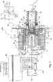
- a first embodiment according to the present invention comprising an envelope 2, a rotary electric motor 4 of axis X arranged inside the envelope which makes it possible to drive a ring 12.
- the motor is formed by a stationary electrical element called stator integral with the casing 2 and a rotatable electrical element called rotor 8 inside the stator.
- the stator is electrically powered for example by an alternator (not shown).
- the booster is attached to an apron 3 for separating an engine compartment from the passenger compartment of the motor vehicle.
- the rotor 8 forms a nut of a nut screw assembly, advantageously ball disposed within the envelope.
- the rotor is immobilized in translation and is rotatable about the longitudinal axis X, the rotor is held in the casing of the servomotor by means of a first and a second set of ball bearings, 7 and 9.
- the screw nut assembly 10 also comprises a screw formed by the annular ring 12 kept stationary in rotation with respect to the casing of the booster and able to move in translation relative to the rotor 8.
- the rotation of the rotor 8 drives in translation, the ring 12 by means of a first thread 14 carried by the inner wall of the rotor, the annular ring as for it is provided on its outer surface with a second thread 16 adapted to cooperate with the first thread 14.
- balls 18 are interposed between the outer wall of the ring 12 and the inner wall of the cylindrical sleeve forming a rotor.
- the servomotor according to the present invention also comprises an X-axis assist piston 20 mounted in the ring 12.
- the assistance piston comprises at a first rear end a piston tail 22 and at a second end before a base 24 supported by a rear face 26 against a front transverse face 28 of the annular ring 12.
- the assistance piston 20 is traversed by a longitudinal passage 30, in which is slidably mounted a plunger 32.
- the plunger 32 receives at a first rear end 34 a first front end 35 of a control rod 36 and is able to come into contact with a second front end with a first face 38 of a reaction disc 40 of elastically deformable material and incompressible such as an elastomer.
- the second leading end of the plunger 37 is also called a feeler.
- the control rod 36 is connected by a second rear longitudinal end to a brake pedal, which can be moved by a motor driver.
- the reaction disc 40 is disposed in a housing 42 formed in the front face of the assist piston so as to bear against a first face 38 against the assistance piston by a radially outer portion.
- the reaction disc is supported by a second face 44 against a first rear end 46 of a push rod 47, intended to transmit the driver's effort and the servomotor's assisting force to a master cylinder piston 49 48 by a second front end 50.
- the jump can be adjusted dynamically by the actuation, on command, of the engine 4.
- the position of a first movable element connected to the brake pedal 1, typically to the plunger 37 and / or the control rod 36, relative to the second movable element connected to the piston of the master cylinder 48, typically with respect to the push rod, relative to the drive piston to the reaction disc 40 is adjusted , dynamically, permanently, as well at rest as, if desired, during braking, by the action of the motor 4.
- the game or distance called geometric jump S in the remainder of this patent, between the probe 37 and a central portion of the rear face of the reaction disk 40 can be held stationary for a vehicle or a vehicle model, or it can vary from braking to another for the same vehicle or even during the same braking according to the characteristics of the desired braking.
- the servomotor also comprises means for fixing the plunger relative to the assistance piston, these means 52 are formed by a key substantially perpendicular to the axis X and fixedly mounted on the rear end 34 of the plunger and traversing with clearance in a transverse light made in the piston rod 22.
- the transverse ends 58 'of the key abut against the casing of the booster in the embodiment shown, the rear end of the casing has a shoulder 60 forming a support for an annular washer which forms a stop for the key 54.
- Sealing means are advantageously provided between the casing and the outer surface of the piston shank and between the casing and the control rod so as to prevent the entry of foreign particles likely to disturb the proper functioning of the booster. according to the present invention.
- the servomotor also comprises means 66 for detecting the relative displacement of the assistance piston and the plunger, this detection making it possible to control the actuation of the electric motor via a computer, and by the same means the displacement of the assistance piston.
- the means 66 are electrically connected to a calculator (ECU in English terminology) by a connector 65.
- the motor 4 receives the control signal from the computer via the link 100.
- the means 66 for detecting the relative displacement of the plunger assist piston comprise a resilient means interposed between the plunger and the assist piston and a force sensor 70, the elastic means 68 is supported by a first end against the plunger and a second end against the sensor 70.
- the first end of the resilient means 68 bears against a bottom of an axial annular groove of the plunger.
- the force sensor 70 is in turn in the example shown substantially annular shape, integral with the assistance piston and surrounding the front end of the plunger.
- the elastic means which in the example shown is formed by a cylindrical spring, is prestressed.
- the force sensor detects at rest a force applied by the cylindrical spring, this value of forces at rest forms for the computer a reference value V shown in point 11.
- the thread of the screw nut assembly is reversible, thus, the return of the assistance piston in the rest position is obtained without activation of the electric motor.
- a "reversible" thread is understood in the present application as a thread allowing the return of the screw in the rest position under the only actions of the pressure contained in the master cylinder and the return spring of the master pistons. -cylinder. It is not necessary to rotate the rotor in the opposite direction of the direction moving the ring towards the master cylinder, said direction of rise in pressure.
- An irreversible screw pitch is understood in the present application as requiring a rotation of the rotor in the direction opposite to the direction of rise in pressure to return the annular ring to the rest position.
- the computer 5 is not limited to servo tending to serve, in a closed loop, the value of the signal delivered by the connector 65 by the detection means 66 to a value V at rest at point 11 (typically V at rest is no).
- the computer 5 can, if necessary or useful, maintain, advantageously in a closed loop, a servocontrol of the motor 4 so that the signal, typically the voltage, delivered by the detection means 66 is a negative signal. 15.1, 15.2, ... corresponding, for example, to an increase in the jump or, on the contrary, controlled by positive voltage values such as 17.1 or 17.2.
- This slaving can be carried out by autonomous running programs of the computer 5 or, on the contrary, the execution of a program in response to a command 19 received by the computer 5, for example by means of a bus such as the CAN bus commonly used in the automotive industry.
- a control of the vehicle user interface such as a push button, a joystick or a selector input in a vehicle configuration menu allowing the driver to select the desired braking system behavior can also be connected to an input device, connected directly or not, for example to 19 to the computer 5.
- the present invention is not limited to electric servomotors braking assistance, but to any servomotor comprising an actuator 72 controlled by a control device advantageously a computer 5, a reaction device, typically a disc 40, means 66 for detecting position, or variation of position of the moving element connected to the brake pedal and a means for generating pressure, advantageously a master cylinder 48.
- a control device advantageously a computer 5
- a reaction device typically a disc 40
- a servomotor according to the present invention can be seen comprising a tandem master cylinder 48 equipped, in addition to a thrust chamber 76 receiving, on command, advantageously from a computer 5, a fluid, typically brake fluid under pressure.
- the effective surface of the thrust chamber 76 is adapted to the effective surface of the primary and / or secondary piston of the master cylinder 48.
- the effective area of the thrust chamber 76 is increased relative to that of the master cylinder chambers if it is desired to compensate for a low pressure (for example limited to 10 7 Pa) of the source of the brake fluid under pressure.
- a low pressure for example limited to 10 7 Pa
- such a ratio of surfaces may induce a movement of the brake pedal 1 during active modes.
- the saturation pressure that is to say the maximum pressure supplied by the high pressure source is equal to the pressure generated by the output assistance of the master cylinder.
- Pedal 1 remains stationary during active modes.
- the volume of fluid to be supplied to the chamber 76 for a given braking which limits the flow rate of the pump, to reduce the accumulator volume and / or improve the braking dynamics that is to say, to reduce the response time of the braking system.
- the booster according to the present invention comprises a hydraulic piston 78 whose rear face delimits the thrust chamber 76 and whose front face is arranged in a filled bore and with a compressible fluid typically of air advantageously vented through a pipe 80.
- a recess of the hydraulic piston 78 receives the reaction disc 40 on the front side of which rests a push rod 47.
- the rear face of the receiving housing of the reaction disc 40 has a shoulder ensuring the thrust of the corresponding section of the reaction disc by the hydraulic piston 78 and a central opening for receiving the anterior portion of the plunger 37, the surface ratio between said shoulder and said opening determines the default support report, in point 11, of the servomotor.
- the feed pressure generating means of the thrust chamber 76 comprise a master cylinder 82 having a variable volume chamber 84 in which the brake fluid pressure is increased by a driven piston 86, on command 100 by a motor 88, preferably an electric motor.
- the chamber 84 is an annular chamber connected by a pipe 90 to the thrust chamber 76.
- the engine is a stepper motor and drives the piston 86 via a screw balls.
- the piston 86 comprises at at least one of its axial ends, a hydraulic seal capable of withstanding the control pressures preferably as illustrated, a cup-type seal.
- the booster according to the present invention further comprises a solenoid valve 94 ensuring the hermetic closure, on command, of a pipe 96 connecting the chamber 84 to the master cylinder 48.
- the pipe 96 opens on the side the master cylinder 48 between two cups delimiting, in known manner, a re-feeding chamber of the master cylinder.
- This chamber is further connected to a reservoir 98 of brake fluid.
- the feed chamber is connected by openings in the primary piston to the primary chamber of the master cylinder 48. On the contrary, when the primary piston advances, the openings pass beyond the anterior cup allowing the pressure rise of the braking circuit.
- the solenoid valve 94 allows in case of failure of the engine 88 during braking to release the pressure of the chamber 84 in the tank 98 and thus to avoid in the event of a failure of the motor 88, undesired braking. Similarly, it should be noted that in the absence of assistance following a failure of the motor 88, a thrust on the control rod directly drives the push rod 47 without having to drive the motor 88.
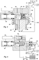
- figure 4 it is possible to see the preferred embodiment of the booster according to the present invention, which, in addition to the elements of the booster of the booster, figure 3 comprises a second solenoid valve 102 insulating, on command the thrust chamber 76 of the chamber 84 of the master cylinder 82.
- a second solenoid valve 102 insulating, on command the thrust chamber 76 of the chamber 84 of the master cylinder 82.
- the second solenoid valve 102 is particularly useful in the case of implementation of reversible screws, that is to say screws that can be rotated by a pressure variation in the motor chamber 76.
- the booster according to the present invention further comprises a third solenoid valve 103 isolating, on command, the primary chamber of the master cylinder 48 of the brake fluid reservoir 98. It is thus possible to ensure the pre-filling of the braking circuit through the master cylinder by opening the solenoid valve 94 by closing the valve 103 so as to prevent the pressure supplied to the primary chamber escapes to the tank. It should be noted that the pre-filling of the brakes is effected without advancement of the control rod 36, as a result of the brake pedal 1. Similarly, the combination of solenoid valves 94 open and solenoid valve 103 closed, allows to implement active braking modes that is to say on command of the computer 5, without the need for the action of the driver and, without moving the pedal 1. It should be noted that the secondary piston transmits to the chamber secondary pressure prevailing in the primary chamber, especially during active braking.
- the pre-filling of the brake can be very useful to reduce the braking distances and / or to allow the implementation of hydraulic brake with increased piston recoil which has a residual braking torque (undesired) zero and / or at least reduced .
- the solenoid valve 103 or any other hermetic isolation means on command, can be actuated to isolate at least one of the chambers of the master cylinder 48, typically the primary chamber so as, for example, to reduce the dead stroke at the moment the brake application, and preferably before the primary piston feed holes have passed the front cup of the primary chamber of the master cylinder or, if an abnormally high temperature has been detected during a braking operation that may result in in case of release of braking, the boiling of the brake fluid.
- the solenoid valve 103 is reopened so as to avoid undesired braking.
- the simulator comprises two hydraulic chambers connected by pipes, the assistance and braking devices being similar to those of the figure 3 .
- the electric motor 88 provides, on command, the advance of a piston 86 of a master cylinder, which is not necessarily annular, for supplying a brake fluid under pressure to a thrust chamber 76.
- the implementation of a simulator allows the price of an increase in the complexity of the system and its cost price, completely decouple the command set generated at the simulator of the pressure actually generated in the brake. This can be extremely useful in the case of a cooperation of several braking systems such as the regenerative braking system of hybrid vehicles comprising not only a heat engine but also an electric motor susceptible to braking, to act as a generator energy recovery.
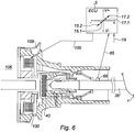
- the pneumatic booster of the figure 6 comprises, arranged in an envelope not shown, a front chamber 106 connected to the vacuum and a rear chamber 108 may be connected, on command of a three-way valve, at atmospheric pressure.
- the three-way valve can be controlled not only by the control rod 36 but also by an actuator 110 receiving a control signal 100 of the computer 5.
- the actuator is an electromagnet.
- FIG 7 an exemplary embodiment of a hydraulic servomotor according to the present invention can be seen having a hydraulic thrust chamber 76 fed with fluid under pressure by a vacuum pneumatic servomotor, the filling of the rear chamber 108 is provided by a solenoid valve 114 controlled by the computer 5.
- an exemplary embodiment of a servomotor according to the present invention can be seen comprising a thrust chamber 76 supplied, on command of the computer 5 by a pump 116 advantageously via a hydraulic circuit 118 comprising for example a valve and an accumulator. It is possible to use a dedicated pump 116, advantageously electric or on the contrary, to use a pump already present in the motor vehicle such as a pump of a hydraulic steering assistance device or a pump of a flight path control device called ESP in Anglo-Saxon terminology.
- the first mobile unit is provided with a magnet 120 arranged vis-à-vis a magnetic field detector 122, for example a Hall effect detector.
- the magnet 120 is an annular magnet and the detector 122 is a proportional detector.
- the axial displacement along the X axis ensures the variation of the magnetic field at the detector 122 and consequently the voltage 65 delivered by this detector.
- the arrangement of north and south poles of the magnet 120 is arranged axially along the axis X.
- the detector implemented in the device of the figure 1 and comprising a force sensor 70 compressed by a helical spring 68.
- the spring has a stiffness k constant so that the force F exerted by this spring on the sensor is proportional to the displacement of the plunger 32, a shoulder ensures compression of the spring.
- the detection means 66 comprising an elastic washer 128 carrying on its surface one or more strain gauges for example circumferential and / or radial 130.
- the washer 128 comprises anchoring means on a first mobile unit and drive means related to the second mobile unit.
- the washer 128 comprises peripheral means of inking on the moving element driven by the actuator of the booster according to the present invention.
- the periphery of the washer 128 is inked in a bore of the piston.
- the drive means of the radially inner edge of the washer 128 are advantageously carried by the plunger 32.
- the means 66 of the figure 11 detect the relative movement of the first movable element connected to the brake pedal relative to the second movable element driven by the actuator.
- the washer is illustrated deformed forward that is to say that the plunger has an advance on the piston.
- the jump value has been reduced in the position shown on the figure 11a , which corresponds to point 17i, (17.1, 17.2, 7) the voltage V delivered by the strain gauge being positive.
- the washer is deformed towards the rear, the strain gauge 130 delivering a signal 65 having a negative voltage corresponding to the point 15.i, (15.1, 15.2, ...) with advance of the piston on the plunger and increase of the jump .
- the control module of a servomotor according to the present invention can be seen in a neutral position in which the geometric jump S, that is to say the distance between the anterior face of the probe 32 and the rear face of the disc of Reaction measured along the X axis is determined by the geometry of the parts used.
- This is a neutral position in which the washer 128 is in the position illustrated on the figure 11b .
- a first section 134 at zero pressure corresponds to the attack force.
- a second substantially vertical section Sp corresponds to a rise in pressure at constant force at the beginning of braking.
- the pressure jump Sp is connected to an inclined rectilinear section whose slope corresponds to the assistance ratio of the servomotor.
- the section 136 is connected to a section 138 of lower slope corresponding to the saturation of the servomotor, that is to say that the servomotor provides the maximum force of which it is capable, the pressure increase resulting only from the increasing the force exerted via the brake pedal on the control rod 36.
- the actuator 72 typically the electric motor 4 can maintain the position of the figure 13a constant or on the contrary vary the shift in position of the two moving crews and therefore the direction and amplitude of the deformation of the washer 128.
- the configuration of the figure 13 can for example reduce the bite of braking both in normal use that for example when the vehicle carries a low mass or if a person wants fine-control braking or automatic braking smooth and / or soft for example when operating an automatic parking brake.
- FIG. figure 14c corresponds to a vertical Sp directly connecting a zero pressure to a saturation pressure without inclined segment 136.
- the signal value is illustrated in point 15.i.
- a control of the actuator 72 typically the engine 4 provides an emergency brake assist function (brake assist in English terminology).
- the three pressure curves P available at the output of the master cylinder can be seen as a function of the force F applied by the driver for possible use of the servomotor according to the present invention with, for example a control including compensation 100, emitted by the computer 5, the load of the vehicle.
- the curve 132.1 corresponds to a null or negligible jump corresponding to a position extending slightly beyond that illustrated on FIG. figure 13a .
- Curve 132.1 corresponds, for example, to the desired behavior obtained by the servomotor according to the present invention for a vehicle with a load less than the normal normal load of the vehicle, for example a case where the load of the vehicle is mainly constituted by the driver. himself.
- the curve 132.2 corresponds to the neutral position illustrated on the figure 12a .
- Curve 132.2 corresponds to a normally loaded vehicle.
- the curve 132.3 represents the case of an increased jump (but less than the jump illustrated on the figure 14a ).
- Curve 132.3 corresponds to a vehicle carrying a load greater than the normal load.
- the load carried by the vehicle, or more precisely the moving mass, is determined in a known manner, for example by a vehicle stabilization system, called ESP in the art and / or an accelerometer.
- ESP vehicle stabilization system
- the three curves comprise segments 136 parallel to each other and whose slope corresponds to the assistance ratio. It is interesting to compare these curves with the curve beams 138.1, 138.2 and 138.3 of the figure 16 which illustrates the deceleration y as a function of the force F.
- the curve 138.1 of the figure 16 corresponds to the case of curve 132.1 of the figure 15 .
- Curve 138.2 of the figure 16 corresponds to the curve 132.2 of the figure 15 .
- Curve 138.3 of the figure 16 corresponds to curve 132.3 of the figure 15 . It is found first of all that it is advantageous to obtain a jump in deceleration Sy which is constant for the three curves 138.
- the deceleration at the end of the jump is the same for the three curves.
- the slopes of the curves 138.1, 138.2 and 138.3 are increasing to intercept respectively 140.1, 140.2 and 140.3 saturation curves parallel to each other.
- the curve 140.3 is above the curve 140.2 itself above the curve 140.1.
- the deceleration saturation curves take into account the total force exerted both by the braking assistance servomotors and by the driver. We can see better on the figure 16 that the behavior and feeling of braking are completely different according to the relative positions of the two moving crews.
- the driver can be brought to a higher saturation curve (140.1) and consequently to a shorter stopping distance, and / or has a substantially constant stopping distance even for a transported load, that is to say a moving mass, greater.
- a beam of pressure curves P as a function of the force F has been illustrated for various system jump settings according to the present invention, for example a curve 132.1 optimizing braking for a hydraulic pressure of 2 10 6 Pa, a curve 132.2 optimizing a braking for a hydraulic pressure of 4 10 6 Pa, a curve 132.3 optimizing a braking for a hydraulic pressure of 4 10 6 Pa, a curve 132.4 optimizing a braking for a hydraulic pressure of 8 10 6 Pa, to arrive at a curve 132.5 corresponding for example to 10 7 Pa.
- a curve 132.1 optimizing braking for a hydraulic pressure of 2 10 6 Pa
- a curve 132.2 optimizing a braking for a hydraulic pressure of 4 10 6 Pa
- a curve 132.3 optimizing a braking for a hydraulic pressure of 4 10 6 Pa
- a curve 132.4 optimizing a braking for a hydraulic pressure of 8 10 6 Pa
- the changes in the shift between the moving crews may change during the same braking as the driver is pressing harder and harder on the brake and or depending on the pressure P and / or the deceleration therein. .
- the points corresponding to the pair of values (F, P) for the pressures of 2 10 6 Pa, 4 10 6 Pa, 6 10 6 Pa, 8 10 6 Pa and 10 7 Pa respectively bear the reference 144.1, 144.2, 144.3, 144.4 and 144.5.
- the line segment connecting said points 144.1 to 144.5 carries the references 146 and corresponds to the possible behavior of a braking system according to the present invention the judicious choice of the points 144.i (144.1, 144.2, ..., 144.5) allows, if desired, to obtain a behavior of the braking system that would be impossible to achieve with any device of known type. It is possible to increase and / or decrease an assistance ratio, linearly or otherwise, to describe a curve such as a sinusoidal type arc, a hyperbola or the like.
- the computer 5 can estimate the type of pedal sensation desired by the driver or drivers and adapt the pedal feel to the desired pedal feel.
- a servomotor comprising a hydraulic unit 146 comprising a pump 116 and a hydraulic control circuit 118 comprising for example a first solenoid valve 118.1 for evacuating the fluid from the thrust chamber 76 and a second solenoid valve 118.2 for supplying pressurized hydraulic fluid to said thrust chamber 76.
- the valves 118.1 and 118.2 are valves operating in all or nothing being controllable either continuously or, advantageously, by controlling the width of the valve. pulse (PWM in English terminology).
- the high pressure outlet of the pump 116 is connected to a battery 148 for stopping the pump 116 when its operation is not necessary.
- a pressure sensor 150 measures the available pressure at the outlet of the pump 116 / of the accumulator 148.
- the pressure sensor 150 is connected to a control device of a motor of the pump 116 as well as by a link 19 to the computer 5. It is understood that the implementation of other pressure sensors, for example at the primary and secondary braking circuit connected to the computer 5 and allowing pressure control, is not beyond the scope of the present invention.
- the pipe 80 is connected to the tank 98 so as to fill, at atmospheric pressure, the intermediate chamber between the chamber 76 and the primary chamber of the master cylinder.
- the various sealing elements typically the cups are bathed on their two opposite faces by brake fluid.
- the device of the figure 19 operates in a manner similar to the device of the figure 8 .
- hermetic unit 146 already available at a level of a trajectory control device (ESP) on a modern vehicle makes it possible to implement the device according to the present invention with a moderate additional cost.
- ESP trajectory control device
- the low pressure inlet of the pump 116 is connected by a pipe 152 to the reservoir 98.
- Each of the chambers of the tandem master cylinder 48 is connected to said reservoir 98 via a pipe.
- the hydraulic control circuit 118 further comprises a third solenoid valve 118.3 connecting, on command, a source of pressure, directly or indirectly to the primary chamber of the master cylinder 48.
- the sensor 66 delivers a corresponding signal 65 to the computer 5.
- the computer 5 generates a variation instruction of the brake assist.
- the solenoid valve 118.2 is open until the pressure in the thrust chamber 76 displaces the hydraulic piston 78 until the sensor 66 delivers a signal 65 corresponding to the desired shift between the first and second mobile crews.
- the valve 118.2 ensures the hermetic isolation of the high-pressure stage of the hydraulic unit 146.
- the valve 118.1 connected to the low pressure stage of the hydraulic unit 146 is closed.
- the computer 5 closes the valve 118.2 and the opening of the valve 118.1 until the pressure in the thrust chamber 76 ensures a shift between the first and second mobile teams corresponding to the value of desired record.
- the solenoid valve 118.1 is opened so as to ensure that the atmospheric pressure prevails in the thrust chamber 76 while the solenoid valve 118.2 is closed.
- the hydraulic unit 146 further comprises a second pressure sensor 152 measuring the pressure delivered to the thrust chamber 76.
- the effective section of the thrust chamber 76 is equal to the effective cross section of the primary piston and / or the secondary piston of the master cylinder 48.
- the valve 118.3 connects, on control 100 the high pressure stage of the hydraulic unit 146 to the primary chamber of the master cylinder 48.
- the opening of the valve 118.3, on order 100 of the computer 5 ensures the pre-filling and / or filling of the primary chamber of the master cylinder 48 allowing the operation of the active modes, that is to say without requiring the support on the pedal 1 of the braking system, for example for automatic braking on command of a radar (ACC), parking braking or other.
- ACC radar
- the increase in the pressure in the primary chamber of the master cylinder 48 pushes the secondary piston which in turn ensures the increase in pressure in the secondary circuit.
- the equal or almost equal cross sections of the primary piston and the thrust chamber 76 can supply high pressure brake fluid brakes without depressing the pedal 1 without the need to resort to a simulator (contrary to the case illustrated on the figure 16 ).
- the absence of connection between the primary chamber of the master cylinder 48 and the reservoir 98 allows with a single valve 118.3 (without the need for a valve 103) to ensure the active mode and / or the pre-filling of the brakes.
- the invention applies in particular to the automotive industry.
Landscapes
- Engineering & Computer Science (AREA)
- Transportation (AREA)
- Mechanical Engineering (AREA)
- Braking Systems And Boosters (AREA)
- Regulating Braking Force (AREA)
Priority Applications (1)
| Application Number | Priority Date | Filing Date | Title |
|---|---|---|---|
| PL09797476T PL2300294T3 (pl) | 2008-07-17 | 2009-07-10 | Regulowany siłownik do wspomagania hamowania |
Applications Claiming Priority (2)
| Application Number | Priority Date | Filing Date | Title |
|---|---|---|---|
| FR0804079A FR2933936B1 (fr) | 2008-07-17 | 2008-07-17 | Servomoteur reglable d'assistance au freinage |
| PCT/EP2009/058809 WO2010006996A1 (fr) | 2008-07-17 | 2009-07-10 | Servomoteur reglable d'assistance au freinage |
Publications (2)
| Publication Number | Publication Date |
|---|---|
| EP2300294A1 EP2300294A1 (fr) | 2011-03-30 |
| EP2300294B1 true EP2300294B1 (fr) | 2019-10-30 |
Family
ID=40566388
Family Applications (1)
| Application Number | Title | Priority Date | Filing Date |
|---|---|---|---|
| EP09797476.0A Active EP2300294B1 (fr) | 2008-07-17 | 2009-07-10 | Servomoteur reglable d'assistance au freinage |
Country Status (6)
| Country | Link |
|---|---|
| US (1) | US8874343B2 (pl) |
| EP (1) | EP2300294B1 (pl) |
| CN (1) | CN102046441B (pl) |
| FR (1) | FR2933936B1 (pl) |
| PL (1) | PL2300294T3 (pl) |
| WO (1) | WO2010006996A1 (pl) |
Families Citing this family (47)
| Publication number | Priority date | Publication date | Assignee | Title |
|---|---|---|---|---|
| DE102009026966A1 (de) * | 2008-12-18 | 2010-07-01 | Robert Bosch Gmbh | Betrieb eines Bremskraftverstärkers als Pedalsimulator |
| EP2535234A4 (en) * | 2010-02-12 | 2015-05-20 | Bosch Corp | ELECTRICAL SERVICE DEVICE AND BRAKING DEVICE THEREFOR |
| DE102010001939B4 (de) * | 2010-02-15 | 2012-05-16 | Robert Bosch Gmbh | Bremskraftverstärker sowie Verfahren und Vorrichtung zu dessen Betrieb |
| FR2958903B1 (fr) | 2010-04-14 | 2012-08-17 | Bosch Gmbh Robert | Ensemble hydraulique de freinage d'un vehicule comprenant un capteur de niveau de fluide hydraulique. |
| DE102010038918A1 (de) * | 2010-05-20 | 2011-11-24 | Robert Bosch Gmbh | Bremskraftverstärker sowie Verfahren zu dessen Betrieb |
| WO2012034661A1 (de) | 2010-09-17 | 2012-03-22 | Ipgate Ag | Betätigungsvorrichtung für eine kraftfahrzeug-bremsanlage |
| DE102010043203B4 (de) * | 2010-11-02 | 2024-02-01 | Robert Bosch Gmbh | Bremskraftverstärker und Verfahren zum Betrieb eines Bremskraftverstärkers |
| DE102010043202A1 (de) * | 2010-11-02 | 2012-05-03 | Robert Bosch Gmbh | Bremskraftverstärker und Verfahren zum Betrieb eines Bremskraftverstärkers |
| FR2968260B1 (fr) * | 2010-12-01 | 2016-03-11 | Bosch Gmbh Robert | Ensemble hydraulique de freinage d'un vehicule et reduction de la course morte dudit vehicule |
| FR2969092B1 (fr) | 2010-12-15 | 2012-12-28 | Bosch Gmbh Robert | Dispositif d'assistance au freinage et vehicule automobile comportant un tel dispositif |
| FR2970454B1 (fr) * | 2011-01-19 | 2013-02-15 | Peugeot Citroen Automobiles Sa | Amplificateur de freinage, en particulier pour un vehicule automobile |
| KR101767880B1 (ko) * | 2011-04-19 | 2017-08-16 | 현대모비스 주식회사 | 자동차용 제동장치 |
| US8496302B2 (en) | 2011-09-23 | 2013-07-30 | Robert Bosch Gmbh | Brake booster |
| US8777331B2 (en) | 2011-09-23 | 2014-07-15 | Robert Bosch Gmbh | Brake booster |
| US8641152B2 (en) * | 2011-11-07 | 2014-02-04 | Ford Global Technologies, Llc | Method and system for brake control |
| DE102012205432B4 (de) * | 2012-04-03 | 2025-11-27 | Robert Bosch Gmbh | Bremsbetätigungs-Sensorvorrichtung für ein Bremssystem eines Fahrzeugs und Verfahren zum Montieren einer Bremsbetätigungs-Sensorvorrichtung an einem Bremssystem eines Fahrzeugs |
| DE102012211278A1 (de) | 2012-06-29 | 2014-01-02 | Robert Bosch Gmbh | Verfahren zum Betreiben eines rekuperativen Bremssystems eines Fahrzeugs, Steuervorrichtung für ein rekuperatives Bremssystem eines Fahrzeugs und rekuperatives Bremssystem |
| CN103802813B (zh) * | 2012-11-12 | 2018-11-06 | 博世汽车部件(苏州)有限公司 | 助力器及制动系统 |
| KR101975174B1 (ko) * | 2012-11-28 | 2019-05-07 | 현대모비스 주식회사 | 전동부스터 방식 제동장치의 하중 지지 구조 |
| DE102012025292A1 (de) * | 2012-12-21 | 2014-06-26 | Lucas Automotive Gmbh | Verfahren und Baugruppe zur Bremskraftverstärkung für eine elektrohydraulische Kraftfahrzeug-Bremsanlage |
| DE102012025249B4 (de) * | 2012-12-21 | 2025-01-23 | Zf Active Safety Gmbh | Elektrohydraulische Fahrzeug-Bremsanlage und Verfahren zum Betreiben derselben |
| US9260091B2 (en) | 2013-07-16 | 2016-02-16 | Ford Global Technologies, Llc | Method and system for reducing vacuum consumption in a vehicle |
| US9145118B2 (en) | 2013-07-16 | 2015-09-29 | Ford Global Technologies, Llc | Method and system for reducing vacuum use in a vehicle |
| DE102013214339A1 (de) * | 2013-07-23 | 2015-01-29 | Robert Bosch Gmbh | Steuervorrichtung für einen regelbaren Bremskraftverstärker eines Bremssystems und Verfahren zum Betreiben eines regelbaren Bremskraftverstärkers eines Bremssystems |
| DE102014202159A1 (de) * | 2014-02-06 | 2015-08-06 | Robert Bosch Gmbh | Verfahren zum Bereitstellen einer durch eine automatische Parkbremse erzeugten Klemmkraft |
| CN104973038A (zh) * | 2014-04-10 | 2015-10-14 | 上海通用汽车有限公司 | 车用电控机械式助力系统及控制方法和车辆 |
| US10099662B2 (en) | 2015-03-11 | 2018-10-16 | Ford Global Technologies, Llc | Braking systems including compressible medium to modify brake fluid pressure |
| US10780865B2 (en) * | 2015-05-29 | 2020-09-22 | Hitachi Automotive Systems, Ltd. | Electric booster and stroke detector |
| DE102015217905A1 (de) * | 2015-09-18 | 2017-03-23 | Volkswagen Aktiengesellschaft | Automatische Adaption der Bremskraftverstärkung an unterschiedliche Bremslasten |
| KR102495106B1 (ko) * | 2016-01-26 | 2023-02-03 | 에이치엘만도 주식회사 | 전자식 브레이크 시스템 |
| DE102016208348A1 (de) | 2016-05-13 | 2017-11-16 | Continental Teves Ag & Co. Ohg | Bremsgerät für eine hydraulische Kraftfahrzeugbremsanlage mit einem Kugelgewindetrieb |
| DE102016210605A1 (de) | 2016-06-15 | 2017-12-21 | Robert Bosch Gmbh | Auswerte- und/oder Steuervorrichtung und Verfahren zum Ermitteln einer Information bezüglich einer mechanisch wirksamen Leistung eines aktiven Bremskraftverstärkers |
| JP2020055324A (ja) * | 2017-01-26 | 2020-04-09 | 日立オートモティブシステムズ株式会社 | 電動ブレーキ装置 |
| CN107139911A (zh) * | 2017-04-24 | 2017-09-08 | 浙江零跑科技有限公司 | 一种智能化制动主缸 |
| FR3072348B1 (fr) | 2017-10-18 | 2019-11-08 | Robert Bosch Gmbh | Module hydraulique de servofrein electrohydraulique integre |
| JP2019211362A (ja) * | 2018-06-06 | 2019-12-12 | ロベルト・ボッシュ・ゲゼルシャフト・ミト・ベシュレンクテル・ハフツングRobert Bosch Gmbh | 圧力センサモジュール |
| CN108860117A (zh) * | 2018-06-14 | 2018-11-23 | 天津英创汇智汽车技术有限公司 | 制动控制方法、制动系统及计算机可读介质 |
| DE102018211549A1 (de) | 2018-07-11 | 2020-01-16 | Robert Bosch Gmbh | Elektromechanischer Bremskraftverstärker und Herstellungsverfahren für einen elektromechanischen Bremskraftverstärker |
| CN109435931B (zh) * | 2018-12-13 | 2019-05-28 | 吉林大学 | 一种主动切换驾驶风格的集成式电子液压制动系统 |
| DE112020002307T5 (de) | 2019-05-09 | 2022-02-17 | Cts Corporation | Fahrzeugbremspedal mit pedalwiderstandsbaugruppe und kraft-/positionssensor |
| JP7068245B2 (ja) * | 2019-08-22 | 2022-05-16 | トヨタ自動車株式会社 | ブレーキマスタシリンダユニットの取り付け構造 |
| US11548625B2 (en) * | 2019-12-13 | 2023-01-10 | Goodrich Corporation | Aircraft brake system |
| CN116917172A (zh) | 2021-01-13 | 2023-10-20 | Cts公司 | 车辆踏板阻力阻尼组件 |
| KR102907231B1 (ko) * | 2021-01-25 | 2025-12-31 | 현대모비스 주식회사 | 회생제동 및 유압제동을 수행하는 차량의 브레이크 시스템 및 그 제어방법 |
| CN118076521A (zh) | 2021-10-11 | 2024-05-24 | Cts公司 | 带位置传感器的车辆踏板弹簧阻尼模拟器组件 |
| US12090980B2 (en) | 2022-09-06 | 2024-09-17 | Cts Corporation | Brake pedal emulator |
| US20250091560A1 (en) * | 2023-09-19 | 2025-03-20 | Robert Bosch Gmbh | Hydraulic boost failure compensation system |
Family Cites Families (9)
| Publication number | Priority date | Publication date | Assignee | Title |
|---|---|---|---|---|
| FR2667368B1 (fr) * | 1990-09-28 | 1994-10-21 | Bendix Europ Services Tech | Servomoteur a depression. |
| FR2727370A1 (fr) | 1994-11-29 | 1996-05-31 | Alliedsignal Europ Services | Systeme de freinage hydraulique assiste |
| US5558409A (en) * | 1994-12-14 | 1996-09-24 | General Motors Corporation | Electrohydraulic braking system |
| EP1474321B1 (de) * | 2002-02-07 | 2008-08-20 | Continental Teves AG & Co. oHG | Verfahren zur ermittlung oder kalibrierung der aussteuerungskennlinie eines unterdruckbremskraftverstärkers |
| FR2860474B1 (fr) * | 2003-10-02 | 2006-04-28 | Bosch Gmbh Robert | Servomoteur electrique d'assistance au freinage et vehicule comportant un tel servomoteur |
| US7367187B2 (en) * | 2005-06-30 | 2008-05-06 | Hitachi, Ltd. | Electrically actuated brake booster |
| JP4784756B2 (ja) * | 2005-09-26 | 2011-10-05 | 日立オートモティブシステムズ株式会社 | 電動倍力装置 |
| EP1976738B1 (fr) | 2006-01-10 | 2016-08-17 | Robert Bosch Gmbh | Systeme de commande de freinage comportant un simulateur de commande en pression |
| US8186772B2 (en) * | 2007-03-30 | 2012-05-29 | Nissin Kogyo Co., Ltd. | Vehicle brake apparatus |
-
2008
- 2008-07-17 FR FR0804079A patent/FR2933936B1/fr not_active Expired - Fee Related
-
2009
- 2009-07-10 WO PCT/EP2009/058809 patent/WO2010006996A1/fr not_active Ceased
- 2009-07-10 PL PL09797476T patent/PL2300294T3/pl unknown
- 2009-07-10 US US13/054,708 patent/US8874343B2/en active Active
- 2009-07-10 CN CN200980119013.8A patent/CN102046441B/zh active Active
- 2009-07-10 EP EP09797476.0A patent/EP2300294B1/fr active Active
Non-Patent Citations (1)
| Title |
|---|
| None * |
Also Published As
| Publication number | Publication date |
|---|---|
| PL2300294T3 (pl) | 2020-05-18 |
| CN102046441B (zh) | 2017-07-28 |
| CN102046441A (zh) | 2011-05-04 |
| FR2933936B1 (fr) | 2014-10-10 |
| FR2933936A1 (fr) | 2010-01-22 |
| US20110178687A1 (en) | 2011-07-21 |
| WO2010006996A1 (fr) | 2010-01-21 |
| EP2300294A1 (fr) | 2011-03-30 |
| US8874343B2 (en) | 2014-10-28 |
Similar Documents
| Publication | Publication Date | Title |
|---|---|---|
| EP2300294B1 (fr) | Servomoteur reglable d'assistance au freinage | |
| EP2300290B1 (fr) | Maître-cylindre comportant des moyens d'injection de liquide de frein dans ledit maître-cylindre et un systeme de freinage comportant un tel maître-cylindre | |
| EP2303656B1 (fr) | Servomoteur hydraulique d'assistance au freinage comportant un moteur | |
| EP1358098B1 (fr) | Installation de freinage hydraulique pour vehicule comportant un simulateur actif. | |
| EP2651734B1 (fr) | Dispositif d'assistance au freinage et vehicule automobile comportant un tel dispositif | |
| FR2975957A1 (fr) | Dispositif d'actionnement pour une installation de freinage de vehicule | |
| FR2860474A1 (fr) | Servomoteur electrique d'assistance au freinage et vehicule comportant un tel servomoteur | |
| FR2918332A1 (fr) | Systeme de commande pour systeme de freinage hydraulique | |
| FR2618112A1 (fr) | Systeme anti-blocage pour vehicule automobile | |
| FR3005294A1 (fr) | Servofrein electrohydraulique | |
| EP0912382A1 (fr) | Dispositif de freinage assiste a rapport d'assistance variable | |
| EP0939713B1 (fr) | Dispositif de freinage assiste a rapport d'assistance variable et hysteresis reduite | |
| FR2895958A1 (fr) | Systeme de commande de freinage comportant un simulateur de commande en pression | |
| EP2199161A1 (fr) | Système de simulation de sensation de freinage et véhicule comportant un tel système | |
| JP4491827B2 (ja) | 車両用ブレーキ装置 | |
| EP0915791A1 (fr) | Dispositif de freinage assiste a reaction hydraulique et securite accrue | |
| FR2970454A1 (fr) | Amplificateur de freinage, en particulier pour un vehicule automobile | |
| EP2646300B1 (fr) | Ensemble hydraulique de freinage d'un véhicule et réduction de la course morte dudit véhicule | |
| EP2127979A1 (fr) | Système de freinage pour le contrôle de stabilité et de trajectoire d'un véhicule automobile et procédés d'utilisation d'un tel système | |
| EP1053155B1 (fr) | Servomoteur pneumatique a reaction mecanique dynamiquement variable | |
| EP0939715A1 (fr) | Systeme de feinage assiste a reaction hydraulique amelioree | |
| JP6307950B2 (ja) | 車両用制動装置 | |
| FR2746154A1 (fr) | Frein a commande hydropneumatique | |
| FR2772709A1 (fr) | Systeme de freinage | |
| WO2017109054A1 (fr) | Frein de vehicule comprenant une mesure de l'effort de freinage, et procedes de commande |
Legal Events
| Date | Code | Title | Description |
|---|---|---|---|
| PUAI | Public reference made under article 153(3) epc to a published international application that has entered the european phase |
Free format text: ORIGINAL CODE: 0009012 |
|
| 17P | Request for examination filed |
Effective date: 20110217 |
|
| AK | Designated contracting states |
Kind code of ref document: A1 Designated state(s): AT BE BG CH CY CZ DE DK EE ES FI FR GB GR HR HU IE IS IT LI LT LU LV MC MK MT NL NO PL PT RO SE SI SK SM TR |
|
| AX | Request for extension of the european patent |
Extension state: AL BA RS |
|
| DAX | Request for extension of the european patent (deleted) | ||
| GRAP | Despatch of communication of intention to grant a patent |
Free format text: ORIGINAL CODE: EPIDOSNIGR1 |
|
| STAA | Information on the status of an ep patent application or granted ep patent |
Free format text: STATUS: GRANT OF PATENT IS INTENDED |
|
| INTG | Intention to grant announced |
Effective date: 20190521 |
|
| GRAS | Grant fee paid |
Free format text: ORIGINAL CODE: EPIDOSNIGR3 |
|
| GRAA | (expected) grant |
Free format text: ORIGINAL CODE: 0009210 |
|
| STAA | Information on the status of an ep patent application or granted ep patent |
Free format text: STATUS: THE PATENT HAS BEEN GRANTED |
|
| AK | Designated contracting states |
Kind code of ref document: B1 Designated state(s): AT BE BG CH CY CZ DE DK EE ES FI FR GB GR HR HU IE IS IT LI LT LU LV MC MK MT NL NO PL PT RO SE SI SK SM TR |
|
| REG | Reference to a national code |
Ref country code: GB Ref legal event code: FG4D Free format text: NOT ENGLISH |
|
| REG | Reference to a national code |
Ref country code: CH Ref legal event code: EP |
|
| REG | Reference to a national code |
Ref country code: AT Ref legal event code: REF Ref document number: 1195803 Country of ref document: AT Kind code of ref document: T Effective date: 20191115 |
|
| REG | Reference to a national code |
Ref country code: DE Ref legal event code: R096 Ref document number: 602009060299 Country of ref document: DE |
|
| REG | Reference to a national code |
Ref country code: IE Ref legal event code: FG4D Free format text: LANGUAGE OF EP DOCUMENT: FRENCH |
|
| REG | Reference to a national code |
Ref country code: LT Ref legal event code: MG4D |
|
| RAP2 | Party data changed (patent owner data changed or rights of a patent transferred) |
Owner name: ROBERT BOSCH GMBH |
|
| PG25 | Lapsed in a contracting state [announced via postgrant information from national office to epo] |
Ref country code: PT Free format text: LAPSE BECAUSE OF FAILURE TO SUBMIT A TRANSLATION OF THE DESCRIPTION OR TO PAY THE FEE WITHIN THE PRESCRIBED TIME-LIMIT Effective date: 20200302 Ref country code: ES Free format text: LAPSE BECAUSE OF FAILURE TO SUBMIT A TRANSLATION OF THE DESCRIPTION OR TO PAY THE FEE WITHIN THE PRESCRIBED TIME-LIMIT Effective date: 20191030 Ref country code: LT Free format text: LAPSE BECAUSE OF FAILURE TO SUBMIT A TRANSLATION OF THE DESCRIPTION OR TO PAY THE FEE WITHIN THE PRESCRIBED TIME-LIMIT Effective date: 20191030 Ref country code: FI Free format text: LAPSE BECAUSE OF FAILURE TO SUBMIT A TRANSLATION OF THE DESCRIPTION OR TO PAY THE FEE WITHIN THE PRESCRIBED TIME-LIMIT Effective date: 20191030 Ref country code: BG Free format text: LAPSE BECAUSE OF FAILURE TO SUBMIT A TRANSLATION OF THE DESCRIPTION OR TO PAY THE FEE WITHIN THE PRESCRIBED TIME-LIMIT Effective date: 20200130 Ref country code: NL Free format text: LAPSE BECAUSE OF FAILURE TO SUBMIT A TRANSLATION OF THE DESCRIPTION OR TO PAY THE FEE WITHIN THE PRESCRIBED TIME-LIMIT Effective date: 20191030 Ref country code: LV Free format text: LAPSE BECAUSE OF FAILURE TO SUBMIT A TRANSLATION OF THE DESCRIPTION OR TO PAY THE FEE WITHIN THE PRESCRIBED TIME-LIMIT Effective date: 20191030 Ref country code: SE Free format text: LAPSE BECAUSE OF FAILURE TO SUBMIT A TRANSLATION OF THE DESCRIPTION OR TO PAY THE FEE WITHIN THE PRESCRIBED TIME-LIMIT Effective date: 20191030 Ref country code: NO Free format text: LAPSE BECAUSE OF FAILURE TO SUBMIT A TRANSLATION OF THE DESCRIPTION OR TO PAY THE FEE WITHIN THE PRESCRIBED TIME-LIMIT Effective date: 20200130 Ref country code: GR Free format text: LAPSE BECAUSE OF FAILURE TO SUBMIT A TRANSLATION OF THE DESCRIPTION OR TO PAY THE FEE WITHIN THE PRESCRIBED TIME-LIMIT Effective date: 20200131 |
|
| REG | Reference to a national code |
Ref country code: NL Ref legal event code: MP Effective date: 20191030 |
|
| PG25 | Lapsed in a contracting state [announced via postgrant information from national office to epo] |
Ref country code: HR Free format text: LAPSE BECAUSE OF FAILURE TO SUBMIT A TRANSLATION OF THE DESCRIPTION OR TO PAY THE FEE WITHIN THE PRESCRIBED TIME-LIMIT Effective date: 20191030 Ref country code: IS Free format text: LAPSE BECAUSE OF FAILURE TO SUBMIT A TRANSLATION OF THE DESCRIPTION OR TO PAY THE FEE WITHIN THE PRESCRIBED TIME-LIMIT Effective date: 20200229 |
|
| PG25 | Lapsed in a contracting state [announced via postgrant information from national office to epo] |
Ref country code: EE Free format text: LAPSE BECAUSE OF FAILURE TO SUBMIT A TRANSLATION OF THE DESCRIPTION OR TO PAY THE FEE WITHIN THE PRESCRIBED TIME-LIMIT Effective date: 20191030 Ref country code: RO Free format text: LAPSE BECAUSE OF FAILURE TO SUBMIT A TRANSLATION OF THE DESCRIPTION OR TO PAY THE FEE WITHIN THE PRESCRIBED TIME-LIMIT Effective date: 20191030 Ref country code: DK Free format text: LAPSE BECAUSE OF FAILURE TO SUBMIT A TRANSLATION OF THE DESCRIPTION OR TO PAY THE FEE WITHIN THE PRESCRIBED TIME-LIMIT Effective date: 20191030 |
|
| REG | Reference to a national code |
Ref country code: DE Ref legal event code: R097 Ref document number: 602009060299 Country of ref document: DE |
|
| REG | Reference to a national code |
Ref country code: AT Ref legal event code: MK05 Ref document number: 1195803 Country of ref document: AT Kind code of ref document: T Effective date: 20191030 |
|
| PG25 | Lapsed in a contracting state [announced via postgrant information from national office to epo] |
Ref country code: SM Free format text: LAPSE BECAUSE OF FAILURE TO SUBMIT A TRANSLATION OF THE DESCRIPTION OR TO PAY THE FEE WITHIN THE PRESCRIBED TIME-LIMIT Effective date: 20191030 Ref country code: SK Free format text: LAPSE BECAUSE OF FAILURE TO SUBMIT A TRANSLATION OF THE DESCRIPTION OR TO PAY THE FEE WITHIN THE PRESCRIBED TIME-LIMIT Effective date: 20191030 Ref country code: IT Free format text: LAPSE BECAUSE OF FAILURE TO SUBMIT A TRANSLATION OF THE DESCRIPTION OR TO PAY THE FEE WITHIN THE PRESCRIBED TIME-LIMIT Effective date: 20191030 |
|
| PLBE | No opposition filed within time limit |
Free format text: ORIGINAL CODE: 0009261 |
|
| STAA | Information on the status of an ep patent application or granted ep patent |
Free format text: STATUS: NO OPPOSITION FILED WITHIN TIME LIMIT |
|
| 26N | No opposition filed |
Effective date: 20200731 |
|
| PG25 | Lapsed in a contracting state [announced via postgrant information from national office to epo] |
Ref country code: SI Free format text: LAPSE BECAUSE OF FAILURE TO SUBMIT A TRANSLATION OF THE DESCRIPTION OR TO PAY THE FEE WITHIN THE PRESCRIBED TIME-LIMIT Effective date: 20191030 Ref country code: AT Free format text: LAPSE BECAUSE OF FAILURE TO SUBMIT A TRANSLATION OF THE DESCRIPTION OR TO PAY THE FEE WITHIN THE PRESCRIBED TIME-LIMIT Effective date: 20191030 |
|
| PGFP | Annual fee paid to national office [announced via postgrant information from national office to epo] |
Ref country code: PL Payment date: 20200701 Year of fee payment: 12 |
|
| PG25 | Lapsed in a contracting state [announced via postgrant information from national office to epo] |
Ref country code: MC Free format text: LAPSE BECAUSE OF FAILURE TO SUBMIT A TRANSLATION OF THE DESCRIPTION OR TO PAY THE FEE WITHIN THE PRESCRIBED TIME-LIMIT Effective date: 20191030 |
|
| REG | Reference to a national code |
Ref country code: CH Ref legal event code: PL |
|
| GBPC | Gb: european patent ceased through non-payment of renewal fee |
Effective date: 20200710 |
|
| REG | Reference to a national code |
Ref country code: BE Ref legal event code: MM Effective date: 20200731 |
|
| PG25 | Lapsed in a contracting state [announced via postgrant information from national office to epo] |
Ref country code: LU Free format text: LAPSE BECAUSE OF NON-PAYMENT OF DUE FEES Effective date: 20200710 Ref country code: GB Free format text: LAPSE BECAUSE OF NON-PAYMENT OF DUE FEES Effective date: 20200710 Ref country code: CH Free format text: LAPSE BECAUSE OF NON-PAYMENT OF DUE FEES Effective date: 20200731 Ref country code: LI Free format text: LAPSE BECAUSE OF NON-PAYMENT OF DUE FEES Effective date: 20200731 |
|
| PG25 | Lapsed in a contracting state [announced via postgrant information from national office to epo] |
Ref country code: BE Free format text: LAPSE BECAUSE OF NON-PAYMENT OF DUE FEES Effective date: 20200731 |
|
| PG25 | Lapsed in a contracting state [announced via postgrant information from national office to epo] |
Ref country code: IE Free format text: LAPSE BECAUSE OF NON-PAYMENT OF DUE FEES Effective date: 20200710 |
|
| PGFP | Annual fee paid to national office [announced via postgrant information from national office to epo] |
Ref country code: CZ Payment date: 20210702 Year of fee payment: 13 |
|
| PG25 | Lapsed in a contracting state [announced via postgrant information from national office to epo] |
Ref country code: TR Free format text: LAPSE BECAUSE OF FAILURE TO SUBMIT A TRANSLATION OF THE DESCRIPTION OR TO PAY THE FEE WITHIN THE PRESCRIBED TIME-LIMIT Effective date: 20191030 Ref country code: MT Free format text: LAPSE BECAUSE OF FAILURE TO SUBMIT A TRANSLATION OF THE DESCRIPTION OR TO PAY THE FEE WITHIN THE PRESCRIBED TIME-LIMIT Effective date: 20191030 Ref country code: CY Free format text: LAPSE BECAUSE OF FAILURE TO SUBMIT A TRANSLATION OF THE DESCRIPTION OR TO PAY THE FEE WITHIN THE PRESCRIBED TIME-LIMIT Effective date: 20191030 |
|
| PG25 | Lapsed in a contracting state [announced via postgrant information from national office to epo] |
Ref country code: MK Free format text: LAPSE BECAUSE OF FAILURE TO SUBMIT A TRANSLATION OF THE DESCRIPTION OR TO PAY THE FEE WITHIN THE PRESCRIBED TIME-LIMIT Effective date: 20191030 |
|
| PGFP | Annual fee paid to national office [announced via postgrant information from national office to epo] |
Ref country code: FR Payment date: 20220725 Year of fee payment: 14 |
|
| PG25 | Lapsed in a contracting state [announced via postgrant information from national office to epo] |
Ref country code: CZ Free format text: LAPSE BECAUSE OF NON-PAYMENT OF DUE FEES Effective date: 20220710 |
|
| PG25 | Lapsed in a contracting state [announced via postgrant information from national office to epo] |
Ref country code: PL Free format text: LAPSE BECAUSE OF NON-PAYMENT OF DUE FEES Effective date: 20210710 |
|
| REG | Reference to a national code |
Ref country code: DE Ref legal event code: R084 Ref document number: 602009060299 Country of ref document: DE |
|
| PG25 | Lapsed in a contracting state [announced via postgrant information from national office to epo] |
Ref country code: FR Free format text: LAPSE BECAUSE OF NON-PAYMENT OF DUE FEES Effective date: 20230731 |
|
| PGFP | Annual fee paid to national office [announced via postgrant information from national office to epo] |
Ref country code: DE Payment date: 20250924 Year of fee payment: 17 |