EP2299487A2 - Protective film and front sheet for solar cell - Google Patents
Protective film and front sheet for solar cell Download PDFInfo
- Publication number
- EP2299487A2 EP2299487A2 EP10176803A EP10176803A EP2299487A2 EP 2299487 A2 EP2299487 A2 EP 2299487A2 EP 10176803 A EP10176803 A EP 10176803A EP 10176803 A EP10176803 A EP 10176803A EP 2299487 A2 EP2299487 A2 EP 2299487A2
- Authority
- EP
- European Patent Office
- Prior art keywords
- protective film
- weight
- cerium oxide
- film according
- binder
- Prior art date
- Legal status (The legal status is an assumption and is not a legal conclusion. Google has not performed a legal analysis and makes no representation as to the accuracy of the status listed.)
- Withdrawn
Links
- 230000001681 protective effect Effects 0.000 title claims abstract description 108
- 239000002245 particle Substances 0.000 claims abstract description 64
- 239000011230 binding agent Substances 0.000 claims abstract description 54
- 229910000420 cerium oxide Inorganic materials 0.000 claims abstract description 45
- 239000011247 coating layer Substances 0.000 claims abstract description 45
- BMMGVYCKOGBVEV-UHFFFAOYSA-N oxo(oxoceriooxy)cerium Chemical compound [Ce]=O.O=[Ce]=O BMMGVYCKOGBVEV-UHFFFAOYSA-N 0.000 claims abstract description 45
- 239000002985 plastic film Substances 0.000 claims abstract description 32
- 229920006255 plastic film Polymers 0.000 claims abstract description 32
- 239000010410 layer Substances 0.000 claims description 42
- 239000000203 mixture Substances 0.000 claims description 22
- -1 polyethylene terephthalate Polymers 0.000 claims description 19
- 239000004094 surface-active agent Substances 0.000 claims description 18
- 230000004888 barrier function Effects 0.000 claims description 17
- 238000002835 absorbance Methods 0.000 claims description 12
- 239000003054 catalyst Substances 0.000 claims description 10
- 125000004432 carbon atom Chemical group C* 0.000 claims description 7
- 239000012044 organic layer Substances 0.000 claims description 7
- 229920000139 polyethylene terephthalate Polymers 0.000 claims description 7
- 239000005020 polyethylene terephthalate Substances 0.000 claims description 7
- 229910018540 Si C Inorganic materials 0.000 claims description 6
- 229910018557 Si O Inorganic materials 0.000 claims description 6
- 125000001495 ethyl group Chemical group [H]C([H])([H])C([H])([H])* 0.000 claims description 6
- 125000002496 methyl group Chemical group [H]C([H])([H])* 0.000 claims description 6
- 229910010271 silicon carbide Inorganic materials 0.000 claims description 6
- LIVNPJMFVYWSIS-UHFFFAOYSA-N silicon monoxide Inorganic materials [Si-]#[O+] LIVNPJMFVYWSIS-UHFFFAOYSA-N 0.000 claims description 6
- 125000000217 alkyl group Chemical group 0.000 claims description 5
- 125000001997 phenyl group Chemical group [H]C1=C([H])C([H])=C(*)C([H])=C1[H] 0.000 claims description 4
- 229920003229 poly(methyl methacrylate) Polymers 0.000 claims description 4
- 239000004926 polymethyl methacrylate Substances 0.000 claims description 4
- 239000003945 anionic surfactant Substances 0.000 claims description 3
- 239000003093 cationic surfactant Substances 0.000 claims description 3
- 229920000515 polycarbonate Polymers 0.000 claims description 3
- 239000004417 polycarbonate Substances 0.000 claims description 3
- 229920000098 polyolefin Polymers 0.000 claims description 3
- 238000010521 absorption reaction Methods 0.000 abstract description 11
- KPUWHANPEXNPJT-UHFFFAOYSA-N disiloxane Chemical class [SiH3]O[SiH3] KPUWHANPEXNPJT-UHFFFAOYSA-N 0.000 abstract description 8
- 239000010408 film Substances 0.000 description 111
- 238000012360 testing method Methods 0.000 description 37
- XLOMVQKBTHCTTD-UHFFFAOYSA-N Zinc monoxide Chemical compound [Zn]=O XLOMVQKBTHCTTD-UHFFFAOYSA-N 0.000 description 30
- 239000008199 coating composition Substances 0.000 description 27
- 238000000034 method Methods 0.000 description 25
- LRHPLDYGYMQRHN-UHFFFAOYSA-N N-Butanol Chemical compound CCCCO LRHPLDYGYMQRHN-UHFFFAOYSA-N 0.000 description 22
- 239000011787 zinc oxide Substances 0.000 description 15
- 230000000052 comparative effect Effects 0.000 description 13
- 239000006185 dispersion Substances 0.000 description 13
- 238000002360 preparation method Methods 0.000 description 12
- 239000000243 solution Substances 0.000 description 12
- CETPSERCERDGAM-UHFFFAOYSA-N ceric oxide Chemical compound O=[Ce]=O CETPSERCERDGAM-UHFFFAOYSA-N 0.000 description 11
- 230000015572 biosynthetic process Effects 0.000 description 10
- 229910000422 cerium(IV) oxide Inorganic materials 0.000 description 10
- OKKJLVBELUTLKV-UHFFFAOYSA-N Methanol Chemical compound OC OKKJLVBELUTLKV-UHFFFAOYSA-N 0.000 description 9
- 239000007788 liquid Substances 0.000 description 9
- 239000007787 solid Substances 0.000 description 7
- ZWEHNKRNPOVVGH-UHFFFAOYSA-N 2-Butanone Chemical compound CCC(C)=O ZWEHNKRNPOVVGH-UHFFFAOYSA-N 0.000 description 6
- RYGMFSIKBFXOCR-UHFFFAOYSA-N Copper Chemical compound [Cu] RYGMFSIKBFXOCR-UHFFFAOYSA-N 0.000 description 6
- KWYUFKZDYYNOTN-UHFFFAOYSA-M Potassium hydroxide Chemical compound [OH-].[K+] KWYUFKZDYYNOTN-UHFFFAOYSA-M 0.000 description 6
- BUGBHKTXTAQXES-UHFFFAOYSA-N Selenium Chemical compound [Se] BUGBHKTXTAQXES-UHFFFAOYSA-N 0.000 description 6
- 238000005452 bending Methods 0.000 description 6
- 150000001875 compounds Chemical class 0.000 description 6
- 229910052802 copper Inorganic materials 0.000 description 6
- 239000010949 copper Substances 0.000 description 6
- 229910052738 indium Inorganic materials 0.000 description 6
- APFVFJFRJDLVQX-UHFFFAOYSA-N indium atom Chemical compound [In] APFVFJFRJDLVQX-UHFFFAOYSA-N 0.000 description 6
- 229910052711 selenium Inorganic materials 0.000 description 6
- 239000011669 selenium Substances 0.000 description 6
- KFZMGEQAYNKOFK-UHFFFAOYSA-N Isopropanol Chemical compound CC(C)O KFZMGEQAYNKOFK-UHFFFAOYSA-N 0.000 description 5
- 239000011248 coating agent Substances 0.000 description 5
- 238000000576 coating method Methods 0.000 description 5
- 239000011241 protective layer Substances 0.000 description 5
- GYHNNYVSQQEPJS-UHFFFAOYSA-N Gallium Chemical compound [Ga] GYHNNYVSQQEPJS-UHFFFAOYSA-N 0.000 description 4
- 239000010419 fine particle Substances 0.000 description 4
- 229910052733 gallium Inorganic materials 0.000 description 4
- 239000004065 semiconductor Substances 0.000 description 4
- KQFAFFYKLIBKDE-UHFFFAOYSA-M sodium;ethanesulfonate Chemical compound [Na+].CCS([O-])(=O)=O KQFAFFYKLIBKDE-UHFFFAOYSA-M 0.000 description 4
- 239000006097 ultraviolet radiation absorber Substances 0.000 description 4
- XLYOFNOQVPJJNP-UHFFFAOYSA-N water Substances O XLYOFNOQVPJJNP-UHFFFAOYSA-N 0.000 description 4
- 229910052684 Cerium Inorganic materials 0.000 description 3
- VYPSYNLAJGMNEJ-UHFFFAOYSA-N Silicium dioxide Chemical compound O=[Si]=O VYPSYNLAJGMNEJ-UHFFFAOYSA-N 0.000 description 3
- GWEVSGVZZGPLCZ-UHFFFAOYSA-N Titan oxide Chemical compound O=[Ti]=O GWEVSGVZZGPLCZ-UHFFFAOYSA-N 0.000 description 3
- 238000000862 absorption spectrum Methods 0.000 description 3
- 239000004411 aluminium Substances 0.000 description 3
- 229910052782 aluminium Inorganic materials 0.000 description 3
- 239000002585 base Substances 0.000 description 3
- GWXLDORMOJMVQZ-UHFFFAOYSA-N cerium Chemical compound [Ce] GWXLDORMOJMVQZ-UHFFFAOYSA-N 0.000 description 3
- 238000007865 diluting Methods 0.000 description 3
- 239000011521 glass Substances 0.000 description 3
- 239000005001 laminate film Substances 0.000 description 3
- 239000002346 layers by function Substances 0.000 description 3
- 230000014759 maintenance of location Effects 0.000 description 3
- 239000000463 material Substances 0.000 description 3
- BFXIKLCIZHOAAZ-UHFFFAOYSA-N methyltrimethoxysilane Chemical compound CO[Si](C)(OC)OC BFXIKLCIZHOAAZ-UHFFFAOYSA-N 0.000 description 3
- 238000002156 mixing Methods 0.000 description 3
- 230000003287 optical effect Effects 0.000 description 3
- 229920003023 plastic Polymers 0.000 description 3
- 239000004033 plastic Substances 0.000 description 3
- 229910052710 silicon Inorganic materials 0.000 description 3
- 239000010703 silicon Substances 0.000 description 3
- 239000000126 substance Substances 0.000 description 3
- 239000000758 substrate Substances 0.000 description 3
- 238000002834 transmittance Methods 0.000 description 3
- OZAIFHULBGXAKX-UHFFFAOYSA-N 2-(2-cyanopropan-2-yldiazenyl)-2-methylpropanenitrile Chemical compound N#CC(C)(C)N=NC(C)(C)C#N OZAIFHULBGXAKX-UHFFFAOYSA-N 0.000 description 2
- WFDIJRYMOXRFFG-UHFFFAOYSA-N Acetic anhydride Chemical compound CC(=O)OC(C)=O WFDIJRYMOXRFFG-UHFFFAOYSA-N 0.000 description 2
- JBRZTFJDHDCESZ-UHFFFAOYSA-N AsGa Chemical compound [As]#[Ga] JBRZTFJDHDCESZ-UHFFFAOYSA-N 0.000 description 2
- 229920002799 BoPET Polymers 0.000 description 2
- VEXZGXHMUGYJMC-UHFFFAOYSA-N Hydrochloric acid Chemical compound Cl VEXZGXHMUGYJMC-UHFFFAOYSA-N 0.000 description 2
- 239000004372 Polyvinyl alcohol Substances 0.000 description 2
- NINIDFKCEFEMDL-UHFFFAOYSA-N Sulfur Chemical compound [S] NINIDFKCEFEMDL-UHFFFAOYSA-N 0.000 description 2
- YRKCREAYFQTBPV-UHFFFAOYSA-N acetylacetone Chemical compound CC(=O)CC(C)=O YRKCREAYFQTBPV-UHFFFAOYSA-N 0.000 description 2
- 125000003545 alkoxy group Chemical group 0.000 description 2
- XAGFODPZIPBFFR-UHFFFAOYSA-N aluminium Chemical compound [Al] XAGFODPZIPBFFR-UHFFFAOYSA-N 0.000 description 2
- 150000001412 amines Chemical class 0.000 description 2
- RPPBZEBXAAZZJH-UHFFFAOYSA-N cadmium telluride Chemical compound [Te]=[Cd] RPPBZEBXAAZZJH-UHFFFAOYSA-N 0.000 description 2
- DRVWBEJJZZTIGJ-UHFFFAOYSA-N cerium(3+);oxygen(2-) Chemical compound [O-2].[O-2].[O-2].[Ce+3].[Ce+3] DRVWBEJJZZTIGJ-UHFFFAOYSA-N 0.000 description 2
- 238000006243 chemical reaction Methods 0.000 description 2
- 230000008021 deposition Effects 0.000 description 2
- JJQZDUKDJDQPMQ-UHFFFAOYSA-N dimethoxy(dimethyl)silane Chemical compound CO[Si](C)(C)OC JJQZDUKDJDQPMQ-UHFFFAOYSA-N 0.000 description 2
- 238000002845 discoloration Methods 0.000 description 2
- 239000002270 dispersing agent Substances 0.000 description 2
- 238000011156 evaluation Methods 0.000 description 2
- 125000001153 fluoro group Chemical class F* 0.000 description 2
- 238000005227 gel permeation chromatography Methods 0.000 description 2
- 238000005259 measurement Methods 0.000 description 2
- XNGIFLGASWRNHJ-UHFFFAOYSA-N phthalic acid Chemical compound OC(=O)C1=CC=CC=C1C(O)=O XNGIFLGASWRNHJ-UHFFFAOYSA-N 0.000 description 2
- 229920000728 polyester Polymers 0.000 description 2
- 229920000642 polymer Polymers 0.000 description 2
- 229920002451 polyvinyl alcohol Polymers 0.000 description 2
- 235000019422 polyvinyl alcohol Nutrition 0.000 description 2
- 235000011118 potassium hydroxide Nutrition 0.000 description 2
- 150000003242 quaternary ammonium salts Chemical class 0.000 description 2
- 239000011347 resin Substances 0.000 description 2
- 229920005989 resin Polymers 0.000 description 2
- NPAWNPCNZAPTKA-UHFFFAOYSA-M sodium;propane-1-sulfonate Chemical compound [Na+].CCCS([O-])(=O)=O NPAWNPCNZAPTKA-UHFFFAOYSA-M 0.000 description 2
- 239000002904 solvent Substances 0.000 description 2
- 238000003756 stirring Methods 0.000 description 2
- 229910052717 sulfur Inorganic materials 0.000 description 2
- 239000011593 sulfur Substances 0.000 description 2
- VXUYXOFXAQZZMF-UHFFFAOYSA-N titanium(IV) isopropoxide Chemical compound CC(C)O[Ti](OC(C)C)(OC(C)C)OC(C)C VXUYXOFXAQZZMF-UHFFFAOYSA-N 0.000 description 2
- JOXIMZWYDAKGHI-UHFFFAOYSA-N toluene-4-sulfonic acid Chemical compound CC1=CC=C(S(O)(=O)=O)C=C1 JOXIMZWYDAKGHI-UHFFFAOYSA-N 0.000 description 2
- IJOOHPMOJXWVHK-UHFFFAOYSA-N trimethylsilyl-trifluoromethansulfonate Natural products C[Si](C)(C)Cl IJOOHPMOJXWVHK-UHFFFAOYSA-N 0.000 description 2
- RKMGAJGJIURJSJ-UHFFFAOYSA-N 2,2,6,6-Tetramethylpiperidine Substances CC1(C)CCCC(C)(C)N1 RKMGAJGJIURJSJ-UHFFFAOYSA-N 0.000 description 1
- VZSRBBMJRBPUNF-UHFFFAOYSA-N 2-(2,3-dihydro-1H-inden-2-ylamino)-N-[3-oxo-3-(2,4,6,7-tetrahydrotriazolo[4,5-c]pyridin-5-yl)propyl]pyrimidine-5-carboxamide Chemical compound C1C(CC2=CC=CC=C12)NC1=NC=C(C=N1)C(=O)NCCC(N1CC2=C(CC1)NN=N2)=O VZSRBBMJRBPUNF-UHFFFAOYSA-N 0.000 description 1
- GOXQRTZXKQZDDN-UHFFFAOYSA-N 2-Ethylhexyl acrylate Chemical compound CCCCC(CC)COC(=O)C=C GOXQRTZXKQZDDN-UHFFFAOYSA-N 0.000 description 1
- YJLUBHOZZTYQIP-UHFFFAOYSA-N 2-[5-[2-(2,3-dihydro-1H-inden-2-ylamino)pyrimidin-5-yl]-1,3,4-oxadiazol-2-yl]-1-(2,4,6,7-tetrahydrotriazolo[4,5-c]pyridin-5-yl)ethanone Chemical compound C1C(CC2=CC=CC=C12)NC1=NC=C(C=N1)C1=NN=C(O1)CC(=O)N1CC2=C(CC1)NN=N2 YJLUBHOZZTYQIP-UHFFFAOYSA-N 0.000 description 1
- VVLAIYIMMFWRFW-UHFFFAOYSA-N 2-hydroxyethylazanium;acetate Chemical compound CC(O)=O.NCCO VVLAIYIMMFWRFW-UHFFFAOYSA-N 0.000 description 1
- XDLMVUHYZWKMMD-UHFFFAOYSA-N 3-trimethoxysilylpropyl 2-methylprop-2-enoate Chemical compound CO[Si](OC)(OC)CCCOC(=O)C(C)=C XDLMVUHYZWKMMD-UHFFFAOYSA-N 0.000 description 1
- CONKBQPVFMXDOV-QHCPKHFHSA-N 6-[(5S)-5-[[4-[2-(2,3-dihydro-1H-inden-2-ylamino)pyrimidin-5-yl]piperazin-1-yl]methyl]-2-oxo-1,3-oxazolidin-3-yl]-3H-1,3-benzoxazol-2-one Chemical compound C1C(CC2=CC=CC=C12)NC1=NC=C(C=N1)N1CCN(CC1)C[C@H]1CN(C(O1)=O)C1=CC2=C(NC(O2)=O)C=C1 CONKBQPVFMXDOV-QHCPKHFHSA-N 0.000 description 1
- QTBSBXVTEAMEQO-UHFFFAOYSA-M Acetate Chemical compound CC([O-])=O QTBSBXVTEAMEQO-UHFFFAOYSA-M 0.000 description 1
- LFQSCWFLJHTTHZ-UHFFFAOYSA-N Ethanol Chemical compound CCO LFQSCWFLJHTTHZ-UHFFFAOYSA-N 0.000 description 1
- GPXJNWSHGFTCBW-UHFFFAOYSA-N Indium phosphide Chemical compound [In]#P GPXJNWSHGFTCBW-UHFFFAOYSA-N 0.000 description 1
- NTIZESTWPVYFNL-UHFFFAOYSA-N Methyl isobutyl ketone Chemical compound CC(C)CC(C)=O NTIZESTWPVYFNL-UHFFFAOYSA-N 0.000 description 1
- UIHCLUNTQKBZGK-UHFFFAOYSA-N Methyl isobutyl ketone Natural products CCC(C)C(C)=O UIHCLUNTQKBZGK-UHFFFAOYSA-N 0.000 description 1
- VVQNEPGJFQJSBK-UHFFFAOYSA-N Methyl methacrylate Chemical compound COC(=O)C(C)=C VVQNEPGJFQJSBK-UHFFFAOYSA-N 0.000 description 1
- 238000005481 NMR spectroscopy Methods 0.000 description 1
- CTQNGGLPUBDAKN-UHFFFAOYSA-N O-Xylene Chemical compound CC1=CC=CC=C1C CTQNGGLPUBDAKN-UHFFFAOYSA-N 0.000 description 1
- 229910019142 PO4 Inorganic materials 0.000 description 1
- 239000004793 Polystyrene Substances 0.000 description 1
- 239000006087 Silane Coupling Agent Substances 0.000 description 1
- ATJFFYVFTNAWJD-UHFFFAOYSA-N Tin Chemical compound [Sn] ATJFFYVFTNAWJD-UHFFFAOYSA-N 0.000 description 1
- RTAQQCXQSZGOHL-UHFFFAOYSA-N Titanium Chemical compound [Ti] RTAQQCXQSZGOHL-UHFFFAOYSA-N 0.000 description 1
- UKLDJPRMSDWDSL-UHFFFAOYSA-L [dibutyl(dodecanoyloxy)stannyl] dodecanoate Chemical compound CCCCCCCCCCCC(=O)O[Sn](CCCC)(CCCC)OC(=O)CCCCCCCCCCC UKLDJPRMSDWDSL-UHFFFAOYSA-L 0.000 description 1
- 239000002253 acid Substances 0.000 description 1
- 150000007513 acids Chemical class 0.000 description 1
- 239000000853 adhesive Substances 0.000 description 1
- 230000001070 adhesive effect Effects 0.000 description 1
- 239000012790 adhesive layer Substances 0.000 description 1
- 239000003513 alkali Substances 0.000 description 1
- 150000004703 alkoxides Chemical class 0.000 description 1
- 150000001399 aluminium compounds Chemical class 0.000 description 1
- 229910021417 amorphous silicon Inorganic materials 0.000 description 1
- 229940077746 antacid containing aluminium compound Drugs 0.000 description 1
- 239000007864 aqueous solution Substances 0.000 description 1
- 239000011324 bead Substances 0.000 description 1
- YHWCPXVTRSHPNY-UHFFFAOYSA-N butan-1-olate;titanium(4+) Chemical compound [Ti+4].CCCC[O-].CCCC[O-].CCCC[O-].CCCC[O-] YHWCPXVTRSHPNY-UHFFFAOYSA-N 0.000 description 1
- BVKZGUZCCUSVTD-UHFFFAOYSA-N carbonic acid Chemical compound OC(O)=O BVKZGUZCCUSVTD-UHFFFAOYSA-N 0.000 description 1
- 150000004653 carbonic acids Chemical class 0.000 description 1
- 150000001732 carboxylic acid derivatives Chemical class 0.000 description 1
- 239000013522 chelant Substances 0.000 description 1
- 239000003795 chemical substances by application Substances 0.000 description 1
- 229910052681 coesite Inorganic materials 0.000 description 1
- 238000006482 condensation reaction Methods 0.000 description 1
- 238000010276 construction Methods 0.000 description 1
- 229910052906 cristobalite Inorganic materials 0.000 description 1
- OIWOHHBRDFKZNC-UHFFFAOYSA-N cyclohexyl 2-methylprop-2-enoate Chemical compound CC(=C)C(=O)OC1CCCCC1 OIWOHHBRDFKZNC-UHFFFAOYSA-N 0.000 description 1
- 230000006866 deterioration Effects 0.000 description 1
- 239000012975 dibutyltin dilaurate Substances 0.000 description 1
- 238000009792 diffusion process Methods 0.000 description 1
- 239000003085 diluting agent Substances 0.000 description 1
- QHNXEVRKFKHMRL-UHFFFAOYSA-N dimethylazanium;acetate Chemical compound CNC.CC(O)=O QHNXEVRKFKHMRL-UHFFFAOYSA-N 0.000 description 1
- LIKFHECYJZWXFJ-UHFFFAOYSA-N dimethyldichlorosilane Chemical compound C[Si](C)(Cl)Cl LIKFHECYJZWXFJ-UHFFFAOYSA-N 0.000 description 1
- HGQSXVKHVMGQRG-UHFFFAOYSA-N dioctyltin Chemical compound CCCCCCCC[Sn]CCCCCCCC HGQSXVKHVMGQRG-UHFFFAOYSA-N 0.000 description 1
- GVGUFUZHNYFZLC-UHFFFAOYSA-N dodecyl benzenesulfonate;sodium Chemical group [Na].CCCCCCCCCCCCOS(=O)(=O)C1=CC=CC=C1 GVGUFUZHNYFZLC-UHFFFAOYSA-N 0.000 description 1
- 230000002708 enhancing effect Effects 0.000 description 1
- 239000005038 ethylene vinyl acetate Substances 0.000 description 1
- VOZRXNHHFUQHIL-UHFFFAOYSA-N glycidyl methacrylate Chemical compound CC(=C)C(=O)OCC1CO1 VOZRXNHHFUQHIL-UHFFFAOYSA-N 0.000 description 1
- 239000002563 ionic surfactant Substances 0.000 description 1
- 238000010030 laminating Methods 0.000 description 1
- 239000006224 matting agent Substances 0.000 description 1
- 229910052751 metal Inorganic materials 0.000 description 1
- 239000002184 metal Substances 0.000 description 1
- 229940043265 methyl isobutyl ketone Drugs 0.000 description 1
- 239000005055 methyl trichlorosilane Substances 0.000 description 1
- JLUFWMXJHAVVNN-UHFFFAOYSA-N methyltrichlorosilane Chemical compound C[Si](Cl)(Cl)Cl JLUFWMXJHAVVNN-UHFFFAOYSA-N 0.000 description 1
- 229910021421 monocrystalline silicon Inorganic materials 0.000 description 1
- PHQOGHDTIVQXHL-UHFFFAOYSA-N n'-(3-trimethoxysilylpropyl)ethane-1,2-diamine Chemical compound CO[Si](OC)(OC)CCCNCCN PHQOGHDTIVQXHL-UHFFFAOYSA-N 0.000 description 1
- MQWFLKHKWJMCEN-UHFFFAOYSA-N n'-[3-[dimethoxy(methyl)silyl]propyl]ethane-1,2-diamine Chemical compound CO[Si](C)(OC)CCCNCCN MQWFLKHKWJMCEN-UHFFFAOYSA-N 0.000 description 1
- 239000002105 nanoparticle Substances 0.000 description 1
- 238000000655 nuclear magnetic resonance spectrum Methods 0.000 description 1
- IOQPZZOEVPZRBK-UHFFFAOYSA-N octan-1-amine Chemical compound CCCCCCCCN IOQPZZOEVPZRBK-UHFFFAOYSA-N 0.000 description 1
- WWZKQHOCKIZLMA-UHFFFAOYSA-N octanoic acid Chemical compound CCCCCCCC(O)=O WWZKQHOCKIZLMA-UHFFFAOYSA-N 0.000 description 1
- 239000011368 organic material Substances 0.000 description 1
- 239000003973 paint Substances 0.000 description 1
- 235000021317 phosphate Nutrition 0.000 description 1
- 150000003013 phosphoric acid derivatives Chemical class 0.000 description 1
- 229920006289 polycarbonate film Polymers 0.000 description 1
- 229910021420 polycrystalline silicon Inorganic materials 0.000 description 1
- 229920001296 polysiloxane Polymers 0.000 description 1
- 229920002223 polystyrene Polymers 0.000 description 1
- 239000000843 powder Substances 0.000 description 1
- 230000002040 relaxant effect Effects 0.000 description 1
- 150000003839 salts Chemical class 0.000 description 1
- 239000004576 sand Substances 0.000 description 1
- 150000004756 silanes Chemical class 0.000 description 1
- RMAQACBXLXPBSY-UHFFFAOYSA-N silicic acid Chemical compound O[Si](O)(O)O RMAQACBXLXPBSY-UHFFFAOYSA-N 0.000 description 1
- 239000000377 silicon dioxide Substances 0.000 description 1
- 229940080264 sodium dodecylbenzenesulfonate Drugs 0.000 description 1
- 229910052682 stishovite Inorganic materials 0.000 description 1
- 239000006228 supernatant Substances 0.000 description 1
- LFQCEHFDDXELDD-UHFFFAOYSA-N tetramethyl orthosilicate Chemical compound CO[Si](OC)(OC)OC LFQCEHFDDXELDD-UHFFFAOYSA-N 0.000 description 1
- MRYQZMHVZZSQRT-UHFFFAOYSA-M tetramethylazanium;acetate Chemical compound CC([O-])=O.C[N+](C)(C)C MRYQZMHVZZSQRT-UHFFFAOYSA-M 0.000 description 1
- 239000010409 thin film Substances 0.000 description 1
- 150000003608 titanium Chemical class 0.000 description 1
- 239000010936 titanium Substances 0.000 description 1
- 229910052719 titanium Inorganic materials 0.000 description 1
- 150000003609 titanium compounds Chemical class 0.000 description 1
- OGIDPMRJRNCKJF-UHFFFAOYSA-N titanium oxide Inorganic materials [Ti]=O OGIDPMRJRNCKJF-UHFFFAOYSA-N 0.000 description 1
- 238000012546 transfer Methods 0.000 description 1
- 229910052905 tridymite Inorganic materials 0.000 description 1
- 230000000007 visual effect Effects 0.000 description 1
- 239000008096 xylene Substances 0.000 description 1
- YZYKBQUWMPUVEN-UHFFFAOYSA-N zafuleptine Chemical compound OC(=O)CCCCCC(C(C)C)NCC1=CC=C(F)C=C1 YZYKBQUWMPUVEN-UHFFFAOYSA-N 0.000 description 1
Images

Classifications
-
- B—PERFORMING OPERATIONS; TRANSPORTING
- B32—LAYERED PRODUCTS
- B32B—LAYERED PRODUCTS, i.e. PRODUCTS BUILT-UP OF STRATA OF FLAT OR NON-FLAT, e.g. CELLULAR OR HONEYCOMB, FORM
- B32B27/00—Layered products comprising a layer of synthetic resin
- B32B27/06—Layered products comprising a layer of synthetic resin as the main or only constituent of a layer, which is next to another layer of the same or of a different material
- B32B27/08—Layered products comprising a layer of synthetic resin as the main or only constituent of a layer, which is next to another layer of the same or of a different material of synthetic resin
-
- B—PERFORMING OPERATIONS; TRANSPORTING
- B32—LAYERED PRODUCTS
- B32B—LAYERED PRODUCTS, i.e. PRODUCTS BUILT-UP OF STRATA OF FLAT OR NON-FLAT, e.g. CELLULAR OR HONEYCOMB, FORM
- B32B27/00—Layered products comprising a layer of synthetic resin
- B32B27/18—Layered products comprising a layer of synthetic resin characterised by the use of special additives
-
- B—PERFORMING OPERATIONS; TRANSPORTING
- B32—LAYERED PRODUCTS
- B32B—LAYERED PRODUCTS, i.e. PRODUCTS BUILT-UP OF STRATA OF FLAT OR NON-FLAT, e.g. CELLULAR OR HONEYCOMB, FORM
- B32B27/00—Layered products comprising a layer of synthetic resin
- B32B27/28—Layered products comprising a layer of synthetic resin comprising synthetic resins not wholly covered by any one of the sub-groups B32B27/30 - B32B27/42
- B32B27/283—Layered products comprising a layer of synthetic resin comprising synthetic resins not wholly covered by any one of the sub-groups B32B27/30 - B32B27/42 comprising polysiloxanes
-
- B—PERFORMING OPERATIONS; TRANSPORTING
- B32—LAYERED PRODUCTS
- B32B—LAYERED PRODUCTS, i.e. PRODUCTS BUILT-UP OF STRATA OF FLAT OR NON-FLAT, e.g. CELLULAR OR HONEYCOMB, FORM
- B32B27/00—Layered products comprising a layer of synthetic resin
- B32B27/36—Layered products comprising a layer of synthetic resin comprising polyesters
-
- C—CHEMISTRY; METALLURGY
- C08—ORGANIC MACROMOLECULAR COMPOUNDS; THEIR PREPARATION OR CHEMICAL WORKING-UP; COMPOSITIONS BASED THEREON
- C08J—WORKING-UP; GENERAL PROCESSES OF COMPOUNDING; AFTER-TREATMENT NOT COVERED BY SUBCLASSES C08B, C08C, C08F, C08G or C08H
- C08J5/00—Manufacture of articles or shaped materials containing macromolecular substances
- C08J5/18—Manufacture of films or sheets
-
- C—CHEMISTRY; METALLURGY
- C08—ORGANIC MACROMOLECULAR COMPOUNDS; THEIR PREPARATION OR CHEMICAL WORKING-UP; COMPOSITIONS BASED THEREON
- C08J—WORKING-UP; GENERAL PROCESSES OF COMPOUNDING; AFTER-TREATMENT NOT COVERED BY SUBCLASSES C08B, C08C, C08F, C08G or C08H
- C08J7/00—Chemical treatment or coating of shaped articles made of macromolecular substances
- C08J7/04—Coating
- C08J7/042—Coating with two or more layers, where at least one layer of a composition contains a polymer binder
-
- C—CHEMISTRY; METALLURGY
- C08—ORGANIC MACROMOLECULAR COMPOUNDS; THEIR PREPARATION OR CHEMICAL WORKING-UP; COMPOSITIONS BASED THEREON
- C08J—WORKING-UP; GENERAL PROCESSES OF COMPOUNDING; AFTER-TREATMENT NOT COVERED BY SUBCLASSES C08B, C08C, C08F, C08G or C08H
- C08J7/00—Chemical treatment or coating of shaped articles made of macromolecular substances
- C08J7/04—Coating
- C08J7/0427—Coating with only one layer of a composition containing a polymer binder
-
- C—CHEMISTRY; METALLURGY
- C08—ORGANIC MACROMOLECULAR COMPOUNDS; THEIR PREPARATION OR CHEMICAL WORKING-UP; COMPOSITIONS BASED THEREON
- C08K—Use of inorganic or non-macromolecular organic substances as compounding ingredients
- C08K3/00—Use of inorganic substances as compounding ingredients
- C08K3/18—Oxygen-containing compounds, e.g. metal carbonyls
- C08K3/20—Oxides; Hydroxides
- C08K3/22—Oxides; Hydroxides of metals
-
- H—ELECTRICITY
- H10—SEMICONDUCTOR DEVICES; ELECTRIC SOLID-STATE DEVICES NOT OTHERWISE PROVIDED FOR
- H10F—INORGANIC SEMICONDUCTOR DEVICES SENSITIVE TO INFRARED RADIATION, LIGHT, ELECTROMAGNETIC RADIATION OF SHORTER WAVELENGTH OR CORPUSCULAR RADIATION
- H10F19/00—Integrated devices, or assemblies of multiple devices, comprising at least one photovoltaic cell covered by group H10F10/00, e.g. photovoltaic modules
- H10F19/80—Encapsulations or containers for integrated devices, or assemblies of multiple devices, having photovoltaic cells
-
- H—ELECTRICITY
- H10—SEMICONDUCTOR DEVICES; ELECTRIC SOLID-STATE DEVICES NOT OTHERWISE PROVIDED FOR
- H10K—ORGANIC ELECTRIC SOLID-STATE DEVICES
- H10K30/00—Organic devices sensitive to infrared radiation, light, electromagnetic radiation of shorter wavelength or corpuscular radiation
- H10K30/80—Constructional details
- H10K30/88—Passivation; Containers; Encapsulations
-
- C—CHEMISTRY; METALLURGY
- C08—ORGANIC MACROMOLECULAR COMPOUNDS; THEIR PREPARATION OR CHEMICAL WORKING-UP; COMPOSITIONS BASED THEREON
- C08J—WORKING-UP; GENERAL PROCESSES OF COMPOUNDING; AFTER-TREATMENT NOT COVERED BY SUBCLASSES C08B, C08C, C08F, C08G or C08H
- C08J2367/00—Characterised by the use of polyesters obtained by reactions forming a carboxylic ester link in the main chain; Derivatives of such polymers
- C08J2367/02—Polyesters derived from dicarboxylic acids and dihydroxy compounds
-
- C—CHEMISTRY; METALLURGY
- C08—ORGANIC MACROMOLECULAR COMPOUNDS; THEIR PREPARATION OR CHEMICAL WORKING-UP; COMPOSITIONS BASED THEREON
- C08J—WORKING-UP; GENERAL PROCESSES OF COMPOUNDING; AFTER-TREATMENT NOT COVERED BY SUBCLASSES C08B, C08C, C08F, C08G or C08H
- C08J2483/00—Characterised by the use of macromolecular compounds obtained by reactions forming in the main chain of the macromolecule a linkage containing silicon with or without sulfur, nitrogen, oxygen, or carbon only; Derivatives of such polymers
- C08J2483/04—Polysiloxanes
- C08J2483/06—Polysiloxanes containing silicon bound to oxygen-containing groups
-
- C—CHEMISTRY; METALLURGY
- C08—ORGANIC MACROMOLECULAR COMPOUNDS; THEIR PREPARATION OR CHEMICAL WORKING-UP; COMPOSITIONS BASED THEREON
- C08K—Use of inorganic or non-macromolecular organic substances as compounding ingredients
- C08K3/00—Use of inorganic substances as compounding ingredients
- C08K3/18—Oxygen-containing compounds, e.g. metal carbonyls
- C08K3/20—Oxides; Hydroxides
- C08K3/22—Oxides; Hydroxides of metals
- C08K2003/221—Oxides; Hydroxides of metals of rare earth metal
- C08K2003/2213—Oxides; Hydroxides of metals of rare earth metal of cerium
-
- C—CHEMISTRY; METALLURGY
- C08—ORGANIC MACROMOLECULAR COMPOUNDS; THEIR PREPARATION OR CHEMICAL WORKING-UP; COMPOSITIONS BASED THEREON
- C08K—Use of inorganic or non-macromolecular organic substances as compounding ingredients
- C08K2201/00—Specific properties of additives
- C08K2201/002—Physical properties
- C08K2201/003—Additives being defined by their diameter
-
- H—ELECTRICITY
- H01—ELECTRIC ELEMENTS
- H01G—CAPACITORS; CAPACITORS, RECTIFIERS, DETECTORS, SWITCHING DEVICES, LIGHT-SENSITIVE OR TEMPERATURE-SENSITIVE DEVICES OF THE ELECTROLYTIC TYPE
- H01G9/00—Electrolytic capacitors, rectifiers, detectors, switching devices, light-sensitive or temperature-sensitive devices; Processes of their manufacture
- H01G9/20—Light-sensitive devices
- H01G9/2068—Panels or arrays of photoelectrochemical cells, e.g. photovoltaic modules based on photoelectrochemical cells
- H01G9/2077—Sealing arrangements, e.g. to prevent the leakage of the electrolyte
-
- Y—GENERAL TAGGING OF NEW TECHNOLOGICAL DEVELOPMENTS; GENERAL TAGGING OF CROSS-SECTIONAL TECHNOLOGIES SPANNING OVER SEVERAL SECTIONS OF THE IPC; TECHNICAL SUBJECTS COVERED BY FORMER USPC CROSS-REFERENCE ART COLLECTIONS [XRACs] AND DIGESTS
- Y02—TECHNOLOGIES OR APPLICATIONS FOR MITIGATION OR ADAPTATION AGAINST CLIMATE CHANGE
- Y02E—REDUCTION OF GREENHOUSE GAS [GHG] EMISSIONS, RELATED TO ENERGY GENERATION, TRANSMISSION OR DISTRIBUTION
- Y02E10/00—Energy generation through renewable energy sources
- Y02E10/50—Photovoltaic [PV] energy
- Y02E10/549—Organic PV cells
-
- Y—GENERAL TAGGING OF NEW TECHNOLOGICAL DEVELOPMENTS; GENERAL TAGGING OF CROSS-SECTIONAL TECHNOLOGIES SPANNING OVER SEVERAL SECTIONS OF THE IPC; TECHNICAL SUBJECTS COVERED BY FORMER USPC CROSS-REFERENCE ART COLLECTIONS [XRACs] AND DIGESTS
- Y10—TECHNICAL SUBJECTS COVERED BY FORMER USPC
- Y10T—TECHNICAL SUBJECTS COVERED BY FORMER US CLASSIFICATION
- Y10T428/00—Stock material or miscellaneous articles
- Y10T428/25—Web or sheet containing structurally defined element or component and including a second component containing structurally defined particles
- Y10T428/256—Heavy metal or aluminum or compound thereof
Definitions
- the invention relates to a protective film used for protecting various devices. Particularly, the invention relates to a protective film used for protecting a flexible solar cell and a front sheet used for a solar cell using the protective film.
- a flexible solar cell In recent years, a flexible solar cell has been being developed. Such a flexible solar cell requires an ultraviolet absorbable protective film because polyester material such as a gas barrier film which is used as a member composing the solar cell and an active layer itself in an organic solar cell absorb ultraviolet to thereby deteriorate. Since such a solar cell is placed in outside over long years, the protective film is also required to have high weatherability. Furthermore, the protective film is required to have high transparency because the solar cell absorbs sunlight energy and converts the sunlight into electrical power. Therefore, the protective film used for protecting the flexible solar cell is required to have high transparency, high ultraviolet absorption ability, high weatherability and flexibility.
- JP-A-2006-255927 discloses, as a protective film for a solar cell, a transparent protective film comprising an organic ultraviolet absorber such as benzotriazole series compounds. Since the protective film comprises an organic material as base material, the protective film is excellent in transparency and flexibility, but is poor in weatherability.
- JP-A-2004-168057 discloses, as a protective film for a solar cell, a film which is obtained by laminating, on a surface of a transparent fluorine series film, an acryl series film having a higher refraction index than that of the transparent fluorine series film, and then coating, on the surface of the acryl series film, a coating mixture comprising a siloxane series binder and zinc oxide as an inorganic ultraviolet absorber.
- JP-A-2004-168057 also discloses that the conversion efficiency is enhanced by enhancing its light diffusion ratio by using zinc oxide having a diameter of around 0.3 ⁇ m, which is relatively large, as an inorganic series ultraviolet absorber.
- the film obtainable by using such a technique disclosed in JP-A-2004-168057 is high in haze, so that it is poor in transparency.
- JP-A-2000-334373 does not relate to a protective film for a solar cell, it discloses a technique to form a coating layer excellent in weatherability by adding, into a siloxane series binder, a zinc oxide particle having a diameter of around 40 nm, which is relatively small. JP-A-2000-334373 also suggests the possibility that transparency is enhanced by using a zinc oxide particle having a smaller diameter. However, the film obtained in JP-A-2000-334373 has a haze value of around 10%, that is, the film cannot be necessarily high in transparency.
- JP-A-2002-371234 discloses a under coating composition comprising a complex compound of siloxane and cerium.
- the protective film for a solar cell or the like is required to have high transparency, high ultraviolet absorption ability, high weatherability and flexibility, however, such a protective film had not been obtained.
- the inventors further have investigated and found that, when the coating layer disclosed in JP-A-2000-334373 is deposited on the surface of a plastic film, and then, irradiated with ultraviolet, the coating layer is peeled from the plastic film.
- the inventors further have investigated and found that the under coating composition disclosed in JP-A-2002-371234 is poor in adhesion after ultraviolet exposure. Thus, the under coating composition disclosed in JP-A-2002-371234 is not suitable for protecting a solar cell and the like which are used in outside.
- the object of the invention is to solve the problem, and to provide a protective film comprising a plastic film and a coating layer and having high transparency, high ultraviolet absorption ability, high weatherability and flexibility, and its coating layers is not peeled from a plastic film even if the film is irradiated with ultraviolet. Furthermore, the invention relates to a front sheet for a solar cell using such a protective film.
- cerium oxide particles are generally used as an abrading agent for glass and the like, it is remarkably amazing that such cerium oxide particles improve adhesiveness. Specifically, they have found that the above problems can be solved by the following means.
- the invention made it possible to provide a protective film having high transparency, high ultraviolet absorption ability, high weatherability and flexibility and being capable of maintaining high adhesiveness between each layers of the laminate film even if irradiated with ultraviolet.
- Fig. 1 shows a diagrammatic illustration showing a layer structure of the protective film comprising a barrier layer formed in Examples of the application, wherein 1 shows a plastic film, 2 shows an organic layer, 3 shows an inorganic layer, 4 shows a barrier layer and 5 shows a coating layer.
- the numerical range expressed by the wording "a number to another number” means the range that falls between the former number indicating the lowermost limit of the range and the latter number indicating the uppermost limit thereof.
- the protective film of the invention comprises a plastic film and a coating layer on the surface of the plastic film, wherein the coating layer comprises a binder and cerium oxide particles dispersed in the binder, the cerium oxide is dispersed into the binder by using a surfactant comprising a Si-O bond and/or a Si-C bond, the coating layer comprises the cerium oxide in an amount of 10% by weight or more, the cerium oxide has an average particle size of 50 nm or less, and the binder has an average composition represented by the following formula (1); formula (1) R 11 m Si(OR 12 ) n O (4-m-n)/2 wherein R 11 is a methyl group, an ethyl group, or a phenyl group, R 12 is an alkyl group having carbon atoms of 1 to 8, R 11 's may be the same or different, R 12 's may be the same or different, and m and n satisfy 0.2 ⁇ m ⁇ 2, 0.01 ⁇ n ⁇ 3, and m+n ⁇ 4.
- R 11 is a methyl group, an ethyl group, or a phenyl group, preferably a methyl group and/or an ethyl group.
- R 12 is preferably a methyl group and/or an ethyl group.
- One or more kinds of R 11 's and R 21 's each may be included.
- the average composition means herein a composition specified according to a measured result of NMR(nuclear magnetic resonance spectrum), and/or according to a measured result of GPC(gel permeation chromatography) using polystyrene as a standard substance.
- the weight-average molecular weight (Mw) of the binder used in the invention is preferably 1000 to 10000.
- the plastic film used in the invention is not specifically limited without diverting the scope of the invention, and is preferably polycarbonate, polymethyl methacrylate, or polyolefin, more preferably polyethylene terephthalate. By employing such a resin, a film having high weatherability can be obtained at low cost.
- the thickness of the plastic film is not specifically limited, and is preferably 1 to 1000 ⁇ m, more preferably 5 to 200 ⁇ m.
- the cerium oxide used in the invention has an average particle size of 50 nm or less, preferably 3 to 40 nm, further more preferably 5 to 25 nm. By setting to such a range and dispersing the cerium oxide into the binder, the obtained film has higher transparency.
- the coating layer preferably comprises cerium oxide in an amount of 10% by weight or more, more preferably comprises in an amount of from 10 to 45% by weight.
- the coating layer preferably comprises the above binder in an amount of 90% by weight or less, more preferably in an amount of from 90% by weight to 50% by weight. By setting to such a range, higher adhesiveness between the plastic film and the coating layer can be attained.
- the thickness of the coating layer is not specifically defined, and is preferably 1 to 50 ⁇ m, more preferably 1.5 to 20 ⁇ m.
- One or more kinds of the binders in the invention may be contained in the coating layer.
- a curing catalyst may be added into the coating layer in order to accelerate a condensation reaction of the binder and to cure a coating layer.
- a curing catalyst include metal salts of carbonic acid such as alkyl titanate, tin octylate, dibutyltin dilaurate, and dioctyltin dimalate; amine salts such as dibutyl amine-2-hexoate, dimethyl amine acetate, and ethanolamine acetate; quaternary ammonium salts of carboxylic acid such as tetramethylammonium acetate; amines such as tetra ethyl pentamine; amine series silane coupling agents such as N- ⁇ -aminoethyl- ⁇ -aminopropyl trimethoxysilane, and N- ⁇ -aminoethyl- ⁇ -aminopropyl methyl dimethoxy silane; acids such as p-toluenes
- the amount of the curing catalyst to be added is preferably 0.001 to 20 parts by weight, relative to 100 parts weight of the binder component, more preferably 0.005 to 10 parts by weight, relative to 100 parts weight of the binder component.
- the binder may sometimes not cure at a room temperature.
- the amount of the curing catalyst to be added is more than 20 parts by weight, the coating layer may sometimes deteriorate in heat resistance or weatherability.
- a surfactant comprising a Si-O bond and/or a Si-C bond is used for dispersing cerium oxide into the above binder. It is considered that use of such a surfactant comprising a similar structure to that of the binder component used in the invention enhances affinity between a diluting solvent used for the coating solution and the above binder, to thereby be able to maintain dispersibility of the cerium oxide in the dried layer after the coating solution is coated and dried.
- the ionic surfactant is preferably an anionic surfactant having a group represented by the following formula, such as hydrosulfates, phosphates, carboxylate salts and a cationic surfactant having a group represented by the following formula, such as quaternary ammonium salts; wherein R 1 , R 2 , R 3 , R 4 and R 5 each are a group selected from an alkyl group having carbon atoms of 1 to 10 and an alkoxy group having carbon atoms of 1 to 10; n is an integer satisfying 0 ⁇ n ⁇ 30; and when n is 2 or more, R 1 ' s and R 2 's each may be the same or different.
- anionic surfactant having a group represented by the following formula, such as hydrosulfates, phosphates, carboxylate salts and a cationic surfactant having a group represented by the following formula, such as quaternary ammonium salts
- Examples thereof include 2-(trimethylsilyl) sodium ethanesulfonate and 2-(trimethylsilyl) sodium propane sulfonate.
- the cerium oxide is dispersed into a diluting solution using the above surfactant, and the cerium oxide-containing dispersion is dispersed into the binder.
- Such means can further enhance the dispersibility of the cerium oxide into the binder, and makes it possible to suppress brown discoloration which is caused by exposing ultraviolet to the surfactant.
- the dispersion may be carried out by using general mixing apparatus such as sand mill, ball mill, and paint shaker.
- the protective film of the invention may have various functional layers on the plastic film or the coating layer without diverting the scope of the invention.
- the functional layer include a matting agent layer, a protective layer, an antistatic layer, a smoothening layer, an adhesiveness improving layer, a light shielding layer, an antireflection layer, a hard coat layer, a stress relaxing layer, an antifogging layer, an anti-soiling layer, a printable layer, an adhesive layer, a barrier layer, etc.
- the barrier layer may be disposed on the plastic film or the coating layer, preferably on the plastic layer.
- the barrier layer may be provided on the surface of the plastic layer or be provided on the plastic layer through another functional layer.
- the barrier layer preferably comprises at least one organic layer and at least one inorganic layer, and may comprise two or more organic layers and two or more inorganic layers laminated alternately.
- the organic layer may be applied to the technique disclosed in JP-A- 2009-081123 , paragraphs from 0026 to 0052.
- the inorganic layer may be applied to the technique disclosed in JP-A-2009-081123 , paragraphs 0024 and 0025.
- the absorbance of the protective film of the invention may be 3 or more at wavelength of 330 nm, and may be further 3.5 or more at wavelength of 330 nm.
- the haze of the protective film of the invention may be controlled to be 5% or less, further may be controlled to be 4.5% or less, and may be particularly to be controlled to 3% or less.
- the protective film of the invention can be used for various applications, preferably a protective member of a sheet used for a solar cell, particularly preferably of a protective member of a front sheet used for a solar cell.
- the protective film of the invention can be used as a protective member of a sheet used for a solar cell.
- Solar cells generally have a construction wherein an active part which practically operates as a solar cell is disposed between a pair of substrates.
- the protective film of the invention may be used as a protective member for one or both of the pair of substrates, preferably is used as a protective member for a front sheet for a solar cell.
- the protective film itself may be used as a sheet for a solar cell.
- the solar cell devices for which the protective film of the invention is favorably used are not specifically defined.
- they include single crystal silicon-based solar cell devices, polycrystalline silicon-based solar cell devices, single-junction or tandem-structure amorphous silicon-based solar cell devices, gallium-arsenic (GaAs), indium-phosphorus (InP) or the like III-V Group compound semiconductor-based solar cell devices, cadmium-tellurium (CdTe) or the like II-VI Group compound semiconductor-based solar cell devices, copper/indium/selenium (CIS-based), copper/indium/gallium/selenium (CIGS-based), copper/indium/gallium/selenium/sulfur (CIGSS-based) or the like I-III-VI Group compound semiconductor-based solar cell devices, dye-sensitized solar cell devices, organic solar cell devices, etc.
- the solar cell devices are preferably copper/indium/selenium (CIS-based), copper/indium/gallium/selenium (CIGS-based), copper/indium/gallium/selenium/sulfur (CIGSS-based) or the like I-III-VI Group compound semiconductor-based solar cell devices.
- a silicone alkoxide series binder composition was prepared by mixing 100 parts by weight of alkoxy silicon oligomer as a siloxane series binder (manufactured by Shin-Etsu Chemical Co., Ltd., X-40-9250), 5 parts by weight of titanium series curing catalyst (manufactured by Shin-Etsu Chemical Co., Ltd., D-20) and 100 parts by weight of butanol.
- Needral U-15 (manufactured by Taki Chemical Co., Ltd.; the average particle size is 10 nm, the content of CeO 2 is 15% by weight) was diluted with 90 parts by weight of water.
- the deposition was filtrated and washed, to thereby obtain wet cake. This wet cake was re-dispersed into 1-Butanol, to thereby obtain a CeO 2 particle-containing butanol dispersion liquid.
- the above CeO 2 particle-dispersion liquid was added so that the solid content of CeO 2 particles in the coating layer was controlled to be 30% by weight, and stirred to thereby obtain a coating solution.
- the above coating composition was coated so as to have a thickness of 5 ⁇ m, and then dried for 6 hours at room temperature, to thereby obtain a protective film.
- the above coating composition was coated so as to have a thickness of 5 ⁇ m on a glass substrate, and then dried for 6 hours at room temperature, to thereby obtain a sample for the tests.
- a protective film and a sample for the tests were obtained according to the same method as that in Example 1, except that 2-(trimethylsilyl) sodium ethanesulfonate as a surfactant was replaced with 2-(trimethylsilyl) sodium propane sulfonate.
- Comparative Example 1 Formation of Protective Film Using ZnO Particles Having an Average Particle Size of 4 nm Instead of CeO 2 Particles
- the obtained zinc oxide particles were ZnO particles having an average particle size of 4 nm.
- the above ZnO particles-butanol dispersion liquid was added to the binder composition prepared in Example 1 so that the solid content of ZnO particles was controlled to be 30% by weight, relative to the binder composition, and stirred to thereby obtain a coating composition.
- a protective film and sample for the tests were obtained according to the same method as that in Example 1, except that the coating composition was replaced with the above.
- methyl trimethoxy silane 100 parts by weight of methyl trimethoxy silane, 20 parts by weight of tetramethoxy silane, 150 parts by weight of isopropylalcoholorgano silica sol (manufactured by JGC Catalysts and Chemicals Ltd., OSCAL1432, the content of SiO 2 is 30% by weight), 40 parts by weight of dimethyl dimethoxy silane and 100 parts by weight of isopropyl alcohol were mixed, and then, 200 parts by weight of water was added and further stirred. This was controlled to have a weight-average molecular weight (Mw) of 1200 in a thermostatic bath at 60°C, to thereby obtain a silicon alkoxide series coating composition.
- Mw weight-average molecular weight
- methyltrimethoxysilane To 50 parts by weight of methyltrimethoxysilane, 40 parts by weight of zinc oxide fine particles having an average particle size of 40 nm, 5 parts by weight of carbonic acid series dispersant and 5 parts by weight of diluting solvent were added and stirred with a disper for 30 minutes, and then, dispersed using glass beads having a size of 1 mm with a disperser (manufactured by WAB, DYNO-Mill, the flow rate is 25 kg/hr, the vessel bulk is 1.5 1, repeated five times), to thereby obtain zinc oxide fine particles mill base.
- a disperser manufactured by WAB, DYNO-Mill, the flow rate is 25 kg/hr, the vessel bulk is 1.5 1, repeated five times
- the mill base for zinc oxide fine particle was add to have a concentration of 15% by weight of the zinc oxide fine particles having an average particle size of 40 nm to the above silicon alkoxide series coating composition.
- the coating composition disclosed in JP-A-2000-334373 was prepared.
- a protective film and a sample for the tests were obtained according to the same method as that in Example 1, except that the coating composition was replaced with the above coating composition.
- Comparative Example 3 Comparative Example using cerium oxide having an average particle of 220 nm
- a cerium oxide particle-containing butanol dispersion liquid was obtained by adding 100 parts by weight of butanol and 50 parts by weight of X-40-9250 to 10 parts by weight of cerium oxide particles(manufactured by Showa Denko K.K., GPL grade, C1010, the average particle size is 220 nm) and dispersing it with a planetary ball mill.
- a cerium oxide particle-containing butanol dispersion liquid was added to the above binder composition so that the solid content of CeO 2 particles was controlled to be 30% by weight, relative to the coating layer, and stirred, to thereby obtain a coating composition.
- a protective film and a sample for the tests were obtained according to the same method as that in Example 1, except that the coating composition was replaced with the above coating composition.
- a protective film and a sample for the tests were obtained according to the same method as that in Example 1, except that the solid content of cerium oxide particles is controlled to be 9% by weight.
- methyl methacrylate 55 parts by weight of methyl methacrylate, 5 parts by weight of 2-ethylhexyl acrylate, 5 parts by weight of cyclohexyl methacrylate, 10 parts by weight of ⁇ -methacryloxy propyl trimethoxysilane, 20 parts by weight of glycidyl methacrylate, 5 parts by weight of 4-(meth)acryloyloxy-2,2,6,6-tetramethylpiperidine, 75 parts by weight of i-buthyl alcohol, 50 parts by weight of methylethylketone, and 25 parts by weight of methanol were mixed, and then, stirred and heated up to 80° C.
- a coating composition was prepared by adding the CeO 2 particles butanol dispersion liquid in Example 1 into the above binder composition so that the solid concentration of CeO 2 particles is 30% by weight, relative to the coating layer and stirring it.
- a protective film and a sample for the tests were obtained according to the same method as that in Example 1, except that the coating composition was replaced with the above coating composition.
- a protect film and sample for the tests were obtained according to the same method as that in Example 1, except that 2-(trimethylsilyl) sodium ethanesulfonate as a surfactant was replaced with sodium dodecylbenzenesulfonate.
- Comparative Example 7 Comparative Example using PVA as a binder
- a binder composition was prepared by mixing 2 parts by weight of polyvinylalcohol "PVA-117" (manufactured by kuraray Co. , Ltd.), as a binder, and 98 parts by weight of water.
- PVA-117 polyvinylalcohol
- a coating composition was prepared by adding Needlal U-15 (manufactured by Taki Chemical Co. , Ltd.; the particle average size is 10 nm, the content of CeO 2 is 15% by weight) so as to have a solid concentration of CeO 2 particles of 30% by weight, relative to the coating layer and stirring it.
- Needlal U-15 manufactured by Taki Chemical Co. , Ltd.; the particle average size is 10 nm, the content of CeO 2 is 15% by weight
- a protective film and a sample for the tests were obtained according to the same method as that in Example 1, except that the coating composition was replaced with the above coating composition.
- a protective film and a sample for the tests were obtained according to the same method as that in Example 1, except that Needlal U-15 was replaced with Tynoc AM-15 (manufactured by Taki Chemical Co. , Ltd. ; the average particle size of 20 nm, the content of TiO 2 is 15% by weight).
- a protective film and a sample for the tests were obtained according to the same method as that in Example 1, except that the siloxane series binder X-40-9250 was replaced with a binder composition composed of 80 parts by weight of X-40-9250 and 20 parts by weight of KR-500 (manufactured by Shin-Etsu Chemical Co., Ltd.) in the preparation of a binder composition.
- a protective film and a sample for the tests were obtained according to the same method as that in Example 1, except that the siloxane series binder X-40-9250 was replaced with a binder composition composed of 80 parts by weight of X-40-9250, 10 parts by weight of X-40-9225 (manufactured by Shin-Etsu Chemical Co., Ltd.) and 10 parts by weight of KR-500 in the preparation of a binder composition.
- a protective film and a sample for the tests were obtained according to the same method as that in Example 1, except that the polyethylene terephthalate film was replaced with a polymethylmethacrylate film (manufactured by Sumitomo Chemical Co. Ltd., technolloy S001, having a thickness of 75 ⁇ m).
- a protective film and a sample for the tests were obtained according to the same method as that in Example 1, except that the polyethylene terephthalate film was replaced with a polycarbonate film (manufactured by Teijin Chemicals Ltd., Pure-Ace, having a thickness of 100 ⁇ m).
- haze for each of the protective films was measured using a haze meter (manufactured by Nippon Denshioku Industries Co., Ltd., NDH 5000).
- Optical transmittance of each of the protective films was measured according to JIS R3106.
- Absorbance spectrum at 330 nm for each of the samples for the tests was measured using an ultraviolet-visible spectralphotometer (manufactured by JASCO Corporation, V-560).
- the absorbance spectrum was measured for the samples for the test instead of the protective films of the invention because a plastic film which is used in the protective film in Examples may not be correctly measured for its absorbance spectrum according to this measuring method.
- the reason is that ultraviolet absorption capacity of a protective layer such as that in Comparative Example 1 reduces by ultraviolet exposure, and a plastic film which is the underlayer of such a protective layer deteriorates and turns yellow after the ultraviolet expose, so that the absorbance for the protective layer itself may not be correctly measured.
- absorbance value measured for the samples for the tests shows a similar tendency to that for the corresponding protective film. This is because the clear and colorless PET film of which the protective layer protects from ultraviolet and suppresses its deterioration has very little absorbance at 330 nm.
- each of the samples for the test shows absorbance of the corresponding protective film.
- Ultraviolet exposure test to the samples for the tests was carried at 0.53 kW/m 2 (wavelength was 300 to 400 nm) for 1000 hours using a Metaling Vertical Weather Meter (manufactured by Suga Test Instruments Co., Ltd., MV3000). The test was carried out under the following condition; black panel temperature was 63°C, and humidity in a basin was 50%. Absorbance at 330 nm before and after the above ultraviolet exposure test was measured using an ultraviolet-visible spectralphotometer (manufactured by JASCO Corporation, V-560).
- Bending test was carried out according the following method.
- the protective film of which the above ultraviolet exposure test was carried out was cut into 10 cm ⁇ 10 cm, the edges of the protective film were stuck to form cylindrical shape so that the coating layer becomes outside.
- the cylindrical shape-protective film was put between two transfer rollers having a diameter of 12 mm at a tension of about 1 N, and was transferred as it was turned around at 30 cm/min with careful attention to keep complete contact between the laminate film and the roller and not to slide the laminate film. After that, visual observation of crack which occurs on the protective film was carried out. ⁇ : crack did not occur. ⁇ : crack occurred.
- a protective film having a layer structure shown in Fig. 1 was formed.
- a polyethylene terephthalate film manufactured by Toray Industries, Inc., T60
- an organic layer 2 and an inorganic layer 3 were formed according to the same method as that of Sample 101 in Example in JP-A-2009-081123 , thereby forming a barrier layer 4.
- a coating layer 5 was formed on the surface at the side opposite to the side at which the barrier layer of the film was deposited.
- the protective film having the barrier layer in the above Example and the CIS series thin film solar cell described in Example 1 in JP-A-2009-99973 were stuck using ethylene vinyl acetate (EVA) resin film as an adhesive, thereby forming a solar cell. It was confirmed that the solar cell is operative.
- EVA ethylene vinyl acetate
Landscapes
- Chemical & Material Sciences (AREA)
- Chemical Kinetics & Catalysis (AREA)
- Medicinal Chemistry (AREA)
- Polymers & Plastics (AREA)
- Organic Chemistry (AREA)
- Health & Medical Sciences (AREA)
- Electromagnetism (AREA)
- Engineering & Computer Science (AREA)
- Manufacturing & Machinery (AREA)
- Physics & Mathematics (AREA)
- Materials Engineering (AREA)
- Laminated Bodies (AREA)
- Paints Or Removers (AREA)
- Adhesives Or Adhesive Processes (AREA)
- Photovoltaic Devices (AREA)
- Coating Of Shaped Articles Made Of Macromolecular Substances (AREA)
Abstract
Description
- The invention relates to a protective film used for protecting various devices. Particularly, the invention relates to a protective film used for protecting a flexible solar cell and a front sheet used for a solar cell using the protective film.
- In recent years, a flexible solar cell has been being developed. Such a flexible solar cell requires an ultraviolet absorbable protective film because polyester material such as a gas barrier film which is used as a member composing the solar cell and an active layer itself in an organic solar cell absorb ultraviolet to thereby deteriorate. Since such a solar cell is placed in outside over long years, the protective film is also required to have high weatherability. Furthermore, the protective film is required to have high transparency because the solar cell absorbs sunlight energy and converts the sunlight into electrical power. Therefore, the protective film used for protecting the flexible solar cell is required to have high transparency, high ultraviolet absorption ability, high weatherability and flexibility.
-
JP-A-2006-255927 -
JP-A-2004-168057 JP-A-2004-168057 JP-A-2004-168057 - Although
JP-A-2000-334373 JP-A-2000-334373 JP-A-2000-334373 - On the other hand,
JP-A-2002-371234 - As mentioned above, the protective film for a solar cell or the like is required to have high transparency, high ultraviolet absorption ability, high weatherability and flexibility, however, such a protective film had not been obtained. The inventors further have investigated and found that, when the coating layer disclosed in
JP-A-2000-334373 JP-A-2002-371234 JP-A-2002-371234 - The object of the invention is to solve the problem, and to provide a protective film comprising a plastic film and a coating layer and having high transparency, high ultraviolet absorption ability, high weatherability and flexibility, and its coating layers is not peeled from a plastic film even if the film is irradiated with ultraviolet. Furthermore, the invention relates to a front sheet for a solar cell using such a protective film.
- Under the problem, the inventors have eagerly investigated and found that it is possible to provide a film attaining high adhesiveness between the plastic film and the coating layer, high transparency, high ultraviolet absorption ability, high weatherability and flexibility, by using cerium oxide particles as an inorganic series ultraviolet absorber and dispersing the cerium oxide particles using a surfactant comprising a Si-O bond and/or a Si-C bond, even if irradiated with ultraviolet. Thus, the inventors have completed the invention. Since cerium oxide particles are generally used as an abrading agent for glass and the like, it is remarkably amazing that such cerium oxide particles improve adhesiveness. Specifically, they have found that the above problems can be solved by the following means.
- (1) A protective film comprising a plastic film and a coating layer on the surface of the plastic film, wherein the coating layer comprises a binder and cerium oxide particles dispersed in the binder, the cerium oxide particles are dispersed into the binder by using a surfactant comprising a Si-O bond and/or a Si-C bond, the content of the cerium oxide particles in the coating layer is in a range of 10% by weight or more, the cerium oxide particles have an average particle size of 50 nm or less, and the binder has an average composition represented by the following formula (1); formula (1)
R11 mSi(OR12)nO(4-m-n)/2
wherein R11 is a methyl group, an ethyl group, or a phenyl group, R12 is an alkyl group having carbon atoms of 1 to 8, R11's may be the same or different, R12's may be the same or different, and m and n satisfy 0.2≦m≦2, 0.01≦n≦3, and m+n<4. - (2) The protective film according to (1), wherein the cerium oxide particles have an average particle size of 30 nm or less.
- (3) The protective film according to (1) or (2), wherein the coating layer comprises the cerium oxide particles in an amount of 10 to 45% by weight.
- (4) The protective film according to any one of (1) to (3), wherein the plastic film comprises polycarbonate, polymethyl methacrylate or polyolefin.
- (5) The protective film according to any one of (1) to (3), wherein the plastic film comprises polyethylene terephthalate.
- (6) The protective film according to any one of (1) to (5), wherein the surfactant is an anionic surfactant or a cationic surfactant.
- (7) The protective film according to any one of (1) to (6), wherein the cerium oxide particles have an average particle size of 3 nm or more.
- (8) The protective film according to any one of (1) to (7), wherein the coating layer comprises the binder in an amount of 50 to 90% by weight and the cerium oxide particles in an amount of 10 to 45% by weight, and the cerium oxide particles have an average particle size of 3 to 50 nm.
- (9) The protective film according to any one of (1) to (8), which comprises a barrier layer on the plastic film or the coating layer.
- (10) The protective film according to any one of (1) to (8), which comprises a barrier layer on the plastic film.
- (11) The protective film according to any one of (9) or (10), wherein the barrier layer comprises at least one organic layer and at least one inorganic layer.
- (12) The protective film according to any one of (1) to (11), which has an absorbance of 3 or more at a wavelength of 330 nm.
- (13) The protective film according to any one of (1) to (12), which has a haze of 5% or less.
- (14) The protective film according to any one of (1) to (13), wherein the coating layer comprises a curing catalyst.
- (15) The protective film according to any one of (1) to (14), wherein the surfactant comprises a group represented by the following formula;

- (16) The protective film according to any one of (1) to (15), wherein the coating layer has a thickness of 1 to 50µm.
- (17) The protective film according to any one of (1) to (16), wherein the binder has a weight-average molecular weight (Mw) of 1000 to 10000.
- (18) The protective film according to any one of (1) to (17), wherein the plastic film has a thickness of 1 to 1000 µm.
- (19) The protective film according to any one of (1) to (18), wherein the cerium oxide particles have an average particle size of 5 to 25 nm.
- (20) A front sheet for a solar cell, comprising a protective film according any one of (1) to (19).
- The invention made it possible to provide a protective film having high transparency, high ultraviolet absorption ability, high weatherability and flexibility and being capable of maintaining high adhesiveness between each layers of the laminate film even if irradiated with ultraviolet.
-
Fig. 1 shows a diagrammatic illustration showing a layer structure of the protective film comprising a barrier layer formed in Examples of the application, wherein 1 shows a plastic film, 2 shows an organic layer, 3 shows an inorganic layer, 4 shows a barrier layer and 5 shows a coating layer. - The contents of the invention are described in detail hereinunder. In this description, the numerical range expressed by the wording "a number to another number" means the range that falls between the former number indicating the lowermost limit of the range and the latter number indicating the uppermost limit thereof.
- The protective film of the invention comprises a plastic film and a coating layer on the surface of the plastic film, wherein the coating layer comprises a binder and cerium oxide particles dispersed in the binder, the cerium oxide is dispersed into the binder by using a surfactant comprising a Si-O bond and/or a Si-C bond, the coating layer comprises the cerium oxide in an amount of 10% by weight or more, the cerium oxide has an average particle size of 50 nm or less, and the binder has an average composition represented by the following formula (1);
formula (1)
R11 mSi(OR12)nO(4-m-n)/2
wherein R11 is a methyl group, an ethyl group, or a phenyl group, R12 is an alkyl group having carbon atoms of 1 to 8, R11's may be the same or different, R12's may be the same or different, and m and n satisfy 0.2≦m≦2, 0.01≦n≦3, and m+n<4. - R11 is a methyl group, an ethyl group, or a phenyl group, preferably a methyl group and/or an ethyl group. R12 is preferably a methyl group and/or an ethyl group. One or more kinds of R11's and R21's each may be included.
- Furthermore, m and n each satisfy 0.2≦m≦1 and 0.1≦n≦2 is preferable. The average composition means herein a composition specified according to a measured result of NMR(nuclear magnetic resonance spectrum), and/or according to a measured result of GPC(gel permeation chromatography) using polystyrene as a standard substance.
- The weight-average molecular weight (Mw) of the binder used in the invention is preferably 1000 to 10000.
- By using such a constitution, its high adhesiveness between the plastic film and the coating layer is attained, and its high transparency, high ultraviolet absorption ability, high weatherability and flexibility can be attained even if the film is irradiated with ultraviolet. Particularly, since zinc oxide has photo solubility, it has not been suitable to a protective film of a solar cell and the like which are placed in the condition where light is irradiated over long years. However, concerning cerium oxide, there is not such a problem since cerium oxide doesn't have photo solubility.
- The plastic film used in the invention is not specifically limited without diverting the scope of the invention, and is preferably polycarbonate, polymethyl methacrylate, or polyolefin, more preferably polyethylene terephthalate. By employing such a resin, a film having high weatherability can be obtained at low cost.
- The thickness of the plastic film is not specifically limited, and is preferably 1 to 1000 µm, more preferably 5 to 200 µm.
- The cerium oxide used in the invention has an average particle size of 50 nm or less, preferably 3 to 40 nm, further more preferably 5 to 25 nm. By setting to such a range and dispersing the cerium oxide into the binder, the obtained film has higher transparency.
- The coating layer preferably comprises cerium oxide in an amount of 10% by weight or more, more preferably comprises in an amount of from 10 to 45% by weight. By setting to such a range, the film having higher ultraviolet absorption ability can be obtained without losing its transparency.
- The coating layer preferably comprises the above binder in an amount of 90% by weight or less, more preferably in an amount of from 90% by weight to 50% by weight. By setting to such a range, higher adhesiveness between the plastic film and the coating layer can be attained.
- The thickness of the coating layer is not specifically defined, and is preferably 1 to 50µm, more preferably 1.5 to 20µm.
- One or more kinds of the binders in the invention may be contained in the coating layer.
- In addition, a curing catalyst may be added into the coating layer in order to accelerate a condensation reaction of the binder and to cure a coating layer. Examples of such a curing catalyst include metal salts of carbonic acid such as alkyl titanate, tin octylate, dibutyltin dilaurate, and dioctyltin dimalate; amine salts such as dibutyl amine-2-hexoate, dimethyl amine acetate, and ethanolamine acetate; quaternary ammonium salts of carboxylic acid such as tetramethylammonium acetate; amines such as tetra ethyl pentamine; amine series silane coupling agents such as N-β-aminoethyl-γ-aminopropyl trimethoxysilane, and N-β-aminoethyl-γ-aminopropyl methyl dimethoxy silane; acids such as p-toluenesulfonic acid, phthalic acid, and hydrochloric acid; aluminium compounds such as aluminium alkoxide, and aluminium chelate; alkali series catalysts such as potassium hydroxide, titanium compounds such as tetraisopropyl titanate, tetrabutyl titanate, and titanium tetra acetyl acetate; halogenated silane such as methyltrichlorosilane, dimethyl dichloro silane, and trimethyl monochloro silane, and the like. Other compounds which are effective to the curing reaction of the binder may be used without limitations.
- The amount of the curing catalyst to be added is preferably 0.001 to 20 parts by weight, relative to 100 parts weight of the binder component, more preferably 0.005 to 10 parts by weight, relative to 100 parts weight of the binder component. When the amount of the curing catalyst to be added is less than 0.001 parts by weight, the binder may sometimes not cure at a room temperature. When the amount of the curing catalyst to be added is more than 20 parts by weight, the coating layer may sometimes deteriorate in heat resistance or weatherability.
- In the invention, a surfactant comprising a Si-O bond and/or a Si-C bond is used for dispersing cerium oxide into the above binder. It is considered that use of such a surfactant comprising a similar structure to that of the binder component used in the invention enhances affinity between a diluting solvent used for the coating solution and the above binder, to thereby be able to maintain dispersibility of the cerium oxide in the dried layer after the coating solution is coated and dried.
- The ionic surfactant is preferably an anionic surfactant having a group represented by the following formula, such as hydrosulfates, phosphates, carboxylate salts and a cationic surfactant having a group represented by the following formula, such as quaternary ammonium salts;
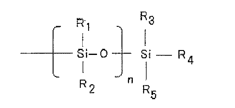
- Examples thereof include 2-(trimethylsilyl) sodium ethanesulfonate and 2-(trimethylsilyl) sodium propane sulfonate.
- In the invention, the cerium oxide is dispersed into a diluting solution using the above surfactant, and the cerium oxide-containing dispersion is dispersed into the binder. Such means can further enhance the dispersibility of the cerium oxide into the binder, and makes it possible to suppress brown discoloration which is caused by exposing ultraviolet to the surfactant.
- It is also possible to carry out the dispersion by a mechanical dispersion method in addition to the method using the above dispersant. In such a case, the dispersion may be carried out by using general mixing apparatus such as sand mill, ball mill, and paint shaker.
- The protective film of the invention may have various functional layers on the plastic film or the coating layer without diverting the scope of the invention. Examples of the functional layer include a matting agent layer, a protective layer, an antistatic layer, a smoothening layer, an adhesiveness improving layer, a light shielding layer, an antireflection layer, a hard coat layer, a stress relaxing layer, an antifogging layer, an anti-soiling layer, a printable layer, an adhesive layer, a barrier layer, etc.
- In the protective film, the barrier layer may be disposed on the plastic film or the coating layer, preferably on the plastic layer. The barrier layer may be provided on the surface of the plastic layer or be provided on the plastic layer through another functional layer.
- The barrier layer preferably comprises at least one organic layer and at least one inorganic layer, and may comprise two or more organic layers and two or more inorganic layers laminated alternately. The organic layer may be applied to the technique disclosed in
JP-A- 2009-081123 JP-A-2009-081123 - The absorbance of the protective film of the invention may be 3 or more at wavelength of 330 nm, and may be further 3.5 or more at wavelength of 330 nm.
- The haze of the protective film of the invention may be controlled to be 5% or less, further may be controlled to be 4.5% or less, and may be particularly to be controlled to 3% or less.
- The protective film of the invention can be used for various applications, preferably a protective member of a sheet used for a solar cell, particularly preferably of a protective member of a front sheet used for a solar cell.
- The protective film of the invention can be used as a protective member of a sheet used for a solar cell. Solar cells generally have a construction wherein an active part which practically operates as a solar cell is disposed between a pair of substrates. The protective film of the invention may be used as a protective member for one or both of the pair of substrates, preferably is used as a protective member for a front sheet for a solar cell. In addition, the protective film itself may be used as a sheet for a solar cell.
- The solar cell devices for which the protective film of the invention is favorably used are not specifically defined. For example, they include single crystal silicon-based solar cell devices, polycrystalline silicon-based solar cell devices, single-junction or tandem-structure amorphous silicon-based solar cell devices, gallium-arsenic (GaAs), indium-phosphorus (InP) or the like III-V Group compound semiconductor-based solar cell devices, cadmium-tellurium (CdTe) or the like II-VI Group compound semiconductor-based solar cell devices, copper/indium/selenium (CIS-based), copper/indium/gallium/selenium (CIGS-based), copper/indium/gallium/selenium/sulfur (CIGSS-based) or the like I-III-VI Group compound semiconductor-based solar cell devices, dye-sensitized solar cell devices, organic solar cell devices, etc. Above all, in the invention, the solar cell devices are preferably copper/indium/selenium (CIS-based), copper/indium/gallium/selenium (CIGS-based), copper/indium/gallium/selenium/sulfur (CIGSS-based) or the like I-III-VI Group compound semiconductor-based solar cell devices.
- The characteristics of the invention are described more concretely with reference to the following Examples. In the following Examples, the material used, its amount and the ratio, the details of the treatment and the treatment process may be suitably modified or changed not overstepping the sprit and the scope of the invention. Accordingly, the invention should not be limitatively interpreted by the Examples mentioned below.
- A silicone alkoxide series binder composition was prepared by mixing 100 parts by weight of alkoxy silicon oligomer as a siloxane series binder (manufactured by Shin-Etsu Chemical Co., Ltd., X-40-9250), 5 parts by weight of titanium series curing catalyst (manufactured by Shin-Etsu Chemical Co., Ltd., D-20) and 100 parts by weight of butanol.
- 30 parts by weight of Needral U-15 (manufactured by Taki Chemical Co., Ltd.; the average particle size is 10 nm, the content of CeO2 is 15% by weight) was diluted with 90 parts by weight of water. To this, 180 parts by weight of aqueous solution of 2-(trimethylsilyl) sodium ethanesulfonate (manufactured by ALDRICH) as a surfactant in the concentration of 1% by weight was added, to thereby obtain deposition. The deposition was filtrated and washed, to thereby obtain wet cake. This wet cake was re-dispersed into 1-Butanol, to thereby obtain a CeO2 particle-containing butanol dispersion liquid.
- To the above binder composition, the above CeO2 particle-dispersion liquid was added so that the solid content of CeO2 particles in the coating layer was controlled to be 30% by weight, and stirred to thereby obtain a coating solution.
- On a polyethylene terephthalate film (manufactured by Fujifilm Corporation, FQ125), the above coating composition was coated so as to have a thickness of 5µm, and then dried for 6 hours at room temperature, to thereby obtain a protective film.
- For measuring ultraviolet absorption and ultraviolet absorption retention, the above coating composition was coated so as to have a thickness of 5µm on a glass substrate, and then dried for 6 hours at room temperature, to thereby obtain a sample for the tests.
- A protective film and a sample for the tests were obtained according to the same method as that in Example 1, except that 2-(trimethylsilyl) sodium ethanesulfonate as a surfactant was replaced with 2-(trimethylsilyl) sodium propane sulfonate. Comparative Example 1 (Formation of Protective Film Using ZnO Particles Having an Average Particle Size of 4 nm Instead of CeO2 Particles)
- To 65 parts by weight of zincacetatedihydrate, 150 parts by weight of methanol was added, to thereby obtain a clouded solution. To this, 150 parts by weight of octylamine was added and stirred for 20 minutes, to thereby obtain a clear solution. To this, 30 parts by weight of potassiumhydrate dissolved in 100 parts by weight of methanol was added, to thereby obtain a clouded solution again. Then, the solution was centrifuged at 4000 rpm for 30 minutes followed by removing its supernatant, which was repeated three times, to thereby obtain white powder. To this, 200 parts by weight of 1-butanol was added, to thereby obtain zinc oxide nano particles-butanol dispersion liquid. The obtained zinc oxide particles were ZnO particles having an average particle size of 4 nm. The above ZnO particles-butanol dispersion liquid was added to the binder composition prepared in Example 1 so that the solid content of ZnO particles was controlled to be 30% by weight, relative to the binder composition, and stirred to thereby obtain a coating composition.
- A protective film and sample for the tests were obtained according to the same method as that in Example 1, except that the coating composition was replaced with the above.
- 100 parts by weight of methyl trimethoxy silane, 20 parts by weight of tetramethoxy silane, 150 parts by weight of isopropylalcoholorgano silica sol (manufactured by JGC Catalysts and Chemicals Ltd., OSCAL1432, the content of SiO2 is 30% by weight), 40 parts by weight of dimethyl dimethoxy silane and 100 parts by weight of isopropyl alcohol were mixed, and then, 200 parts by weight of water was added and further stirred. This was controlled to have a weight-average molecular weight (Mw) of 1200 in a thermostatic bath at 60°C, to thereby obtain a silicon alkoxide series coating composition.
- To 50 parts by weight of methyltrimethoxysilane, 40 parts by weight of zinc oxide fine particles having an average particle size of 40 nm, 5 parts by weight of carbonic acid series dispersant and 5 parts by weight of diluting solvent were added and stirred with a disper for 30 minutes, and then, dispersed using glass beads having a size of 1 mm with a disperser (manufactured by WAB, DYNO-Mill, the flow rate is 25 kg/hr, the vessel bulk is 1.5 1, repeated five times), to thereby obtain zinc oxide fine particles mill base.
- The mill base for zinc oxide fine particle was add to have a concentration of 15% by weight of the zinc oxide fine particles having an average particle size of 40 nm to the above silicon alkoxide series coating composition. By the above method, the coating composition disclosed in
JP-A-2000-334373 - A protective film and a sample for the tests were obtained according to the same method as that in Example 1, except that the coating composition was replaced with the above coating composition.
- A cerium oxide particle-containing butanol dispersion liquid was obtained by adding 100 parts by weight of butanol and 50 parts by weight of X-40-9250 to 10 parts by weight of cerium oxide particles(manufactured by Showa Denko K.K., GPL grade, C1010, the average particle size is 220 nm) and dispersing it with a planetary ball mill.
- A cerium oxide particle-containing butanol dispersion liquid was added to the above binder composition so that the solid content of CeO2 particles was controlled to be 30% by weight, relative to the coating layer, and stirred, to thereby obtain a coating composition.
- A protective film and a sample for the tests were obtained according to the same method as that in Example 1, except that the coating composition was replaced with the above coating composition.
- A protective film and a sample for the tests were obtained according to the same method as that in Example 1, except that the solid content of cerium oxide particles is controlled to be 9% by weight.
- 55 parts by weight of methyl methacrylate, 5 parts by weight of 2-ethylhexyl acrylate, 5 parts by weight of cyclohexyl methacrylate, 10 parts by weight of γ -methacryloxy propyl trimethoxysilane, 20 parts by weight of glycidyl methacrylate, 5 parts by weight of 4-(meth)acryloyloxy-2,2,6,6-tetramethylpiperidine, 75 parts by weight of i-buthyl alcohol, 50 parts by weight of methylethylketone, and 25 parts by weight of methanol were mixed, and then, stirred and heated up to 80° C. To this mixture, a solution of 3 parts by weight of azobis isobutyronitrile in 8 parts by weight of xylene was incrementally dropped for 30 minutes, and then, reacted at 80° C for 5 hours. Then, to this, 36 parts by weight of methylethylketone was added and stirred, to thereby prepare a solution of polymer having Mw of 12, 000 in the solid concentration of around 35%.
- 118 parts by weight of the polymer solution, 24 parts by weight of methyltrimethoxysilane, 10 parts by weight of dimethyldimethoxysilane, 2 parts by weight of di-i-propoxyethyl acetate aluminium and 10 parts by weight of i-propylalcohol were mixed, and stirred and heated up to 50° C. To this, 6 parts by weight of water was incrementally added for 30 minutes and reacted at 60° C for 4 hours. Then, to this, 2 parts by weight of acetylacetone was added and stirred for 1 hour, and then, cooled to a room temperature. 40 parts by weight of methyl isobutylketone as a diluent solution was added under being stirred, to thereby prepare a binder composition corresponding to a under coating composition disclosed in
JP-A-2002-371234 - A coating composition was prepared by adding the CeO2 particles butanol dispersion liquid in Example 1 into the above binder composition so that the solid concentration of CeO2 particles is 30% by weight, relative to the coating layer and stirring it.
- A protective film and a sample for the tests were obtained according to the same method as that in Example 1, except that the coating composition was replaced with the above coating composition.
- A protect film and sample for the tests were obtained according to the same method as that in Example 1, except that 2-(trimethylsilyl) sodium ethanesulfonate as a surfactant was replaced with sodium dodecylbenzenesulfonate.
- A binder composition was prepared by mixing 2 parts by weight of polyvinylalcohol "PVA-117" (manufactured by kuraray Co. , Ltd.), as a binder, and 98 parts by weight of water.
- A coating composition was prepared by adding Needlal U-15 (manufactured by Taki Chemical Co. , Ltd.; the particle average size is 10 nm, the content of CeO2 is 15% by weight) so as to have a solid concentration of CeO2 particles of 30% by weight, relative to the coating layer and stirring it.
- A protective film and a sample for the tests were obtained according to the same method as that in Example 1, except that the coating composition was replaced with the above coating composition.
- A protective film and a sample for the tests were obtained according to the same method as that in Example 1, except that Needlal U-15 was replaced with Tynoc AM-15 (manufactured by Taki Chemical Co. , Ltd. ; the average particle size of 20 nm, the content of TiO2 is 15% by weight).
- A protective film and a sample for the tests were obtained according to the same method as that in Example 1, except that the siloxane series binder X-40-9250 was replaced with a binder composition composed of 80 parts by weight of X-40-9250 and 20 parts by weight of KR-500 (manufactured by Shin-Etsu Chemical Co., Ltd.) in the preparation of a binder composition.
- A protective film and a sample for the tests were obtained according to the same method as that in Example 1, except that the siloxane series binder X-40-9250 was replaced with a binder composition composed of 80 parts by weight of X-40-9250, 10 parts by weight of X-40-9225 (manufactured by Shin-Etsu Chemical Co., Ltd.) and 10 parts by weight of KR-500 in the preparation of a binder composition.
- A protective film and a sample for the tests were obtained according to the same method as that in Example 1, except that the polyethylene terephthalate film was replaced with a polymethylmethacrylate film (manufactured by Sumitomo Chemical Co. Ltd., technolloy S001, having a thickness of 75 µm).
- A protective film and a sample for the tests were obtained according to the same method as that in Example 1, except that the polyethylene terephthalate film was replaced with a polycarbonate film (manufactured by Teijin Chemicals Ltd., Pure-Ace, having a thickness of 100µm).
- For the obtained protective films and samples for the test, the following evaluations were carried out.
- According to JIS K7361 and JIS K7361-1, haze for each of the protective films was measured using a haze meter (manufactured by Nippon Denshioku Industries Co., Ltd., NDH 5000).
- Optical transmittance of each of the protective films was measured according to JIS R3106.
- Absorbance spectrum at 330 nm for each of the samples for the tests was measured using an ultraviolet-visible spectralphotometer (manufactured by JASCO Corporation, V-560).
- The absorbance spectrum was measured for the samples for the test instead of the protective films of the invention because a plastic film which is used in the protective film in Examples may not be correctly measured for its absorbance spectrum according to this measuring method. The reason is that ultraviolet absorption capacity of a protective layer such as that in Comparative Example 1 reduces by ultraviolet exposure, and a plastic film which is the underlayer of such a protective layer deteriorates and turns yellow after the ultraviolet expose, so that the absorbance for the protective layer itself may not be correctly measured. However, it was confirmed that absorbance value measured for the samples for the tests shows a similar tendency to that for the corresponding protective film. This is because the clear and colorless PET film of which the protective layer protects from ultraviolet and suppresses its deterioration has very little absorbance at 330 nm. Thus, each of the samples for the test shows absorbance of the corresponding protective film.
- Ultraviolet exposure test to the samples for the tests was carried at 0.53 kW/m2 (wavelength was 300 to 400 nm) for 1000 hours using a Metaling Vertical Weather Meter (manufactured by Suga Test Instruments Co., Ltd., MV3000). The test was carried out under the following condition;
black panel temperature was 63°C, and
humidity in a basin was 50%.
Absorbance at 330 nm before and after the above ultraviolet exposure test was measured using an ultraviolet-visible spectralphotometer (manufactured by JASCO Corporation, V-560). The results are shown according to the following formula;
- The protective films after the ultraviolet expose were visually observed.
- Bending test was carried out according the following method. The protective film of which the above ultraviolet exposure test was carried out was cut into 10 cm × 10 cm, the edges of the protective film were stuck to form cylindrical shape so that the coating layer becomes outside. The cylindrical shape-protective film was put between two transfer rollers having a diameter of 12 mm at a tension of about 1 N, and was transferred as it was turned around at 30 cm/min with careful attention to keep complete contact between the laminate film and the roller and not to slide the laminate film. After that, visual observation of crack which occurs on the protective film was carried out.
○ : crack did not occur.
×: crack occurred. - After the above bending test, adhesion of a protective film was tested in a cross-cut peeling test according to JIS K5400. The surface of the protective film was cut with a cutter knife at an angle of 90° to the film surface, at intervals of 1 mm, thereby forming 100 cross cuts at intervals of 1 mm. A 2 cm wide Mylar Tape (manufactured by Nitto Denko Corporation, polyester tape No. 31B) was stuck to it, and using a tape peeling tester, the tape was peeled off. Of the 100 cross cuts on the surface of the sample, the number (n) of the cross cuts having remained on the surface of the sample without being peeled away was counted. The results are shown the table below.
[Table 1] Haze Measurement (%) Optical Transmittance (%) Ultraviolet Absorbance Retention (%) Absorbance Flexibility Evacuation According to Bending Test Adhesion after Bending Test (n /100) External Observation Example 1 1 92.5 99.5 3.3 ○ 98 Transparency Example 2 1.3 91.5 99.1 3.2 ○ 95 Transparency Example 3 1.1 92 99.3 3.2 ○ 97 Transparency Example 4 1.2 92.4 99.1 3.2 ○ 95 Transparency Example 5 1 92.3 99.1 3.3 ○ 86 Transparency Example 6 1 91.3 99.2 3.3 ○ 84 Transparency Comp. Exam. 1 0.7 92.9 5 2.5 × 0 Yellow Turbidity Comp. Exam. 2 15.3 84.3 90.1 2.2 × 4 White Turbidity Comp. Exam. 3 25.5 81.5 99.1 3.1 ○ 94 White Turbidity Comp. Exam. 4 1 89.5 99.2 2.2 × 6 Yellow Turbidity Comp. Exam. 5 4.8 87.2 98.2 3 × 5 Transparency Comp. Exam. 6 1.6 90.2 99.1 3 × 12 Brown Discoloration Comp. Exam. 7 1.1 87.6 99 3.1 × 0 Transparency Comp. Exam. 8 19.7 80.2 99.1 3.2 × 3 White Turbidity - A protective film having a layer structure shown in
Fig. 1 was formed. On a surface of a polyethylene terephthalate film (manufactured by Toray Industries, Inc., T60), anorganic layer 2 and aninorganic layer 3 were formed according to the same method as that of Sample 101 in Example inJP-A-2009-081123 barrier layer 4. According to the same method as that in Example 1, a coating layer 5 was formed on the surface at the side opposite to the side at which the barrier layer of the film was deposited. - The protective film having the barrier layer in the above Example and the CIS series thin film solar cell described in Example 1 in
JP-A-2009-99973
Claims (15)
- A protective film comprising a plastic film and a coating layer on the surface of the plastic film, wherein the coating layer comprises a binder and cerium oxide particles dispersed in the binder, the cerium oxide particles are dispersed into the binder by using a surfactant comprising a Si-O bond and/or a Si-C bond, the content of the cerium oxide particles in the coating layer is in a range of 10% by weight or more, the cerium oxide particles have an average particle size of 50 nm or less, and the binder has an average composition represented by the following formula (1); formula (1)
R11 mSi(OR12)nO(4-m-n)/2
wherein R11 is a methyl group, an ethyl group, or a phenyl group, R12 is an alkyl group having carbon atoms of 1 to 8, R11's may be the same or different, R12's may be the same or different, and m and n satisfy 0.2≦m≦2, 0.01≦n≦3, and m+n<4. - The protective film according to Claim 1, wherein the cerium oxide particles have an average particle size of 30 nm or less.
- The protective film according to Claim 1 or 2, wherein the coating layer comprises the cerium oxide particles in an amount of 10 to 45% by weight.
- The protective film according to any one of Claims 1 to 3, wherein the plastic film comprises polycarbonate, polymethyl methacrylate or polyolefin.
- The protective film according to any one of Claims 1 to 3, wherein the plastic film comprises polyethylene terephthalate.
- The protective film according to any one of Claims 1 to 5, wherein the surfactant is an anionic surfactant or a cationic surfactant.
- The protective film according to any one of Claims 1 to 6, wherein the cerium oxide particles have an average particle size of 3 nm or more.
- The protective film according to any one of Claims 1 to 7, wherein the coating layer comprises the binder in an amount of 50 to 90% by weight and the cerium oxide particles in an amount of 10 to 45% by weight, and the cerium oxide particles have an average particle size of 3 to 50 nm.
- The protective film according to any one of Claims 1 to 8, which comprises a barrier layer on the plastic film or the coating layer.
- The protective film according to any one of Claims 1 to 8, which comprises a barrier layer on the plastic film.
- The protective film according to Claim 9 or 10, wherein the barrier layer comprises at least one organic layer and at least one inorganic layer.
- The protective film according to any one of Claims 1 to 11, which has an absorbance of 3 or more at a wavelength of 330 nm.
- The protective film according to any one of Claims 1 to 12, which has a haze of 5% or less.
- The protective film according to any one of Claims 1 to 13, wherein the coating layer comprises a curing catalyst.
- A front sheet for a solar cell, comprising the protective film according to any one of Claims 1 to 14.
Applications Claiming Priority (1)
| Application Number | Priority Date | Filing Date | Title |
|---|---|---|---|
| JP2009214354A JP5258717B2 (en) | 2009-09-16 | 2009-09-16 | Protective film and solar cell front sheet |
Publications (2)
| Publication Number | Publication Date |
|---|---|
| EP2299487A2 true EP2299487A2 (en) | 2011-03-23 |
| EP2299487A3 EP2299487A3 (en) | 2011-06-22 |
Family
ID=43446412
Family Applications (1)
| Application Number | Title | Priority Date | Filing Date |
|---|---|---|---|
| EP10176803A Withdrawn EP2299487A3 (en) | 2009-09-16 | 2010-09-15 | Protective film and front sheet for solar cell |
Country Status (5)
| Country | Link |
|---|---|
| US (1) | US20110064942A1 (en) |
| EP (1) | EP2299487A3 (en) |
| JP (1) | JP5258717B2 (en) |
| KR (1) | KR101774051B1 (en) |
| CN (1) | CN102019735B (en) |
Families Citing this family (7)
| Publication number | Priority date | Publication date | Assignee | Title |
|---|---|---|---|---|
| JP5601944B2 (en) * | 2010-06-28 | 2014-10-08 | 帝人株式会社 | Touch panel device and display device with touch panel device |
| JP2012218209A (en) * | 2011-04-05 | 2012-11-12 | Jsr Corp | Method for manufacturing protective sheet for solar cell and protective sheet for solar cell |
| JP5352702B2 (en) * | 2011-08-03 | 2013-11-27 | 東洋インキScホールディングス株式会社 | Solar cell back surface protection sheet and solar cell module |
| US11104814B2 (en) * | 2016-02-15 | 2021-08-31 | Momentive Performance Materials Inc. | Primer formulations with improved photostability |
| AU2019202080B2 (en) * | 2018-04-05 | 2023-11-09 | Rohm And Haas Company | Hydrophobic pigment modification |
| CN112531055B (en) * | 2020-12-24 | 2021-11-02 | 中山德华芯片技术有限公司 | A kind of flexible solar cell and preparation method thereof |
| CN112701167B (en) * | 2020-12-24 | 2022-04-12 | 中山德华芯片技术有限公司 | Polyimide-based membrane material, preparation method and application |
Citations (7)
| Publication number | Priority date | Publication date | Assignee | Title |
|---|---|---|---|---|
| US4810742A (en) * | 1988-02-01 | 1989-03-07 | Occidental Chemical Corporation | UV stable, impact resistant, flame retarded ABS composition containing aliphatic resin |
| JP2000334373A (en) | 1999-03-24 | 2000-12-05 | Matsushita Electric Works Ltd | Inorganic coated article |
| JP2002371234A (en) | 2000-12-06 | 2002-12-26 | Jsr Corp | Coating composition, method for producing the same, cured product, and coating film |
| JP2004168057A (en) | 2002-11-07 | 2004-06-17 | Matsushita Electric Works Ltd | Fluorine composite resin film and solar cell |
| JP2006255927A (en) | 2005-03-15 | 2006-09-28 | Teijin Dupont Films Japan Ltd | Surface protective film for solar cell and solar cell laminate using the same |
| JP2009081123A (en) | 2007-09-07 | 2009-04-16 | Fujifilm Corp | Top emission type organic EL device and method for producing the same. |
| JP2009099973A (en) | 2007-09-28 | 2009-05-07 | Fujifilm Corp | Solar cell |
Family Cites Families (7)
| Publication number | Priority date | Publication date | Assignee | Title |
|---|---|---|---|---|
| US4657959A (en) * | 1985-11-15 | 1987-04-14 | Minnesota Mining And Manufacturing Company | Hydrophilic silicones |
| US6264859B1 (en) * | 1986-10-03 | 2001-07-24 | Ppg Industries Ohio, Inc. | Optically transparent UV-protective coatings |
| JPH0687189A (en) * | 1992-09-08 | 1994-03-29 | Toray Ind Inc | Transparent molded material |
| DE19858998A1 (en) * | 1998-12-21 | 2000-06-29 | Bayer Ag | Coating compositions containing cerium dioxide |
| US7056584B2 (en) * | 2002-10-11 | 2006-06-06 | General Electric Company | Bond layer for coatings on plastic substrates |
| JP4938239B2 (en) * | 2004-04-23 | 2012-05-23 | シャープ株式会社 | Display device |
| JP2010037457A (en) * | 2008-08-06 | 2010-02-18 | Nitto Denko Corp | Silicone resin composition containing fine inorganic particle |
-
2009
- 2009-09-16 JP JP2009214354A patent/JP5258717B2/en not_active Expired - Fee Related
-
2010
- 2010-09-14 CN CN201010282888.4A patent/CN102019735B/en not_active Expired - Fee Related
- 2010-09-15 KR KR1020100090715A patent/KR101774051B1/en not_active Expired - Fee Related
- 2010-09-15 US US12/882,583 patent/US20110064942A1/en not_active Abandoned
- 2010-09-15 EP EP10176803A patent/EP2299487A3/en not_active Withdrawn
Patent Citations (7)
| Publication number | Priority date | Publication date | Assignee | Title |
|---|---|---|---|---|
| US4810742A (en) * | 1988-02-01 | 1989-03-07 | Occidental Chemical Corporation | UV stable, impact resistant, flame retarded ABS composition containing aliphatic resin |
| JP2000334373A (en) | 1999-03-24 | 2000-12-05 | Matsushita Electric Works Ltd | Inorganic coated article |
| JP2002371234A (en) | 2000-12-06 | 2002-12-26 | Jsr Corp | Coating composition, method for producing the same, cured product, and coating film |
| JP2004168057A (en) | 2002-11-07 | 2004-06-17 | Matsushita Electric Works Ltd | Fluorine composite resin film and solar cell |
| JP2006255927A (en) | 2005-03-15 | 2006-09-28 | Teijin Dupont Films Japan Ltd | Surface protective film for solar cell and solar cell laminate using the same |
| JP2009081123A (en) | 2007-09-07 | 2009-04-16 | Fujifilm Corp | Top emission type organic EL device and method for producing the same. |
| JP2009099973A (en) | 2007-09-28 | 2009-05-07 | Fujifilm Corp | Solar cell |
Also Published As
| Publication number | Publication date |
|---|---|
| KR20110030385A (en) | 2011-03-23 |
| CN102019735B (en) | 2015-04-29 |
| US20110064942A1 (en) | 2011-03-17 |
| KR101774051B1 (en) | 2017-09-01 |
| JP2011062877A (en) | 2011-03-31 |
| CN102019735A (en) | 2011-04-20 |
| JP5258717B2 (en) | 2013-08-07 |
| EP2299487A3 (en) | 2011-06-22 |
Similar Documents
| Publication | Publication Date | Title |
|---|---|---|
| EP2295491B1 (en) | Protective film and front sheet for solar cell | |
| EP2299487A2 (en) | Protective film and front sheet for solar cell | |
| EP2407521B1 (en) | Coating composition, coating film, laminate, and process for production of laminate | |
| US7905950B2 (en) | Coating composition and resin multilayer body | |
| EP3223043B1 (en) | Low refractive layer and anti-reflection film comprising same | |
| JP5414426B2 (en) | Composite film | |
| EP2827379B1 (en) | Sealing sheet for back surface of solar cell, and solar cell module | |
| KR102245476B1 (en) | Anti-reflection film, polarizing plate, and image display device | |
| TW201536864A (en) | Aqueous coating agent, film, film manufacturing method, laminate, and solar cell module | |
| KR101846959B1 (en) | Water-based anti-soiling agent, anti-soiling layer, layered body, and solar battery module | |
| US20180112459A1 (en) | Heat ray reflective material, window, and method for manufacturing heat ray reflective material | |
| JP2010238759A (en) | Solar cell module back surface protective sheet, solar cell module, coating liquid for forming fluororesin cured coating film on back surface protective sheet for solar cell module | |
| EP2539941B1 (en) | Back sheet for solar cell, method for producing the same, and solar cell module | |
| TWI620667B (en) | Barrier laminate, gas barrier film, and component | |
| CN104487246A (en) | Back sheet for photovoltaic cell module and photovoltaic cell module including the back sheet | |
| JP2013021272A (en) | Back sheet for solar cell and manufacturing method therefor and solar cell module | |
| JP6071937B2 (en) | Solar cell back surface protection sheet and solar cell module | |
| KR102867921B1 (en) | Laminated film for bifacial solar cell module and solar cell module comprising the same | |
| KR102876112B1 (en) | Laminated film for solar cell module having excellent radiative cooling property and solar cell module comprising the same | |
| JP2012023148A (en) | Protective sheet for solar cell, and solar cell | |
| JP2012015295A (en) | Protective sheet for solar cell and solar cell | |
| WO2013024884A1 (en) | Polymer sheet for solar cell module, manufacturing method for same, back sheet for solar cell module, and solar cell module | |
| JP6182013B2 (en) | Thermal barrier composition, thermal barrier member, and thermal barrier coating |
Legal Events
| Date | Code | Title | Description |
|---|---|---|---|
| PUAI | Public reference made under article 153(3) epc to a published international application that has entered the european phase |
Free format text: ORIGINAL CODE: 0009012 |
|
| AK | Designated contracting states |
Kind code of ref document: A2 Designated state(s): AL AT BE BG CH CY CZ DE DK EE ES FI FR GB GR HR HU IE IS IT LI LT LU LV MC MK MT NL NO PL PT RO SE SI SK SM TR |
|
| AX | Request for extension of the european patent |
Extension state: BA ME RS |
|
| PUAL | Search report despatched |
Free format text: ORIGINAL CODE: 0009013 |
|
| AK | Designated contracting states |
Kind code of ref document: A3 Designated state(s): AL AT BE BG CH CY CZ DE DK EE ES FI FR GB GR HR HU IE IS IT LI LT LU LV MC MK MT NL NO PL PT RO SE SI SK SM TR |
|
| AX | Request for extension of the european patent |
Extension state: BA ME RS |
|
| 17P | Request for examination filed |
Effective date: 20111212 |
|
| 17Q | First examination report despatched |
Effective date: 20120618 |
|
| STAA | Information on the status of an ep patent application or granted ep patent |
Free format text: STATUS: THE APPLICATION IS DEEMED TO BE WITHDRAWN |
|
| 18D | Application deemed to be withdrawn |
Effective date: 20160421 |