EP2299457A2 - Electromagnet - Google Patents
Electromagnet Download PDFInfo
- Publication number
- EP2299457A2 EP2299457A2 EP10009439A EP10009439A EP2299457A2 EP 2299457 A2 EP2299457 A2 EP 2299457A2 EP 10009439 A EP10009439 A EP 10009439A EP 10009439 A EP10009439 A EP 10009439A EP 2299457 A2 EP2299457 A2 EP 2299457A2
- Authority
- EP
- European Patent Office
- Prior art keywords
- tube
- electrically conductive
- magnetic body
- conductive element
- ring
- Prior art date
- Legal status (The legal status is an assumption and is not a legal conclusion. Google has not performed a legal analysis and makes no representation as to the accuracy of the status listed.)
- Granted
Links
- 238000007789 sealing Methods 0.000 claims description 25
- 239000011248 coating agent Substances 0.000 claims description 10
- 238000000576 coating method Methods 0.000 claims description 10
- 238000005520 cutting process Methods 0.000 claims description 9
- 239000000463 material Substances 0.000 claims description 9
- 239000004020 conductor Substances 0.000 claims description 8
- OKTJSMMVPCPJKN-UHFFFAOYSA-N Carbon Chemical compound [C] OKTJSMMVPCPJKN-UHFFFAOYSA-N 0.000 claims description 6
- 229910052799 carbon Inorganic materials 0.000 claims description 4
- 239000012799 electrically-conductive coating Substances 0.000 claims description 3
- 239000000428 dust Substances 0.000 claims description 2
- 229910002804 graphite Inorganic materials 0.000 claims description 2
- 239000010439 graphite Substances 0.000 claims description 2
- 239000002923 metal particle Substances 0.000 claims description 2
- 239000012811 non-conductive material Substances 0.000 claims description 2
- 238000006748 scratching Methods 0.000 claims 1
- 230000002393 scratching effect Effects 0.000 claims 1
- 238000004519 manufacturing process Methods 0.000 description 12
- 230000007797 corrosion Effects 0.000 description 5
- 238000005260 corrosion Methods 0.000 description 5
- 238000003780 insertion Methods 0.000 description 5
- 230000037431 insertion Effects 0.000 description 5
- 239000003566 sealing material Substances 0.000 description 5
- 239000002245 particle Substances 0.000 description 4
- 239000011324 bead Substances 0.000 description 3
- 150000001875 compounds Chemical class 0.000 description 3
- 230000002349 favourable effect Effects 0.000 description 3
- 239000010410 layer Substances 0.000 description 3
- 238000000034 method Methods 0.000 description 3
- 230000035515 penetration Effects 0.000 description 3
- 230000002093 peripheral effect Effects 0.000 description 3
- 239000004033 plastic Substances 0.000 description 3
- 230000001681 protective effect Effects 0.000 description 3
- 239000000565 sealant Substances 0.000 description 3
- 230000006835 compression Effects 0.000 description 2
- 238000007906 compression Methods 0.000 description 2
- 230000001419 dependent effect Effects 0.000 description 2
- 238000002844 melting Methods 0.000 description 2
- 230000008018 melting Effects 0.000 description 2
- 239000002184 metal Substances 0.000 description 2
- 238000000926 separation method Methods 0.000 description 2
- 208000031872 Body Remains Diseases 0.000 description 1
- 230000004913 activation Effects 0.000 description 1
- 238000004026 adhesive bonding Methods 0.000 description 1
- 238000005452 bending Methods 0.000 description 1
- 230000009286 beneficial effect Effects 0.000 description 1
- 230000008901 benefit Effects 0.000 description 1
- 230000015572 biosynthetic process Effects 0.000 description 1
- 238000005266 casting Methods 0.000 description 1
- 239000003795 chemical substances by application Substances 0.000 description 1
- 238000013461 design Methods 0.000 description 1
- 230000006866 deterioration Effects 0.000 description 1
- 238000011161 development Methods 0.000 description 1
- 238000006073 displacement reaction Methods 0.000 description 1
- 239000013013 elastic material Substances 0.000 description 1
- 230000006872 improvement Effects 0.000 description 1
- 238000001746 injection moulding Methods 0.000 description 1
- 230000010354 integration Effects 0.000 description 1
- 239000007788 liquid Substances 0.000 description 1
- 230000007774 longterm Effects 0.000 description 1
- 230000007257 malfunction Effects 0.000 description 1
- 230000013011 mating Effects 0.000 description 1
- 230000000149 penetrating effect Effects 0.000 description 1
- 238000004382 potting Methods 0.000 description 1
- 238000002360 preparation method Methods 0.000 description 1
- 230000008569 process Effects 0.000 description 1
- 239000011253 protective coating Substances 0.000 description 1
- 230000008439 repair process Effects 0.000 description 1
- 239000002689 soil Substances 0.000 description 1
- 238000005476 soldering Methods 0.000 description 1
- 230000006641 stabilisation Effects 0.000 description 1
- 238000011105 stabilization Methods 0.000 description 1
- 210000002784 stomach Anatomy 0.000 description 1
- 239000002344 surface layer Substances 0.000 description 1
- 238000012549 training Methods 0.000 description 1
- 238000003466 welding Methods 0.000 description 1
Images


Classifications
-
- H—ELECTRICITY
- H01—ELECTRIC ELEMENTS
- H01F—MAGNETS; INDUCTANCES; TRANSFORMERS; SELECTION OF MATERIALS FOR THEIR MAGNETIC PROPERTIES
- H01F7/00—Magnets
- H01F7/06—Electromagnets; Actuators including electromagnets
- H01F7/08—Electromagnets; Actuators including electromagnets with armatures
- H01F7/127—Assembling
-
- H—ELECTRICITY
- H01—ELECTRIC ELEMENTS
- H01F—MAGNETS; INDUCTANCES; TRANSFORMERS; SELECTION OF MATERIALS FOR THEIR MAGNETIC PROPERTIES
- H01F7/00—Magnets
- H01F7/06—Electromagnets; Actuators including electromagnets
- H01F7/08—Electromagnets; Actuators including electromagnets with armatures
- H01F7/16—Rectilinearly-movable armatures
- H01F7/1607—Armatures entering the winding
-
- H—ELECTRICITY
- H01—ELECTRIC ELEMENTS
- H01F—MAGNETS; INDUCTANCES; TRANSFORMERS; SELECTION OF MATERIALS FOR THEIR MAGNETIC PROPERTIES
- H01F7/00—Magnets
- H01F7/06—Electromagnets; Actuators including electromagnets
- H01F7/08—Electromagnets; Actuators including electromagnets with armatures
- H01F7/081—Magnetic constructions
- H01F2007/083—External yoke surrounding the coil bobbin, e.g. made of bent magnetic sheet
-
- H—ELECTRICITY
- H01—ELECTRIC ELEMENTS
- H01F—MAGNETS; INDUCTANCES; TRANSFORMERS; SELECTION OF MATERIALS FOR THEIR MAGNETIC PROPERTIES
- H01F7/00—Magnets
- H01F7/06—Electromagnets; Actuators including electromagnets
- H01F7/08—Electromagnets; Actuators including electromagnets with armatures
- H01F7/16—Rectilinearly-movable armatures
- H01F7/1607—Armatures entering the winding
- H01F2007/163—Armatures entering the winding with axial bearing
Definitions
- the invention relates to an electromagnet with a magnetic body, which is connected to a Tubusrohr, wherein means for fixing the magnetic body are provided on Tubusrohr and the means at least one on the one hand the Tubusrohr, on the other hand, the magnetic body contacting, electrically conductive element for electrical connection of Tubusrohr and magnetic body.
- Electromagnets with a tube tube and a magnetic body arranged thereon are known.
- the magnetic body is attached to the Tubusrohr, deferred or pressed and so more or less permanently connected to the Tubusrohr.
- the Tubusrohr serves as a guide of a magnet armature, which is movable by application of electrical current.
- Electromagnets typically have a protective conductor which is mounted so that an electrical connection between the metallic components of the electromagnet and the soil is made. Particularly important here is that the protective conductor contacts all metallic components of the electromagnet.
- a separation of the connection between the tube tube and the magnetic body occurs during long-term use, which is often accompanied by vibrations. With this separation, the protective conductor is often interrupted so that there is no longer sufficient grounding of the electromagnet.
- the magnetic body dissolves from Tubusrohr, also a malfunction of the electromagnet occur, which is undesirable in continuous use and leads to downtime and repair costs and associated costs.
- an electromagnet which comprises a tube tube as a guide for a magnet armature and a magnetic body.
- the magnetic body connected to the Tubusrohr.
- the electromagnet according to the invention is characterized in that at least one means for fixing the magnetic body is provided on Tubusrohr. By this means, a permanent connection between Tubusrohr and magnetic body can be made.
- the means comprises at least one electrically conductive element for electrically connecting Tubusrohr and magnetic body.
- the electrically conductive element contacted on the one hand, the Tubusrohr and on the other hand, the magnetic body.
- the electrically conductive element contacts metallic surfaces of the tube tube or of the magnet body, so that a current can flow unhindered here.
- the electromagnet used according to the invention for attachment of magnetic body and tube tube or fixing the magnetic body on Tubusrohr can as nut, clamp, splint, bracket, connector, clip, clamping ring or in any other way, the safe and reliable and before Ensures all permanent connection between the magnetic body and Tubusrohr, carried out. If the agent is designed as a nut, then this is screwed after plugging or pushing or caulking of the magnetic body with the Tubusrohr on the Tubusrohr, which conveniently has a corresponding thread for this purpose. Alternatively, there is also the possibility that the magnetic body has an example applied or molded thread, which is brought into engagement with a corresponding mating thread of the nut.
- a thread is attached to the nut, which thus projects beyond the nut and projects from a surface of the nut and in a recess in the magnetic body, for example, the tube tube encloses, is screwed.
- a total of two threads are provided, a radially arranged thread on Tubusrohr and an axially disposed thread in the magnetic body and the mother has corresponding counter-thread and thus connected to both the tube tube and with the magnetic body or can be screwed.
- a simpler embodiment of the means for fastening represents the embodiment as a clamp, which is clamped or placed after assembling tube tube and magnetic body in one of the above-mentioned procedures on the tube tube or on the magnetic body.
- corresponding projections, grooves or flanges may be provided on Tubusrohr and / or magnetic body with which the clip is brought into engagement.
- a definition of the arrangement or attachment direction of the clamp or the position of the clamp can also be defined.
- a particularly simple connection between Tubusrohr and magnetic body can also be achieved by the use of a split pin.
- This split pin is inserted into a recess or opening provided either in the tube tube or in the magnetic body or in both components of the electromagnet and then fixed in the manner of a splint connection by bending or deforming the split pin.
- the means for attachment can also be designed as additional, cooperating with a splint castellated nut, in which case there is the possibility that either the mother or the splint or both are electrically conductive and ensure electrical connection of Tubusrohr and magnetic body.
- the means may be formed as a bracket or as a set of brackets, which are pivotally mounted, for example, on Tubusrohr and engage in a projection or a correspondingly fitting recording on the magnetic body.
- the bracket are pivotally mounted on the magnetic body and engage in retaining means on Tubusrohr.
- the bracket are formed so that it overlaps both the magnetic body and the tube tube and is clamped with two elements, in which case a fixing of the bracket or the temple ends preferably takes place on the magnetic body and the Tubusrohr bordered by the bracket, enclosed or is encompassed.
- the means or the means can be designed as a connector or plug connection.
- a clamping connection is provided in addition to the caulking or bracing of Tubusrohrs with the magnetic body.
- the connector has for this purpose corresponding recesses or projections.
- the connection or attachment of the magnetic body on Tubusrohr can also be done by a clip. This is a combination of the properties of a clip and a bracket and is braced on the one hand with the tube tube or the magnetic body and on the other hand enclosing the Tubusrohr or the magnetic body, to ensure a reliable connection between the two components of the electromagnet.
- Another possibility for carrying out the means for fastening is that this is designed as a clamping ring.
- the tube tube or the magnetic body has an annular circumferential groove, for example, into which the clamping ring is pressed or inserted.
- the tube tube has a groove-shaped depression in the manner of a bead into which the clamping ring or parts of the clamping ring engage or with which the clamping ring is clamped or clamped.
- the same or a similar arrangement can of course also be attached to the magnet body.
- the connection between Tubusrohr and magnetic body is then as follows: First, the Tubusrohr made and here, if necessary, appropriate recesses or projections arranged. Thereafter, the magnetic body is placed or pushed onto the tube tube and fixed here for example in a press fit.
- a permanent fixing of the magnetic body takes place on the tube tube and thus the assembly of the electromagnet by arrangement of the fastening means.
- a clamping ring is provided here, for example, then the clamping ring is first pushed onto the tube tube until the region of the clamping ring reaches the annular groove or bead-like depression provided on the tube tube or on the magnetic body. By snapping or snapping the clamping ring in this recess, this is set to Tubusrohr or magnetic body. Subsequently, then a compression or caulking of the clamping ring or a part thereof, so that it rests on the magnetic body or on the tube tube without play and connects the two elements of the electromagnet permanently, reliably and stably.
- the said means for fixing all allow a reliable connection between the tube tube and the magnetic body and can also be arranged and manufactured particularly simple and therefore cost.
- the means for fixing is formed as an electrically conductive element or if the electrically conductive element is connected to the means for attachment or integrated into this.
- a connection or integration of the electrically conductive element in the means or with the means can be formed fixed or detachable.
- a firm connection between the electrically conductive element and means for attachment only by or when placing, plugging, screwing or clamping the means for attachment to tube tube or magnetic body is created.
- the electrically conductive elements or the electrically conductive element already in advance be integrated in the means for attachment and an electrically conductive activation of the element only during or after screwing, clamping, placing, plugging or otherwise arranging the means on Tubusrohr or on the magnetic body are performed.
- the electrically conductive element is formed as a disc. This offer, for example, versions as a spring washer, wave washer or disc, on the one hand can ensure a backup of the fastener and on the other hand a permanent and very stable electrical contact or connection of the magnetic elements.
- the spring washer as an embodiment of the usable as electrically conductive element disc is thereby deformed by attaching, clamping, or attaching the executed whatever means for attachment and this applied on the one hand to the tube tube and on the other hand to the magnetic body or pressed so that Here is an electrical connection is given.
- the use of a wave or rag wheel works, in the latter already deformed areas are provided, which can be applied to the tube tube on the one hand and the other on the magnetic body, to improve the electrical connection of these elements.
- the electrically conductive element as a disk, it is also possible to perform this as a ring, which is inserted over the tube tube and applied to the magnetic body.
- the ring serves as a means for attachment on the one hand and as an electrically conductive element on the other.
- the ring is then permanently connected to either the tube tube or the magnetic body, for example, inserted into a corresponding recess, groove or groove on Tubusrohr or magnetic body and then caulked or pressed with the magnetic body or Tubusrohr. This also ensures that the electrically conductive element remains flexible within limits and thus can react to movements of the magnetic body on the tube tube or displacements of the Tubusrohrs in the magnetic body without the electrical connection between the components breaks off.
- the ring may be formed as a toothed ring or in the manner of a toothed disc.
- the means for attachment is then carried out by the ring damage to the surface of Tubusrohrs or the magnetic body or both components, since the ring or the disc carries this special tooth-like projections.
- the contact surface between the electrically conductive element and tube tube or magnetic body is created or enlarged, and the electrical connection is thereby produced or improved.
- a detachable or fixed arrangement of the electrically conductive element is provided in the means for attachment in or on the tube tube and / or in or on the magnetic body, then it proves to be particularly advantageous if here a particular groove-shaped recess is provided, which is for engaging the electrically conductive element is used.
- This groove-shaped recess can already be provided in the manufacture of the tube tube of the magnetic body or the fastening means in this or subsequently cut here, molded, milled or introduced in any other way.
- the means for attachment is formed from a plastic.
- a corresponding recess can already be integrated into the workpiece during the production, which takes place, for example, in an injection molding process, or can be planned in or molded into it.
- the recess or recess or groove can also be introduced into the workpiece during the manufacturing process.
- the electrically conductive element is detachably or fixedly arranged on or in the means for fastening or on the tube tube or on the magnetic body. This means that the electrically conductive element is provided on one of said components of the electromagnet and an electrical connection is made after placing, attaching, screwing, plugging or otherwise connecting the tube tube and magnetic body and / or fixing the means for fastening.
- the electrically conductive element for the purpose of forming the electrically conductive element, it is possible to inject it into the workpiece blank, for example during the production process of the fastening means of the magnetic body or of the tube tube.
- the electrically conductive element can, of course, also be encapsulated with the potting compound in order to be molded into the means for fastening, the magnetic body or the tube tube.
- the electrically conductive element there is also the possibility of subsequent arrangement of the electrically conductive element by this is melted into the means for fixing, the magnetic body or the tube tube. The melting can take place in a particularly simple manner in that the electrically conductive element is electrically charged and thereby heated. This can be carried out at the same time a functional check of the electrically conductive element.
- the electrically conductive element can be formed as a deformable disk or deformable ring.
- the electrically conductive element is executed in any other way and in this case is formed deformable or braced.
- a contacting of the magnetic body and Tubusrohr then takes place after deformation or distortion of the electrically conductive element.
- an engagement of the electrically conductive element in the magnetic body and / or the tube tube take place, so that here either by the engagement of an electrical contact is made to an electrical connection or by the intervention the existing electrical contact is further improved and stabilized.
- the preparation of the electrical connection and the engagement of the electrically conductive element in the magnetic body and / or the tube tube can be provided before, during or after the deformation or distortion.
- the electrically conductive element is designed in a preferred embodiment of the invention that a radial or axial contacting of the magnetic body takes place, wherein on the other hand takes place an axial and / or radial contacting of the Tubusrohrs.
- a radial or axial contacting of the magnetic body takes place, wherein on the other hand takes place an axial and / or radial contacting of the Tubusrohrs.
- Axial and radial contacting, for example, of the tube tube can be achieved by providing a circumferential annular groove therein by engaging a portion of the electrically conductive element and then abutting a further region of the electrically conductive element in the axial direction on the tube tube in parallel to the surface or parallel to the circumference.
- the magnetic body there is also the possibility that a region of the electrically conductive element rests on a first surface of the magnetic body and extends radially into this surface, while a second region is arranged coaxially to the magnetic body and abuts axially on a further surface of the magnetic body.
- the electrically conductive element or the means for fastening formed in particular as a disk, ring or clamp comprises cutting edges, ridges or cut edges, and thus a contacting surface on the magnet body and the tube tube during insertion, attachment, placement, clamping, bracing or caulking independently produces.
- the cutting edges engage in the material of the magnetic body and / or the tube tube by cutting edges, and here ablate a surface layer and are permanently fixed in the material of the magnetic body or of the tube tube.
- the electrically conductive element is interlocked, for example, with the magnetic body and the tube Tubus or clings in this firmly and thereby partially ruptures the surface of Tubusrohres and / or the magnetic body, creating or enlarging a bare contact surface and the permanent conductivity is ensured.
- the disc or the ring can also be formed as a film.
- Another embodiment is that the disc or the ring has arranged on the inner or outer circumference radial Ausbrechungen.
- the breaks are then to be understood as a material-free space of the disc or ring. Remains of the disc or ring body remain between the breaks, so that the disc or the ring is ultimately formed in the manner of a toothed ring with projections on the outer and inner circumference.
- the remaining remainders of the annular body are deformed, in particular bent, in alternation in the direction of the tube tube or the magnetic body or radially or axially aligned therewith and on the one hand contact the Tubusrohr and on the other hand, the magnetic body.
- the electrically conductive element is designed to be permanently current-carrying, there is the possibility here that corosion forms.
- a preferred embodiment of the electromagnet according to the invention provides that at least one seal enclosing the electrically conductive element is provided.
- the electrically conductive element can, for example, between at least two arranged in the axial direction of the Tubusrohrs sealing elements are arranged.
- the magnetic body is first pushed onto the tube tube or plugged and fixed to this already in the running seat or press fit.
- a first seal such as a sealing ring or a sealing lip or gasket, is pushed onto the tube tube, after which then placing, pushing, chiselling, clamping or screwing the electrically conductive element takes place.
- a second seal which in turn may be formed as a disc, ring, lip or in any other suitable manner, pushed onto the tube tube, whereby the electrically conductive element between two arranged in the axial direction of the tube tube sealing elements is arranged.
- the electrically conductive element is molded or injected into the seal, that is, is substantially integrated in the seal.
- a complete enclosure of the electrically conductive element can be provided by the material of the seal or by the seal itself. If this is the case, then the electrically conductive element breaks through the seal at least in sections in the radial and axial direction and contacts the tube tube and the magnet body.
- a breakthrough or puncturing of the seal takes place only during deformation or distortion of the electrically conductive element.
- the electrically conductive element is completely surrounded by sealing material and thus has, for example, in unassembled state shape and appearance of a sealing ring or a sealing washer.
- the electrically conductive element conveniently has corresponding cutting edges, ridges or protrusions capable of penetrating through the elastic material of the seal.
- a sealing material is glued, sprayed, welded or arranged in any other way and so already provided the electrically conductive element with seals in Electromagnet can be arranged.
- the electrically conductive element breaks through the seal only partially and so only a partial electrical contact is made via the electrically conductive element.
- a preferred embodiment of the insertable in the electromagnet according to the invention electrically conductive element provides that the electrically conductive element engaging means, and here, for example, cutting, protruding ridges or cut edges that perform a violation of the surface of the stomach body and / or Tubusrohres to here the electrical Establish contact or improve.
- the arrangement of seals is provided in the means for attachment, wherein the seals arranged here are spaced from the electrically conductive element.
- a first Seal which rests axially on Tubusrohr and a second seal, which seals radially on the magnetic body.
- the electrically conductive element and is through the seals for example, as a sealing ring, sealing strip, sealant or sealing tape may be formed, protected against moisture penetration.
- the seals are arranged spaced apart from the means for fixing the electrically conductive element, so that there is at no time the risk that a violation of the seals by the partially sharp-edged electrically conductive element takes place.
- the seals used with the electromagnet according to the invention are designed as O-rings, sealing strips, sealing lips or sealing washers.
- the seals In the - as already mentioned above arrangement of two seals above and below the electrically conductive element - there is also the possibility that at least two seals form a contact space on Tubusrohr or in the magnetic body in which the electrically conductive element is arranged. The seals then limit the contact space to two sides.
- the seals must also not be arranged directly on the electromagnet, that is to say on the tube tube and / or on the magnet body, to the electrically conductive element. It is important that the seals prevent the ingress of liquid or air, so that no corrosion of the electrically conductive element can take place.
- the electrically conductive element is designed as a so-called conductive rubber.
- This conductive rubber then consists of carbon particles filled or offset rubber material.
- a conductive rubber provides the advantage that here an elastic permanent connection can be performed, which can ensure a stable and permanent electrical connection between Tubusrohr and magnetic body even with vibration, as this occurs on electromagnets.
- the sealing rubber also assumes a sealing function for the connection point or area of tube tube and magnet body.
- an additional seal arranged directly on or in the electrically conductive element is provided.
- This seal can then be used to secure, connect or clamp the electrically conductive element with the means for attachment and at the same time seal. This is done by deforming the sealing element in a connection of the electrically conductive element and the fastening means and, in the course of this deformation, carrying out a deformation of the electrically conductive element, which is pressed into the fastening means or permanently inserted and fixed. Again, as with all other seals used, it is possible to form these wholly or partly of conductive rubber.
- the electrically conductive element is formed in a preferred embodiment of the electromagnet according to the invention as a grounding strap or in the manner of a ground strap.
- the ground strap can have a braid formed from a wire material and can be formed from a metal strip or band or from a plastic strip offset with metal.
- a first end of the ground strap is provided for fixing to the tube tube, while a second end of the ground strap contacts the magnetic body.
- the band body that is, the region connecting the two ends of the ground strap is arranged on or in the attachment means or fixed therein or molded into it.
- the electrically conductive element is designed as an at least partially electrically conductive coating of the means for attachment.
- the coating can ensure that a sufficiently large surface is provided for electrical contacting. Moreover, the coating can remain stably attached to the fixing means even if it is deformed.
- the fastening means is designed as a fastening nut, it is possible that here the thread of the nut or its entire surface is provided with an electrically conductive coating. By screwing the nut on the Tubusrohr or the magnetic body is then the electrical connection.
- the means for attachment of an electrically conductive material is formed and having a protective coating, which is damaged or removed when arranging the means for attachment to the tube tube and / or the magnetic body and an electrical contact takes place only then.
- the means for attachment for example, formed from an electrically non-conductive base material, which is acted upon with conductive material, in the example, conductive particles such as metal particles or chips or graphite or carbon dust was mixed. This then an electrical conductivity of the means for attachment is achieved, which is later used for the electrical connection of Tubusrohr and magnetic body.
- the invention also provides an electromagnet having a housing enclosing the tube tube and the magnetic body.
- an electromagnet having a housing enclosing the tube tube and the magnetic body.
- the electrically conductive element in the housing and on the means for fixing a determination of Tubusrohr, housing and magnetic body perform. In the course of this determination is then made the electrical contact or connection of the magnetic body and Tubusrohr.
- the electrically conductive element in such a way that an electrical connection of housing, magnetic body and Tubusrohr can take place via the electrically conductive element.
- the use of all the aforementioned embodiments of the electrically conductive element or the means for attachment is possible, wherein only the housing of these components of the electromagnet is also included or fixed with or contacted.
- the electromagnet according to the invention is preferably suitable for an operating voltage in the low-voltage range, that is, between 12 V and 400 V. It is considered favorable when a voltage between 12 V and 230 V, between 12 V and 48 V or between 12 V and 35 V is applied to the electromagnet. Of course, it is also possible to apply operating voltages which are higher or lower, that is to say in a range below 12 V or above 400 V at the electromagnet. The electrically conductive element must then be designed so that these voltages can be absorbed.
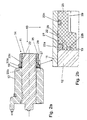
- the Fig. 1 shows an electromagnet 10 in cross section in a side view.
- an armature 13 is arranged in a cylindrical tube tube 11, an armature 13 is arranged.
- the magnetic body 12 is mounted on the tube tube 11 and the magnetic body 12, all of which are essential for an electromagnet 10, but in connection with the present invention Invention not further explained components of an electromagnet 10 has.
- the magnetic body 12 has been in the embodiment of Fig. 1 attached to the tube tube 11 and is held on this in the sliding seat.
- the upper, in Fig. 1 The right end of the electromagnet 10 forms a fastening nut 20, which has an internal thread 15 which is screwed to the compressed with the tube tube 11 magnetic core 16.
- the fastening nut 20 serves as a means 14 for fastening the magnetic body 12 on the tube tube 11.
- This compound is improved by screwing the mounting nut 20 with the magnetic core 16, wherein the fastening nut 20 presses the magnet body 12 with the tube tube 11.
- the magnetic body 12 is in electrical connection with the tube tube 11. Due to the fact that the magnetic body 12 is applied only in sliding fit on the tube tube 11, there is the possibility that these two components of the electromagnet 10 during operation, which is associated with experience with vibrations to solve each other. With the release of magnetic body 12 and tube tube 11 and the existing between these two components electrical connection is interrupted and it can then no adequate grounding of the electromagnet 10 and the tube tube 11 and the magnetic body 12 are more guaranteed.
- Electromagnet 10 shown an electrically conductive element 17, on the one hand touches the outer surface 18 of the Tubusrohrs 11 and on the other hand, the surface 19 of the magnetic body 12 and here ensures an electrical connection.
- the electrically conductive element 17 is formed in the embodiment as a partial ring which surrounds the tube tube 11 in regions. In the cross section of the ring whose structure is recognizable. These has a first arc 20 b, which causes a certain bias of the electrically conductive element 17 with respect to the surface 19 of the magnetic body 12.
- the ring Aligned to the tube tube 11, the ring has a second arc 20a, which also causes a bias of the electrically conductive element 17 here.
- the electrically conductive element 17 is integrated in the exemplary embodiment in the fastening nut 20.
- the seal 22a is placed on the electrically conductive element 17 and thereby pre-deformed in the direction of the fastening nut body.
- the arches 20a and 20b bulged so that they protrude from the recess or groove in the mounting nut 20 and are aligned with the tube tube 11 on the one hand and the magnetic body 12.
- the electrically conductive element 17 is not formed in the embodiment as a completely circumferential ring 27, but as the tube tube 11 only along a portion of the circumference comprehensive sub-ring.
- the electrically conductive element is also be forming the electrically conductive element as the tube tube 11 completely enclosing ring 27 or as a disc.
- a plurality of electrically conductive elements 17 in the fastening nut 20 which are designed, for example, as ring sections.
- the two ends of the electrically conductive element 17 formed as arcs 20a, 20b contact the tube tube 11 and the magnetic body 12.
- the magnetic body 12 is contacted by the first arc 20b of the electrically conductive element 17 extending radially with respect to the electromagnet 10, while the second Arc 20a, the tube tube 11 contacted in the axial direction.
- the joint 23 between the upper end of the magnetic body 12 and the tube tube 11 inserted therein additionally seals the seal 22a used in the fastening nut 20 for holding the electrically conductive element 17 and prevents the penetration of moisture or the like.
- the fastening nut 20 additionally has two further seals 22b, 22c, which are sunk into the corresponding receiving grooves 24 in the fastening nut 20 associated with the electrically conductive element 17.
- the seals 22b, 22c have a total of the same length as the electrically conductive element 17, which is also arranged in the fastening nut 20.
- the electrically conductive element 17 may be formed as a connecting means.
- the electrically conductive element 17 is then formed as a clip or bracket, or as a disc or ring.
- the electrically conductive element 17 is formed, for example, as a ring having a projection for engagement in the tube tube 11.
- the tube tube 11 in turn has in this case a circumferential annular groove, a bead or other recess 30 or depression, in which a projection on the electrically conductive element 17 is inserted, glued, welded or soldered.
- the thus fixed to the tube tube 11 electrically conductive element 17 is bent afterwards in the direction of the magnetic body 12 or deformed in any other way and thereby applied to the surface 19 of the magnetic body 12.
- a means 14 for attachment of magnetic body 12 and tube tube 11 a circumferential, staggered with an electrically conductive material rubber seal on the tube tube 11 set up, which is then deformed.
- This rubber seal has conductive particles, such as carbon particles. Of course, there is also the possibility that the rubber seal has only a conductive coating.
- Fig. 2a shows a schematic cross section through a further side view of an electromagnet 10 according to the invention.
- This also has a tube tube 11, on which a magnetic body 12 has been placed.
- the magnetic body 12 is fixed here in a press fit on the tube tube 11.
- the means 14 for Attachment of the magnetic body 12 on the tube tube 11 is in the embodiment of Fig. 2a formed as a cap 25 which is attached to the protruding from the magnetic body 12 end of the tube tube 11 and is also fixed here in a press fit.
- a ring 27 is provided with a double-L-shaped profile in the embodiment. This is especially in Fig. 2b particularly clear.
- the ring 27 is integrated into the cap 25 and here in a trained according to the profile shape of the ring 27 shoulder 22 attached.
- the ring 27 drags along the outer surface 18 of the Tubusrohrs 11 and contacted in the axial direction of the Tubusrohr 11.
- the second end of the ring 27 or ring profile is after complete placement of the cap 25 the tube tube 11 is applied to the cap 25 facing surface 19 of the magnetic body 12.
- a determination and permanent securing of the cap 25 takes place in that the ring 27 is inserted into a gap between the tube tube 11 and the inner peripheral surface of the cap 25 and thus clamped relative to the tube tube 11.
- a sealing ring 22a inserted in the inner profile of the ring 27 is provided here, which clamps the ring 27 with the cap 25.
- two additional recesses are provided in the cap 25, in the further sealing rings 22c, 22b are used. These sealing rings 22b, c are on the one hand on the outer surface 18 of the Tubusrohrs 11 and the other on the surface 19 of the magnetic body 12 and seal the contact space.
- Fig. 2b is already related to Fig. 2a described embodiment, reproduced in part. Shown here is the in Fig. 2a with a frame marked section in an enlarged view. Here, in particular, the shape and the profile of the ring 27 can be seen as a double-L.
- the cap 25, which is also shown in fragmentary form, has on its outer peripheral surface in addition to a non-slip coating 29, which simplifies the placement of the cap 25 on the tube tube 11 and improved.
- the Fig. 3a shows a plan view of an embodiment of the electromagnet 10 according to the invention. Also visible here is the tube tube 11, which is arranged centrally in a magnetic body 12. The magnetic body 12 has been pushed during assembly on the tube tube 11 and fixed in this press fit. In order to secure a permanent connection between the magnetic body 12 and tube tube 11, arranged on the upper surface 19 of the magnetic body 12 as a bracket 32 means 14 is arranged for attachment, on the one hand fixed to the magnetic body 12, for example, soldered, welded, glued and on the other hand the tube tube 11, which has a special recess 30 for this purpose, is used.
- the clip 32 in the Fig.
- the clamp 32 can already be arranged in the production of the magnetic body 12 at this. However, there is also the possibility that a subsequent arrangement takes place. For this purpose, a recess or the like can be provided in the magnetic body 12 or in its surface 19, into which the clamp 32 is inserted.
- the clip 32 In the course of placing the magnetic body 12 on the Tubusrohr 11, the clip 32 is slightly deformed and then locks with the projection or the blade 34 disposed thereon in an annular groove-like recess 30 in the tube tube 11, here later or already in the production of Tubusrohrs 11th can be introduced and secures the magnetic body 12 against slipping or slipping of Tubusrohr 11.
- the bracket 32 is wholly or partially formed of an electrically conductive material. It is accomplished via the bracket 32, a radial contacting of the magnetic body 12 and a radial contacting of the tube tube 11. Depending on the shape of the clip 32 may, if this example, in the axial direction of the tube tube 11 bent further projections, an axial contacting of the tube Tubus be performed.
- Fig. 4a a further plan view of a preferred embodiment of the electromagnet 10 according to the invention is shown.
- This also has a tube tube 11 which is connected to a magnetic body 12.
- a means 14 for fixing a in the sectional view of Fig. 4b clearly visible snap ring 36 is provided, which is inserted into a ringnutartige recess 30 in the tube tube 11.
- To mount the electromagnet 10 of the snap ring 36 is bent over the Tubus tube 11 striped and then solved so that it jumps into the recess 30 in the tube tube 11.
- the protrusions 37 provided on the snap ring 36 serve on the one hand to bend the snap ring 36 or to engage a corresponding tool or pliers, on the other hand these protrusions 37 also improve the electrical contacting of the magnetic body 12 and the tube tube 11, since these are in the radial direction on the Magnet body 12 abut.
- 3a, 3b, 4a and 4b illustrated embodiments of the electromagnet 10 come without additional means 14 for attachment, such as fastening nuts 20 or caps 25 from.
- the determination or securing of the magnetic body 12 on the tube tube 11 and the production of an electrical connection between these magnetic components is only on the additional elements bracket 32, as in Fig. 3a represented, or snap ring 36, as in Fig. 4a, 4b represented, accomplished.
- This embodiment of the electromagnet 10 according to the invention thus proves to be particularly cost-effective to manufacture, since on the one hand a few, cost-effective components are used, and on the other hand, the assembly effort is significantly reduced due to the easy on or add elements.
- connection is thus carried out with the least possible effort, but still provides a reliable and stable connection of magnetic body 12 and tube tube 11 and a durable and durable, as flexible and flexible electrical connection of the components tube tube 11 and magnetic body 12. Also becomes so too under load sufficient electrical contact and thus grounding of these electromagnets 10 ensured.
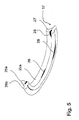
- Fig. 5 shows a perspective sectional view of an integrally formed in a seal 22a electrically conductive element 17.
- This electrically conductive element 17 is designed here as a ring 27, which has on the one hand radially and the other axially to the tube tube 11 extending portions 28.
- the regions 28 which extend radially to the tube tube 11 contact the tube tube 11, while the regions 28 formed axially to the tube tube 11 contact the magnetic body 12 and thus ensure electrical contacting of these two components of the electromagnet 10 via the ring 27.
- the ring 27 is completely received in the embodiment in a seal 22 a.
- the electrically conductive element 17 In the manufacture of the electrically conductive element this is encapsulated or foamed by a sealant, such as a rubber compound or other sealing material and is almost completely integrated into the seal 22a before. Only the regions 28 break through or project through the sealing body. It is thus protected by the in Fig. 5 illustrated embodiment of the electrically conductive element 17 reaches a maximum possible sealing of the element, since the seal 22a has two sealing beads 26a, b, which can be used for example in corresponding recesses or groove-shaped depressions in the means 14 for attachment and cause an additional seal here. The electrically conductive element 17 is thus optimally protected against corrosion and nevertheless ensures a satisfactory electrical contact between the tube tube 11 and the magnetic body 12. A possible further embodiment of the in Fig.
- electrically conductive element 17 provides that the electrically conductive element 17 is completely surrounded by a sealing material and only when placing and clamping the electrically conductive element 17 on the tube tube 11 and the magnetic body 12 by means of possibly sharp-edged projections 37 breaks through the sealant and then, on the one hand, the tube tube 11, on the other hand contacted the magnetic body 12.
Abstract
Description
Die Erfindung bezieht sich auf einen Elektromagnet mit einem Magnetkörper, der mit einem Tubusrohr verbunden ist, wobei Mittel zur Befestigung des Magnetkörpers am Tubusrohr vorgesehen sind und die Mittel wenigstens ein einerseits das Tubusrohr, andererseits den Magnetkörper kontaktierendes, elektrisch leitendes Element zur elektrischen verbindung von Tubusrohr und Magnetkörper aufweisen.The invention relates to an electromagnet with a magnetic body, which is connected to a Tubusrohr, wherein means for fixing the magnetic body are provided on Tubusrohr and the means at least one on the one hand the Tubusrohr, on the other hand, the magnetic body contacting, electrically conductive element for electrical connection of Tubusrohr and magnetic body.
Elektromagnete mit einem Tubusrohr und einem daran angeordneten Magnetkörper sind bekannt. Zur Verbindung von Magnetkörper und Tubusrohr wird der Magnetkörper auf das Tubusrohr aufgesteckt, aufgeschoben oder aufgepresst und so mehr oder weniger dauerhaft mit dem Tubusrohr verbunden. Das Tubusrohr dient dabei als Führung von einem Magnetanker, der durch Beaufschlagung mit elekrischem Strom bewegbar ist.Electromagnets with a tube tube and a magnetic body arranged thereon are known. For the connection of the magnetic body and Tubusrohr the magnetic body is attached to the Tubusrohr, deferred or pressed and so more or less permanently connected to the Tubusrohr. The Tubusrohr serves as a guide of a magnet armature, which is movable by application of electrical current.
Elektromagnete weisen in der Regel einen Schutzleiter auf, der so angebracht wird, dass eine elektrische Verbindung zwischen den metallischen Bestandteilen des Elektromagneten und dem Erdreich hergestellt ist. Besonders wichtig ist hierbei, dass der Schutzleiter alle metallischen Bestandteile des Elektromagneten kontaktiert. Bei herkömmlichen Elektromagneten, die einen auf das Tubusrohr aufgesteckten oder aufgepressten Magnetkörper aufweisen, tritt bei lange anhaltendem Gebrauch, der nicht selten mit Vibrationen einhergeht, eine Trennung der Verbindung zwischen Tubusrohr und Magnetkörper auf. Mit dieser Trennung wird oftmals auch der Schutzleiter unterbrochen, so dass keine ausreichende Erdung des Elektromagneten mehr gegeben ist. Zudem kann, bedingt durch die Tatsache, dass sich der Magnetkörper vom Tubusrohr löst, auch eine Funktionsstörung des Elektromagneten auftreten, die im Dauereinsatz unerwünscht ist und zu Stillstandszeiten sowie zu Reparaturaufwand und damit verbundenen Kosten führt.Electromagnets typically have a protective conductor which is mounted so that an electrical connection between the metallic components of the electromagnet and the soil is made. Particularly important here is that the protective conductor contacts all metallic components of the electromagnet. In conventional electromagnets which have a magnetic body plugged or pressed onto the tube tube, a separation of the connection between the tube tube and the magnetic body occurs during long-term use, which is often accompanied by vibrations. With this separation, the protective conductor is often interrupted so that there is no longer sufficient grounding of the electromagnet. In addition, due to the fact that the magnetic body dissolves from Tubusrohr, also a malfunction of the electromagnet occur, which is undesirable in continuous use and leads to downtime and repair costs and associated costs.
Es ist Aufgabe der vorliegenden Erfindung, einen Elektromagneten mit einem Tubusrohr als Führung für einen Magnetanker und einem Magnetkörper, der mit dem Tubusrohr verbunden ist zur Verfügung zu stellen, der eine zuverlässige Verbindung zwischen Tubusrohr und Magnetkörper aufweist.It is an object of the present invention to provide an electromagnet with a tube tube as a guide for a magnet armature and a magnetic body which is connected to the Tubusrohr having a reliable connection between tube tube and magnetic body.
Erfindungsgemäß wird diese Aufgabe dadurch gelöst, dass ein Elektromagnet zur Verfügung gestellt wird, der ein Tubusrohr als Führung für einen Magnetanker und einen Magnetkörper umfasst. Beim erfindungegemäßen Elektromagneten ist, wie bereits aus dem Stand der Technik bekannt, der Magnetkörper mit dem Tubusrohr verbunden. Um eine zuverlässige Verbindung zwischen dem Tubusrohr und dem Magnetkörper zu schaffen, ist der erfindungsgemäße Elektromagnet dadurch gekennzeichnet, dass wenigstens ein Mittel zur Befestigung des Magnetkörpers am Tubusrohr vorgesehen ist. Über dieses Mittel kann eine dauerhafte Verbindung zwischen Tubusrohr und Magnetkörper hergestellt werden. Um hierbei auch sicherzustellen, dass eine Erdung des Elektromagneten, aufgrund eines ununterbrochenen elektrischen Kontakts von Magnetkörper und Tubusrohr gegeben ist und hier Ströme abgeleitet werden können, ist vorgesehen, dass das Mittel wenigstens ein elektrisch leitendes Element zur elektrischen Verbindung von Tubusrohr und Magnetkörper aufweist. Das elektrisch leitende Element kontaktiert dabei einerseits das Tubusrohr und andererseits den Magnetkörper. Das elektrisch leitende Element kontaktiert dabei metallische Flächen des Tubusrohr beziehungsweise des Magnetkörpers, so dass hier ein Strom ungehindert fließen kann.According to the invention this object is achieved in that an electromagnet is provided which comprises a tube tube as a guide for a magnet armature and a magnetic body. When erfindungegemäßen electromagnet is, as already known from the prior art, the magnetic body connected to the Tubusrohr. To make a reliable connection between To provide the Tubusrohr and the magnetic body, the electromagnet according to the invention is characterized in that at least one means for fixing the magnetic body is provided on Tubusrohr. By this means, a permanent connection between Tubusrohr and magnetic body can be made. In order to ensure that a grounding of the electromagnet, due to a continuous electrical contact of the magnetic body and Tubusrohr is given and currents can be derived here, it is provided that the means comprises at least one electrically conductive element for electrically connecting Tubusrohr and magnetic body. The electrically conductive element contacted on the one hand, the Tubusrohr and on the other hand, the magnetic body. The electrically conductive element contacts metallic surfaces of the tube tube or of the magnet body, so that a current can flow unhindered here.
Das im erfindungsgemäßen Elektromagneten zum Einsatz kommende Mittel zur Befestigung von Magnetkörper und Tubusrohr beziehungsweise zur Festlegung des Magnetkörpers am Tubusrohr kann als Mutter, Klammer, Splint, Bügel, Steckverbinder, Clip, Klemmring oder in sonstiger Art und Weise, die eine sichere und zuverlässige und vor allem dauerhafte Verbindung zwischen Magnetkörper und Tubusrohr sicherstellt, ausgeführt sein. Wird das Mittel als Mutter ausgeführt, so wird diese nach dem Aufstecken oder Aufschieben beziehungsweise Verstemmen des Magnetkörpers mit dem Tubusrohr auf das Tubusrohr, das hierzu günstigerweise ein entsprechendes Gewinde aufweist, aufgeschraubt. Alternativ hierzu besteht auch die Möglichkeit, dass der Magnetkörper ein beispielsweise angesetztes oder eingeformtes Gewinde aufweist, das mit einem entsprechenden Gegengewinde der Mutter in Eingriff gebracht wird. Dabei besteht auch die Möglichkeit, dass an der Mutter ein Gewinde angefügt ist, das somit die Mutter überragt und von einer Oberfläche der Mutter vorsteht und in einer Ausnehmung im Magnetkörper, die beispielsweise das Tubusrohr umschließt, eingeschraubt wird. Es besteht selbstverständlich auch die Möglichkeit, dass insgesamt zwei Gewinde vorgesehen sind, ein radial angeordnetes Gewinde am Tubusrohr und ein axial angeordnetes Gewinde im Magnetkörper und die Mutter entsprechende Gegengewinde aufweist und somit sowohl mit dem Tubusrohr als auch mit dem Magnetkörper verbunden beziehungsweise verschraubt werden kann.The electromagnet used according to the invention for attachment of magnetic body and tube tube or fixing the magnetic body on Tubusrohr can as nut, clamp, splint, bracket, connector, clip, clamping ring or in any other way, the safe and reliable and before Ensures all permanent connection between the magnetic body and Tubusrohr, carried out. If the agent is designed as a nut, then this is screwed after plugging or pushing or caulking of the magnetic body with the Tubusrohr on the Tubusrohr, which conveniently has a corresponding thread for this purpose. Alternatively, there is also the possibility that the magnetic body has an example applied or molded thread, which is brought into engagement with a corresponding mating thread of the nut. In this case, there is also the possibility that a thread is attached to the nut, which thus projects beyond the nut and projects from a surface of the nut and in a recess in the magnetic body, for example, the tube tube encloses, is screwed. Of course, there is also the possibility that a total of two threads are provided, a radially arranged thread on Tubusrohr and an axially disposed thread in the magnetic body and the mother has corresponding counter-thread and thus connected to both the tube tube and with the magnetic body or can be screwed.
Eine einfachere Ausgestaltung des Mittels zur Befestigung stellt die Ausführung als Klammer dar, die nach dem Zusammensetzen von Tubusrohr und Magnetkörper in einer der oben bereits genannten Vorgehensweisen auf das Tubusrohr beziehungsweise auf den Magnetkörper aufgeklemmt oder aufgesetzt wird. Auch hierbei können entsprechende Vorsprünge, Nuten oder Flansche an Tubusrohr und/oder Magnetkörper vorgesehen sein, mit denen die Klammer in Eingriff gebracht wird. Über die entsprechenden Haltemittel für die Klammer kann auch eine Festlegung der Anordnungs- oder Anbringrichtung der Klammer beziehungsweise die Position der Klammer festgelegt werden. Eine besonders einfache Verbindung zwischen Tubusrohr und Magnetkörper kann auch durch die Verwendung eines Splintes erreicht werden. Dieser Splint wird in eine, entweder im Tubusrohr oder im Magnetkörper beziehungsweise in beiden Bestandteilen des Elektromagneten vorgesehene Ausnehmung beziehungsweise Durchbrechung eingesteckt und anschließend nach Art einer Splintverbindung durch verbiegen oder Verformen des Splintes festgelegt. Das Mittel zur Befestigung kann auch als zusätzliche, mit einem Splint zusammenwirkende Kronenmutter ausgeführt werden, wobei hier dann die Möglichkeit besteht, daß entweder die Mutter oder der Splint oder beide elektrisch leitend ausgebildet sind und eine elektrische Verbindung von Tubusrohr und Magnetkörper gewährleisten.A simpler embodiment of the means for fastening represents the embodiment as a clamp, which is clamped or placed after assembling tube tube and magnetic body in one of the above-mentioned procedures on the tube tube or on the magnetic body. Again, corresponding projections, grooves or flanges may be provided on Tubusrohr and / or magnetic body with which the clip is brought into engagement. By means of the corresponding holding means for the clamp, a definition of the arrangement or attachment direction of the clamp or the position of the clamp can also be defined. A particularly simple connection between Tubusrohr and magnetic body can also be achieved by the use of a split pin. This split pin is inserted into a recess or opening provided either in the tube tube or in the magnetic body or in both components of the electromagnet and then fixed in the manner of a splint connection by bending or deforming the split pin. The means for attachment can also be designed as additional, cooperating with a splint castellated nut, in which case there is the possibility that either the mother or the splint or both are electrically conductive and ensure electrical connection of Tubusrohr and magnetic body.
Neben den bereits genannten Mitteln zur Befestigung kann das Mittel als Bügel oder als Satz von Bügeln ausgebildet werden, die beispielsweise am Tubusrohr schwenkbar angeordnet sind und in einen Vorsprung oder eine entsprechend passende Aufnahme am Magnetkörper eingreifen. Im umgekehrten Fall besteht selbstverständlich auch die Möglichkeit, dass die Bügel schwenkbar am Magnetkörper angeordnet sind und in Haltemittel am Tubusrohr eingreifen. Es kann selbstverständlich auch der Bügel so ausgebildet werden, dass dieser sowohl den Magnetkörper als auch das Tubusrohr übergreift und mit beiden Elementen verspannt wird, wobei hierbei eine Festlegung des Bügels beziehungsweise der Bügelenden bevorzugt am Magnetkörper erfolgt und das Tubusrohr durch den Bügel eingefasst, eingeschlossen oder umgriffen wird. Auch kann das Mittel beziehungsweise können die Mittel als Steckverbinder oder Steckverbindung ausgeführt werden. Hierbei ist eine klemmende Verbindung zusätzlich zu der Verstemmung oder Verspannung des Tubusrohrs mit dem Magnetkörper vorgesehen. Die Steckverbindung weist hierzu entsprechende Ausnehmungen beziehungsweise Vorsprünge auf. Die Verbindung beziehungsweise Befestigung des Magnetkörpers am Tubusrohr kann auch durch einen Clip erfolgen. Dieser stellt eine Verbindung der Eigenschaften einer Klammer und eines Bügels dar und wird einerseits mit dem Tubusrohr oder dem Magnetkörper verspannt und umschließt andererseits das Tubusrohr beziehungsweise den Magnetkörper, um hier eine zuverlässige Verbindung zwischen den beiden Bestandteilen des Elektromagneten sicherzustellen. Eine weitere Möglichkeit zur Ausführung des Mittels zur Befestigung besteht darin, dass dieses als Klemmring ausgebildet wird. Hierzu weist das Tubusrohr oder der Magnetkörper eine beispielsweise umlaufend ausgebildete Ringnut auf, in die der Klemmring eingepresst oder eingesetzt wird. Auch besteht die Möglichkeit, dass das Tubusrohr eine rinnenförmige Vertiefung nach Art einer Sicke aufweist, in die der Klemmring oder Teile des Klemmrings eingreifen beziehungsweise mit denen der Klemmring verspannt oder verklemmt wird. Die gleiche oder eine ähnliche Anordnung kann selbstverständlich auch am Magnetkörper angebracht werden. Die Verbindung zwischen Tubusrohr und Magnetkörper erfolgt dann folgendermaßen: Zunächst wird das Tubusrohr hergestellt und hier, wenn nötig, entsprechende Vertiefungen oder Vorsprünge angeordnet. Danach wird der Magnetkörper auf das Tubusrohr aufgesetzt beziehungsweise aufgeschoben und hier beispielsweise im Presssitz festgelegt. Anschließend erfolgt eine dauerhafte Festlegung des Magnetkörpers am Tubusrohr und damit der Zusammenbau des Elektromagneten durch Anordnung der Befestigungsmittel. Wird hier beispielsweise ein Klemmring vorgesehen, so wird der Klemmring zunächst auf das Tubusrohr aufgeschoben, bis der Bereich des Klemmrings die am Tubusrohr oder am Magnetkörper vorgesehene Ringnut oder sickenartige Vertiefung erreicht. Durch Einrasten oder Einschnappen des Klemmrings in diese Vertiefung, wird dieser an Tubusrohr oder Magnetkörper festgelegt. Nachfolgend erfolgt dann eine Verpressung oder Verstemmung des Klemmrings oder eines Teils davon, so dass dieser auf dem Magnetkörper beziehungsweise am Tubusrohr spielfrei anliegt und die beiden Elemente des Elektromagneten dauerhaft, zuverlässig und stabil verbindet. Die genannten Mittel zur Befestigung erlauben alle eine zuverlässige Verbindung zwischen dem Tubusrohr und dem Magnetkörper und können zudem besonders einfach und damit kostengünstig angeordnet und hergestellt werden. Um eine elektrische Verbindung von Tubusrohr und Magnetkörper sicherzustellen, wird es als günstig angesehen, wenn das Mittel zur Befestigung als elektrisch leitendes Element ausgebildet ist beziehungsweise wenn das elektrisch leitende Element mit dem Mittel zur Befestigung verbunden oder in dieses integriert ist. Eine Verbindung oder Integration des elektrisch leitenden Elementes in dem Mittel beziehungsweise mit dem Mittel kann dabei fest oder lösbar ausgebildet werden. Selbstverständlich besteht auch die Möglichkeit, dass eine feste Verbindung zwischen elektrisch leitendem Element und Mittel zur Befestigung erst durch oder beim Aufsetzen, Aufstecken, Aufschrauben oder Aufklemmen des Mittels zur Befestigung auf Tubusrohr beziehungsweise Magnetkörper erstellt wird. Darüber hinaus können die elektrisch leitenden Elemente beziehungsweise das elektrisch leitende Element bereits vorab in dem Mittel zur Befestigung integriert werden und eine elektrisch leitende Aktivierung des Elementes erst beim oder nach dem Aufschrauben, Aufklemmen, Aufsetzen, Aufstecken oder sonstigen Anordnen des Mittels am Tubusrohr beziehungsweise am Magnetkörper durchgeführt werden. Als günstig wird in diesem Zusammenhang angesehen, wenn das elektrisch leitende Element als Scheibe ausgebildet ist. Hierbei bieten sich beispielsweise Ausführungen als Federscheibe, Wellenscheibe oder Lappenscheibe an, die zum einen eine Sicherung des Befestigungsmittels und andererseits eine dauerhafte und besonders stabile elektrische Kontaktierung beziehungsweise Verbindung der Magnetelemente gewährleisten können. Die Federscheibe, als eine Ausführungsform der als elektrisch leitendes Element verwendbaren Scheibe wird dabei durch das Anbringen, Aufklemmen, Aufschrauben oder Aufstecken des wie auch immer ausgeführten Mittels zur Befestigung verformt und hierbei einerseits an das Tubusrohr und andererseits an den Magnetkörper angelegt oder angepresst, so dass hier eine elektrische Verbindung gegeben ist. Nach einem ähnlichen Prinzip funktioniert die Verwendung einer Wellen- oder Lappenscheibe, wobei bei letzterer bereits verformte Bereiche vorgesehen sind, die zum einen am Tubusrohr und zum anderen am Magnetkörper angelegt werden können, um hier die elektrische Verbindung dieser Elemente zu verbessern. Neben der Ausführung des elektrisch leitenden Elementes als Scheibe besteht auch die Möglichkeit, dieses als Ring auszuführen, der über das Tubusrohr gesteckt und am Magnetkörper angelegt wird. Auch hier kann allein durch den Ring bereits eine Festlegung des Magnetkörpers am Tubusrohr erfolgen, indem der Ring als Mittel zur Befestigung einerseits und als elektrisch leitendes Element andererseits dient. Der Ring wird dann entweder mit dem Tubusrohr oder mit dem Magnetkörper dauerhaft verbunden, beispielsweise in eine entsprechende Ausnehmung, Nut oder Furche am Tubusrohr oder Magnetkörper eingesetzt und dann mit dem Magnetkörper oder Tubusrohr verstemmt oder verpresst. Hierdurch wird auch sichergestellt, dass das elektrisch leitende Element in Grenzen flexibel bleibt und somit auf Bewegungen des Magnetkörpers am Tubusrohr beziehungsweise Verschiebungen des Tubusrohrs im Magnetkörper reagieren kann, ohne dass die elektrische Verbindung zwischen den Bestandteilen abreißt. Auch kann zur weiteren Verbesserung der elektrischen Verbindung der Ring als Zahnring oder nach Art einer Zahnscheibe ausgebildet sein. Beim Ansetzen, Aufsetzen, Aufstecken, Aufschrauben oder Aufklemmen des Mittels zur Befestigung wird durch den Ring dann eine Beschädigung der Oberfläche des Tubusrohrs oder des Magnetkörpers oder beider Bestandteile durchgeführt, da der Ring beziehungsweise die Scheibe hierzu spezielle zahnartige Vorsprünge trägt. Durch diese Beschädigung der Oberfläche wird die Kontaktfläche zwischen elektrisch leitendem Element und Tubusrohr beziehungsweise Magnetkörper geschaffen oder vergrößert und die elektrische Verbindung dadurch hergestellt oder verbessert.In addition to the means already mentioned for attachment, the means may be formed as a bracket or as a set of brackets, which are pivotally mounted, for example, on Tubusrohr and engage in a projection or a correspondingly fitting recording on the magnetic body. In the opposite case, of course, there is also the possibility that the bracket are pivotally mounted on the magnetic body and engage in retaining means on Tubusrohr. It can of course also the bracket are formed so that it overlaps both the magnetic body and the tube tube and is clamped with two elements, in which case a fixing of the bracket or the temple ends preferably takes place on the magnetic body and the Tubusrohr bordered by the bracket, enclosed or is encompassed. Also, the means or the means can be designed as a connector or plug connection. Here, a clamping connection is provided in addition to the caulking or bracing of Tubusrohrs with the magnetic body. The connector has for this purpose corresponding recesses or projections. The connection or attachment of the magnetic body on Tubusrohr can also be done by a clip. This is a combination of the properties of a clip and a bracket and is braced on the one hand with the tube tube or the magnetic body and on the other hand enclosing the Tubusrohr or the magnetic body, to ensure a reliable connection between the two components of the electromagnet. Another possibility for carrying out the means for fastening is that this is designed as a clamping ring. For this purpose, the tube tube or the magnetic body has an annular circumferential groove, for example, into which the clamping ring is pressed or inserted. There is also the possibility that the tube tube has a groove-shaped depression in the manner of a bead into which the clamping ring or parts of the clamping ring engage or with which the clamping ring is clamped or clamped. The same or a similar arrangement can of course also be attached to the magnet body. The connection between Tubusrohr and magnetic body is then as follows: First, the Tubusrohr made and here, if necessary, appropriate recesses or projections arranged. Thereafter, the magnetic body is placed or pushed onto the tube tube and fixed here for example in a press fit. Subsequently, a permanent fixing of the magnetic body takes place on the tube tube and thus the assembly of the electromagnet by arrangement of the fastening means. If a clamping ring is provided here, for example, then the clamping ring is first pushed onto the tube tube until the region of the clamping ring reaches the annular groove or bead-like depression provided on the tube tube or on the magnetic body. By snapping or snapping the clamping ring in this recess, this is set to Tubusrohr or magnetic body. Subsequently, then a compression or caulking of the clamping ring or a part thereof, so that it rests on the magnetic body or on the tube tube without play and connects the two elements of the electromagnet permanently, reliably and stably. The said means for fixing all allow a reliable connection between the tube tube and the magnetic body and can also be arranged and manufactured particularly simple and therefore cost. In order to ensure an electrical connection of Tubusrohr and magnetic body, it is considered favorable if the means for fixing is formed as an electrically conductive element or if the electrically conductive element is connected to the means for attachment or integrated into this. A connection or integration of the electrically conductive element in the means or with the means can be formed fixed or detachable. Of course, there is also the possibility that a firm connection between the electrically conductive element and means for attachment only by or when placing, plugging, screwing or clamping the means for attachment to tube tube or magnetic body is created. In addition, the electrically conductive elements or the electrically conductive element already in advance be integrated in the means for attachment and an electrically conductive activation of the element only during or after screwing, clamping, placing, plugging or otherwise arranging the means on Tubusrohr or on the magnetic body are performed. As low is considered in this context, when the electrically conductive element is formed as a disc. This offer, for example, versions as a spring washer, wave washer or disc, on the one hand can ensure a backup of the fastener and on the other hand a permanent and very stable electrical contact or connection of the magnetic elements. The spring washer, as an embodiment of the usable as electrically conductive element disc is thereby deformed by attaching, clamping, or attaching the executed whatever means for attachment and this applied on the one hand to the tube tube and on the other hand to the magnetic body or pressed so that Here is an electrical connection is given. According to a similar principle, the use of a wave or rag wheel works, in the latter already deformed areas are provided, which can be applied to the tube tube on the one hand and the other on the magnetic body, to improve the electrical connection of these elements. In addition to the design of the electrically conductive element as a disk, it is also possible to perform this as a ring, which is inserted over the tube tube and applied to the magnetic body. Here, too, a determination of the magnetic body on the tube tube can already be done by the ring alone by the ring serves as a means for attachment on the one hand and as an electrically conductive element on the other. The ring is then permanently connected to either the tube tube or the magnetic body, for example, inserted into a corresponding recess, groove or groove on Tubusrohr or magnetic body and then caulked or pressed with the magnetic body or Tubusrohr. This also ensures that the electrically conductive element remains flexible within limits and thus can react to movements of the magnetic body on the tube tube or displacements of the Tubusrohrs in the magnetic body without the electrical connection between the components breaks off. Also, to further improve the electrical connection of the ring may be formed as a toothed ring or in the manner of a toothed disc. When attaching, placing, plugging, screwing or clamping the means for attachment is then carried out by the ring damage to the surface of Tubusrohrs or the magnetic body or both components, since the ring or the disc carries this special tooth-like projections. As a result of this damage to the surface, the contact surface between the electrically conductive element and tube tube or magnetic body is created or enlarged, and the electrical connection is thereby produced or improved.
Wenn eine lösbare oder feste Anordnung des elektrisch leitenden Elementes im Mittel zur Befestigung im oder am Tubusrohr und/oder im oder am Magnetkörper vorgesehen ist, so erweist es sich als besonders vorteilhaft, wenn hier eine insbesondere nutförmig ausgebildete Ausnehmung vorgesehen ist, die zum Eingriff des elektrisch leitenden Elementes dient. Diese nutförmige Ausnehmung kann bereits bei der Herstellung des Tubusrohrs des Magnetkörpers oder des Befestigungsmittels in diesem vorgesehen werden oder nachträglich hier eingeschnitten, eingeformt, eingefräst oder in sonstiger Art und Weise eingebracht werden. So besteht beispielsweise die Möglichkeit, dass das Mittel zur Befestigung aus einem Kunststoff gebildet wird. Hierbei kann bereits bei der Herstellung, die beispielsweise in einem Spritzgussverfahren erfolgt, eine entsprechende Ausnehmung in das Werkstück integriert oder eingeplant beziehungsweise eingeformt werden. Bei dem Tubusrohr, das ebenfalls aus einem Kunststoffmaterial gebildet werden kann, kann die Ausnehmung beziehungsweise Vertiefung oder Nut auch bereits im Herstellungsprozess in das Werkstück eingebracht werden. Hier besteht jedoch selbstverständlich auch die Möglichkeit, das eine nachträgliche Einbringung der Ausnehmung erfolgt. Eine bevorzugte Ausführungsform der Erfindung sieht vor, dass das elektrisch leitende Element lösbar oder fest an oder in dem Mittel zur Befestigung beziehungsweise an dem Tubusrohr oder an dem Magnetkörper angeordnet ist. Dies bedeutet, dass das elektrisch leitende Element an einem der genannten Bestandteile des Elektromagneten vorgesehen ist und eine elektrische Verbindung nach dem Aufsetzen, Ansetzen, Aufschrauben, Aufstecken oder sonstigen Verbinden von Tubusrohr und Magnetkörper und/oder dem Festlegen des Mittels zur Befestigung durchgeführt wird. Um hier eine lösbare oder feste Verbindung von elektrisch leitendem Element und Mittel zur Befestigung beziehungsweise Tubusrohr oder Magnetkörper durchführen zu können, empfiehlt sich insbesondere eine Anordnung durch Ankleben, Anschmelzen, Anlöten, Anschweißen oder dem formschlüssigen Ein- oder Ansetzen des Elementes. Eine weitere Möglichkeit besteht im Einstemmen, also dem Herstellen einer mechanischen Verbindung. Wird das Mittel zur Befestigung, der Magnetkörper oder das Tubusrohr aus einem elektrisch nicht leitenden Material hergestellt beziehungsweise weist dieses Bereiche auf, die elektrisch nicht leitend ausgebildet sind, so sieht eine bevorzugte Ausführungsform der Erfindung vor, dass das elektrisch leitende Element in das Mittel zur Befestigung, den Magnetkörper oder das Tubusrohr beziehungsweise in Bereichen davon eingeformt vorliegt, so dass hier dennoch eine ausreichende und zuverlässige sowie sichere elektrische Kontaktierung stattfinden kann. Es besteht hier zur Einformung des elektrisch leitenden Elements die Möglichkeit, dieses beispielsweise beim Herstellungprozess des Befestigungsmittels des Magnetkörpers oder des Tubusrohrs mit in den Werkstückrohling einzuspritzen. Wird hier eine Gießform verwendet, so kann das elektrisch leitende Element selbstverständlich auch mit der Vergussmasse umgossen werden, um hierbei in das Mittel zur Befestigung, den Magnetkörper oder das Tubusrohr eingeformt zu werden. Auch besteht selbstverständlich die Möglichkeit der nachträglichen Anordnung des elektrisch leitenden Elements, indem dieses in das Mittel zur Befestigung, den Magnetkörper oder das Tubusrohr eingeschmolzen wird. Das Einschmelzen kann dabei in besonders einfacher Art und Weise dadurch erfolgen, dass das elektrisch leitende Element elektrisch beaufschlagt wird und sich dabei erhitzt. Hierüber kann gleichzeitig eine Funktionskontrolle des elektrisch leitenden Elementes durchgeführt werden. Wie bereits vorher ausgeführt, kann das elektrisch leitende Element als verformbare Scheibe oder verformbarer Ring ausgebildet werden. Daneben besteht auch die Möglichkeit, dass das elektrisch leitende Element in sonstiger weise ausgeführt wird und hierbei auch verform- oder verspannbar ausgebildet ist. Eine Kontaktierung von Magnetkörper und Tubusrohr erfolgt dann nach Verformen oder Verspannen des elektrisch leitenden Elementes. Im Zuge des Verformen oder Verspannens des elektrisch leitenden Elementes kann auch ein Eingriff des elektrisch leitenden Elementes in den Magnetkörper und/oder das Tubusrohr stattfinden, so dass hier entweder erst durch den Eingriff ein elektrischer Kontakt zu einer elektrischen Verbindung hergestellt wird oder aber durch den Eingriff die bereits bestehende elektrische Kontaktierung weiter verbessert und stabilisiert wird. Die Herstellung der elektrischen Verbindung sowie der Eingriff des elektrisch leitenden Elementes in den Magnetkörper und/oder das Tubusrohr kann dabei vor, während oder nach dem Verformen oder Verspannen vorgesehen sein. Dies bedeutet, dass das elektrisch leitende Element zunächst lose, das heißt im Laufsitz oder Gleitsitz auf das Tubusrohr oder den Magnetkörper aufgesetzt oder aufgebracht wird und dann, im Zuge eines Verformungs- oder Verspannungsprozesses eine Festlegung des elektrisch leitenden Elementes erfolgt. Im Zuge des Verformens oder des Verspannens des elektrisch leitenden Elementes kommt es dann zur Herstellung oder Ausbildung eines elektrischen Kontakts beziehungsweise zu dessen Verbesserung und Stabilisierung. Das elektrisch leitende Element ist in einer bevorzugten Ausführungsform der Erfindung so ausgeführt, dass eine radiale oder axiale Kontaktierung des Magnetkörpers erfolgt, wobei auch andererseits eine axiale und/oder radiale Kontaktierung des Tubusrohrs stattfindet. Selbstverständlich besteht auch die Möglichkeit, dass das elektrisch leitende Element eines der Bestandteile, das heißt den Magnetkörper oder das Tubusrohr radial kontaktiert und das den zweiten Bestandteil, das heißt, den Magnetkörper oder das Tubusrohr andererseits axial kontaktiert. Eine axiale und radiale Kontaktierung beispielsweise des Tubusrohrs kann dadurch erreicht werden, dass in diesem eine umlaufende Ringnut vorgesehen ist, indem ein Teilbereich des elektrisch leitenden Elements eingreift und ein weiterer Bereich des elektrisch leitenden Elementes dann in axialer Richtung an dem Tubusrohr oberflächenparallel beziehungsweise umfangsparallel anliegt. Bezüglich des Magnetkörpers besteht auch die Möglichkeit, dass ein Bereich des elektrisch leitenden Elementes auf einer ersten Oberfläche des Magnetkörpers aufliegt und sich radial in diese Oberfläche erstreckt, während ein zweiter Bereich koaxial zum Magnetkörper angeordnet ist und an einer weiteren Oberfläche des Magnetkörpers axial anliegt.If a detachable or fixed arrangement of the electrically conductive element is provided in the means for attachment in or on the tube tube and / or in or on the magnetic body, then it proves to be particularly advantageous if here a particular groove-shaped recess is provided, which is for engaging the electrically conductive element is used. This groove-shaped recess can already be provided in the manufacture of the tube tube of the magnetic body or the fastening means in this or subsequently cut here, molded, milled or introduced in any other way. For example, there is the possibility that the means for attachment is formed from a plastic. In this case, a corresponding recess can already be integrated into the workpiece during the production, which takes place, for example, in an injection molding process, or can be planned in or molded into it. In the tube tube, which can also be formed from a plastic material, the recess or recess or groove can also be introduced into the workpiece during the manufacturing process. Here, however, exists Of course, the possibility that a subsequent introduction of the recess takes place. A preferred embodiment of the invention provides that the electrically conductive element is detachably or fixedly arranged on or in the means for fastening or on the tube tube or on the magnetic body. This means that the electrically conductive element is provided on one of said components of the electromagnet and an electrical connection is made after placing, attaching, screwing, plugging or otherwise connecting the tube tube and magnetic body and / or fixing the means for fastening. In order to perform a detachable or fixed connection of electrically conductive element and means for attachment or tube tube or magnetic body here, in particular, an arrangement by gluing, melting, soldering, welding or the positive insertion or attachment of the element is particularly recommended. Another possibility is in the caulking, so the establishment of a mechanical connection. If the means for fastening, the magnetic body or the tube tube made of an electrically non-conductive material or has this areas, which are electrically non-conductive, so provides a preferred embodiment of the invention, that the electrically conductive element in the means for attachment , the magnet body or the tube tube or is formed in areas thereof, so that here nevertheless a sufficient and reliable and secure electrical contact can take place. Here, for the purpose of forming the electrically conductive element, it is possible to inject it into the workpiece blank, for example during the production process of the fastening means of the magnetic body or of the tube tube. If a casting mold is used here, the electrically conductive element can, of course, also be encapsulated with the potting compound in order to be molded into the means for fastening, the magnetic body or the tube tube. Of course, there is also the possibility of subsequent arrangement of the electrically conductive element by this is melted into the means for fixing, the magnetic body or the tube tube. The melting can take place in a particularly simple manner in that the electrically conductive element is electrically charged and thereby heated. This can be carried out at the same time a functional check of the electrically conductive element. As stated previously, the electrically conductive element can be formed as a deformable disk or deformable ring. In addition, there is also the possibility that the electrically conductive element is executed in any other way and in this case is formed deformable or braced. A contacting of the magnetic body and Tubusrohr then takes place after deformation or distortion of the electrically conductive element. In the course of deforming or bracing the electrically conductive element, an engagement of the electrically conductive element in the magnetic body and / or the tube tube take place, so that here either by the engagement of an electrical contact is made to an electrical connection or by the intervention the existing electrical contact is further improved and stabilized. The preparation of the electrical connection and the engagement of the electrically conductive element in the magnetic body and / or the tube tube can be provided before, during or after the deformation or distortion. This means that the electrically conductive element is first loosely, that is placed or applied to the barrel tube or the magnetic body in the running seat or sliding fit and then, in the course of a deformation or bracing process, a determination of the electrically conductive element. In the course of deforming or straining the electrically conductive element, it then comes to the production or training of an electrical contact or to its improvement and stabilization. The electrically conductive element is designed in a preferred embodiment of the invention that a radial or axial contacting of the magnetic body takes place, wherein on the other hand takes place an axial and / or radial contacting of the Tubusrohrs. Of course, there is also the possibility that the electrically conductive element of one of the components, that is, the magnetic body or the Tubusrohr radially contacted and the other part, that is, the magnetic body or the Tubusrohr axially contacted on the other hand. Axial and radial contacting, for example, of the tube tube can be achieved by providing a circumferential annular groove therein by engaging a portion of the electrically conductive element and then abutting a further region of the electrically conductive element in the axial direction on the tube tube in parallel to the surface or parallel to the circumference. With respect to the magnetic body, there is also the possibility that a region of the electrically conductive element rests on a first surface of the magnetic body and extends radially into this surface, while a second region is arranged coaxially to the magnetic body and abuts axially on a further surface of the magnetic body.
Erfindungsgemäß ist auch vorgesehen, dass das insbesondere als Scheibe, Ring oder Klammer ausgebildete elektrisch leitende Element beziehungsweise das Mittel zur Befestigung Schneiden, Grate oder Schnittkanten aufweist, und somit eine Kontaktierungsfläche an dem Magnetkörper und dem Tubusrohr beim Einsetzen, Ansetzen, Aufsetzen, Aufklemmen, Verspannen oder Verstemmen selbständig herstellt.According to the invention, it is also provided that the electrically conductive element or the means for fastening formed in particular as a disk, ring or clamp comprises cutting edges, ridges or cut edges, and thus a contacting surface on the magnet body and the tube tube during insertion, attachment, placement, clamping, bracing or caulking independently produces.
Hierbei ist vorgesehen, dass die Schneiden durch Schnittkanten in das Material des Magnetkörpers und/oder des Tubusrohres eingreifen, und hier eine Oberflächenschicht abtragen und dauerhaft im Material des Magnetkörpers bzw. des Tubusrohres festgelegt werden. Das elektrisch leitende Element wird dabei beispielsweise mit dem Magnetkörper und dem Tubusrohr verzahnt bzw. krallt sich in diesem fest und reißt dabei bereichsweise die Oberfläche des Tubusrohres und/oder des Magnetkörpers auf, wobei eine blanke Kontaktfläche geschaffen oder vergrößert und die dauerhafte Leitfähigkeit gesichert wird.In this case, it is provided that the cutting edges engage in the material of the magnetic body and / or the tube tube by cutting edges, and here ablate a surface layer and are permanently fixed in the material of the magnetic body or of the tube tube. The electrically conductive element is interlocked, for example, with the magnetic body and the tube Tubus or clings in this firmly and thereby partially ruptures the surface of Tubusrohres and / or the magnetic body, creating or enlarging a bare contact surface and the permanent conductivity is ensured.
Im Interesse einer Materialersparnis bei der Herstellung des elektrisch leitenden Elementes kann dieses zum einen als Scheibe oder Ring hergestellt werden und die Ringstärke bzw. die Scheibendicke weitgehend reduziert werden, so dass diese nur wenige Millimeter bis Zehntel-Millimeter mißt. Die Scheibe oder der Ring können auch als Folie ausgebildet werden. Eine weitere Ausführungsform besteht darin, dass die Scheibe oder der Ring am Innen- beziehungsweise Außenumfang angeordnete radiale Ausbrechungen aufweist. Die Ausbrechungen sind dann als materialfreier Raum der Scheibe oder des Rings zu verstehen. Zwischen den Ausbrechungen verbleiben Reste des Scheiben- oder Ringkörpers, so dass die Scheibe oder der Ring letztlich nach Art eines Zahnringes mit Vorsprüngen am Außen- sowie Innenumfang ausgebildet ist. Um nun eine zuverlässige und stabile elektrische Verbindung zwischen dem Tubusrohr und dem Magnetkörper sicherstellen zu können, kann hier vorgesehen werden, dass die verbleibenden Reste des Ringkörpers im Wechsel in Richtung des Tubusrohrs bzw. des Magnetkörpers oder radial bzw. axial dazu ausgerichtet verformt, insbesondere verbogen werden und einerseits das Tubusrohr sowie andererseits den Magnetkörper kontaktieren.In the interest of saving material in the manufacture of the electrically conductive element this can be made as a disc or ring and the ring thickness or the thickness largely reduced so that it measures only a few millimeters to tenths of a millimeter. The disc or the ring can also be formed as a film. Another embodiment is that the disc or the ring has arranged on the inner or outer circumference radial Ausbrechungen. The breaks are then to be understood as a material-free space of the disc or ring. Remains of the disc or ring body remain between the breaks, so that the disc or the ring is ultimately formed in the manner of a toothed ring with projections on the outer and inner circumference. In order to be able to ensure a reliable and stable electrical connection between the tube tube and the magnet body, it can be provided here that the remaining remainders of the annular body are deformed, in particular bent, in alternation in the direction of the tube tube or the magnetic body or radially or axially aligned therewith and on the one hand contact the Tubusrohr and on the other hand, the magnetic body.
Da das elektrisch leitende Element dauernd stromführend ausgebildet ist, besteht hier die Möglichkeit, dass sich Korossion bildet. Um dies zu verhindern, sieht eine bevorzugte Ausführungsform des erfindungsgemäßen Elektromagneten vor, dass wenigstens eine das elektrisch leitende Element einschließende Dichtung vorgesehen ist.Since the electrically conductive element is designed to be permanently current-carrying, there is the possibility here that corosion forms. In order to prevent this, a preferred embodiment of the electromagnet according to the invention provides that at least one seal enclosing the electrically conductive element is provided.
Das elektrisch leitende Element kann dabei beispielsweise zwischen wenigstens zwei in axialer Richtung des Tubusrohrs angeordneten Dichtelementen angeordnet werden. Beim Zusammenbau bzw. bei der Bildung des Elektromagneten wird zunächst der Magnetkörper auf das Tubusrohr aufgeschoben oder aufgesteckt und an diesem bereits im Laufsitz oder Preßsitz festgelegt. Als nächstes wird eine erste Dichtung, beispielsweise ein Dichtring oder eine Dichtlippe oder Dichtscheibe, auf das Tubusrohr aufgeschoben, wonach dann das Aufsetzen, Aufschieben, Aufstemmen, Aufklemmen oder Aufschrauben des elektrisch leitenden Elements erfolgt. Hernach wird eine zweite Dichtung, diese kann wiederum als Scheibe, Ring, Lippe oder in sonstiger geeignet erscheinender Art und Weise ausgebildet sein, auf das Tubusrohr aufgeschoben, womit das elektrisch leitende Element zwischen zwei in axialer Richtung des Tubusrohr angeordneter Dichtelemente angeordnet wird. Alternativ oder zusätzlich besteht selbstverständlich auch die Möglichkeit, dass das elektrisch leitende Element in die Dichtung eingeformt oder eingespritzt ist, das heißt, im wesentlichen in die Dichtung integriert vorliegt. Hierbei kann eine vollständige Umschließung des elektrisch leitenden Elementes durch das Material der Dichtung bzw. durch die Dichtung selbst vorgesehen werden. Ist dies der Fall, so durchbricht das elektrisch leitende Element die Dichtung wenigstens abschnittsweise in radialer und axialer Richtung und kontaktiert das Tubusrohr und den Magnetkörper. Bevorzugt erfolgt ein Durchbrechen oder Durchstoßen der Dichtung erst beim Verformen oder Verspannen des elektrisch leitenden Elements. Hierbei ist vorgesehen, daß das elektrisch leitende Element vollständig von Dichtmaterial umgeben ist und so beispielsweise in nicht verbautem Zustand Form und Aussehen eines Dichtrings oder einer Dichtscheibe aufweist. Nach dem Aufsetzen des Elements auf dem Tubusrohr beziehungsweise nach Anordnen im Mittel zur Befestigung und nach dem Festlegen im erfindungsgemäßen Elektromagneten wird im Zuge der Festlegung das Dichtmaterial von dem im Inneren angeordneten elektrisch leitenden Element wenigstens abschnittsweise sowohl radial als auch axial durchbrochen und somit eine Kontaktierung des Tubusrohrs und des Magnetkörpers hergestellt. Um hier eine zufriedenstellende Durchbrechung vorzunehmen, weist das elektrisch leitende Element günstigerweise entsprechende Schneiden, Grate oder Vorsprünge auf, die in der Lage sind, durch das elastische Material der Dichtung zu dringen. Es besteht auch die Möglichkeit, dass beispielsweise bei der Verwendung eines Rings oder einer Scheibe auf den Oberflächen der Scheibe oder des Rings ein Dichtmaterial aufgeklebt, aufgespritzt, aufgeschweißt oder in sonstiger Art und Weise angeordnet wird und so das elektrisch leitende Element bereits mit Dichtungen versehen im Elektromagneten angeordenet werden kann. Auch hier besteht die Möglichkeit, dass das elektrisch leitende Element die Dichtung nur bereichsweise durchbricht und so eine nur bereichsweise elektrische Kontaktierung über das elektrisch leitende Element durchgeführt wird. Eine bevorzugte Ausführungsform des im erfindungsgemäßen Elektromagneten einsetzbaren elektrisch leitenden Elementes sieht vor, dass das elektrisch leitende Element Eingriffsmittel, und hier beispielsweise Schneiden, vorspringende Grate oder Schnittkanten aufweist, die eine Verletzung der Oberfläche des Magentkörpers und/oder des Tubusrohres durchführen, um hier die elektrische Kontaktierung herzustellen beziehungsweise zu verbessern. Aufgrund dieses Eingriffes in die Oberfläche des Magnetkörpers beziehungsweise des Tubusrohres wird jedoch eine korrosionsschützende Oxidschicht, die sich bei entsprechender Behandlung auf den Oberflächen bildet, verletzt beziehungsweise entfernt, so dass sich hier insbesondere an den Angriffspunkten beziehungsweise den Kontaktflächen der Schneiden, Grate oder Schnittkanten Korrosionspunkte bilden. Um einen praktisch luftdichten Abschluss des elektrisch leitenden Elementes gegenüber der umgebenden Atmosphäre zu erreichen, ist in einer bevorzugten Ausführungsform des Elektromagneten die Anordnung von Dichtungen im Mittel zur Befestigung vorgesehen, wobei die hier angeordneten Dichtungen vom elektrisch leitenden Element beabstandet angebracht sind. Vorgesehen ist hierbei eine erste Dichtung, die axial am Tubusrohr anliegt und eine zweite Dichtung, die radial am Magnetkörper abdichtet. Zwischen diesen beiden Dichtungen, die beispielsweise in entsprechenden Ausnehmungen oder Nuten im Mittel zur Befestigung eingelegt oder eingebracht, beispielsweise eingespritzt oder eingeformt sein können, befindet sich dann das elektrisch leitende Element und wird durch die Dichtungen, die beispielsweise als Dichtring, Dichtstreifen, Dichtmasse oder Dichtband ausgebildet sein können, gegenüber eindringender Feuchtigkeit geschützt. Die Dichtungen sind im Mittel zur Befestigung beabstandet zum elektrisch leitenden Element angeordnet, so dass hier zu keiner Zeit die Gefahr besteht, dass eine Verletzung der Dichtungen durch das teilweise scharfkantig ausgebildete elektrisch leitende Element erfolgt.The electrically conductive element can, for example, between at least two arranged in the axial direction of the Tubusrohrs sealing elements are arranged. When assembling or in the formation of the electromagnet, the magnetic body is first pushed onto the tube tube or plugged and fixed to this already in the running seat or press fit. Next, a first seal, such as a sealing ring or a sealing lip or gasket, is pushed onto the tube tube, after which then placing, pushing, chiselling, clamping or screwing the electrically conductive element takes place. Thereafter, a second seal, which in turn may be formed as a disc, ring, lip or in any other suitable manner, pushed onto the tube tube, whereby the electrically conductive element between two arranged in the axial direction of the tube tube sealing elements is arranged. Alternatively or additionally, of course, there is also the possibility that the electrically conductive element is molded or injected into the seal, that is, is substantially integrated in the seal. In this case, a complete enclosure of the electrically conductive element can be provided by the material of the seal or by the seal itself. If this is the case, then the electrically conductive element breaks through the seal at least in sections in the radial and axial direction and contacts the tube tube and the magnet body. Preferably, a breakthrough or puncturing of the seal takes place only during deformation or distortion of the electrically conductive element. It is provided that the electrically conductive element is completely surrounded by sealing material and thus has, for example, in unassembled state shape and appearance of a sealing ring or a sealing washer. After placement of the element on the Tubusrohr or after arranging in the means for attachment and after setting in the electromagnet according to the invention, the sealing material of the internally disposed in the interior electrically conductive element at least partially broken both radially and axially in the course thus made a contact of the Tubusrohrs and the magnetic body. In order to make a satisfactory opening here, the electrically conductive element conveniently has corresponding cutting edges, ridges or protrusions capable of penetrating through the elastic material of the seal. There is also the possibility that, for example, when using a ring or a disc on the surfaces of the disc or ring, a sealing material is glued, sprayed, welded or arranged in any other way and so already provided the electrically conductive element with seals in Electromagnet can be arranged. Again, there is the possibility that the electrically conductive element breaks through the seal only partially and so only a partial electrical contact is made via the electrically conductive element. A preferred embodiment of the insertable in the electromagnet according to the invention electrically conductive element provides that the electrically conductive element engaging means, and here, for example, cutting, protruding ridges or cut edges that perform a violation of the surface of the stomach body and / or Tubusrohres to here the electrical Establish contact or improve. Due to this engagement in the surface of the magnetic body or of the tubular tube, however, a corrosion-protecting oxide layer which forms with appropriate treatment on the surfaces is injured or removed, so that corrosion points form here, in particular at the points of contact or the contact surfaces of the cutting edges, ridges or cut edges , In order to achieve a practically airtight seal of the electrically conductive element relative to the surrounding atmosphere, in a preferred embodiment of the electromagnet, the arrangement of seals is provided in the means for attachment, wherein the seals arranged here are spaced from the electrically conductive element. Provided here is a first Seal, which rests axially on Tubusrohr and a second seal, which seals radially on the magnetic body. Between these two seals, which may be inserted or introduced, for example, injected or molded, for example, in corresponding recesses or grooves in the means, then the electrically conductive element and is through the seals, for example, as a sealing ring, sealing strip, sealant or sealing tape may be formed, protected against moisture penetration. The seals are arranged spaced apart from the means for fixing the electrically conductive element, so that there is at no time the risk that a violation of the seals by the partially sharp-edged electrically conductive element takes place.
Günstigerweise sind die mit dem erfindungsgemäßen Elektromagneten verwendbaren Dichtungen als O-Ringe, Dichtbänder, Dichtlippen oder Dichtscheiben ausgebildet. Bei der - wie oben bereits genannten Anordnung von zwei Dichtungen ober- und unterseits des elektrisch leitenden Elements - besteht auch die Möglichkeit, dass wenigstens zwei Dichtungen einen Kontaktraum am Tubusrohr oder im Magnetkörper bilden, in dem das elektrisch leitende Element angeordnet ist. Die Dichtungen begrenzen dann den Kontaktraum nach zwei Seiten hin. Die Dichtungen müssen dem elektrisch leitenden Element auch nicht unmittelbar am Elektromagneten, das heißt am Tubusrohr und/oder am Magnetkörper zugeordnet angeordnet sein. Wichtig ist, dass die Dichtungen das Eindringen von Flüssigkeit oder von Luft verhindern, so dass keine Korrosion des elektrisch leitenden Elementes stattfinden kann.Conveniently, the seals used with the electromagnet according to the invention are designed as O-rings, sealing strips, sealing lips or sealing washers. In the - as already mentioned above arrangement of two seals above and below the electrically conductive element - there is also the possibility that at least two seals form a contact space on Tubusrohr or in the magnetic body in which the electrically conductive element is arranged. The seals then limit the contact space to two sides. The seals must also not be arranged directly on the electromagnet, that is to say on the tube tube and / or on the magnet body, to the electrically conductive element. It is important that the seals prevent the ingress of liquid or air, so that no corrosion of the electrically conductive element can take place.
Es besteht auch die Möglichkeit, dass das elektrisch leitende Element als sogenannter Leitgummi ausgeführt wird. Dieser Leitgummi besteht dann aus mit Kohlenstoffpartikeln gefülltem oder versetztem Gummimaterial. Das Verwenden eines Leitgummis bietet den Vorteil, dass hier eine elastische Dauerverbindung durchgeführt werden kann, die auch bei Vibration, wie diese an Elektromagneten auftritt, eine stabile und dauerhafte elektrische Verbindung zwischen Tubusrohr und Magnetkörper sicherstellen kann. Zudem übernimmt der Dichtgummi auch eine Abdichtfunktion für die Verbindungsstelle beziehungsweise -fläche von Tubusrohr und Magnetkörper.There is also the possibility that the electrically conductive element is designed as a so-called conductive rubber. This conductive rubber then consists of carbon particles filled or offset rubber material. Using a conductive rubber provides the advantage that here an elastic permanent connection can be performed, which can ensure a stable and permanent electrical connection between Tubusrohr and magnetic body even with vibration, as this occurs on electromagnets. In addition, the sealing rubber also assumes a sealing function for the connection point or area of tube tube and magnet body.
Als empfehlenswert wird auch angesehen, wenn eine unmittelbar am oder im elektrisch leitenden Element angeordnete zusätzliche Dichtung vorgesehen ist. Diese Dichtung kann dann dafür verwendet werden, das elektrisch leitende Element mit dem Mittel zur Befestigung zu befestigen, zu verbinden oder zu verspannen und gleichzeitig abzudichten. Dies erfolgt dadurch, dass sich in einer Verbindung von elektrisch leitendem Element und Mittel zur Befestigung das Dichtelement verformt und im Zuge dieser Verformung eine Verformung des elektrisch leitenden Elements durchgeführt wird, wobei dieses in das Mittel zur Befestigung eingepresst oder dauerhaft eingesetzt und festgelegt wird. Auch hier, wie bei allen anderen verwendeten Dichtungen, besteht die Möglichkeit, diese ganz oder teilweise aus Leitgummi zu bilden.It is also considered to be recommendable if an additional seal arranged directly on or in the electrically conductive element is provided. This seal can then be used to secure, connect or clamp the electrically conductive element with the means for attachment and at the same time seal. This is done by deforming the sealing element in a connection of the electrically conductive element and the fastening means and, in the course of this deformation, carrying out a deformation of the electrically conductive element, which is pressed into the fastening means or permanently inserted and fixed. Again, as with all other seals used, it is possible to form these wholly or partly of conductive rubber.
Das elektrisch leitende Element ist in einer bevorzugten Weiterbildung des erfindungsgemäßen Elektromagneten als Masseband bzw. nach Art eines Massebandes ausgebildet. Das Masseband kann dabei ein aus einem Drahtmaterial gebildetes Geflecht aufweisen aus einem Metallstreifen bzw. -band oder aus einem mit Metall versetzten Kunststoffstreifen gebildet sein. Ein erstes Ende des Massebandes ist dabei zur Festlegung am Tubusrohr vorgesehen, während ein zweites Ende des Massebandes den Magnetkörper kontaktiert. Der Bandkörper, das heißt, der die beiden Enden des Massebandes verbindende Bereich ist am oder im Mittel zur Befestigung angeordnet oder darin festgelegt beziehungsweise in dieses eingeformt.The electrically conductive element is formed in a preferred embodiment of the electromagnet according to the invention as a grounding strap or in the manner of a ground strap. In this case, the ground strap can have a braid formed from a wire material and can be formed from a metal strip or band or from a plastic strip offset with metal. A first end of the ground strap is provided for fixing to the tube tube, while a second end of the ground strap contacts the magnetic body. The band body, that is, the region connecting the two ends of the ground strap is arranged on or in the attachment means or fixed therein or molded into it.
Als günstig erweist es sich, wenn das elektrisch leitende Element als wenigstens teilweise elektrisch leitende Beschichtung des Mittels zur Befestigung ausgebildet ist. Durch die Beschichtung kann sichergestellt werden, dass eine ausreichend große Oberfläche zur elektrischen Kontaktierung zur Verfügung gestellt wird. Darüber hinaus kann die Beschichtung auch dann stabil am Mittel zur Befestigung verbleiben, wenn dieses oder diese verformt wird. Ist beispielsweise das Mittel zur Befestigung als Befestigungsmutter ausgebildet, so besteht die Möglichkeit, dass hier das Gewinde der Mutter oder deren gesamte Oberfläche mit einer elektrisch leitenden Beschichtung versehen ist. Mit dem Aufschrauben der Mutter auf das Tubusrohr beziehungsweise den Magnetkörper erfolgt dann die elektrische Verbindung. Es besteht selbstverständlich auch die Möglichkeit, dass das Mittel zur Befestigung aus einem elektrisch leitenden Material gebildet ist und eine Schutzbeschichtung aufweist, die beim Anordnen des Mittels zur Befestigung am Tubusrohr und/oder dem Magnetkörper beschädigt beziehungsweise entfernt wird und eine elektrische Kontaktierung erst dann stattfindet. Daneben besteht auch die Möglichkeit, dass das Mittel zur Befestigung beispielsweise aus einem elektrisch nicht leitenden Grundmaterial gebildet ist, das mit leitfähigem Material beaufschlagt ist, in das beispielsweise leitende Partikel, wie Metallpartikel oder Späne beziehungsweise Graphit- oder Kohlenstoffstaub eingemischt wurde. Hierüber wird dann eine elektrische Leitfähigkeit des Mittels zur Befestigung erreicht, die später zur elektrischen Verbindung von Tubusrohr und Magnetkörper Verwendung findet.It proves to be advantageous if the electrically conductive element is designed as an at least partially electrically conductive coating of the means for attachment. The coating can ensure that a sufficiently large surface is provided for electrical contacting. Moreover, the coating can remain stably attached to the fixing means even if it is deformed. If, for example, the fastening means is designed as a fastening nut, it is possible that here the thread of the nut or its entire surface is provided with an electrically conductive coating. By screwing the nut on the Tubusrohr or the magnetic body is then the electrical connection. Of course, there is also the possibility that the means for attachment of an electrically conductive material is formed and having a protective coating, which is damaged or removed when arranging the means for attachment to the tube tube and / or the magnetic body and an electrical contact takes place only then. In addition, there is also the possibility that the means for attachment, for example, formed from an electrically non-conductive base material, which is acted upon with conductive material, in the example, conductive particles such as metal particles or chips or graphite or carbon dust was mixed. This then an electrical conductivity of the means for attachment is achieved, which is later used for the electrical connection of Tubusrohr and magnetic body.
Die Erfindung stellt auch einen Elektromagneten zur Verfügung, der ein das Tubusrohr und den Magnetkörper umschließendes Gehäuse aufweist. Um hier eine Kontaktierung des Tubusrohrs und des Magnetkörpers sicherzustellen, besteht einerseits die Möglichkeit, das elektrisch leitende Element in das Gehäuse einzufügen und über das Mittel zur Befestigung eine Festlegung von Tubusrohr, Gehäuse und Magnetkörper durchzuführen. Im Zuge dieser Festlegung erfolgt dann die elektrische Kontaktierung beziehungsweise Verbindung von Magnetkörper und Tubusrohr. Darüber hinaus besteht auch die Möglichkeit, das elektrisch leitende Element so auszubilden, dass eine elektrische Verbindung von Gehäuse, Magnetkörper und Tubusrohr über das elektrisch leitende Element stattfinden kann. Hierbei ist die Verwendung aller vorgenannter Ausführungsformen des elektrisch leitenden Elements beziehungsweise des Mittels zur Befestigung möglich, wobei lediglich noch das Gehäuse von diesen Bestandteilen des Elektromagneten mit umfasst beziehungsweise mit festgelegt oder kontaktiert wird.The invention also provides an electromagnet having a housing enclosing the tube tube and the magnetic body. In order to ensure a contacting of the Tubusrohrs and the magnetic body, on the one hand there is the possibility to insert the electrically conductive element in the housing and on the means for fixing a determination of Tubusrohr, housing and magnetic body perform. In the course of this determination is then made the electrical contact or connection of the magnetic body and Tubusrohr. In addition, it is also possible, the electrically conductive element in such a way that an electrical connection of housing, magnetic body and Tubusrohr can take place via the electrically conductive element. Here, the use of all the aforementioned embodiments of the electrically conductive element or the means for attachment is possible, wherein only the housing of these components of the electromagnet is also included or fixed with or contacted.
Der erfindungsgemäße Elektromagnet eignet sich bevorzugt für eine Betriebsspannung im Niederspannungsbereich, das heißt, zwischen 12 V und 400 V wird. Als günstig wird angesehen, wenn eine Spannung zwischen 12 V und 230 V, zwischen 12 V und 48 V oder zwischen 12 V und 35 V am Elektromagneten anliegt. Selbstverständlich besteht die Möglichkeit, auch Betriebsspannungen die höher oder niedriger liegen, das heißt in einem Bereich unter 12 V beziehungsweise über 400 V am Elektromagneten anzulegen. Das elektrisch leitende Element muss dann so ausgebildet sein, dass auch diese Spannungen aufgenommen werden können.The electromagnet according to the invention is preferably suitable for an operating voltage in the low-voltage range, that is, between 12 V and 400 V. It is considered favorable when a voltage between 12 V and 230 V, between 12 V and 48 V or between 12 V and 35 V is applied to the electromagnet. Of course, it is also possible to apply operating voltages which are higher or lower, that is to say in a range below 12 V or above 400 V at the electromagnet. The electrically conductive element must then be designed so that these voltages can be absorbed.
Es versteht sich, dass die vorstehend genannten und nachstehend noch zu erläuternden Merkmale nicht nur in der jeweiligen angegebenen Kombination sondern auch in anderen Kombinationen denkbar und verwend- beziehungsweise einsetzbar sind.It is understood that the features mentioned above and those yet to be explained not only in the respective combination specified but also in other combinations conceivable and can be used or used.
Die Erfindung wird im folgenden anhand von Ausführungsbeispielen unter Bezugnahme auf die zugehörigen Zeichnungen näher erläutert. Es zeigen:
- Fig. 1
- einen schematischen Querschnitt einer Seitenansicht eines erfin-
- Fig. 2a
- dungsgemäßen Elektromagneten; einen schematischen Querschnitt einer weiteren Seitenansicht eines erfindungsgemäßen Elektromagneten;
- Fig. 2b
- eine Detaildarstellung eines Aus- schnitts des elektrisch leitenden Elementes in einer Einbauposition an einem Elektromagneten;
- Fig. 3a
- eine Draufsicht auf eine Ausfüh- rungsform des erfindungsgemäßen Elektromagneten
- Fig. 3b
- eine Ausschnittsdarstellung aus der Draufsicht der
Fig. 3b ; - Fig. 4a
- eine weitere Draufsicht auf eine bevorzugte Ausführungsform des er- findungsgemäßen Elektromagneten;
- Fig. 4b
- eine Ausschnittsdarstellung aus der Draufsicht der
Fig. 4a ; und - Fig. 5
- perspektivische Schnittdarstellung eines in eine Dichtung eingeform- ten elektrisch leitenden Elemen- tes.
- Fig. 1
- 1 is a schematic cross section of a side view of an invention
- Fig. 2a
- to the invention electromagnet; a schematic cross-section of another side view of an electromagnet according to the invention;
- Fig. 2b
- a detailed representation of a section of the electrically conductive element in an installed position on an electromagnet;
- Fig. 3a
- a plan view of an embodiment of the inventive electromagnet
- Fig. 3b
- a sectional view of the top view of
Fig. 3b ; - Fig. 4a
- a further plan view of a preferred embodiment of the inventive solenoid;
- Fig. 4b
- a sectional view of the top view of
Fig. 4a ; and - Fig. 5
- perspective sectional view of a formed in a gasket electrically conductive ele- tes.
Die
Selbstverständlich besteht auch die Möglichkeit, dass keine Befestigungsmutter 20 verwendet wird, um die Verbindung zwischen Magnetkörper 12 und Tubusrohr 11 zu sichern, beziehungsweise zu verbessern. Vielmehr kann stattdessen auch das elektrisch leitende Element 17 als Verbindungsmittel ausgebildet sein. Das elektrisch leitende Element 17 ist dann als Klammer oder Bügel, oder aber auch als Scheibe oder Ring ausgebildet. In dieser Ausführungsform, das heißt in der Ausführungsform ohne Befestigungsmutter 20 beziehungsweise sonstiges Mittel 14 zum Befestigen, wird das elektrisch leitende Element 17 beispielsweise als Ring ausgebildet, der einen Vorsprung zum Eingriff in das Tubusrohr 11 aufweist. Das Tubusrohr 11 wiederum verfügt in diesem Fall über eine umlaufende Ringnut, eine Sicke oder eine sonstige Ausnehmung 30 oder Vertiefung, in die ein vorsprung am elektrisch leitenden Element 17 eingesetzt, eingeklebt, eingeschweißt oder eingelötet wird. Das somit am Tubusrohr 11 festgelegte elektrisch leitende Element 17 wird hernach in Richtung des Magnetkörpers 12 verbogen oder in sonstiger Weise verformt und dabei an der Oberfläche 19 des Magnetkörpers 12 angelegt. Nach einer abschließenden Verpressung oder Verstemmung des elektrisch leitenden Elementes 17 wird eine dauerhafte und belastbare Verbindung von Tubusrohr 11 und Magnetkörper 12 durchgeführt. Daneben besteht auch die Möglichkeit, als Mittel 14 zur Befestigung von Magnetkörper 12 und Tubusrohr 11 eine umlaufende, mit einem elektrisch leitfähigen Material versetzte Gummidichtung auf das Tubusrohr 11 aufzusetzen, die dann verformt wird.Of course, there is also the possibility that no
Diese Gummidichtung verfügt über leitfähige Partikel, beispielsweise Kohlenstoffpartikel. Selbstverständlich besteht auch die Möglichkeit, dass die Gummidichtung nur eine leitfähige Beschichtung aufweist.This rubber seal has conductive particles, such as carbon particles. Of course, there is also the possibility that the rubber seal has only a conductive coating.
In
Die
In
Die jetzt mit der Anmeldung und später eingereichten Ansprüche sind Versuche zur Formulierung ohne Präjudiz für die Erzielung weitergehenden Schutzes.The claims now filed with the application and later are attempts to formulate without prejudice to the attainment of further protection.
Sollte sich hier bei näherer Prüfung, insbesondere auch des einschlägigen Standes der Technik, ergeben, daß das eine oder andere Merkmal für das Ziel der Erfindung zwar günstig, nicht aber entscheidend wichtig ist, so wird selbstverständlich schon jetzt eine Formulierung angestrebt, die ein solches Merkmal, insbesondere im Hauptanspruch, nicht mehr aufweist.If, on closer examination, in particular also of the relevant prior art, it appears that one or the other feature is beneficial for the purpose of the invention, but not of decisive importance, it is of course already desired to formulate such a feature , in particular in the main claim, no longer having.
Es ist weiter zu beachten, daß die in den verschiedenen Ausführungsformen beschriebenen und in den Figuren gezeigten Ausgestaltungen und Varianten der Erfindung beliebig untereinander kombinierbar sind. Dabei sind einzelne oder mehrere Merkmale beliebig gegeneinander austauschbar. Diese Merkmalskombinationen sind ebenso mit offenbart.It should further be noted that the embodiments and variants of the invention described in the various embodiments and shown in the figures can be combined with one another as desired. Here, one or more features are arbitrarily interchangeable. These feature combinations are also disclosed with.
Die in den abhängigen Ansprüchen angeführten Rückbeziehungen weisen auf die weitere Ausbildung des Gegenstandes des Hauptanspruches durch die Merkmale des jeweiligen Unteranspruches ein. Jedoch sind diese nicht als ein Verzicht auf die Erzielung eines selbständigen, gegenständlichen Schutzes für die Merkmale der rückbezogenen Unteransprüche zu verstehen.The references cited in the dependent claims indicate the further development of the subject matter of the main claim by the features of the respective subclaim. However, these are not to be understood as a waiver of obtaining independent, objective protection for the features of the dependent claims.
Merkmale, die bislang nur in der Beschreibung offenbart wurden, können im Laufe des Verfahrens als von erfindungswesentlicher Bedeutung, zum Beispiel zur Abgrenzung vom Stand der Technik beansprucht werden.Features that have hitherto been disclosed only in the description may be claimed in the course of the method as of essential importance to the invention, for example to distinguish from the prior art.
Merkmale, die nur in der Beschreibung offenbart wurden, oder auch Einzelmerkmale aus Ansprüchen, die eine Mehrzahl von Merkmalen umfassen, können jederzeit zur Abgrenzung vom Stande der Technik in den ersten Anspruch übernommen werden, und zwar auch dann, wenn solche Merkmale im Zusammenhang mit anderen Merkmalen erwähnt wurden beziehungsweise im Zusammenhang mit anderen Merkmalen besonders günstige Ergebnisse erreichen.Features which have been disclosed only in the description, or also individual features of claims comprising a plurality of features, may at any time be included in the first claim for distinction from the prior art, even if such features are associated with others Characteristics were mentioned or achieve particularly favorable results in connection with other features.
Claims (15)
Applications Claiming Priority (1)
| Application Number | Priority Date | Filing Date | Title |
|---|---|---|---|
| DE102009041604A DE102009041604A1 (en) | 2009-09-17 | 2009-09-17 | electromagnet |
Publications (3)
| Publication Number | Publication Date |
|---|---|
| EP2299457A2 true EP2299457A2 (en) | 2011-03-23 |
| EP2299457A3 EP2299457A3 (en) | 2014-10-01 |
| EP2299457B1 EP2299457B1 (en) | 2018-11-14 |
Family
ID=42991055
Family Applications (1)
| Application Number | Title | Priority Date | Filing Date |
|---|---|---|---|
| EP10009439.0A Active EP2299457B1 (en) | 2009-09-17 | 2010-09-10 | Electromagnet |
Country Status (4)
| Country | Link |
|---|---|
| US (1) | US8410879B2 (en) |
| EP (1) | EP2299457B1 (en) |
| JP (1) | JP5812589B2 (en) |
| DE (1) | DE102009041604A1 (en) |
Cited By (2)
| Publication number | Priority date | Publication date | Assignee | Title |
|---|---|---|---|---|
| WO2014114457A1 (en) * | 2013-01-28 | 2014-07-31 | Thomas Magnete Gmbh | Device actuated by an electromagnet, comprising an encapsulated threaded connection |
| EP3312853A1 (en) * | 2016-10-21 | 2018-04-25 | SVM Schultz Verwaltungs-GmbH & Co. KG | Electromagnet |
Families Citing this family (1)
| Publication number | Priority date | Publication date | Assignee | Title |
|---|---|---|---|---|
| DE102012214624A1 (en) * | 2012-08-17 | 2014-02-20 | Robert Bosch Gmbh | Pole tube for an actuator device |
Family Cites Families (21)
| Publication number | Priority date | Publication date | Assignee | Title |
|---|---|---|---|---|
| US1226748A (en) * | 1915-07-01 | 1917-05-22 | Sears B Condit Jr | Solenoid. |
| US2931617A (en) * | 1955-05-11 | 1960-04-05 | Minnesota Honeywell Regulator | Damped solenoid valve operator |
| US4055823A (en) * | 1975-05-22 | 1977-10-25 | Danfoss A/S | Electromagnetic valve assembly means |
| US4790345A (en) * | 1987-03-17 | 1988-12-13 | Parker-Hannifin Corporation | Proportional valve |
| JPH0614415Y2 (en) * | 1987-08-17 | 1994-04-13 | 本田技研工業株式会社 | Electromagnetic actuator |
| DE3737777A1 (en) * | 1987-11-06 | 1989-05-18 | Elektroteile Gmbh | Solenoid valve |
| JPH02145369U (en) * | 1989-05-11 | 1990-12-10 | ||
| US5208570A (en) * | 1992-04-06 | 1993-05-04 | Caterpillar Inc. | Solenoid construction and method for making same |
| JP3324366B2 (en) * | 1994-11-22 | 2002-09-17 | 株式会社デンソー | Magnetic switch for starter |
| JP3079465B2 (en) * | 1995-10-23 | 2000-08-21 | 油研工業株式会社 | Electromagnet device |
| US5915591A (en) * | 1997-09-10 | 1999-06-29 | Illinois Tool Works Inc. | Electric solenoid valve for hot melt adhesive and method therefor |
| US5875922A (en) * | 1997-10-10 | 1999-03-02 | Nordson Corporation | Apparatus for dispensing an adhesive |
| DE19751113A1 (en) * | 1997-11-18 | 1999-05-20 | Nass Magnet Gmbh | magnetic valve |
| DE19907732B4 (en) * | 1999-02-23 | 2008-08-28 | Bosch Rexroth Aktiengesellschaft | Hydraulic solenoid valve |
| US6257445B1 (en) * | 2000-03-23 | 2001-07-10 | Nordson Corporation | Electrically operated viscous fluid dispensing apparatus and method |
| JP4042963B2 (en) * | 2002-10-04 | 2008-02-06 | 株式会社ケーヒン | Electromagnetic device |
| DE102004035501A1 (en) * | 2004-07-22 | 2006-02-09 | Bosch Rexroth Aktiengesellschaft | Solenoid with adjustable magnetic force |
| DE102006010913B3 (en) * | 2006-03-09 | 2007-06-21 | Hydac Electronic Gmbh | Operating device for implementing control functions, has stretching finger, tapered surface, extension and disk spring plate unit that are switchable between locking condition and release condition |
| DE102007005434A1 (en) * | 2007-01-30 | 2008-07-31 | Svm Schultz Verwaltungs-Gmbh & Co. Kg | Double acting electromagnetic actuator for hydraulic and pneumatic applications, has anchor arranged in coil with two permanent magnets in axial direction and anchor is supported in pole tube arranged in coil |
| US7975982B2 (en) * | 2008-09-03 | 2011-07-12 | Defond Components Limited | Electromagnetic valve |
| DE102008064604B4 (en) * | 2008-11-12 | 2018-09-20 | Svm Schultz Verwaltungs-Gmbh & Co. Kg | Electromagnetically actuated fluid valve |
-
2009
- 2009-09-17 DE DE102009041604A patent/DE102009041604A1/en not_active Withdrawn
-
2010
- 2010-09-10 EP EP10009439.0A patent/EP2299457B1/en active Active
- 2010-09-17 US US12/923,381 patent/US8410879B2/en active Active
- 2010-09-17 JP JP2010208888A patent/JP5812589B2/en not_active Expired - Fee Related
Non-Patent Citations (1)
| Title |
|---|
| None |
Cited By (3)
| Publication number | Priority date | Publication date | Assignee | Title |
|---|---|---|---|---|
| WO2014114457A1 (en) * | 2013-01-28 | 2014-07-31 | Thomas Magnete Gmbh | Device actuated by an electromagnet, comprising an encapsulated threaded connection |
| US9435385B2 (en) | 2013-01-28 | 2016-09-06 | Thomas Magnete Gmbh | Device which is operated by an electromagnet and has an encapsulated threaded connection |
| EP3312853A1 (en) * | 2016-10-21 | 2018-04-25 | SVM Schultz Verwaltungs-GmbH & Co. KG | Electromagnet |
Also Published As
| Publication number | Publication date |
|---|---|
| JP2011066422A (en) | 2011-03-31 |
| EP2299457B1 (en) | 2018-11-14 |
| DE102009041604A1 (en) | 2011-03-24 |
| JP5812589B2 (en) | 2015-11-17 |
| US20110063056A1 (en) | 2011-03-17 |
| US8410879B2 (en) | 2013-04-02 |
| EP2299457A3 (en) | 2014-10-01 |
Similar Documents
| Publication | Publication Date | Title |
|---|---|---|
| EP1741163B1 (en) | Method for the electrically conductive contacting of an essentially rigid electrically conductive outer conductor of a coaxial cable | |
| EP2299457B1 (en) | Electromagnet | |
| DE102008025428B4 (en) | Method for manufacturing an electrical connection device | |
| EP1859515B1 (en) | Socket for a lamp | |
| DE4428699B4 (en) | Electrical connection arrangement | |
| DE102010009805B4 (en) | jumper | |
| EP3292592B1 (en) | Battery terminal and method for producing a battery terminal | |
| EP2894357B1 (en) | Clip nut, fastening assembly and a method for producing a clip nut | |
| DE3909548C2 (en) | ||
| DE102009050564A1 (en) | Attachment for electromagnets | |
| DE4008117C2 (en) | ||
| DE102012215872A1 (en) | Failover element for assembly of captive screw at cable shoe for fastening electric conductors at electric contact, has disk-shaped holding element for retaining head of screw, and tongue radial outwardly extending at holding element | |
| DE1615861A1 (en) | Adjustable resistance | |
| DE102011002831B4 (en) | Connecting arrangement between two electrically conductive components of a structure, in particular on a motor vehicle | |
| DE102010035571A1 (en) | Electric switch | |
| DE102020007697A1 (en) | Fuse and method of making a fuse | |
| DE10103008A1 (en) | Screw connecting device for vehicle starter motor cable shoe, has tight conductive collar coaxial with locking nut | |
| DE102021004718A1 (en) | Fuse and method of making a fuse | |
| WO2022233504A1 (en) | Fuse, and method for manufacturing a fuse | |
| DE1923629C (en) | Cable termination for insulated power cables | |
| DE202015004891U1 (en) | Mass attachment device for a motor vehicle | |
| DE102013217977A1 (en) | Arrangement for producing an electrical contact, electric drive, and method | |
| WO2019001994A1 (en) | Method for producing an electric component and electric component | |
| DE4440942A1 (en) | Electrical connector and brush-holder for rotary electrical machine | |
| DE102011076511A1 (en) | Solar module connection box, solar module, manufacturing method |
Legal Events
| Date | Code | Title | Description |
|---|---|---|---|
| PUAI | Public reference made under article 153(3) epc to a published international application that has entered the european phase |
Free format text: ORIGINAL CODE: 0009012 |
|
| AK | Designated contracting states |
Kind code of ref document: A2 Designated state(s): AL AT BE BG CH CY CZ DE DK EE ES FI FR GB GR HR HU IE IS IT LI LT LU LV MC MK MT NL NO PL PT RO SE SI SK SM TR |
|
| AX | Request for extension of the european patent |
Extension state: BA ME RS |
|
| PUAL | Search report despatched |
Free format text: ORIGINAL CODE: 0009013 |
|
| AK | Designated contracting states |
Kind code of ref document: A3 Designated state(s): AL AT BE BG CH CY CZ DE DK EE ES FI FR GB GR HR HU IE IS IT LI LT LU LV MC MK MT NL NO PL PT RO SE SI SK SM TR |
|
| AX | Request for extension of the european patent |
Extension state: BA ME RS |
|
| RIC1 | Information provided on ipc code assigned before grant |
Ipc: H01F 7/16 20060101ALI20140826BHEP Ipc: H01F 7/127 20060101AFI20140826BHEP |
|
| 17P | Request for examination filed |
Effective date: 20150331 |
|
| RBV | Designated contracting states (corrected) |
Designated state(s): AL AT BE BG CH CY CZ DE DK EE ES FI FR GB GR HR HU IE IS IT LI LT LU LV MC MK MT NL NO PL PT RO SE SI SK SM TR |
|
| 17Q | First examination report despatched |
Effective date: 20160921 |
|
| STAA | Information on the status of an ep patent application or granted ep patent |
Free format text: STATUS: EXAMINATION IS IN PROGRESS |
|
| GRAP | Despatch of communication of intention to grant a patent |
Free format text: ORIGINAL CODE: EPIDOSNIGR1 |
|
| STAA | Information on the status of an ep patent application or granted ep patent |
Free format text: STATUS: GRANT OF PATENT IS INTENDED |
|
| INTG | Intention to grant announced |
Effective date: 20180528 |
|
| GRAS | Grant fee paid |
Free format text: ORIGINAL CODE: EPIDOSNIGR3 |
|
| GRAA | (expected) grant |
Free format text: ORIGINAL CODE: 0009210 |
|
| STAA | Information on the status of an ep patent application or granted ep patent |
Free format text: STATUS: THE PATENT HAS BEEN GRANTED |
|
| AK | Designated contracting states |
Kind code of ref document: B1 Designated state(s): AL AT BE BG CH CY CZ DE DK EE ES FI FR GB GR HR HU IE IS IT LI LT LU LV MC MK MT NL NO PL PT RO SE SI SK SM TR |
|
| REG | Reference to a national code |
Ref country code: GB Ref legal event code: FG4D Free format text: NOT ENGLISH |
|
| REG | Reference to a national code |
Ref country code: CH Ref legal event code: EP Ref country code: AT Ref legal event code: REF Ref document number: 1065819 Country of ref document: AT Kind code of ref document: T Effective date: 20181115 |
|
| REG | Reference to a national code |
Ref country code: DE Ref legal event code: R096 Ref document number: 502010015555 Country of ref document: DE |
|
| REG | Reference to a national code |
Ref country code: IE Ref legal event code: FG4D Free format text: LANGUAGE OF EP DOCUMENT: GERMAN |
|
| REG | Reference to a national code |
Ref country code: NL Ref legal event code: MP Effective date: 20181114 |
|
| REG | Reference to a national code |
Ref country code: LT Ref legal event code: MG4D |
|
| PG25 | Lapsed in a contracting state [announced via postgrant information from national office to epo] |
Ref country code: IS Free format text: LAPSE BECAUSE OF FAILURE TO SUBMIT A TRANSLATION OF THE DESCRIPTION OR TO PAY THE FEE WITHIN THE PRESCRIBED TIME-LIMIT Effective date: 20190314 Ref country code: BG Free format text: LAPSE BECAUSE OF FAILURE TO SUBMIT A TRANSLATION OF THE DESCRIPTION OR TO PAY THE FEE WITHIN THE PRESCRIBED TIME-LIMIT Effective date: 20190214 Ref country code: ES Free format text: LAPSE BECAUSE OF FAILURE TO SUBMIT A TRANSLATION OF THE DESCRIPTION OR TO PAY THE FEE WITHIN THE PRESCRIBED TIME-LIMIT Effective date: 20181114 Ref country code: LT Free format text: LAPSE BECAUSE OF FAILURE TO SUBMIT A TRANSLATION OF THE DESCRIPTION OR TO PAY THE FEE WITHIN THE PRESCRIBED TIME-LIMIT Effective date: 20181114 Ref country code: NO Free format text: LAPSE BECAUSE OF FAILURE TO SUBMIT A TRANSLATION OF THE DESCRIPTION OR TO PAY THE FEE WITHIN THE PRESCRIBED TIME-LIMIT Effective date: 20190214 Ref country code: HR Free format text: LAPSE BECAUSE OF FAILURE TO SUBMIT A TRANSLATION OF THE DESCRIPTION OR TO PAY THE FEE WITHIN THE PRESCRIBED TIME-LIMIT Effective date: 20181114 Ref country code: LV Free format text: LAPSE BECAUSE OF FAILURE TO SUBMIT A TRANSLATION OF THE DESCRIPTION OR TO PAY THE FEE WITHIN THE PRESCRIBED TIME-LIMIT Effective date: 20181114 Ref country code: FI Free format text: LAPSE BECAUSE OF FAILURE TO SUBMIT A TRANSLATION OF THE DESCRIPTION OR TO PAY THE FEE WITHIN THE PRESCRIBED TIME-LIMIT Effective date: 20181114 |
|
| PG25 | Lapsed in a contracting state [announced via postgrant information from national office to epo] |
Ref country code: SE Free format text: LAPSE BECAUSE OF FAILURE TO SUBMIT A TRANSLATION OF THE DESCRIPTION OR TO PAY THE FEE WITHIN THE PRESCRIBED TIME-LIMIT Effective date: 20181114 Ref country code: AL Free format text: LAPSE BECAUSE OF FAILURE TO SUBMIT A TRANSLATION OF THE DESCRIPTION OR TO PAY THE FEE WITHIN THE PRESCRIBED TIME-LIMIT Effective date: 20181114 Ref country code: GR Free format text: LAPSE BECAUSE OF FAILURE TO SUBMIT A TRANSLATION OF THE DESCRIPTION OR TO PAY THE FEE WITHIN THE PRESCRIBED TIME-LIMIT Effective date: 20190215 Ref country code: PT Free format text: LAPSE BECAUSE OF FAILURE TO SUBMIT A TRANSLATION OF THE DESCRIPTION OR TO PAY THE FEE WITHIN THE PRESCRIBED TIME-LIMIT Effective date: 20190314 Ref country code: NL Free format text: LAPSE BECAUSE OF FAILURE TO SUBMIT A TRANSLATION OF THE DESCRIPTION OR TO PAY THE FEE WITHIN THE PRESCRIBED TIME-LIMIT Effective date: 20181114 |
|
| PG25 | Lapsed in a contracting state [announced via postgrant information from national office to epo] |
Ref country code: DK Free format text: LAPSE BECAUSE OF FAILURE TO SUBMIT A TRANSLATION OF THE DESCRIPTION OR TO PAY THE FEE WITHIN THE PRESCRIBED TIME-LIMIT Effective date: 20181114 Ref country code: PL Free format text: LAPSE BECAUSE OF FAILURE TO SUBMIT A TRANSLATION OF THE DESCRIPTION OR TO PAY THE FEE WITHIN THE PRESCRIBED TIME-LIMIT Effective date: 20181114 Ref country code: CZ Free format text: LAPSE BECAUSE OF FAILURE TO SUBMIT A TRANSLATION OF THE DESCRIPTION OR TO PAY THE FEE WITHIN THE PRESCRIBED TIME-LIMIT Effective date: 20181114 |
|
| REG | Reference to a national code |
Ref country code: DE Ref legal event code: R097 Ref document number: 502010015555 Country of ref document: DE |
|
| PG25 | Lapsed in a contracting state [announced via postgrant information from national office to epo] |
Ref country code: EE Free format text: LAPSE BECAUSE OF FAILURE TO SUBMIT A TRANSLATION OF THE DESCRIPTION OR TO PAY THE FEE WITHIN THE PRESCRIBED TIME-LIMIT Effective date: 20181114 Ref country code: SM Free format text: LAPSE BECAUSE OF FAILURE TO SUBMIT A TRANSLATION OF THE DESCRIPTION OR TO PAY THE FEE WITHIN THE PRESCRIBED TIME-LIMIT Effective date: 20181114 Ref country code: SK Free format text: LAPSE BECAUSE OF FAILURE TO SUBMIT A TRANSLATION OF THE DESCRIPTION OR TO PAY THE FEE WITHIN THE PRESCRIBED TIME-LIMIT Effective date: 20181114 Ref country code: RO Free format text: LAPSE BECAUSE OF FAILURE TO SUBMIT A TRANSLATION OF THE DESCRIPTION OR TO PAY THE FEE WITHIN THE PRESCRIBED TIME-LIMIT Effective date: 20181114 |
|
| REG | Reference to a national code |
Ref country code: DE Ref legal event code: R082 Ref document number: 502010015555 Country of ref document: DE Representative=s name: PATENTANWAELTE OLBRICHT, BUCHHOLD, KEULERTZ PA, DE |
|
| PLBE | No opposition filed within time limit |
Free format text: ORIGINAL CODE: 0009261 |
|
| STAA | Information on the status of an ep patent application or granted ep patent |
Free format text: STATUS: NO OPPOSITION FILED WITHIN TIME LIMIT |
|
| 26N | No opposition filed |
Effective date: 20190815 |
|
| PG25 | Lapsed in a contracting state [announced via postgrant information from national office to epo] |
Ref country code: SI Free format text: LAPSE BECAUSE OF FAILURE TO SUBMIT A TRANSLATION OF THE DESCRIPTION OR TO PAY THE FEE WITHIN THE PRESCRIBED TIME-LIMIT Effective date: 20181114 |
|
| PG25 | Lapsed in a contracting state [announced via postgrant information from national office to epo] |
Ref country code: TR Free format text: LAPSE BECAUSE OF FAILURE TO SUBMIT A TRANSLATION OF THE DESCRIPTION OR TO PAY THE FEE WITHIN THE PRESCRIBED TIME-LIMIT Effective date: 20181114 |
|
| PG25 | Lapsed in a contracting state [announced via postgrant information from national office to epo] |
Ref country code: MC Free format text: LAPSE BECAUSE OF FAILURE TO SUBMIT A TRANSLATION OF THE DESCRIPTION OR TO PAY THE FEE WITHIN THE PRESCRIBED TIME-LIMIT Effective date: 20181114 |
|
| REG | Reference to a national code |
Ref country code: CH Ref legal event code: PL |
|
| PG25 | Lapsed in a contracting state [announced via postgrant information from national office to epo] |
Ref country code: IE Free format text: LAPSE BECAUSE OF NON-PAYMENT OF DUE FEES Effective date: 20190910 Ref country code: LI Free format text: LAPSE BECAUSE OF NON-PAYMENT OF DUE FEES Effective date: 20190930 Ref country code: LU Free format text: LAPSE BECAUSE OF NON-PAYMENT OF DUE FEES Effective date: 20190910 Ref country code: CH Free format text: LAPSE BECAUSE OF NON-PAYMENT OF DUE FEES Effective date: 20190930 |
|
| REG | Reference to a national code |
Ref country code: BE Ref legal event code: MM Effective date: 20190930 |
|
| PG25 | Lapsed in a contracting state [announced via postgrant information from national office to epo] |
Ref country code: BE Free format text: LAPSE BECAUSE OF NON-PAYMENT OF DUE FEES Effective date: 20190930 |
|
| GBPC | Gb: european patent ceased through non-payment of renewal fee |
Effective date: 20190910 |
|
| PG25 | Lapsed in a contracting state [announced via postgrant information from national office to epo] |
Ref country code: FR Free format text: LAPSE BECAUSE OF NON-PAYMENT OF DUE FEES Effective date: 20190930 Ref country code: GB Free format text: LAPSE BECAUSE OF NON-PAYMENT OF DUE FEES Effective date: 20190910 |
|
| REG | Reference to a national code |
Ref country code: AT Ref legal event code: MM01 Ref document number: 1065819 Country of ref document: AT Kind code of ref document: T Effective date: 20190910 |
|
| PG25 | Lapsed in a contracting state [announced via postgrant information from national office to epo] |
Ref country code: AT Free format text: LAPSE BECAUSE OF NON-PAYMENT OF DUE FEES Effective date: 20190910 |
|
| PG25 | Lapsed in a contracting state [announced via postgrant information from national office to epo] |
Ref country code: CY Free format text: LAPSE BECAUSE OF FAILURE TO SUBMIT A TRANSLATION OF THE DESCRIPTION OR TO PAY THE FEE WITHIN THE PRESCRIBED TIME-LIMIT Effective date: 20181114 |
|
| PG25 | Lapsed in a contracting state [announced via postgrant information from national office to epo] |
Ref country code: HU Free format text: LAPSE BECAUSE OF FAILURE TO SUBMIT A TRANSLATION OF THE DESCRIPTION OR TO PAY THE FEE WITHIN THE PRESCRIBED TIME-LIMIT; INVALID AB INITIO Effective date: 20100910 Ref country code: MT Free format text: LAPSE BECAUSE OF FAILURE TO SUBMIT A TRANSLATION OF THE DESCRIPTION OR TO PAY THE FEE WITHIN THE PRESCRIBED TIME-LIMIT Effective date: 20181114 |
|
| PG25 | Lapsed in a contracting state [announced via postgrant information from national office to epo] |
Ref country code: MK Free format text: LAPSE BECAUSE OF FAILURE TO SUBMIT A TRANSLATION OF THE DESCRIPTION OR TO PAY THE FEE WITHIN THE PRESCRIBED TIME-LIMIT Effective date: 20181114 |
|
| REG | Reference to a national code |
Ref country code: DE Ref legal event code: R082 Ref document number: 502010015555 Country of ref document: DE Representative=s name: PATENTANWAELTE OLBRICHT, BUCHHOLD, KEULERTZ PA, DE |
|
| PGFP | Annual fee paid to national office [announced via postgrant information from national office to epo] |
Ref country code: DE Payment date: 20230930 Year of fee payment: 14 |
|
| PGFP | Annual fee paid to national office [announced via postgrant information from national office to epo] |
Ref country code: IT Payment date: 20230927 Year of fee payment: 14 |