EP2299177A1 - Combustor of a gas turbine - Google Patents
Combustor of a gas turbine Download PDFInfo
- Publication number
- EP2299177A1 EP2299177A1 EP09170877A EP09170877A EP2299177A1 EP 2299177 A1 EP2299177 A1 EP 2299177A1 EP 09170877 A EP09170877 A EP 09170877A EP 09170877 A EP09170877 A EP 09170877A EP 2299177 A1 EP2299177 A1 EP 2299177A1
- Authority
- EP
- European Patent Office
- Prior art keywords
- combustor
- hollow elements
- cover plate
- damping
- fixing
- Prior art date
- Legal status (The legal status is an assumption and is not a legal conclusion. Google has not performed a legal analysis and makes no representation as to the accuracy of the status listed.)
- Withdrawn
Links
Images


Classifications
-
- F—MECHANICAL ENGINEERING; LIGHTING; HEATING; WEAPONS; BLASTING
- F23—COMBUSTION APPARATUS; COMBUSTION PROCESSES
- F23R—GENERATING COMBUSTION PRODUCTS OF HIGH PRESSURE OR HIGH VELOCITY, e.g. GAS-TURBINE COMBUSTION CHAMBERS
- F23R3/00—Continuous combustion chambers using liquid or gaseous fuel
- F23R3/002—Wall structures
-
- F—MECHANICAL ENGINEERING; LIGHTING; HEATING; WEAPONS; BLASTING
- F23—COMBUSTION APPARATUS; COMBUSTION PROCESSES
- F23M—CASINGS, LININGS, WALLS OR DOORS SPECIALLY ADAPTED FOR COMBUSTION CHAMBERS, e.g. FIREBRIDGES; DEVICES FOR DEFLECTING AIR, FLAMES OR COMBUSTION PRODUCTS IN COMBUSTION CHAMBERS; SAFETY ARRANGEMENTS SPECIALLY ADAPTED FOR COMBUSTION APPARATUS; DETAILS OF COMBUSTION CHAMBERS, NOT OTHERWISE PROVIDED FOR
- F23M20/00—Details of combustion chambers, not otherwise provided for, e.g. means for storing heat from flames
- F23M20/005—Noise absorbing means
-
- F—MECHANICAL ENGINEERING; LIGHTING; HEATING; WEAPONS; BLASTING
- F23—COMBUSTION APPARATUS; COMBUSTION PROCESSES
- F23R—GENERATING COMBUSTION PRODUCTS OF HIGH PRESSURE OR HIGH VELOCITY, e.g. GAS-TURBINE COMBUSTION CHAMBERS
- F23R2900/00—Special features of, or arrangements for continuous combustion chambers; Combustion processes therefor
- F23R2900/00014—Reducing thermo-acoustic vibrations by passive means, e.g. by Helmholtz resonators
Definitions
- the present invention relates to a combustor of a gas turbine.
- Gas turbines are known to comprise combustors wherein compressed air coming from the compressor is fed and mixed with a gaseous or liquid fuel to be then combusted.
- pressure oscillations may be generated in the combustor due to thermo acoustic instabilities; these pressure oscillations may cause structural damages or excessive wear of the gas turbine components and, in addition, a noisy operation.
- damping is achieved by passive damping structures.
- Examples of these passive damping structures are Helmholtz resonators, quarter-wave tubes, screen or perforated screech liners.
- US 7 104 065 discloses a damping arrangement for a combustor with a two-walled combustion chamber and a further outer wall defining a gastight volume connected to the inner of the combustion chamber.
- this damping arrangement is functionally separated from the other components of the combustor and, moreover, it proved difficult to incorporate it in the combustor, due to the limited space available.
- the technical aim of the present invention is therefore to provide a combustor by which the said problems of the known art are eliminated.
- an aspect of the invention is to provide a combustor in which proper cooling can be guaranteed in any operating condition, to increase its lifetime.
- Another aspect of the invention is to provide a combustor which lets the NO x emissions be controlled.
- a further aspect of the present invention is to provide a combustor in which the damping system is functionally integrated with the other components of the combustor and is also incorporated thereinto.
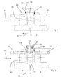
- Figure 1 shows a combustor 1 having a mixing tube 2 and a combustion chamber 3.
- the combustor 1 (i.e. its mixing tube 2 and/or combustion chamber 3 and/or front plate 2a) has at least a portion 4 comprising an inner liner 5 and an outer cover plate 6 defining with the inner liner 5 an interposed cooling chamber 7.
- any portions of the mixing tube 2 and/or combustion chamber 3 and/or front plate 2a or also all the wall of the mixing tube 2 and/or the combustion chamber 3 and/or front plate 2a may have this structure; for sake of simplicity and clarity in the following reference to the portion 4 of the combustion chamber 3 depicted in figure 3 will be made.
- Each hollow element 9 defines a damping volume 10 connected to the inner of the combustion chamber 3 via a calibrated duct 11 (in particular the length and the diameter of the duct are calibrated).
- the hollow elements 9 operate as Helmholtz dampers to damp pressure oscillations and, in addition, as they are connected to the liner 5 delimiting the hottest part of the gas turbine, they also collect heat from the liner 5 and dissipate it, transferring it to the cooling air.
- the hollow elements 9 may also have a purge hole 13 connecting the cooling chamber 7 with the damping volume 10.
- the purge hole 13 may be provided in order to increase cooling, but in other embodiments it may be absent to eliminate any air loss.
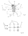
- hollow elements 9 are arranged to transfer heat to dissipate it, different embodiments for their disposition are possible.
- Figure 10 shows a first disposition with hollow elements 9 aligned along the cooling flow direction 14, and figures 3-5 show further embodiments with hollow elements 9 staggered with respect to the cooling flow direction 14; this disposition is preferred because of the larger heat transfer.
- the shape of the hollow elements 9 is chosen and optimised in accordance with the acceptable pressure drop.
- hollow elements 9 such as cylindrical shape ( figure 3 ) or elliptical shape ( figure 5 ) or airfoil type shape ( figure 4 ) or combinations thereof.
- the top wall 16 of the hollow elements 9 is separated from the cover plate 6.
- different hollow elements 9 define different damping volumes 10 and/or the hollow elements 9 may have the damping volume 10 filled with a damping material 17 that increases dissipation and switches the pressure oscillation frequency that is damped by that particular damping volume to a value different from that provided by the empty damping volume 10.
- fixing hollow elements 9f are connected to the cover plate 6 ( figures 7-9 ).
- Fixing cover elements 9f have a structure similar to that of cover elements 9, but in addition they also have components that let them be connected to the cover plate 6.
- the cover plate 6 is provided with through holes 19 in which the fixing hollow elements 9f (that are longer than hollow elements 9) are housed.
- the fixing hollow elements 9f have shoulders 20 against which the cover plate 6 rests.
- connection is achieved via threaded end portions 22 of the fixing hollow elements 9f connected to the cover plate 9 via bolts 23; naturally also different connections are possible such as brazed or welded connections.
- the fixing hollow elements 9f of figure 8 have an adjustable top wall 24.
- the adjustable top wall 24 of the fixing hollow elements 9f of figure 8 comprises a threaded cap 25 fixed into a corresponding threaded portion 26 of the fixing hollow elements 9f.
- Adjustment of the damping volume 10 lets the pressure oscillation frequency that is damped be regulated.
- the fixing hollow elements 9f of figure 9 is provided with the damping material 17.
- Provision of damping material 17 within the damping volume 10 also lets the pressure oscillation frequency that is damped be regulated.
- the mixture formed in the mixing tube 2 is combusted in the combustion chamber 3 generating hot gases G that are expanded in a turbine (not shown); in this respect reference 27 indicated the flame.
- cooling air circulates (as indicated by arrow F)
- the mixing tube 2, the combustion chamber 3 and the front plate 2a are cooled.
- the hollow elements 9, 9f project into the cooling chamber 7, the cooling air impinges them such that a very intense cooling effect is achieved.
- This structure allows a very efficient damping effect to be achieved, because the combustor is provided with a plurality of Helmholtz dampers that if needed may also be placed along the whole wall of the combustor (i.e. mixing tube 2, combustion chamber 3 and front plate 2a).
- the structure of the invention is able to damp pressure oscillations in a very wide range.
- cooling effect is very efficient, because the hollow elements 9, 9f that project into the cooling chamber 10 operate like heat exchanging fins. Cooling effect can also be increased in hollow elements 9 and/or 9f via purge holes 13.
Landscapes
- Engineering & Computer Science (AREA)
- Chemical & Material Sciences (AREA)
- Combustion & Propulsion (AREA)
- Mechanical Engineering (AREA)
- General Engineering & Computer Science (AREA)
- Turbine Rotor Nozzle Sealing (AREA)
- Gas Burners (AREA)
- Soundproofing, Sound Blocking, And Sound Damping (AREA)
Priority Applications (5)
| Application Number | Priority Date | Filing Date | Title |
|---|---|---|---|
| EP09170877A EP2299177A1 (en) | 2009-09-21 | 2009-09-21 | Combustor of a gas turbine |
| JP2012530216A JP5642186B2 (ja) | 2009-09-21 | 2010-09-15 | ガスタービンの燃焼器 |
| EP10759840.1A EP2480833B1 (en) | 2009-09-21 | 2010-09-15 | Combustor of a gas turbine |
| PCT/EP2010/063513 WO2011032959A1 (en) | 2009-09-21 | 2010-09-15 | Combustor of a gas turbine |
| US13/424,839 US8635874B2 (en) | 2009-09-21 | 2012-03-20 | Gas turbine combustor including an acoustic damper device |
Applications Claiming Priority (1)
| Application Number | Priority Date | Filing Date | Title |
|---|---|---|---|
| EP09170877A EP2299177A1 (en) | 2009-09-21 | 2009-09-21 | Combustor of a gas turbine |
Publications (1)
| Publication Number | Publication Date |
|---|---|
| EP2299177A1 true EP2299177A1 (en) | 2011-03-23 |
Family
ID=41609800
Family Applications (2)
| Application Number | Title | Priority Date | Filing Date |
|---|---|---|---|
| EP09170877A Withdrawn EP2299177A1 (en) | 2009-09-21 | 2009-09-21 | Combustor of a gas turbine |
| EP10759840.1A Active EP2480833B1 (en) | 2009-09-21 | 2010-09-15 | Combustor of a gas turbine |
Family Applications After (1)
| Application Number | Title | Priority Date | Filing Date |
|---|---|---|---|
| EP10759840.1A Active EP2480833B1 (en) | 2009-09-21 | 2010-09-15 | Combustor of a gas turbine |
Country Status (4)
| Country | Link |
|---|---|
| US (1) | US8635874B2 (ja) |
| EP (2) | EP2299177A1 (ja) |
| JP (1) | JP5642186B2 (ja) |
| WO (1) | WO2011032959A1 (ja) |
Cited By (3)
| Publication number | Priority date | Publication date | Assignee | Title |
|---|---|---|---|---|
| EP2693121A1 (en) | 2012-07-31 | 2014-02-05 | Alstom Technology Ltd | Near-wall roughness for damping devices reducing pressure oscillations in combustion systems |
| EP3240971B1 (en) | 2015-01-23 | 2020-02-12 | Siemens Aktiengesellschaft | Combustion chamber for a gas turbine engine |
| CN113757719A (zh) * | 2021-09-18 | 2021-12-07 | 北京航空航天大学 | 燃烧室燃烧振荡的控制方法及燃烧室 |
Families Citing this family (12)
| Publication number | Priority date | Publication date | Assignee | Title |
|---|---|---|---|---|
| EP2385303A1 (en) * | 2010-05-03 | 2011-11-09 | Alstom Technology Ltd | Combustion Device for a Gas Turbine |
| US9127837B2 (en) * | 2010-06-22 | 2015-09-08 | Carrier Corporation | Low pressure drop, low NOx, induced draft gas heaters |
| CH703357A1 (de) * | 2010-06-25 | 2011-12-30 | Alstom Technology Ltd | Wärmebelastetes, gekühltes bauteil. |
| WO2015112220A2 (en) * | 2013-11-04 | 2015-07-30 | United Technologies Corporation | Turbine engine combustor heat shield with one or more cooling elements |
| US10267523B2 (en) * | 2014-09-15 | 2019-04-23 | Ansaldo Energia Ip Uk Limited | Combustor dome damper system |
| EP3227611A1 (en) * | 2014-12-01 | 2017-10-11 | Siemens Aktiengesellschaft | Resonators with interchangeable metering tubes for gas turbine engines |
| US10513984B2 (en) | 2015-08-25 | 2019-12-24 | General Electric Company | System for suppressing acoustic noise within a gas turbine combustor |
| US10197275B2 (en) | 2016-05-03 | 2019-02-05 | General Electric Company | High frequency acoustic damper for combustor liners |
| US11204204B2 (en) * | 2019-03-08 | 2021-12-21 | Toyota Motor Engineering & Manufacturing North America, Inc. | Acoustic absorber with integrated heat sink |
| US11536454B2 (en) * | 2019-05-09 | 2022-12-27 | Pratt & Whitney Canada Corp. | Combustor wall assembly for gas turbine engine |
| US11174792B2 (en) | 2019-05-21 | 2021-11-16 | General Electric Company | System and method for high frequency acoustic dampers with baffles |
| US11156164B2 (en) | 2019-05-21 | 2021-10-26 | General Electric Company | System and method for high frequency accoustic dampers with caps |
Citations (10)
| Publication number | Priority date | Publication date | Assignee | Title |
|---|---|---|---|---|
| FR2570129A1 (fr) * | 1984-09-05 | 1986-03-14 | Messerschmitt Boelkow Blohm | Dispositif pour amortir les vibrations dans la chambre de combustion de moteurs-fusees a propergols liquides |
| US5373695A (en) * | 1992-11-09 | 1994-12-20 | Asea Brown Boveri Ltd. | Gas turbine combustion chamber with scavenged Helmholtz resonators |
| WO2005059441A1 (en) * | 2003-12-16 | 2005-06-30 | Ansaldo Energia S.P.A. | A system for damping thermo-acoustic instability in a combustor device for a gas turbine |
| EP1605209A1 (de) * | 2004-06-07 | 2005-12-14 | Siemens Aktiengesellschaft | Brennkammer mit einer Dämpfungseinrichtung zur Dämpfung von thermoakustischen Schwingungen |
| US20060059913A1 (en) * | 2004-09-21 | 2006-03-23 | Siemens Aktiengesellschaft | Combustion chamber for a gas turbine with at least two resonator devices |
| US7104065B2 (en) | 2001-09-07 | 2006-09-12 | Alstom Technology Ltd. | Damping arrangement for reducing combustion-chamber pulsation in a gas turbine system |
| EP1862739A2 (en) * | 2006-06-01 | 2007-12-05 | Rolls-Royce plc | Combustion chamber for a gas turbine engine |
| EP1865259A2 (de) * | 2006-06-09 | 2007-12-12 | Rolls-Royce Deutschland Ltd & Co KG | Gasturbinenbrennkammerwand für eine mager-brennende Gasturbinenbrennkammer |
| DE102006053277A1 (de) * | 2006-11-03 | 2008-05-08 | Deutsches Zentrum für Luft- und Raumfahrt e.V. | Resonatorvorrichtung und Brennkammervorrichtung |
| WO2009038611A2 (en) * | 2007-09-14 | 2009-03-26 | Siemens Energy, Inc. | Non-rectangular resonator devices providing enhanced liner cooling for combustion chamber |
Family Cites Families (11)
| Publication number | Priority date | Publication date | Assignee | Title |
|---|---|---|---|---|
| US6464489B1 (en) * | 1997-11-24 | 2002-10-15 | Alstom | Method and apparatus for controlling thermoacoustic vibrations in a combustion system |
| JP3946395B2 (ja) * | 1999-11-12 | 2007-07-18 | 株式会社東芝 | ガスタービン燃焼器 |
| US6530221B1 (en) * | 2000-09-21 | 2003-03-11 | Siemens Westinghouse Power Corporation | Modular resonators for suppressing combustion instabilities in gas turbine power plants |
| GB2390150A (en) * | 2002-06-26 | 2003-12-31 | Alstom | Reheat combustion system for a gas turbine including an accoustic screen |
| GB2396687A (en) * | 2002-12-23 | 2004-06-30 | Rolls Royce Plc | Helmholtz resonator for combustion chamber use |
| JP2005076982A (ja) * | 2003-08-29 | 2005-03-24 | Mitsubishi Heavy Ind Ltd | ガスタービン燃焼器 |
| GB0427147D0 (en) * | 2004-12-11 | 2005-01-12 | Rolls Royce Plc | Combustion chamber for a gas turbine engine |
| US7413053B2 (en) * | 2006-01-25 | 2008-08-19 | Siemens Power Generation, Inc. | Acoustic resonator with impingement cooling tubes |
| JP4981615B2 (ja) * | 2007-10-19 | 2012-07-25 | 三菱重工業株式会社 | ガスタービン |
| US8567197B2 (en) * | 2008-12-31 | 2013-10-29 | General Electric Company | Acoustic damper |
| EP2385303A1 (en) * | 2010-05-03 | 2011-11-09 | Alstom Technology Ltd | Combustion Device for a Gas Turbine |
-
2009
- 2009-09-21 EP EP09170877A patent/EP2299177A1/en not_active Withdrawn
-
2010
- 2010-09-15 JP JP2012530216A patent/JP5642186B2/ja not_active Expired - Fee Related
- 2010-09-15 EP EP10759840.1A patent/EP2480833B1/en active Active
- 2010-09-15 WO PCT/EP2010/063513 patent/WO2011032959A1/en active Application Filing
-
2012
- 2012-03-20 US US13/424,839 patent/US8635874B2/en not_active Expired - Fee Related
Patent Citations (10)
| Publication number | Priority date | Publication date | Assignee | Title |
|---|---|---|---|---|
| FR2570129A1 (fr) * | 1984-09-05 | 1986-03-14 | Messerschmitt Boelkow Blohm | Dispositif pour amortir les vibrations dans la chambre de combustion de moteurs-fusees a propergols liquides |
| US5373695A (en) * | 1992-11-09 | 1994-12-20 | Asea Brown Boveri Ltd. | Gas turbine combustion chamber with scavenged Helmholtz resonators |
| US7104065B2 (en) | 2001-09-07 | 2006-09-12 | Alstom Technology Ltd. | Damping arrangement for reducing combustion-chamber pulsation in a gas turbine system |
| WO2005059441A1 (en) * | 2003-12-16 | 2005-06-30 | Ansaldo Energia S.P.A. | A system for damping thermo-acoustic instability in a combustor device for a gas turbine |
| EP1605209A1 (de) * | 2004-06-07 | 2005-12-14 | Siemens Aktiengesellschaft | Brennkammer mit einer Dämpfungseinrichtung zur Dämpfung von thermoakustischen Schwingungen |
| US20060059913A1 (en) * | 2004-09-21 | 2006-03-23 | Siemens Aktiengesellschaft | Combustion chamber for a gas turbine with at least two resonator devices |
| EP1862739A2 (en) * | 2006-06-01 | 2007-12-05 | Rolls-Royce plc | Combustion chamber for a gas turbine engine |
| EP1865259A2 (de) * | 2006-06-09 | 2007-12-12 | Rolls-Royce Deutschland Ltd & Co KG | Gasturbinenbrennkammerwand für eine mager-brennende Gasturbinenbrennkammer |
| DE102006053277A1 (de) * | 2006-11-03 | 2008-05-08 | Deutsches Zentrum für Luft- und Raumfahrt e.V. | Resonatorvorrichtung und Brennkammervorrichtung |
| WO2009038611A2 (en) * | 2007-09-14 | 2009-03-26 | Siemens Energy, Inc. | Non-rectangular resonator devices providing enhanced liner cooling for combustion chamber |
Cited By (5)
| Publication number | Priority date | Publication date | Assignee | Title |
|---|---|---|---|---|
| EP2693121A1 (en) | 2012-07-31 | 2014-02-05 | Alstom Technology Ltd | Near-wall roughness for damping devices reducing pressure oscillations in combustion systems |
| US9261058B2 (en) | 2012-07-31 | 2016-02-16 | Alstom Technology Ltd | Near-wall roughness for damping devices reducing pressure oscillations in combustion systems |
| EP3240971B1 (en) | 2015-01-23 | 2020-02-12 | Siemens Aktiengesellschaft | Combustion chamber for a gas turbine engine |
| EP3240971B2 (en) † | 2015-01-23 | 2024-01-03 | Siemens Energy Global GmbH & Co. KG | Combustion chamber for a gas turbine engine |
| CN113757719A (zh) * | 2021-09-18 | 2021-12-07 | 北京航空航天大学 | 燃烧室燃烧振荡的控制方法及燃烧室 |
Also Published As
| Publication number | Publication date |
|---|---|
| EP2480833B1 (en) | 2018-03-21 |
| WO2011032959A1 (en) | 2011-03-24 |
| EP2480833A1 (en) | 2012-08-01 |
| US8635874B2 (en) | 2014-01-28 |
| US20120260657A1 (en) | 2012-10-18 |
| JP2013505427A (ja) | 2013-02-14 |
| JP5642186B2 (ja) | 2014-12-17 |
Similar Documents
| Publication | Publication Date | Title |
|---|---|---|
| EP2480833B1 (en) | Combustor of a gas turbine | |
| EP3022490B1 (en) | Cooling cover for gas turbine damping resonator | |
| US8516819B2 (en) | Forward-section resonator for high frequency dynamic damping | |
| KR101206891B1 (ko) | 2차 연료 전달 시스템 | |
| CN107208893B (zh) | 用于燃气涡轮发动机的燃烧室 | |
| US8943825B2 (en) | Helmholtz damper for a combustor of a gas turbine and a method for installing the helmholtz damper | |
| EP3051206B1 (en) | Sequential gas turbine combustor arrangement with a mixer and a damper | |
| US20120102963A1 (en) | Gas turbine combustor with mounting for helmholtz resonators | |
| CA2826099C (en) | Acoustic damper arrangement for a combustor | |
| US20080245337A1 (en) | System for reducing combustor dynamics | |
| EP2865948B1 (en) | Gas turbine combustor having a quarter wave damper | |
| JP2007170807A (ja) | 燃焼器ライナ組立体及び燃焼器組立体 | |
| US8869533B2 (en) | Combustion system for a gas turbine comprising a resonator | |
| US8464536B2 (en) | Gas turbine combustion chamber | |
| JP2020521907A (ja) | 音響ダンパーを備えたバーナー | |
| JP4362283B2 (ja) | 汚染物質低排出のガスタービンの燃焼室用の改良された内筒すなわち「ライナ」 | |
| AU2010233724B2 (en) | Combustion chamber having a helmholtz damper | |
| CA2769233C (en) | Gas turbine combustion chamber | |
| CN104696279A (zh) | 压缩机排气外壳组件 | |
| EP3663548B1 (en) | Damper for a combustor assembly of a gas turbine power plant and combustor assembly comprising said damper | |
| JP2004183946A (ja) | ガスタービン燃焼器、及びこれを備えたガスタービン |
Legal Events
| Date | Code | Title | Description |
|---|---|---|---|
| PUAI | Public reference made under article 153(3) epc to a published international application that has entered the european phase |
Free format text: ORIGINAL CODE: 0009012 |
|
| AK | Designated contracting states |
Kind code of ref document: A1 Designated state(s): AT BE BG CH CY CZ DE DK EE ES FI FR GB GR HR HU IE IS IT LI LT LU LV MC MK MT NL NO PL PT RO SE SI SK SM TR |
|
| STAA | Information on the status of an ep patent application or granted ep patent |
Free format text: STATUS: THE APPLICATION IS DEEMED TO BE WITHDRAWN |
|
| 18D | Application deemed to be withdrawn |
Effective date: 20110927 |