EP2299140B1 - Lamella coupling with elastic element - Google Patents
Lamella coupling with elastic element Download PDFInfo
- Publication number
- EP2299140B1 EP2299140B1 EP09170396A EP09170396A EP2299140B1 EP 2299140 B1 EP2299140 B1 EP 2299140B1 EP 09170396 A EP09170396 A EP 09170396A EP 09170396 A EP09170396 A EP 09170396A EP 2299140 B1 EP2299140 B1 EP 2299140B1
- Authority
- EP
- European Patent Office
- Prior art keywords
- elastic element
- region
- multiple disc
- disc
- adjacent
- Prior art date
- Legal status (The legal status is an assumption and is not a legal conclusion. Google has not performed a legal analysis and makes no representation as to the accuracy of the status listed.)
- Active
Links
- 241000446313 Lamella Species 0.000 title description 30
- 230000008878 coupling Effects 0.000 title description 2
- 238000010168 coupling process Methods 0.000 title description 2
- 238000005859 coupling reaction Methods 0.000 title description 2
- 239000000463 material Substances 0.000 claims description 6
- 230000009977 dual effect Effects 0.000 description 5
- 229910000831 Steel Inorganic materials 0.000 description 4
- 230000005540 biological transmission Effects 0.000 description 4
- 239000010959 steel Substances 0.000 description 4
- 230000007704 transition Effects 0.000 description 3
- 238000000418 atomic force spectrum Methods 0.000 description 2
- 238000004519 manufacturing process Methods 0.000 description 2
- 230000003534 oscillatory effect Effects 0.000 description 2
- 230000002093 peripheral effect Effects 0.000 description 2
- 238000005096 rolling process Methods 0.000 description 1
- 230000035939 shock Effects 0.000 description 1
Images


Classifications
-
- F—MECHANICAL ENGINEERING; LIGHTING; HEATING; WEAPONS; BLASTING
- F16—ENGINEERING ELEMENTS AND UNITS; GENERAL MEASURES FOR PRODUCING AND MAINTAINING EFFECTIVE FUNCTIONING OF MACHINES OR INSTALLATIONS; THERMAL INSULATION IN GENERAL
- F16D—COUPLINGS FOR TRANSMITTING ROTATION; CLUTCHES; BRAKES
- F16D25/00—Fluid-actuated clutches
- F16D25/06—Fluid-actuated clutches in which the fluid actuates a piston incorporated in, i.e. rotating with the clutch
- F16D25/062—Fluid-actuated clutches in which the fluid actuates a piston incorporated in, i.e. rotating with the clutch the clutch having friction surfaces
- F16D25/063—Fluid-actuated clutches in which the fluid actuates a piston incorporated in, i.e. rotating with the clutch the clutch having friction surfaces with clutch members exclusively moving axially
- F16D25/0635—Fluid-actuated clutches in which the fluid actuates a piston incorporated in, i.e. rotating with the clutch the clutch having friction surfaces with clutch members exclusively moving axially with flat friction surfaces, e.g. discs
- F16D25/0638—Fluid-actuated clutches in which the fluid actuates a piston incorporated in, i.e. rotating with the clutch the clutch having friction surfaces with clutch members exclusively moving axially with flat friction surfaces, e.g. discs with more than two discs, e.g. multiple lamellae
-
- F—MECHANICAL ENGINEERING; LIGHTING; HEATING; WEAPONS; BLASTING
- F16—ENGINEERING ELEMENTS AND UNITS; GENERAL MEASURES FOR PRODUCING AND MAINTAINING EFFECTIVE FUNCTIONING OF MACHINES OR INSTALLATIONS; THERMAL INSULATION IN GENERAL
- F16D—COUPLINGS FOR TRANSMITTING ROTATION; CLUTCHES; BRAKES
- F16D13/00—Friction clutches
- F16D13/22—Friction clutches with axially-movable clutching members
- F16D13/38—Friction clutches with axially-movable clutching members with flat clutching surfaces, e.g. discs
- F16D13/52—Clutches with multiple lamellae ; Clutches in which three or more axially moveable members are fixed alternately to the shafts to be coupled and are pressed from one side towards an axially-located member
-
- F—MECHANICAL ENGINEERING; LIGHTING; HEATING; WEAPONS; BLASTING
- F16—ENGINEERING ELEMENTS AND UNITS; GENERAL MEASURES FOR PRODUCING AND MAINTAINING EFFECTIVE FUNCTIONING OF MACHINES OR INSTALLATIONS; THERMAL INSULATION IN GENERAL
- F16D—COUPLINGS FOR TRANSMITTING ROTATION; CLUTCHES; BRAKES
- F16D21/00—Systems comprising a plurality of actuated clutches
- F16D21/02—Systems comprising a plurality of actuated clutches for interconnecting three or more shafts or other transmission members in different ways
- F16D21/06—Systems comprising a plurality of actuated clutches for interconnecting three or more shafts or other transmission members in different ways at least two driving shafts or two driven shafts being concentric
-
- F—MECHANICAL ENGINEERING; LIGHTING; HEATING; WEAPONS; BLASTING
- F16—ENGINEERING ELEMENTS AND UNITS; GENERAL MEASURES FOR PRODUCING AND MAINTAINING EFFECTIVE FUNCTIONING OF MACHINES OR INSTALLATIONS; THERMAL INSULATION IN GENERAL
- F16D—COUPLINGS FOR TRANSMITTING ROTATION; CLUTCHES; BRAKES
- F16D25/00—Fluid-actuated clutches
- F16D25/10—Clutch systems with a plurality of fluid-actuated clutches
-
- F—MECHANICAL ENGINEERING; LIGHTING; HEATING; WEAPONS; BLASTING
- F16—ENGINEERING ELEMENTS AND UNITS; GENERAL MEASURES FOR PRODUCING AND MAINTAINING EFFECTIVE FUNCTIONING OF MACHINES OR INSTALLATIONS; THERMAL INSULATION IN GENERAL
- F16D—COUPLINGS FOR TRANSMITTING ROTATION; CLUTCHES; BRAKES
- F16D21/00—Systems comprising a plurality of actuated clutches
- F16D21/02—Systems comprising a plurality of actuated clutches for interconnecting three or more shafts or other transmission members in different ways
- F16D21/06—Systems comprising a plurality of actuated clutches for interconnecting three or more shafts or other transmission members in different ways at least two driving shafts or two driven shafts being concentric
- F16D2021/0661—Hydraulically actuated multiple lamellae clutches
Definitions
- the invention relates to a multi-plate clutch in the drive train of a motor vehicle.
- Such multi-plate clutches are well known.
- the multi-plate clutches consist of an outer disk carrier with a tooth profile on soft outer disk rotation and axially displaceable and an inner disk carrier with a tooth profile of soft Innlamellen rotatably and axially slidably disposed.
- the outer and inner disks are mutually arranged and form a disk pack.
- the disk pack is compressed by an actuator, whereby the slats are brought into frictional engagement.
- the lamellae can be designed as steel lamellae and as lining-carrying lamellae, wherein upon actuation always one side of a lamella which has a lining is brought into frictional engagement with an adjacent lamella, which has no lining.
- the actuator may for example be designed as a hydraulically operated piston. If such a multi-plate clutch is used as a starting clutch, especially at the beginning of torque transmission in the low torque range, the torque transmission behavior of the clutch is particularly sensitive to torque fluctuations, which affect disproportionately strong here, if the speed of the slipping clutch with its suggestions hits the natural frequency of the drive train. Thus, variations in the thickness of individual disks can cause torque fluctuations in the transmitted torque of the clutch, which can be transmitted to the entire subsequent drive train and can lead to a jerking of the vehicle or a jitter during startup.
- From the EP 1 577 575 is also known to form an end plate of a disk pack in such a way that at high contact pressures as even as possible a pressure distribution is achieved.
- Torque fluctuations of the transmitted torque occur especially when the two sides of the clutch rotate at different speeds, such as when starting, and the contact pressure fluctuates due to thickness variations of individual slats.
- the torque is always increased when a survey in a lamella a survey in another lamella, which rotates at different speeds, happens, or when the piston or the opposite support of the plate package has a misalignment and the collection in a lamella through the piston or the opposite support point defined bottleneck happened.
- the known resilient elements in the disk set serve to provide elasticity to bring the disk set, which torque irregularities due to thickness variations of individual slats can cushion.
- a disadvantage of the known solutions is that the resilient elements rest only in an edge region of the adjacent lamella and thus an unequal distribution of pressure is introduced into the lamella packet. Although this inequality is still not critical at relatively low transmitted torques as when rolling, but not negligible.
- the resilient elements are designed so weak that at a higher contact pressure, the elastic element is pressed flat on the adjacent blade. Upon actuation of the disk pack by means of the actuator, the force application radius which acts on the disk adjacent to the elastic element shifts gradually from the edge region to the radial center of the disk pack.
- the object of the invention is to present a multi-plate clutch which, starting from the indicated prior art, has an improved introduction of force and thus an improved pressure distribution.
- the elastic element is designed such that upon actuation of the disk pack, the elastic element comes into contact with the second edge region of the disk pack opposite the first edge region, the adjacent disk, and in the middle radius region the elastic element Element does not come to rest on the adjacent lamella. If the elastic element lies with its first edge region radially on the outside of the adjacent lamella, during actuation the second edge region, the radially inner region, is brought into abutment without the radially middle region coming into abutment. If the elastic element lies with its first edge region radially inward on the adjacent lamella, upon actuation the second edge region, the radially outer region, is brought into abutment without the radially middle region coming into abutment.
- the advantage here is that the elastic element does not start, starting from the first adjacent edge region when operating the multi-plate clutch continuously over the middle to the opposite edge region to the adjacent blade, but that upon actuation of the multi-plate clutch first, the second edge region of the adjacent blade for concern comes, in the middle radius range, the elastic element does not come to rest on the adjacent blade. While it comes in the prior art only with complete concern of the elastic element on the adjacent blade and thus only at the end of the spring travel of the elastic element to a force on the second edge region, much earlier in the invention and thus still in the resilient region of the invention elastic element realized a force on the second edge region.
- the average force application radius does not shift continuously towards the radial element of the disk pack toward the disk adjacent to the elastic element and only substantially reaches the force application radius of the actuator at the end of the spring travel of the elastic element.
- the average force application radius is already at the concern of the reaches elastic element at the second edge region of the adjacent blade and then remains substantially constant over the remaining travel.
- a particularly advantageous embodiment of the elastic element provides in this case that the course of the force application radius in the resilient region of the elastic element has a jump, whereas the course of the force in the resilient region is substantially linear.
- the advantage here is that an advantageous control of the multi-plate clutch is possible by the linear force curve. Furthermore, a smooth transition of the force curve from the resilient region into the non-resilient region occurs when the elastic element rests virtually flat.
- the elastic element is designed as an outer plate and is supported with a tooth profile in the outer plate carrier.
- a radial guidance of the elastic element is ensured and, moreover, the elastic element can no longer rotate relative to the adjacent lamella.
- both the elastic element and the adjacent lamella are formed as outer plates or as inner plates.
- the elastic element is preferably formed such that the elastic element has a first region and a second region axially stepped therefrom, wherein the first region rests against the adjacent lamella when the lamina coupling is not actuated and the ratio between the first region and the second region is between 1/7 and 3/7 lies.
- the first region corresponds to the first one adjacent edge region, whereas the second edge region forms only a part of the second region.
- the first and second regions are defined so that the first and second regions together form the entire radial extension of the elastic element and thus the toothed region is associated with either the first or the second region.
- the ratio of the first to the second range according to the invention ensures that upon actuation of the multi-plate clutch, the transmitted torque during starting, which is far lower than the maximum transmittable torque, substantially equal to the surfaces of the first and the second edge regions of the elastic element adjacent to the adjacent plate are big.
- the axial step corresponds to between 10% and 90%, preferably between 10% and 50%, of the material thickness of the first region.
- the advantage here is that the step can be stamped in the outer plate preferably made of sheet steel, and that the first region is not offset axially more than the axial material thickness in this area to the second region.
- manufacturing tolerances of a stage are better controlled than a plate spring.
- the second region of the elastic element lies in a plane parallel to the first region offset by the axial step.
- the second area to the first area still has an angle in addition to the step, which is preferably between 1 ° and 10 °, most preferably between 1 ° and 5 ° so that the second region is inclined away from the adjacent blade and thus the second edge region is spaced further than the step height of the axial step from the adjacent blade.
- the axial thickness of the first and the second region is equally strong, so that the elastic element can be made of a flat disc.
- the material thickness of the first region around the axial step is made thicker than the recessed second region.
- a preferred arrangement of the elastic element in the disk set provides that the elastic element is arranged between the actuator and the first adjacent outer disk.
- the advantage here is that the axial vibration capacity of the disk set is reduced. Axial vibrations that would be transmitted from the actuator to the disk pack are mitigated by the arranged between the actuator and the disk pack elastic element. As a result, both the torque fluctuations due to thickness variations of the fins are filtered away, as well as torque fluctuations due to axial vibrations or Anpresskraftschwankungen the actuator. The mass of the Disc pack is supported on the opposite fixed axial stop and thus decoupled from the oscillatory system.
- the disk set lies directly on the actuator and the elastic element is arranged at the opposite end of the disk set, the torque fluctuations due to thickness variations of the disks are filtered away, but the mass of the disk set represents an oscillatory system which can be excited by axial vibrations of the actuator ,
- a particularly preferred embodiment of the actuator provides that the actuator acts with a convex contact surface on the central radius region of the elastic element.
- the advantage here is that the actuator acts on the region of the elastic element, which does not abut against the adjacent lamella when concerns the first and second edge region, and thus still acts resiliently.
- the elastic element according to the invention makes a tilting movement about the contact point of the actuator, the spherical contact surface serves that the contact point of the elastic element can roll on the actuator without tilting over an edge.
- the actuator preferably engages with an end face on the elastic blade, which corresponds in its radial extent in approximately the material thickness of the slats.
- the end face of the actuator can here be rounded or roof-shaped.
- An alternative or additional embodiment of the invention provides that the elastic element on the actuator axially opposite side of the disk set between the last outer disk of the disk set and an axial shock, which axially supports the elastic element, is arranged.
- the axial stop preferably acts on the middle radius region of the elastic element. In this case, as with the actuator-side arrangement of the elastic element, the force introduction radius or the Kraftabstützungsradius in the middle radius region, which still concerns spaced from the adjacent blade, and thus still resilient when concerns the first and second edge region.
- a multi-plate clutch 2 is shown with an outer disk carrier 4, which has a tooth profile 6 on the inner peripheral surface, in which the outer disk 8 are arranged rotationally fixed but axially displaceable.
- the inner disk carrier 10 has a toothed profile 12 on the outer peripheral surface, in which the inner disks 14 are arranged in a rotationally fixed but axially displaceable manner.
- the inner fins 14 are formed here as covering-bearing fins and the outer fins 8 as steel fins. A reversal of lining and steel fins would also be conceivable.
- the actuator is designed as an axially displaceable piston.
- the disk pack is axially supported by an axial securing in the form of a snap ring 18, which is held in a groove in the outer disk carrier 4.
- the supported on the snap ring end plate is thicker than the other outer plates to prevent deflection.
- an elastic element 22 is arranged between the actuator 16 and the first outer fin 20, an elastic element 22 is arranged.
- the axially elastic element 22 is held like the outer disk in the tooth profile 6 of the outer disk carrier 4.
- the elastic element 22 has a corresponding tooth profile on the outer circumference.
- the elastic element 22 rests against the adjacent outer lamella 20 only in the radially outer edge region.
- the actuator rests with a crowned end face 24 in the middle radius region of the elastic element 22.
- the elastic element 22 has an axial step 26, which adjoins the adjacent first edge region 28 limited. The step separates the first region, which corresponds to the first edge region 28, from the second region 30, which is exposed relative to the first region 28.
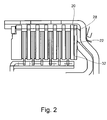
- Fig. 2 is the multi-plate clutch of FIG. 1 shown in the actuated state.
- the actuation state corresponds to a torque transmission capacity which is approximately in the range of 20 Nm to 50 Nm and is run through during startup.
- the elastic element 22 is pressed by the actuator 16 against its spring force to the adjacent blade 20, so that the second, radially inner edge region 32, comes to rest on the blade 20.
- the elastic element 22 now lies against the adjacent lamella 20 both in a region radially outward, the first edge region 28, and radially inward, the second edge region 32.
- the average radius range of the elastic element 22 on which the actuator 16 acts does not abut against the adjacent lamella 20 and thus can still spring relative to the contact point of the actuator.
- Fig. 3 is the same multi-plate clutch as in FIG. 1 and 2 shown, but at Nennanpresskraft of the actuator 16.
- the second edge region 32 which rests against the adjacent blade 20 is greatly enlarged radially outward, whereas the first edge region 28 remains substantially constant.
- the elastic element 22 still does not abut the adjacent lamella 20.
- FIG. 4 is a wet-running dual clutch assembly with two multi-plate clutches 2, 102 shown.
- the radially inner multi-plate clutch 2 corresponds to the multi-plate clutch of FIGS. 1 to 3
- the actuators 26, 126 are designed as hydraulically actuated pistons.
- the axial stop 118 of the radially outer multi-disc clutch is formed as a circumferential recess in the driver 60, which is welded to the outer disk carrier 104.
- Torque is transmitted from the drive unit to the two multi-disc clutches 102, 2 via the driver 60.
- the elastic element 122 is arranged on the piston 126 opposite side of the disk set between the Axialabstützung 118 and the last fin of the disk set.
- the axial support 118 in this case acts on the middle radius region of the elastic element, which initially does not come into contact with the last lamella when actuated.
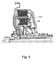
- the dual clutch arrangement of FIG. 5 corresponds to the elastic member 222 of the dual clutch assembly of FIG. 4 ,
- the elastic element 222 is here likewise designed as an outer lamella, however, the adjacent first edge region 28 is formed radially inward and the second region axially offset region, which is axially spaced from the adjacent lamella, extends radially outward into the toothed region.
- the operation of the elastic member 222 is identical to that of the elastic member 22, only in reverse. When operating the multi-plate clutch 2, the radially outer edge region is brought to bear against the adjacent blade.
- FIG. 6 shows an alternative multi-plate clutch in the non-actuated state, which in addition to the elastic member 22, a second elastic member 322nd having.
- the elastic element 322 rests against the last outer lamella 320 with the first radially inner edge region 328.
- the elastic element 322 is thicker in the first edge region 328 of the material thickness.
- the elastic element 22 rests radially on the outside of the adjacent lamella and the elastic element 322 radially on the inside of the adjacent lamella 320.
- FIG. 7 shows the multi-plate clutch of FIG. 6 in the actuated state.
- the elastic elements 22, 322 are pivoted counter to their spring force to the left.
- both the first edge region and the second edge region of both elastic elements 22, 322 rest against the adjacent lamellae. It is understood that the multi-plate clutch of FIGS. 6 and 7 even with the omission of the elastic element 22 and only with the elastic element 322 can be configured.
- FIG. 8 is shown in comparison the qualitative course of the force application radius over the spring travel of a resilient element according to the prior art and according to the invention.
- the course of the force application radius of the elastic element according to the invention does not have a slow transition over the spring travel of the elastic element to a middle radius region of the elastic element, but a stepped transition from a radially outer region to a central region. This is due to the fact that with application of the radially inner region of the elastic element on the adjacent lamella, the force application radius runs directly onto a central region, although the end of the spring travel has not yet been reached.
- FIG. 8 is shown on the abscissa of the spring travel of the elastic element and on the ordinate of the force application radius.
- r A corresponds to the outer radius of the elastic element and rl the inner radius.
- SE the end of the spring travel of the elastic element is marked.
Description
Die Erfindung betrifft eine Lamellenkupplung im Antriebsstrang eines Kraftfahrzeuges. Solche Lamellenkupplungen sind allgemein bekannt. Üblicher weise bestehen die Lamellenkupplungen aus einem Außenlamellenträger mit einem Verzahnungsprofil an weichem Außenlamellen drehfest und axial verschiebbar angeordnet sind und einem Innenlamellenträger mit einem Verzahnungsprofil an weichem Innlamellen drehfest und axial verschiebbar angeordnet sind. Die Außen- und Innenlamellen sind wechselseitig angeordnet und bilden ein Lamellenpaket. Zur Drehmomentübertragung wird das Lamellenpaket von einem Aktuator zusammengedrückt, wodurch die Lamellen in Reibeingriff gebracht werden. Die Lamellen können als Stahllamellen und als belagtragende Lamellen ausgebildet sein, wobei beim Betätigen immer eine Seite einer Lamelle welche einen Belag aufweist mit einer benachbarten Lamelle, welche keinen Belag aufweist, in Reibeingriff gebracht wird.The invention relates to a multi-plate clutch in the drive train of a motor vehicle. Such multi-plate clutches are well known. Conventionally, the multi-plate clutches consist of an outer disk carrier with a tooth profile on soft outer disk rotation and axially displaceable and an inner disk carrier with a tooth profile of soft Innlamellen rotatably and axially slidably disposed. The outer and inner disks are mutually arranged and form a disk pack. For torque transmission, the disk pack is compressed by an actuator, whereby the slats are brought into frictional engagement. The lamellae can be designed as steel lamellae and as lining-carrying lamellae, wherein upon actuation always one side of a lamella which has a lining is brought into frictional engagement with an adjacent lamella, which has no lining.
Der Aktuator kann beispielsweise als hydraulisch betätigter Kolben ausgeführt sein. Wird eine solche Lamellenkupplung als Anfahrkupplung verwendet, ist besonders bei beginnender Drehmomentübertragung im niedrigen Drehmomentbereich das Drehmomentübertragungsverhalten der Kupplung besonders empfindlich gegenüber Drehmomentschwankungen, welche sich hier überproportional stark auswirken, wenn die Drehzahl der schlupfenden Kupplung mit ihren Anregungen die Eigenfrequenz des Antriebsstranges trifft. So können Schwankungen in der Dicke einzelner Lamellen Drehmomentschwankungen im übertragenen Drehmoment der Kupplung bewirken, welche sich auf den gesamten nachfolgenden Antriebsstrang übertragen und zu einem Ruckeln des Fahrzeugs oder einem Zittern beim Anfahren führen können.The actuator may for example be designed as a hydraulically operated piston. If such a multi-plate clutch is used as a starting clutch, especially at the beginning of torque transmission in the low torque range, the torque transmission behavior of the clutch is particularly sensitive to torque fluctuations, which affect disproportionately strong here, if the speed of the slipping clutch with its suggestions hits the natural frequency of the drive train. Thus, variations in the thickness of individual disks can cause torque fluctuations in the transmitted torque of the clutch, which can be transmitted to the entire subsequent drive train and can lead to a jerking of the vehicle or a jitter during startup.
Aus der
Aus der
Drehmomentschwankungen des übertragenen Drehmoments treten besonders immer dann auf, wenn die beiden Kupplungsseiten mit unterschiedlicher Drehzahl rotieren, wie zum Beispiel beim Anfahren, und der Anpressdruck infolge von Dickenschwankungen einzelner Lamellen schwankt. Das Drehmoment wird immer dann erhöht wenn eine Erhebung in einer Lamelle eine Erhebung in einer anderen Lamelle, welche mit unterschiedlicher Drehzahl rotiert, passiert, oder wenn der Kolben oder die gegenüberliegende Abstützung des Lamellenpaketes eine Schiefstellung aufweist und die Erhebung in einer Lamelle die durch den Kolben beziehungsweise die gegenüberliegende Abstützstelle definierte Engstelle passiert. Die bekannten federnden Elemente im Lamellenpaket dienen dazu, eine Elastizität in das Lamellenpaket zu bringen, welche Drehmomentungleichförmigkeiten aufgrund von Dickenschwankungen einzelner Lamellen abfedern können.Torque fluctuations of the transmitted torque occur especially when the two sides of the clutch rotate at different speeds, such as when starting, and the contact pressure fluctuates due to thickness variations of individual slats. The torque is always increased when a survey in a lamella a survey in another lamella, which rotates at different speeds, happens, or when the piston or the opposite support of the plate package has a misalignment and the collection in a lamella through the piston or the opposite support point defined bottleneck happened. The known resilient elements in the disk set serve to provide elasticity to bring the disk set, which torque irregularities due to thickness variations of individual slats can cushion.
Nachteilig bei den bekannten Lösungen ist jedoch, dass die federnden Elemente nur in einem Randbereich der benachbarten Lamelle anliegen und somit eine ungleiche Pressungverteilung ins Lamellenpaket eingebracht wird. Diese Ungleichheit ist zwar bei relativ geringen übertragenen Drehmomenten wie beim Anrollen, noch unkritisch, jedoch nicht vernachlässigbar. Um die Pressungsverteilung bei höherem Anpressdruck zu optimieren, sind die federnden Elemente so schwach ausgelegt, das bei einem höheren Anpressdruck das elastische Element plan an der benachbarten Lamelle angedrückt wird. Beim Betätigen des Lamellenpaketes mittels des Aktuators verschiebt sich der Kraftangriffsradius der auf die dem elastischen Element benachbarte Lamelle wirkt, allmählich vom Randbereich hin zur radialen Mitte des Lamellenpaketes.A disadvantage of the known solutions, however, is that the resilient elements rest only in an edge region of the adjacent lamella and thus an unequal distribution of pressure is introduced into the lamella packet. Although this inequality is still not critical at relatively low transmitted torques as when rolling, but not negligible. In order to optimize the pressure distribution at higher contact pressure, the resilient elements are designed so weak that at a higher contact pressure, the elastic element is pressed flat on the adjacent blade. Upon actuation of the disk pack by means of the actuator, the force application radius which acts on the disk adjacent to the elastic element shifts gradually from the edge region to the radial center of the disk pack.
Aufgabe der Erfindung ist es, eine Lamellenkupplung darzustellen, welche ausgehend vom aufgezeigten Stand der Technik eine verbesserte Krafteinleitung und damit eine verbesserte Pressungsverteilung aufweist.The object of the invention is to present a multi-plate clutch which, starting from the indicated prior art, has an improved introduction of force and thus an improved pressure distribution.
Diese Aufgabe wird gelöst durch die Merkmale des Anspruchs 1.This object is achieved by the features of claim 1.
Erfindungsgemäß ist das elastische Element so ausgebildet ist, dass beim Betätigen des Lamellenpaketes, das elastische Element an dem, dem ersten Randbereich gegenüberliegenden, zweiten Randbereich des Lamellenpaketes, der benachbarten Lamelle zum Anliegen kommt, und in dem mittlerem Radiusbereich das elastische Element nicht an der benachbarten Lamelle zum Anliegen kommt. Liegt das elastische Element mit seinem ersten Randbereich radial außen an der benachbarten Lamelle an, wird beim Betätigen der zweite Randbereich, der radial innerer Bereich, zur Anlage gebracht ohne das der radial mittlere Bereich zur Anlage kommt. Liegt das elastische Element mit seinem ersten Randbereich radial innen an der benachbarten Lamelle an, wird beim Betätigen der zweite Randbereich, der radial äußere Bereich, zur Anlage gebracht ohne das der radial mittlere Bereich zur Anlage kommt.According to the invention, the elastic element is designed such that upon actuation of the disk pack, the elastic element comes into contact with the second edge region of the disk pack opposite the first edge region, the adjacent disk, and in the middle radius region the elastic element Element does not come to rest on the adjacent lamella. If the elastic element lies with its first edge region radially on the outside of the adjacent lamella, during actuation the second edge region, the radially inner region, is brought into abutment without the radially middle region coming into abutment. If the elastic element lies with its first edge region radially inward on the adjacent lamella, upon actuation the second edge region, the radially outer region, is brought into abutment without the radially middle region coming into abutment.
Vorteilhaft hierbei ist, dass sich das elastische Element nicht ausgehend vom ersten anliegenden Randbereich beim Betätigen der Lamellenkupplung kontinuierlich über die Mitte bis zum gegenüberliegenden Randbereich hin an die benachbarte Lamelle anlegt, sondern dass beim Betätigen der Lamellenkupplung zuerst der zweite Randbereich an der benachbarten Lamelle zum Anliegen kommt, wobei in dem mittlerem Radiusbereich das elastische Element nicht an der benachbarten Lamelle zum Anliegen kommt. Während es beim Stand der Technik erst bei völligem Anliegen des elastischen Elementes an der benachbarten Lamelle und damit erst am Ende des Federweges des elastischen Elementes zu einer Krafteinleitung an dem zweiten Randbereich kommt, wird bei der Erfindung bereits viel früher und damit noch im federnden Bereich des elastischen Elementes eine Krafteinleitung am zweiten Randbereich realisiert. Hierdurch verschiebt sich der mittlere Kraftangriffsradius auf die dem elastischen Element benachbarte Lamelle nicht kontinuierlich zur radialen Mitte des Lamellenpaketes hin und erreicht erst am Ende des Federweges des elastischen Elementes im Wesentlichen den Kraftangriffsradius des Aktuators. Nach der Erfindung wird der mittlere Kraftangriffsradius bereits beim Anliegen des elastischen Elementes am zweiten Randbereich der benachbarten Lamelle erreicht und bleibt dann im Wesentlichen über den restlichen Federweg konstant.The advantage here is that the elastic element does not start, starting from the first adjacent edge region when operating the multi-plate clutch continuously over the middle to the opposite edge region to the adjacent blade, but that upon actuation of the multi-plate clutch first, the second edge region of the adjacent blade for concern comes, in the middle radius range, the elastic element does not come to rest on the adjacent blade. While it comes in the prior art only with complete concern of the elastic element on the adjacent blade and thus only at the end of the spring travel of the elastic element to a force on the second edge region, much earlier in the invention and thus still in the resilient region of the invention elastic element realized a force on the second edge region. As a result, the average force application radius does not shift continuously towards the radial element of the disk pack toward the disk adjacent to the elastic element and only substantially reaches the force application radius of the actuator at the end of the spring travel of the elastic element. According to the invention, the average force application radius is already at the concern of the reaches elastic element at the second edge region of the adjacent blade and then remains substantially constant over the remaining travel.
Eine besonders vorteilhafte Ausgestaltung des elastischen Elementes sieht hierbei vor, dass der Verlauf des Kraftangriffsradius im federnden Bereich des elastischen Elementes einen Sprung aufweist, wohingegen der Verlauf der Kraft im federnden Bereich im Wesentlichen linear verläuft. Vorteilhaft hierbei ist, dass durch den linearen Kraftverlauf eine vorteilhafte Regelung der Lamellenkupplung möglich wird. Weiterhin erfolgt ein weicher Übergang des Kraftverlaufs vom federnden Bereich in den nichtfedernden Bereich, wenn das elastische Element quasi plan anliegt.A particularly advantageous embodiment of the elastic element provides in this case that the course of the force application radius in the resilient region of the elastic element has a jump, whereas the course of the force in the resilient region is substantially linear. The advantage here is that an advantageous control of the multi-plate clutch is possible by the linear force curve. Furthermore, a smooth transition of the force curve from the resilient region into the non-resilient region occurs when the elastic element rests virtually flat.
Eine vorteilhafte Weiterbildung der Erfindung sieht vor, dass das elastische Element als Außenlamelle ausgebildet ist und mit einem Verzahnungsprofil im Außenlamellenträger getragen wird. Hierdurch wird eine radiale Führung des elastischen Elementes gewährleistet und außerdem kann sich das elastische Element nicht mehr relativ zur benachbarten Lamelle verdrehen. Voraussetzung hierbei ist, dass sowohl das elastische Element als auch die benachbarte Lamelle als Außenlamellen oder als Innenlamellen ausgebildet sind.An advantageous development of the invention provides that the elastic element is designed as an outer plate and is supported with a tooth profile in the outer plate carrier. As a result, a radial guidance of the elastic element is ensured and, moreover, the elastic element can no longer rotate relative to the adjacent lamella. The prerequisite here is that both the elastic element and the adjacent lamella are formed as outer plates or as inner plates.
Das elastische Element ist vorzugsweise so ausgebildet, dass das elastische Element einen ersten Bereich und einen davon axial abgestuften zweiten Bereich aufweist, wobei der erste Bereich bei unbetätigter Lamellenkupplung an der benachbarten Lamelle anliegt und das Verhältnis von erstem Bereich zu zweitem Bereich zwischen 1/7 und 3/7 liegt. Erfindungsgemäß entspricht der erste Bereich dem ersten anliegenden Randbereich, wohingegen der zweite Randbereich nur einen Teil des zweiten Bereichs bildet. In der bevorzugten Ausgestaltung des elastischen Elementes als Außenlamelle ist der erste und der zweite Bereich so definiert, das der erste und der zweite Bereich zusammengenommen die gesamte Radialerstreckung des elastischen Elementes bilden und somit der Verzahnungsbereich entweder dem ersten oder dem zweiten Bereich zugehörig ist. Da der Verzahnungsbereich im Falle einer Außenlamelle der radial äußere Randbereich ist, wird über diesen bei Anliegen am Verzahnungsbereich der benachbarten Außenlamelle Drehmoment übertragen. Das erfindungsgemäße Verhältnis von erstem zu zweitem Bereich gewährleistet, dass beim Betätigen der Lamellenkupplung das übertragenen Drehmoment beim Anfahren, welches weit geringer ist als das maximal übertragbare Drehmoment, die an der benachbarten Lamelle anliegenden Flächen des ersten und des zweiten Randbereichs des elastischen Elementes im Wesentlichen gleich groß sind.The elastic element is preferably formed such that the elastic element has a first region and a second region axially stepped therefrom, wherein the first region rests against the adjacent lamella when the lamina coupling is not actuated and the ratio between the first region and the second region is between 1/7 and 3/7 lies. According to the invention, the first region corresponds to the first one adjacent edge region, whereas the second edge region forms only a part of the second region. In the preferred embodiment of the elastic element as an outer fin, the first and second regions are defined so that the first and second regions together form the entire radial extension of the elastic element and thus the toothed region is associated with either the first or the second region. Since the toothing region in the case of an outer disk is the radially outer edge region, torque is transmitted via the latter when it contacts the toothed region of the adjacent outer disk. The ratio of the first to the second range according to the invention ensures that upon actuation of the multi-plate clutch, the transmitted torque during starting, which is far lower than the maximum transmittable torque, substantially equal to the surfaces of the first and the second edge regions of the elastic element adjacent to the adjacent plate are big.
Eine weitere bevorzugte Weiterbildung der Erfindung sieht vor, dass die axiale Stufe zwischen 10% und 90%, vorzugsweise zwischen 10% und 50%, der Materialstärke des ersten Bereichs entspricht. Vorteilhaft hierbei ist, dass die Stufe in der vorzugsweise aus Stahlblech ausgeführten Außenlamelle eingeprägt werden kann, und dass der erste Bereich nicht mehr als die axiale Materialstärke in diesem Bereich zum zweiten Bereich axial versetzt ist. Weiterhin sind herstellungsbedingte Toleranzen einer Stufe besser beherrschbar als bei einer Tellerfeder. Vorzugsweise liegt der zweite Bereich des elastischen Elementes in einer, um die axiale Stufe versetzten, parallelen Ebene zum ersten Bereich. Es kann jedoch auch vorteilhaft sein, das der zweite Bereich zum ersten Bereich zusätzlich zur Stufe noch einen Winkel aufweist, welcher vorzugsweise zwischen 1° und 10°, höchstvorzugsweise zwischen 1° und 5° beträgt, so daß der zweite Bereich zur benachbarten Lamelle weggeneigt ist und somit der zweite Randbereich weiter als nur die Stufenhöhe der axialen Stufe von der benachbarten Lamelle beabstandet ist. Vorteilhaft bei der Kombination von Stufung und Tellerung des elastischen Elementes ist, dass bei der Herstellung die Elastizität des Elementes sowohl durch die Stufe als auch durch die Tellerung eingestellt und optimiert werden kann.A further preferred development of the invention provides that the axial step corresponds to between 10% and 90%, preferably between 10% and 50%, of the material thickness of the first region. The advantage here is that the step can be stamped in the outer plate preferably made of sheet steel, and that the first region is not offset axially more than the axial material thickness in this area to the second region. Furthermore, manufacturing tolerances of a stage are better controlled than a plate spring. Preferably, the second region of the elastic element lies in a plane parallel to the first region offset by the axial step. However, it can also be advantageous that the second area to the first area still has an angle in addition to the step, which is preferably between 1 ° and 10 °, most preferably between 1 ° and 5 ° so that the second region is inclined away from the adjacent blade and thus the second edge region is spaced further than the step height of the axial step from the adjacent blade. An advantage of the combination of gradation and Tellerung of the elastic element is that during manufacture, the elasticity of the element can be adjusted and optimized both by the stage and by the Tellerung.
Vorzugsweise ist die axiale Materialstärke des ersten und des zweiten Bereichs gleich stark, so daß das elastische Element aus einer planen Scheibe gefertigt werden kann. Es kann jedoch aus erfindungsgemäß vorgesehen sein, das die Materialstärke des ersten Bereichs um die axiale Stufe dicker ausgebildet ist als der zurückgesetzte zweite Bereich.Preferably, the axial thickness of the first and the second region is equally strong, so that the elastic element can be made of a flat disc. However, it may be provided according to the invention that the material thickness of the first region around the axial step is made thicker than the recessed second region.
Eine bevorzugte Anordnung des elastischen Elementes im Lamellenpaket sieht vor, dass das elastische Element zwischen dem Aktuator und der ersten benachbarten Außenlamelle angeordnet ist.A preferred arrangement of the elastic element in the disk set provides that the elastic element is arranged between the actuator and the first adjacent outer disk.
Vorteilhaft hierbei ist, dass die axiale Schwingfähigkeit des Lamellenpaketes reduziert wird. Axiale Schwingungen, die vom Aktuator auf das Lamellenpaket übertragen würden, werden vom zwischen dem Aktuator und dem Lamellenpaket angeordneten elastischen Element abgemildert. Hierdurch werden sowohl die Drehmomentschwankungen aufgrund von Dickenschwankungen der Lamellen weggefiltert, als auch Drehmomentschwankungen aufgrund von axialen Schwingungen oder Anpresskraftschwankungen des Aktuators. Die Masse des Lamellenpaketes ist am gegenüberliegenden festen Axialanschlag abgestützt und somit aus dem schwingfähigen System ausgekoppelt.The advantage here is that the axial vibration capacity of the disk set is reduced. Axial vibrations that would be transmitted from the actuator to the disk pack are mitigated by the arranged between the actuator and the disk pack elastic element. As a result, both the torque fluctuations due to thickness variations of the fins are filtered away, as well as torque fluctuations due to axial vibrations or Anpresskraftschwankungen the actuator. The mass of the Disc pack is supported on the opposite fixed axial stop and thus decoupled from the oscillatory system.
Liegt hingegen das Lamellenpaket direkt am Aktuator an und ist das elastische Element am gegenüberliegenden Ende des Lamellenpaketes angeordnet, werden zwar die Drehmomentschwankungen aufgrund von Dickenschwankungen der Lamellen weggefiltert, jedoch stellt die Masse des Lamellenpaketes ein schwingfähiges System dar, welches von Axialschwingungen des Aktuators angeregt werden kann.If, on the other hand, the disk set lies directly on the actuator and the elastic element is arranged at the opposite end of the disk set, the torque fluctuations due to thickness variations of the disks are filtered away, but the mass of the disk set represents an oscillatory system which can be excited by axial vibrations of the actuator ,
Eine besonders bevorzugte Ausgestaltung des Aktuators sieht vor, dass der Aktuator mit einer balligen Anlagefläche auf den mittleren Radiusbereich des elastischen Elementes wirkt. Vorteilhaft hierbei ist, dass der Aktuator auf den Bereich des elastischen Elementes wirkt, welcher bei Anliegen des ersten und des zweiten Randbereiches noch nicht an der benachbarten Lamelle anliegt, und somit noch federnd wirkt.A particularly preferred embodiment of the actuator provides that the actuator acts with a convex contact surface on the central radius region of the elastic element. The advantage here is that the actuator acts on the region of the elastic element, which does not abut against the adjacent lamella when concerns the first and second edge region, and thus still acts resiliently.
Da bei der Betätigung der Lamellenkupplung das elastische Element erfindungsgemäß eine Kippbewegung um den Anlagepunkt des Aktuators macht, dient die ballige Anlagefläche dazu, dass der Anlagepunkt des elastischen Elementes am Aktuator abrollen kann, ohne über eine Kante zu kippen. Der Aktuator greift vorzugsweise mit einer Stirnfläche an der elastischen Lamelle an, welche in ihrer radialen Erstreckung in etwa der Materialstärke der Lamellen entspricht. Die Stirnfläche des Aktuators kann hierbei abgerundet oder dachförmig ausgebildet sein. Eine alternative oder zusätzliche Ausbildung der Erfindung sieht vor, dass das elastische Element auf der dem Aktuator axial entgegengesetzten Seite des Lamellenpaketes zwischen der letzten Außenlamelle des Lamellenpaketes und einem Axialschlag, welcher das elastische Element axial abstützt, angeordnet ist. Vorzugsweise wirkt der Axialanschlag auf den mittleren Radiusbereich des elastischen Elementes. Hierbei liegt, wie auch bei der aktuatorseitigen Anordnung des elastischen Elementes, der Krafteinleitungsradius beziehungsweise der Kraftabstützungsradius in dem mittleren Radiusbereich, welcher bei Anliegen des ersten und des zweiten Randbereiches noch beabstandet von der benachbarten Lamelle, und somit noch federnd wirkt.Since, in the actuation of the multi-plate clutch, the elastic element according to the invention makes a tilting movement about the contact point of the actuator, the spherical contact surface serves that the contact point of the elastic element can roll on the actuator without tilting over an edge. The actuator preferably engages with an end face on the elastic blade, which corresponds in its radial extent in approximately the material thickness of the slats. The end face of the actuator can here be rounded or roof-shaped. An alternative or additional embodiment of the invention provides that the elastic element on the actuator axially opposite side of the disk set between the last outer disk of the disk set and an axial shock, which axially supports the elastic element, is arranged. The axial stop preferably acts on the middle radius region of the elastic element. In this case, as with the actuator-side arrangement of the elastic element, the force introduction radius or the Kraftabstützungsradius in the middle radius region, which still concerns spaced from the adjacent blade, and thus still resilient when concerns the first and second edge region.
Die Erfindung wird nachfolgend anhand von Figuren dargestellt.The invention is illustrated below with reference to figures.
Es zeigt:
-
Fig. 1 eine erste erfindungsgemäße Lamellenkupplung im nichtbetätigtem Zustand -
Fig. 2 die erste erfindungsgemäße Lamellenkupplung im betätigtem Zustand -
Fig 3 . die erste erfindungsgemäße Lamellenkupplung bei Nennanpresskraft -
Fig 4 . eine Doppelkupplungsanordnung mit zwei erfindungsgemäßen Lamellenkupplungen -
Fig. 5 eine alternative Doppelkupplungsanordnung -
Fig. 6 eine zweite erfindungsgemäße Lamellenkupplung im nichtbetätigtem Zustand -
Fig. 7 eine zweite erfindungsgemäße Lamellenkupplung im betätigtem Zustand -
Fig. 8 oben einen Verlauf des Kraftangriffsradius einer Lamellenkupplung nach dem Stand der Technik
-
Fig. 1 a first multi-plate clutch according to the invention in the non-actuated state -
Fig. 2 the first multi-plate clutch according to the invention in the actuated state -
Fig. 3 , the first multi-plate clutch according to the invention at Nennanpresskraft -
Fig. 4 , a dual clutch assembly with two multi-plate clutches according to the invention -
Fig. 5 an alternative dual clutch arrangement -
Fig. 6 a second multi-plate clutch according to the invention in the non-actuated state -
Fig. 7 a second multi-plate clutch according to the invention in the actuated state -
Fig. 8 above a profile of the force application radius of a multi-plate clutch according to the prior art
In
Das elastische Element 22 liegt nur im radial äußeren Randbereich an der benachbarten Außenlamelle 20 an. Der Aktuator liegt mit einer balligen Stirnfläche 24 im mittleren Radiusbereich des elastischen Elements 22 an. Das elastische Element 22 weist eine axiale Stufe 26, welche den anliegenden ersten Randbereich 28 begrenzt. Die Stufe trennt den ersten Bereich, welcher dem ersten Randbereich 28 entspricht, vom zweiten Bereich 30 ab, welcher gegenüber dem ersten Bereich 28 ausgestellt ist.The
In
In
In
Über den Mitnehmer 60 wird Drehmoment von der Antriebseinheit zu den beiden Lamellenkupplungen 102, 2 übertragen.Torque is transmitted from the drive unit to the two
Das elastische Element 122 ist an der dem Kolben 126 entgegengesetzten Seite des Lamellenpakets zwischen der Axialabstützung 118 und der letzten Lamelle des Lamellenpakets angeordnet. Die Axialabstützung 118 wirkt hierbei auf den mittleren Radiusbereich des elastischen Elementes, welcher beim Betätigen zunächst nicht zur Anlage an der letzten Lamelle kommt.The
Die Doppelkupplungsanordnung der
In
In
Unter Kraftangriffsradius ist hierbei der Radiusbereich zu verstehen in welchem eine linienförmige Ersatzkraft auf die dem elastischen Element benachbarte Lamelle wirken würde. Das elastische Element überträgt die Betätigungskraft des Aktuators auf die benachbarte Lamelle und damit auf das gesamte Lamellenpaket. Liegt das elastische Element komplett an der benachbarten Lamelle an, liegt der Kraftangriffsradius im mittleren Radiusbereich des elastischen Elementes. Da der anliegende Bereich des elastischen Elementes aus dem Stand der Technik kontinuierlich von radial außen nach radial innen zunimmt, verläuft der Kraftangriffsradius entsprechend kontinuierlich von radial außen zu einem mittleren Radiusbereich. Der radial mittlere Bereich wird somit erst am Ende des Federweges des elastischen Elementes erreicht. In
Der Verlauf des Kraftangriffsradius des erfindungsgemäßen elastischen Elements weißt keinen langsamen Übergang über den Federweg des elastischen Elementes zu einem mittleren Radiusbereich des elastischen Elements auf, sondern einen gestuften Übergang von einem radial äußeren Bereich zu einem mittleren Bereich. Dies rührt daher, dass mit Anliegen des radial inneren Bereichs des elastischen Elementes an der benachbarten Lamelle der Kraftangriffsradius unmittelbar auf einen mittleren Bereich hinläuft, obwohl das Ende des Federweges noch nicht erreicht ist.The course of the force application radius of the elastic element according to the invention does not have a slow transition over the spring travel of the elastic element to a middle radius region of the elastic element, but a stepped transition from a radially outer region to a central region. This is due to the fact that with application of the radially inner region of the elastic element on the adjacent lamella, the force application radius runs directly onto a central region, although the end of the spring travel has not yet been reached.
In
Claims (8)
- Multiple disc clutch (2) having outer discs (8) which are supported by an outer disc carrier (4) which can be rotated about a rotational axis, and having inner discs (14) which are supported by an inner disc carrier (10) which can be rotated about the rotational axis, the outer discs and the inner discs forming an annular multiple disc assembly with an inner radius and an outer radius, and having an axially movable actuator for actuating the multiple disc assembly, the actuator acting, upon actuation, in a middle radius region (with regard to the rotational axis) of the multiple disc assembly, and the multiple disc assembly comprising an elastic element (22) which, in the non-actuated state of the multiple disc clutch, bears against its adjacent disc only in a first, outer or inner, edge region of the multiple disc assembly, characterized in that the elastic element is configured in such a way that, upon actuation of the multiple disc assembly, the elastic element (22) comes to bear against the adjacent disc (20) first of all at the second (32), inner or outer, edge region of the multiple disc assembly, which second edge region (32) lies opposite the first edge region (28), and the elastic element does not come to bear against the adjacent disc (20) in the middle radius region.
- Multiple disc clutch according to Claim 1, characterized in that the elastic element is configured as an outer disc and is supported by way of a toothing profile (6) in the outer disc carrier (4).
- Multiple disc clutch according to Claim 1, characterized in that the elastic element (22) has a first region (32) and a second region (28) which is stepped axially from the said first region (32), the second region (28) bearing against the adjacent disc when the multiple disc clutch is non-actuated, and the ratio of first region to second region lying between 1/7 and 3/7.
- Multiple disc clutch according to Claim 1, characterized in that the axial step (26) corresponds to between 10% and 90% of the material thickness of the first region.
- Multiple disc clutch according to Claim 2, characterized in that the elastic element (22) is arranged between the actuator (16) and the first adjacent outer disc (20).
- Multiple disc clutch according to Claim 5, characterized in that the actuator acts with a spherical stop face (24) on the middle radius region of the elastic element.
- Multiple disc clutch according to Claim 2, characterized in that the elastic element (122) is arranged on that side of the multiple disc assembly which is axially opposite the actuator, between the last outer disc of the multiple disc assembly and an axial stop which supports the elastic element axially.
- Multiple disc clutch according to Claim 7, characterized in that the axial stop acts on the middle radius region of the elastic element.
Priority Applications (3)
| Application Number | Priority Date | Filing Date | Title |
|---|---|---|---|
| EP09170396A EP2299140B1 (en) | 2009-09-16 | 2009-09-16 | Lamella coupling with elastic element |
| US12/882,768 US8602192B2 (en) | 2009-09-16 | 2010-09-15 | Multiple-disk clutch with resilient element |
| CN201010286024.XA CN102022448B (en) | 2009-09-16 | 2010-09-16 | Lamella coupling with elastic element |
Applications Claiming Priority (1)
| Application Number | Priority Date | Filing Date | Title |
|---|---|---|---|
| EP09170396A EP2299140B1 (en) | 2009-09-16 | 2009-09-16 | Lamella coupling with elastic element |
Publications (2)
| Publication Number | Publication Date |
|---|---|
| EP2299140A1 EP2299140A1 (en) | 2011-03-23 |
| EP2299140B1 true EP2299140B1 (en) | 2013-03-20 |
Family
ID=41682319
Family Applications (1)
| Application Number | Title | Priority Date | Filing Date |
|---|---|---|---|
| EP09170396A Active EP2299140B1 (en) | 2009-09-16 | 2009-09-16 | Lamella coupling with elastic element |
Country Status (3)
| Country | Link |
|---|---|
| US (1) | US8602192B2 (en) |
| EP (1) | EP2299140B1 (en) |
| CN (1) | CN102022448B (en) |
Families Citing this family (12)
| Publication number | Priority date | Publication date | Assignee | Title |
|---|---|---|---|---|
| DE69220871T2 (en) | 1991-10-03 | 1997-11-20 | Bayer Ag | Device and method for the separation and analysis of whole blood |
| CN101595320B (en) * | 2007-01-29 | 2011-11-30 | 舍弗勒技术两合公司 | Drive train having a wet starting clutch for hybrid applications |
| DE202011002608U1 (en) * | 2011-02-11 | 2012-02-29 | Camera Dynamics Gmbh | tripod head |
| WO2014012544A1 (en) * | 2012-07-20 | 2014-01-23 | Schaeffler Technologies AG & Co. KG | Coupling device and an outer plate carrier |
| US9541139B2 (en) | 2012-12-17 | 2017-01-10 | Schaeffler Technologies AG & Co. KG | Clutch |
| FR3025848B1 (en) | 2014-09-15 | 2018-01-26 | Valeo Embrayages | DEVICE FOR DOUBLE WET CLUTCH |
| US10253827B1 (en) * | 2014-12-10 | 2019-04-09 | Sonnax Transmission Company | Clutch apply piston assembly for automotive transmissions |
| DE102016213218B4 (en) * | 2016-07-20 | 2020-10-22 | Schaeffler Technologies AG & Co. KG | Coupling device |
| DE112017004826A5 (en) * | 2016-09-27 | 2019-06-13 | Schaeffler Technologies AG & Co. KG | Multi-disc / multi-plate clutch for torque modulation |
| DE102016221748A1 (en) * | 2016-11-07 | 2018-05-09 | Schaeffler Technologies AG & Co. KG | coupling device |
| CN112524171B (en) * | 2020-11-30 | 2022-03-01 | 无锡明恒混合动力技术有限公司 | Radial double-clutch structure for hybrid power transmission |
| CN112524172B (en) * | 2020-11-30 | 2022-03-22 | 无锡明恒混合动力技术有限公司 | Axial double-clutch structure for hybrid power transmission |
Family Cites Families (19)
| Publication number | Priority date | Publication date | Assignee | Title |
|---|---|---|---|---|
| US4371066A (en) | 1978-12-29 | 1983-02-01 | Nissan Motor Company, Limited | Wet multiple disc clutch device for a vehicle transmission |
| JPS59155627A (en) * | 1983-02-22 | 1984-09-04 | Kamizaki Kokyu Koki Seisakusho Kk | Multiple-disc type hydraulic clutch for hydraulic-clutch type speed change gear |
| JPS6086627U (en) * | 1983-11-18 | 1985-06-14 | 株式会社大金製作所 | hydraulic clutch |
| US4949829A (en) * | 1987-08-03 | 1990-08-21 | Kabushiki Kaisha Daikin Seisakusho | Clutch cover assembly with annular coned disc spring |
| JP3248749B2 (en) * | 1992-03-19 | 2002-01-21 | ジヤトコ・トランステクノロジー株式会社 | Spring retainer for clutch piston |
| DE19530443A1 (en) | 1995-08-18 | 1996-10-10 | Daimler Benz Ag | Axially engageable and disengageable position clutch |
| US5967283A (en) * | 1996-12-04 | 1999-10-19 | Kemper; Yves J. | Clutch spring assembly |
| JP4388233B2 (en) * | 2001-01-16 | 2009-12-24 | 富士重工業株式会社 | Friction engagement device for automatic transmission |
| JP3961313B2 (en) * | 2002-02-27 | 2007-08-22 | 本田技研工業株式会社 | Hydraulically operated multi-plate clutch device |
| DE10255537B4 (en) | 2002-11-28 | 2007-09-13 | Audi Ag | Hydraulically actuated multi-plate clutch |
| EP1577575B1 (en) | 2004-03-17 | 2012-04-18 | BorgWarner, Inc. | Multiple disc clutch |
| JP2006132548A (en) * | 2004-10-05 | 2006-05-25 | Nok Corp | Sealing device |
| JP2006200659A (en) * | 2005-01-21 | 2006-08-03 | Nsk Warner Kk | Multiple-disk type frictional engagement device and bush for multiple-disk type frictional engagement device |
| JP4619155B2 (en) * | 2005-03-08 | 2011-01-26 | Nskワーナー株式会社 | Multi-plate clutch |
| US20070261932A1 (en) * | 2006-05-12 | 2007-11-15 | Raytech Composites, Inc. | Friction clutch with multiple belleville springs |
| KR20090024020A (en) | 2007-09-03 | 2009-03-06 | 현대자동차주식회사 | Clutch system |
| JP2009115234A (en) * | 2007-11-07 | 2009-05-28 | Toyota Motor Corp | Friction engaging device |
| DE102008008918B4 (en) * | 2008-02-13 | 2018-02-01 | Hoerbiger Antriebstechnik Gmbh | multi-plate clutch |
| CN201180747Y (en) * | 2008-02-28 | 2009-01-14 | 刘珍利 | Wet-type multi-chip friction clutch |
-
2009
- 2009-09-16 EP EP09170396A patent/EP2299140B1/en active Active
-
2010
- 2010-09-15 US US12/882,768 patent/US8602192B2/en active Active
- 2010-09-16 CN CN201010286024.XA patent/CN102022448B/en active Active
Also Published As
| Publication number | Publication date |
|---|---|
| EP2299140A1 (en) | 2011-03-23 |
| CN102022448B (en) | 2014-12-31 |
| CN102022448A (en) | 2011-04-20 |
| US20110061984A1 (en) | 2011-03-17 |
| US8602192B2 (en) | 2013-12-10 |
Similar Documents
| Publication | Publication Date | Title |
|---|---|---|
| EP2299140B1 (en) | Lamella coupling with elastic element | |
| DE112008001561B4 (en) | Coupling arrangement, in particular wet-running dual clutch arrangement | |
| DE3720885C2 (en) | Damped flywheel clutch, especially for motor vehicles | |
| EP2494224B1 (en) | Clutch having a pre-clutch and a main clutch | |
| EP1298339B1 (en) | Multiple clutch assembly, in particular double clutch | |
| AT502707A2 (en) | BALL RAMP ASSEMBLY WITH VARIABLE SLOPING OF BALLILLAS | |
| DE102009057353A1 (en) | Multi-plate clutch with a spring device | |
| DE102008063662A1 (en) | Slat for a frictionally-acting device and frictionally-operating device with such a blade | |
| DE10016607B4 (en) | Dual clutch assembly | |
| DE1750841B1 (en) | FRICTION DISC COUPLING IN PARTICULAR FOR VEHICLES | |
| DE102007027120A1 (en) | Double clutch for use in transmission of motor vehicle, has supporting element designed as functionally effective protection element and formed to be intervened in annular groove formed in lamella carrier | |
| DE10149702A1 (en) | Multiple coupling device has each clutch disk device able to be coupled for rotating to another drive device | |
| WO2016124180A1 (en) | Coupling device and drive train having a coupling device | |
| EP2063146B1 (en) | Multi-disc clutch device | |
| EP3526886A1 (en) | Clutch device | |
| EP2452096A1 (en) | Torsional vibration damper arrangement, in particular in a clutch disc | |
| EP3504453A1 (en) | Double wrap spring, rotation device and system to be actuated | |
| DE102012224001A1 (en) | Clutch device i.e. single clutch, for powertrain of motor car, has coil comprising embossings, and lever element supported by portions and coil, where edges of embossings are brought in contact with portions or tolerance-afflicted system | |
| DE10013857A1 (en) | Double coupling | |
| EP2245324B1 (en) | Starting clutch, in particular for racing and sports vehicles | |
| DE10345321A1 (en) | Clutch and brake unit | |
| EP1876367B1 (en) | Multi-disc clutch system, in particular for commercial vehicles | |
| DE102015226264B4 (en) | Double clutch and use of a limiting flange | |
| EP1672235B2 (en) | Lamella for power transmission assembly and power transmission assembly with lamella | |
| EP3642508A1 (en) | Centrifugal clutch having centrifugal masses which are manufactured without cutting |
Legal Events
| Date | Code | Title | Description |
|---|---|---|---|
| PUAI | Public reference made under article 153(3) epc to a published international application that has entered the european phase |
Free format text: ORIGINAL CODE: 0009012 |
|
| AK | Designated contracting states |
Kind code of ref document: A1 Designated state(s): AT BE BG CH CY CZ DE DK EE ES FI FR GB GR HR HU IE IS IT LI LT LU LV MC MK MT NL NO PL PT RO SE SI SK SM TR |
|
| AX | Request for extension of the european patent |
Extension state: AL BA RS |
|
| 17P | Request for examination filed |
Effective date: 20110707 |
|
| 17Q | First examination report despatched |
Effective date: 20120315 |
|
| GRAP | Despatch of communication of intention to grant a patent |
Free format text: ORIGINAL CODE: EPIDOSNIGR1 |
|
| GRAS | Grant fee paid |
Free format text: ORIGINAL CODE: EPIDOSNIGR3 |
|
| GRAA | (expected) grant |
Free format text: ORIGINAL CODE: 0009210 |
|
| AK | Designated contracting states |
Kind code of ref document: B1 Designated state(s): AT BE BG CH CY CZ DE DK EE ES FI FR GB GR HR HU IE IS IT LI LT LU LV MC MK MT NL NO PL PT RO SE SI SK SM TR |
|
| REG | Reference to a national code |
Ref country code: GB Ref legal event code: FG4D Free format text: NOT ENGLISH |
|
| REG | Reference to a national code |
Ref country code: CH Ref legal event code: EP |
|
| REG | Reference to a national code |
Ref country code: IE Ref legal event code: FG4D Free format text: LANGUAGE OF EP DOCUMENT: GERMAN |
|
| REG | Reference to a national code |
Ref country code: AT Ref legal event code: REF Ref document number: 602261 Country of ref document: AT Kind code of ref document: T Effective date: 20130415 |
|
| REG | Reference to a national code |
Ref country code: DE Ref legal event code: R096 Ref document number: 502009006551 Country of ref document: DE Effective date: 20130516 |
|
| PG25 | Lapsed in a contracting state [announced via postgrant information from national office to epo] |
Ref country code: ES Free format text: LAPSE BECAUSE OF FAILURE TO SUBMIT A TRANSLATION OF THE DESCRIPTION OR TO PAY THE FEE WITHIN THE PRESCRIBED TIME-LIMIT Effective date: 20130701 Ref country code: BG Free format text: LAPSE BECAUSE OF FAILURE TO SUBMIT A TRANSLATION OF THE DESCRIPTION OR TO PAY THE FEE WITHIN THE PRESCRIBED TIME-LIMIT Effective date: 20130620 Ref country code: SE Free format text: LAPSE BECAUSE OF FAILURE TO SUBMIT A TRANSLATION OF THE DESCRIPTION OR TO PAY THE FEE WITHIN THE PRESCRIBED TIME-LIMIT Effective date: 20130320 Ref country code: NO Free format text: LAPSE BECAUSE OF FAILURE TO SUBMIT A TRANSLATION OF THE DESCRIPTION OR TO PAY THE FEE WITHIN THE PRESCRIBED TIME-LIMIT Effective date: 20130620 Ref country code: LT Free format text: LAPSE BECAUSE OF FAILURE TO SUBMIT A TRANSLATION OF THE DESCRIPTION OR TO PAY THE FEE WITHIN THE PRESCRIBED TIME-LIMIT Effective date: 20130320 |
|
| REG | Reference to a national code |
Ref country code: LT Ref legal event code: MG4D |
|
| PG25 | Lapsed in a contracting state [announced via postgrant information from national office to epo] |
Ref country code: FI Free format text: LAPSE BECAUSE OF FAILURE TO SUBMIT A TRANSLATION OF THE DESCRIPTION OR TO PAY THE FEE WITHIN THE PRESCRIBED TIME-LIMIT Effective date: 20130320 Ref country code: GR Free format text: LAPSE BECAUSE OF FAILURE TO SUBMIT A TRANSLATION OF THE DESCRIPTION OR TO PAY THE FEE WITHIN THE PRESCRIBED TIME-LIMIT Effective date: 20130621 Ref country code: LV Free format text: LAPSE BECAUSE OF FAILURE TO SUBMIT A TRANSLATION OF THE DESCRIPTION OR TO PAY THE FEE WITHIN THE PRESCRIBED TIME-LIMIT Effective date: 20130320 Ref country code: SI Free format text: LAPSE BECAUSE OF FAILURE TO SUBMIT A TRANSLATION OF THE DESCRIPTION OR TO PAY THE FEE WITHIN THE PRESCRIBED TIME-LIMIT Effective date: 20130320 |
|
| REG | Reference to a national code |
Ref country code: NL Ref legal event code: VDEP Effective date: 20130320 |
|
| PG25 | Lapsed in a contracting state [announced via postgrant information from national office to epo] |
Ref country code: HR Free format text: LAPSE BECAUSE OF FAILURE TO SUBMIT A TRANSLATION OF THE DESCRIPTION OR TO PAY THE FEE WITHIN THE PRESCRIBED TIME-LIMIT Effective date: 20130320 |
|
| PG25 | Lapsed in a contracting state [announced via postgrant information from national office to epo] |
Ref country code: SK Free format text: LAPSE BECAUSE OF FAILURE TO SUBMIT A TRANSLATION OF THE DESCRIPTION OR TO PAY THE FEE WITHIN THE PRESCRIBED TIME-LIMIT Effective date: 20130320 Ref country code: CZ Free format text: LAPSE BECAUSE OF FAILURE TO SUBMIT A TRANSLATION OF THE DESCRIPTION OR TO PAY THE FEE WITHIN THE PRESCRIBED TIME-LIMIT Effective date: 20130320 Ref country code: RO Free format text: LAPSE BECAUSE OF FAILURE TO SUBMIT A TRANSLATION OF THE DESCRIPTION OR TO PAY THE FEE WITHIN THE PRESCRIBED TIME-LIMIT Effective date: 20130320 Ref country code: EE Free format text: LAPSE BECAUSE OF FAILURE TO SUBMIT A TRANSLATION OF THE DESCRIPTION OR TO PAY THE FEE WITHIN THE PRESCRIBED TIME-LIMIT Effective date: 20130320 Ref country code: IS Free format text: LAPSE BECAUSE OF FAILURE TO SUBMIT A TRANSLATION OF THE DESCRIPTION OR TO PAY THE FEE WITHIN THE PRESCRIBED TIME-LIMIT Effective date: 20130720 Ref country code: NL Free format text: LAPSE BECAUSE OF FAILURE TO SUBMIT A TRANSLATION OF THE DESCRIPTION OR TO PAY THE FEE WITHIN THE PRESCRIBED TIME-LIMIT Effective date: 20130320 Ref country code: PT Free format text: LAPSE BECAUSE OF FAILURE TO SUBMIT A TRANSLATION OF THE DESCRIPTION OR TO PAY THE FEE WITHIN THE PRESCRIBED TIME-LIMIT Effective date: 20130722 |
|
| PG25 | Lapsed in a contracting state [announced via postgrant information from national office to epo] |
Ref country code: PL Free format text: LAPSE BECAUSE OF FAILURE TO SUBMIT A TRANSLATION OF THE DESCRIPTION OR TO PAY THE FEE WITHIN THE PRESCRIBED TIME-LIMIT Effective date: 20130320 Ref country code: CY Free format text: LAPSE BECAUSE OF FAILURE TO SUBMIT A TRANSLATION OF THE DESCRIPTION OR TO PAY THE FEE WITHIN THE PRESCRIBED TIME-LIMIT Effective date: 20130320 |
|
| PLBE | No opposition filed within time limit |
Free format text: ORIGINAL CODE: 0009261 |
|
| STAA | Information on the status of an ep patent application or granted ep patent |
Free format text: STATUS: NO OPPOSITION FILED WITHIN TIME LIMIT |
|
| PG25 | Lapsed in a contracting state [announced via postgrant information from national office to epo] |
Ref country code: DK Free format text: LAPSE BECAUSE OF FAILURE TO SUBMIT A TRANSLATION OF THE DESCRIPTION OR TO PAY THE FEE WITHIN THE PRESCRIBED TIME-LIMIT Effective date: 20130320 |
|
| 26N | No opposition filed |
Effective date: 20140102 |
|
| PG25 | Lapsed in a contracting state [announced via postgrant information from national office to epo] |
Ref country code: IT Free format text: LAPSE BECAUSE OF FAILURE TO SUBMIT A TRANSLATION OF THE DESCRIPTION OR TO PAY THE FEE WITHIN THE PRESCRIBED TIME-LIMIT Effective date: 20130320 |
|
| BERE | Be: lapsed |
Owner name: ZF FRIEDRICHSHAFEN A.G. Effective date: 20130930 |
|
| REG | Reference to a national code |
Ref country code: DE Ref legal event code: R097 Ref document number: 502009006551 Country of ref document: DE Effective date: 20140102 |
|
| PG25 | Lapsed in a contracting state [announced via postgrant information from national office to epo] |
Ref country code: MC Free format text: LAPSE BECAUSE OF FAILURE TO SUBMIT A TRANSLATION OF THE DESCRIPTION OR TO PAY THE FEE WITHIN THE PRESCRIBED TIME-LIMIT Effective date: 20130320 |
|
| REG | Reference to a national code |
Ref country code: CH Ref legal event code: PL |
|
| REG | Reference to a national code |
Ref country code: IE Ref legal event code: MM4A |
|
| PG25 | Lapsed in a contracting state [announced via postgrant information from national office to epo] |
Ref country code: BE Free format text: LAPSE BECAUSE OF NON-PAYMENT OF DUE FEES Effective date: 20130930 Ref country code: LI Free format text: LAPSE BECAUSE OF NON-PAYMENT OF DUE FEES Effective date: 20130930 Ref country code: CH Free format text: LAPSE BECAUSE OF NON-PAYMENT OF DUE FEES Effective date: 20130930 Ref country code: IE Free format text: LAPSE BECAUSE OF NON-PAYMENT OF DUE FEES Effective date: 20130916 |
|
| PG25 | Lapsed in a contracting state [announced via postgrant information from national office to epo] |
Ref country code: SM Free format text: LAPSE BECAUSE OF FAILURE TO SUBMIT A TRANSLATION OF THE DESCRIPTION OR TO PAY THE FEE WITHIN THE PRESCRIBED TIME-LIMIT Effective date: 20130320 |
|
| REG | Reference to a national code |
Ref country code: FR Ref legal event code: PLFP Year of fee payment: 7 |
|
| PG25 | Lapsed in a contracting state [announced via postgrant information from national office to epo] |
Ref country code: MT Free format text: LAPSE BECAUSE OF FAILURE TO SUBMIT A TRANSLATION OF THE DESCRIPTION OR TO PAY THE FEE WITHIN THE PRESCRIBED TIME-LIMIT Effective date: 20130320 Ref country code: TR Free format text: LAPSE BECAUSE OF FAILURE TO SUBMIT A TRANSLATION OF THE DESCRIPTION OR TO PAY THE FEE WITHIN THE PRESCRIBED TIME-LIMIT Effective date: 20130320 |
|
| PG25 | Lapsed in a contracting state [announced via postgrant information from national office to epo] |
Ref country code: HU Free format text: LAPSE BECAUSE OF FAILURE TO SUBMIT A TRANSLATION OF THE DESCRIPTION OR TO PAY THE FEE WITHIN THE PRESCRIBED TIME-LIMIT; INVALID AB INITIO Effective date: 20090916 Ref country code: MK Free format text: LAPSE BECAUSE OF FAILURE TO SUBMIT A TRANSLATION OF THE DESCRIPTION OR TO PAY THE FEE WITHIN THE PRESCRIBED TIME-LIMIT Effective date: 20130320 Ref country code: LU Free format text: LAPSE BECAUSE OF NON-PAYMENT OF DUE FEES Effective date: 20130916 |
|
| PGFP | Annual fee paid to national office [announced via postgrant information from national office to epo] |
Ref country code: GB Payment date: 20150916 Year of fee payment: 7 |
|
| REG | Reference to a national code |
Ref country code: AT Ref legal event code: MM01 Ref document number: 602261 Country of ref document: AT Kind code of ref document: T Effective date: 20140916 |
|
| PG25 | Lapsed in a contracting state [announced via postgrant information from national office to epo] |
Ref country code: AT Free format text: LAPSE BECAUSE OF NON-PAYMENT OF DUE FEES Effective date: 20140916 |
|
| REG | Reference to a national code |
Ref country code: FR Ref legal event code: PLFP Year of fee payment: 8 |
|
| GBPC | Gb: european patent ceased through non-payment of renewal fee |
Effective date: 20160916 |
|
| PG25 | Lapsed in a contracting state [announced via postgrant information from national office to epo] |
Ref country code: GB Free format text: LAPSE BECAUSE OF NON-PAYMENT OF DUE FEES Effective date: 20160916 |
|
| REG | Reference to a national code |
Ref country code: FR Ref legal event code: PLFP Year of fee payment: 9 |
|
| REG | Reference to a national code |
Ref country code: FR Ref legal event code: PLFP Year of fee payment: 10 |
|
| PGFP | Annual fee paid to national office [announced via postgrant information from national office to epo] |
Ref country code: FR Payment date: 20200812 Year of fee payment: 12 |
|
| PG25 | Lapsed in a contracting state [announced via postgrant information from national office to epo] |
Ref country code: FR Free format text: LAPSE BECAUSE OF NON-PAYMENT OF DUE FEES Effective date: 20210930 |
|
| PGFP | Annual fee paid to national office [announced via postgrant information from national office to epo] |
Ref country code: DE Payment date: 20220609 Year of fee payment: 14 |
|
| P01 | Opt-out of the competence of the unified patent court (upc) registered |
Effective date: 20230528 |