EP2299119A1 - Inflatable rotor for a fluid pump - Google Patents
Inflatable rotor for a fluid pump Download PDFInfo
- Publication number
- EP2299119A1 EP2299119A1 EP09075438A EP09075438A EP2299119A1 EP 2299119 A1 EP2299119 A1 EP 2299119A1 EP 09075438 A EP09075438 A EP 09075438A EP 09075438 A EP09075438 A EP 09075438A EP 2299119 A1 EP2299119 A1 EP 2299119A1
- Authority
- EP
- European Patent Office
- Prior art keywords
- rotor
- cavity
- cavities
- rotor according
- pump
- Prior art date
- Legal status (The legal status is an assumption and is not a legal conclusion. Google has not performed a legal analysis and makes no representation as to the accuracy of the status listed.)
- Granted
Links
- 239000012530 fluid Substances 0.000 title claims abstract description 24
- 239000011148 porous material Substances 0.000 claims abstract description 11
- 239000008280 blood Substances 0.000 claims abstract description 7
- 210000004369 blood Anatomy 0.000 claims abstract description 7
- 230000003204 osmotic effect Effects 0.000 claims abstract description 5
- 238000009792 diffusion process Methods 0.000 claims abstract description 4
- 239000006260 foam Substances 0.000 claims description 18
- 239000000463 material Substances 0.000 claims description 14
- 239000007788 liquid Substances 0.000 claims description 13
- 230000008859 change Effects 0.000 claims description 10
- 239000012528 membrane Substances 0.000 claims description 7
- 239000011343 solid material Substances 0.000 claims description 2
- 238000007906 compression Methods 0.000 abstract description 17
- 230000006835 compression Effects 0.000 abstract description 16
- 229920002635 polyurethane Polymers 0.000 abstract description 4
- 239000004814 polyurethane Substances 0.000 abstract description 4
- 239000006261 foam material Substances 0.000 abstract description 3
- 239000011888 foil Substances 0.000 abstract 1
- 210000004204 blood vessel Anatomy 0.000 description 7
- 239000007789 gas Substances 0.000 description 7
- 238000000034 method Methods 0.000 description 7
- 241000264877 Hippospongia communis Species 0.000 description 6
- 210000005242 cardiac chamber Anatomy 0.000 description 5
- 230000008569 process Effects 0.000 description 5
- 230000006837 decompression Effects 0.000 description 4
- 230000000694 effects Effects 0.000 description 4
- 238000005086 pumping Methods 0.000 description 3
- 150000003839 salts Chemical class 0.000 description 3
- IJGRMHOSHXDMSA-UHFFFAOYSA-N Atomic nitrogen Chemical compound N#N IJGRMHOSHXDMSA-UHFFFAOYSA-N 0.000 description 2
- 238000010276 construction Methods 0.000 description 2
- 238000004519 manufacturing process Methods 0.000 description 2
- 230000009467 reduction Effects 0.000 description 2
- 230000002441 reversible effect Effects 0.000 description 2
- 239000000243 solution Substances 0.000 description 2
- 230000008961 swelling Effects 0.000 description 2
- 229920005830 Polyurethane Foam Polymers 0.000 description 1
- 238000010521 absorption reaction Methods 0.000 description 1
- 230000009471 action Effects 0.000 description 1
- 239000000956 alloy Substances 0.000 description 1
- 229910045601 alloy Inorganic materials 0.000 description 1
- 238000013459 approach Methods 0.000 description 1
- 210000001124 body fluid Anatomy 0.000 description 1
- 239000010839 body fluid Substances 0.000 description 1
- 239000002131 composite material Substances 0.000 description 1
- 150000001875 compounds Chemical class 0.000 description 1
- 238000001816 cooling Methods 0.000 description 1
- 239000003814 drug Substances 0.000 description 1
- 230000005489 elastic deformation Effects 0.000 description 1
- 239000013013 elastic material Substances 0.000 description 1
- 230000006870 function Effects 0.000 description 1
- 230000005484 gravity Effects 0.000 description 1
- 239000011261 inert gas Substances 0.000 description 1
- 238000003780 insertion Methods 0.000 description 1
- 230000037431 insertion Effects 0.000 description 1
- 230000002427 irreversible effect Effects 0.000 description 1
- 238000011089 mechanical engineering Methods 0.000 description 1
- 239000000203 mixture Substances 0.000 description 1
- 229910052757 nitrogen Inorganic materials 0.000 description 1
- 229910052756 noble gas Inorganic materials 0.000 description 1
- 238000012856 packing Methods 0.000 description 1
- 239000002245 particle Substances 0.000 description 1
- 229920003023 plastic Polymers 0.000 description 1
- 239000004033 plastic Substances 0.000 description 1
- 239000011496 polyurethane foam Substances 0.000 description 1
- 239000012266 salt solution Substances 0.000 description 1
- 239000002904 solvent Substances 0.000 description 1
- 238000005507 spraying Methods 0.000 description 1
- 239000000126 substance Substances 0.000 description 1
Images


Classifications
-
- A—HUMAN NECESSITIES
- A61—MEDICAL OR VETERINARY SCIENCE; HYGIENE
- A61M—DEVICES FOR INTRODUCING MEDIA INTO, OR ONTO, THE BODY; DEVICES FOR TRANSDUCING BODY MEDIA OR FOR TAKING MEDIA FROM THE BODY; DEVICES FOR PRODUCING OR ENDING SLEEP OR STUPOR
- A61M60/00—Blood pumps; Devices for mechanical circulatory actuation; Balloon pumps for circulatory assistance
- A61M60/40—Details relating to driving
- A61M60/403—Details relating to driving for non-positive displacement blood pumps
- A61M60/408—Details relating to driving for non-positive displacement blood pumps the force acting on the blood contacting member being mechanical, e.g. transmitted by a shaft or cable
- A61M60/411—Details relating to driving for non-positive displacement blood pumps the force acting on the blood contacting member being mechanical, e.g. transmitted by a shaft or cable generated by an electromotor
- A61M60/414—Details relating to driving for non-positive displacement blood pumps the force acting on the blood contacting member being mechanical, e.g. transmitted by a shaft or cable generated by an electromotor transmitted by a rotating cable, e.g. for blood pumps mounted on a catheter
-
- F—MECHANICAL ENGINEERING; LIGHTING; HEATING; WEAPONS; BLASTING
- F04—POSITIVE - DISPLACEMENT MACHINES FOR LIQUIDS; PUMPS FOR LIQUIDS OR ELASTIC FLUIDS
- F04D—NON-POSITIVE-DISPLACEMENT PUMPS
- F04D29/00—Details, component parts, or accessories
- F04D29/18—Rotors
- F04D29/181—Axial flow rotors
-
- A—HUMAN NECESSITIES
- A61—MEDICAL OR VETERINARY SCIENCE; HYGIENE
- A61M—DEVICES FOR INTRODUCING MEDIA INTO, OR ONTO, THE BODY; DEVICES FOR TRANSDUCING BODY MEDIA OR FOR TAKING MEDIA FROM THE BODY; DEVICES FOR PRODUCING OR ENDING SLEEP OR STUPOR
- A61M60/00—Blood pumps; Devices for mechanical circulatory actuation; Balloon pumps for circulatory assistance
- A61M60/10—Location thereof with respect to the patient's body
- A61M60/122—Implantable pumps or pumping devices, i.e. the blood being pumped inside the patient's body
- A61M60/126—Implantable pumps or pumping devices, i.e. the blood being pumped inside the patient's body implantable via, into, inside, in line, branching on, or around a blood vessel
- A61M60/13—Implantable pumps or pumping devices, i.e. the blood being pumped inside the patient's body implantable via, into, inside, in line, branching on, or around a blood vessel by means of a catheter allowing explantation, e.g. catheter pumps temporarily introduced via the vascular system
-
- A—HUMAN NECESSITIES
- A61—MEDICAL OR VETERINARY SCIENCE; HYGIENE
- A61M—DEVICES FOR INTRODUCING MEDIA INTO, OR ONTO, THE BODY; DEVICES FOR TRANSDUCING BODY MEDIA OR FOR TAKING MEDIA FROM THE BODY; DEVICES FOR PRODUCING OR ENDING SLEEP OR STUPOR
- A61M60/00—Blood pumps; Devices for mechanical circulatory actuation; Balloon pumps for circulatory assistance
- A61M60/10—Location thereof with respect to the patient's body
- A61M60/122—Implantable pumps or pumping devices, i.e. the blood being pumped inside the patient's body
- A61M60/126—Implantable pumps or pumping devices, i.e. the blood being pumped inside the patient's body implantable via, into, inside, in line, branching on, or around a blood vessel
- A61M60/148—Implantable pumps or pumping devices, i.e. the blood being pumped inside the patient's body implantable via, into, inside, in line, branching on, or around a blood vessel in line with a blood vessel using resection or like techniques, e.g. permanent endovascular heart assist devices
-
- A—HUMAN NECESSITIES
- A61—MEDICAL OR VETERINARY SCIENCE; HYGIENE
- A61M—DEVICES FOR INTRODUCING MEDIA INTO, OR ONTO, THE BODY; DEVICES FOR TRANSDUCING BODY MEDIA OR FOR TAKING MEDIA FROM THE BODY; DEVICES FOR PRODUCING OR ENDING SLEEP OR STUPOR
- A61M60/00—Blood pumps; Devices for mechanical circulatory actuation; Balloon pumps for circulatory assistance
- A61M60/20—Type thereof
- A61M60/205—Non-positive displacement blood pumps
- A61M60/216—Non-positive displacement blood pumps including a rotating member acting on the blood, e.g. impeller
- A61M60/237—Non-positive displacement blood pumps including a rotating member acting on the blood, e.g. impeller the blood flow through the rotating member having mainly axial components, e.g. axial flow pumps
-
- A—HUMAN NECESSITIES
- A61—MEDICAL OR VETERINARY SCIENCE; HYGIENE
- A61M—DEVICES FOR INTRODUCING MEDIA INTO, OR ONTO, THE BODY; DEVICES FOR TRANSDUCING BODY MEDIA OR FOR TAKING MEDIA FROM THE BODY; DEVICES FOR PRODUCING OR ENDING SLEEP OR STUPOR
- A61M60/00—Blood pumps; Devices for mechanical circulatory actuation; Balloon pumps for circulatory assistance
- A61M60/80—Constructional details other than related to driving
- A61M60/802—Constructional details other than related to driving of non-positive displacement blood pumps
- A61M60/804—Impellers
- A61M60/806—Vanes or blades
- A61M60/808—Vanes or blades specially adapted for deformable impellers, e.g. expandable impellers
-
- A—HUMAN NECESSITIES
- A61—MEDICAL OR VETERINARY SCIENCE; HYGIENE
- A61M—DEVICES FOR INTRODUCING MEDIA INTO, OR ONTO, THE BODY; DEVICES FOR TRANSDUCING BODY MEDIA OR FOR TAKING MEDIA FROM THE BODY; DEVICES FOR PRODUCING OR ENDING SLEEP OR STUPOR
- A61M60/00—Blood pumps; Devices for mechanical circulatory actuation; Balloon pumps for circulatory assistance
- A61M60/80—Constructional details other than related to driving
- A61M60/802—Constructional details other than related to driving of non-positive displacement blood pumps
- A61M60/818—Bearings
- A61M60/825—Contact bearings, e.g. ball-and-cup or pivot bearings
-
- F—MECHANICAL ENGINEERING; LIGHTING; HEATING; WEAPONS; BLASTING
- F04—POSITIVE - DISPLACEMENT MACHINES FOR LIQUIDS; PUMPS FOR LIQUIDS OR ELASTIC FLUIDS
- F04D—NON-POSITIVE-DISPLACEMENT PUMPS
- F04D29/00—Details, component parts, or accessories
- F04D29/18—Rotors
- F04D29/22—Rotors specially for centrifugal pumps
- F04D29/24—Vanes
-
- F—MECHANICAL ENGINEERING; LIGHTING; HEATING; WEAPONS; BLASTING
- F04—POSITIVE - DISPLACEMENT MACHINES FOR LIQUIDS; PUMPS FOR LIQUIDS OR ELASTIC FLUIDS
- F04D—NON-POSITIVE-DISPLACEMENT PUMPS
- F04D3/00—Axial-flow pumps
-
- A—HUMAN NECESSITIES
- A61—MEDICAL OR VETERINARY SCIENCE; HYGIENE
- A61M—DEVICES FOR INTRODUCING MEDIA INTO, OR ONTO, THE BODY; DEVICES FOR TRANSDUCING BODY MEDIA OR FOR TAKING MEDIA FROM THE BODY; DEVICES FOR PRODUCING OR ENDING SLEEP OR STUPOR
- A61M60/00—Blood pumps; Devices for mechanical circulatory actuation; Balloon pumps for circulatory assistance
- A61M60/10—Location thereof with respect to the patient's body
- A61M60/122—Implantable pumps or pumping devices, i.e. the blood being pumped inside the patient's body
- A61M60/126—Implantable pumps or pumping devices, i.e. the blood being pumped inside the patient's body implantable via, into, inside, in line, branching on, or around a blood vessel
- A61M60/135—Implantable pumps or pumping devices, i.e. the blood being pumped inside the patient's body implantable via, into, inside, in line, branching on, or around a blood vessel inside a blood vessel, e.g. using grafting
-
- A—HUMAN NECESSITIES
- A61—MEDICAL OR VETERINARY SCIENCE; HYGIENE
- A61M—DEVICES FOR INTRODUCING MEDIA INTO, OR ONTO, THE BODY; DEVICES FOR TRANSDUCING BODY MEDIA OR FOR TAKING MEDIA FROM THE BODY; DEVICES FOR PRODUCING OR ENDING SLEEP OR STUPOR
- A61M60/00—Blood pumps; Devices for mechanical circulatory actuation; Balloon pumps for circulatory assistance
- A61M60/80—Constructional details other than related to driving
- A61M60/802—Constructional details other than related to driving of non-positive displacement blood pumps
- A61M60/818—Bearings
-
- F—MECHANICAL ENGINEERING; LIGHTING; HEATING; WEAPONS; BLASTING
- F05—INDEXING SCHEMES RELATING TO ENGINES OR PUMPS IN VARIOUS SUBCLASSES OF CLASSES F01-F04
- F05B—INDEXING SCHEME RELATING TO WIND, SPRING, WEIGHT, INERTIA OR LIKE MOTORS, TO MACHINES OR ENGINES FOR LIQUIDS COVERED BY SUBCLASSES F03B, F03D AND F03G
- F05B2240/00—Components
- F05B2240/20—Rotors
- F05B2240/30—Characteristics of rotor blades, i.e. of any element transforming dynamic fluid energy to or from rotational energy and being attached to a rotor
- F05B2240/31—Characteristics of rotor blades, i.e. of any element transforming dynamic fluid energy to or from rotational energy and being attached to a rotor of changeable form or shape
- F05B2240/311—Characteristics of rotor blades, i.e. of any element transforming dynamic fluid energy to or from rotational energy and being attached to a rotor of changeable form or shape flexible or elastic
-
- F—MECHANICAL ENGINEERING; LIGHTING; HEATING; WEAPONS; BLASTING
- F05—INDEXING SCHEMES RELATING TO ENGINES OR PUMPS IN VARIOUS SUBCLASSES OF CLASSES F01-F04
- F05B—INDEXING SCHEME RELATING TO WIND, SPRING, WEIGHT, INERTIA OR LIKE MOTORS, TO MACHINES OR ENGINES FOR LIQUIDS COVERED BY SUBCLASSES F03B, F03D AND F03G
- F05B2280/00—Materials; Properties thereof
- F05B2280/60—Properties or characteristics given to material by treatment or manufacturing
- F05B2280/6012—Foam
Definitions
- the present invention is in the field of mechanical engineering, in particular precision engineering, and relates to rotors for fluid pumps.
- Rotary pumps are well known, but these are constantly improved, especially for special applications.
- axial pumps have become known, which have a fluid-conveying rotor in an axial direction in a housing, wherein rotor and housing are deformable, advantageously compressible to bring them to a desired, difficult to access operating site before operation and to decompress it and to operate.
- Such pumps are used in microstructure, for example in medicine, to be introduced into the body of a patient, for example via a bloodstream to be operated there, either in the blood vessel or in a ventricle.
- the pumps may be compressed such that they can be pushed through the blood vessel and then optionally decompressed in a larger body cavity to deploy the rotor and achieve a high delivery rate.
- a compressible rotor is for example from the US Pat. No. 6,860,713 known.
- the present invention is based on the background of the prior art, the task in the simplest possible way to create a rotor that is structurally simple, highly reversibly compressible and reliable in operation.
- the rotor for a fluid pump according to the invention has at least one airfoil and at least one deformable, filled with a fluid or fillable cavity. This results in a volume compressibility of the rotor, which already leads to a reduction in the rotor volume and optionally the rotor diameter at a compression. Additionally, the various components of the rotor, such as airfoils, may still be bent and urged toward the rotor axis to further reduce the diameter.
- the rotor is thus characterized by a material mixture or a material which can be converted by compression from a first, lower density or a first lower specific gravity to a second, higher density or a higher specific weight.
- the cavities can be closed and filled with a gas such as air or nitrogen or a noble gas or another bio-inert gas, which is easily volume-compressible by pressure.
- Such closed cavities tend to expand again when eliminating an external compressive force by the gas elasticity, so that the rotor, once it is brought to the site, can automatically re-unfold. At least, however, the unfolding movement is supported by the gas elasticity.
- gas lines to the rotor, which end in one or more cavities and allow the inflation of the cavities actively. If necessary, the gas can also be sucked off for compression via the same lines.
- the cavities can also be made open, which also gives a high compressibility.
- the material that limits the cavities must then be designed correspondingly elastic. This can be given for example in an open-cell foam.
- the invention can also be carried out advantageously in that the cavity (s) is at least partially bounded by a partially permeable membrane / are.
- a cavity may be filled with a liquid which, together with the membrane used and depending on the liquid in which the pump can be used, in particular human blood, due to osmosis, allows diffusion into the cavity into one Pressure increase and leads to a pumping of the rotor.
- the salt concentration is higher than that of the liquids to be pumped.
- the cavities are surrounded by solid material of the rotor and are connected to the outside area and / or to each other via openings.
- a fluid transport can take place via the cavities and optionally also out of the rotor, so that the corresponding cavities are easily completely compressible.
- the rotor may partially consist of a porous material such as foam, in particular polyurethane.
- a foam may be open or closed pore.
- the elasticity is based on the supporting material surrounding the pores, which after compression moves by itself back to its original shape, whereby the gas or fluid can flow back into the pores. Due to the limited flow cross-sections of the compounds of the cavities / pores with each other, a time constant in the compression / decompression within certain limits selectable. This can ensure that during operation of the pump sudden deformations of the rotor is counteracted by uneven mechanical load.
- the invention may also advantageously provide that the rotor has at least one cavity which has a greater extent in a first direction than in the directions substantially perpendicular thereto.
- the provision of such anisotropic cavities, with proper positioning, also allows the realization of anisotropic mechanical properties of the rotor. This makes it possible to make this radially compressible and easy with little effort, without the same slight deformability occurs during operation by the dynamic resistance of the fluid to be delivered.
- the rotor In operation, the rotor is thus stabilized with respect to the forces acting axially and circumferentially, while offering relatively little resistance to radial compression.
- the corresponding cavities may, for example, be round, hexagonal, triangular or quadrangular in cross-section and, for example, have a strand shape, so that their cross-section along their length is substantially the same everywhere. hereby This results in a symmetry, which serves the stability of the rotor.
- Corresponding cavities can be provided particularly advantageously in at least one airfoil, since these on the one hand carry the largest share of the diameter reduction of the rotor and on the other hand are exposed to the highest dynamic forces during operation.
- the blade can be designed so stable that it is self-supporting and that even can be dispensed with a hub.
- Such an airfoil may, for example, be designed as a flat body, in particular made of foam, bent around an axis in a helical manner.
- a polyurethane foam sheet can be cut to size as desired, then twisted about an axis and then hardened or stiffened. The shape of the airfoil is thus stabilized, but an elastic compressibility continues to exist.
- the invention can also be used with rotors provided with hubs, and in this case, in particular, the hub body can have the cavities according to the invention or can be made at least partially from a foam.
- anisotropic cavities are provided in the rotor, it is advantageous to align them with the direction of their greatest stability along the force / voltage trace lines that are adjusted within the rotor during operation.
- the longitudinal axes of strand-like hollow bodies such as honeycomb bodies, be aligned perpendicular to the blade surface to intercept the forces acting in this direction or circumferential direction.
- the object to provide a rotor constructed as simple as possible, which is highly compressible (especially reversible) and reliable in operation, is also solved by a compressible rotor for a fluid pump with at least one blade, the rotor is constructed so that he can take a compressed and a decompressed state and the average density change of the rotor material between compressed and decompressed state is at least 10%.
- the change in volume is mainly due to changes in the density of the rotor material.
- the said density change is "temperature-adjusted", i. h., It is based on the density change in, for example, 36 ° C warm rotor for the compressed and decompressed state.
- the density change of the rotor does not have to be uniform at all points, for example it is possible that a smaller density change is achieved in the region of a hub or of the airfoil because of the higher stiffness that may be desired there and in the area of a virtual "joint" between hub and airfoil a stronger compression takes place.
- the average density change of the overall rotor may preferably also be even stronger, for example at least 15%, alternatively at least 20%.
- exemplary output quantities for the density are 0.01 ... 2 g / cm 3 in the decompressed state and 0.05 ... 3 g / cm 3 in the compressed state.
- the invention relates except to a rotor of the type described also to a fluid pump with such a rotor, in which a compressible, surrounding the rotor housing is provided.
- the housing may also at least partially consist of a material which has cavities, in particular of a foam, for example polyurethane.
- a material which has cavities in particular of a foam, for example polyurethane.
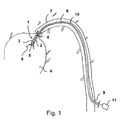
- Fig. 1 shows an axial pump 1 with a rotor 2 and a housing 3 inside a heart chamber 4 in a schematic view.
- blood is sucked through the pump 1 through openings 5, as indicated by the arrows 6.
- the blood is expelled again within a blood vessel 7 in the direction of the arrows 8, and thus the pumping function of the heart is replaced or assisted.
- the pump 1 is arranged at the distal end of a hollow catheter 8, which is inserted through the blood vessel 7 into the heart chamber 4 and protrudes the proximal end through a lock 9 from the blood vessel and ultimately from the body of the patient.
- a drive shaft 10 is provided, which is driven by means of an outside of the body arranged motor 11 at high speed, typically above 10,000 revolutions per minute.
- the rotor 2 is connected to the shaft 10 and rotates with this.
- the pump 1 has a larger diameter during operation within the heart chamber 4 than during insertion through the blood vessel 7. In particular, it may have a larger diameter than the inner diameter of the blood vessel.
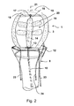
- the Fig. 2 schematically shows in enlarged form the pump, wherein the end of the hollow catheter 8 is shown in the lower region with a compression funnel 12.
- the hollow catheter 8 passes through the shaft 10, and this is rotatably mounted in a bearing 13 at the proximal end of the pump housing 3.
- the bearing can be designed so that it is configured tensile strength, so that at the shaft 10, the pump housing 3 in the compression hopper 12 at least a little bit retractable and thus simultaneously is radially compressible.
- the housing may also be retractable by means of an additional pull running through the hollow catheter.
- the shaft 10 is connected to the hub body 14 of the rotor 15, which in turn is mounted rotatably in a second bearing 17 either directly or via a shaft extension 16 at the distal end of the pump housing 3. Also this bearing can be designed tensile strength to transmit tensile forces by means of the shaft 10 and the rotor 15 to the housing.
- the bearing 17 is mounted in a strut assembly 18 of the pump housing 3, which has enough openings to allow blood or other body fluids to flow to the rotor.
- the pump housing 3 and the rotor 15 can be strongly radially compressed and stored at the distal end of the hollow catheter 8 in this. After introduction into a heart chamber, the pump can then be pushed out of the catheter 8 by some distance by means of the shaft and unfold automatically due to elastic effects.
- the pump housing 3 unfolds to the illustrated diameter, and at the same time the blades 20 are directed away from the hub body 14 away and away from the axis of rotation 21st
- the pushing out of the pump 1 from the hollow catheter 8 can be realized alternatively or in addition to the pushing movement on the shaft 10 by further trains 22, 23, which are guided closely in or on the hollow catheter and thus allow both tensile and compressive movements.
- trains 22, 23 can be attached to the outside of the patient's body at the proximal end on a manipulation ring, which can be pushed and pulled from the outside.
- the trains can be guided, for example, in guides on the outside of the hollow catheter narrow and axially displaceable.
- the pump housing 3 may consist of an open-cell foam or a closed-cell foam and thereby be designed to be elastic. However, larger cavities may also be provided there, for example by means of a tube 24, which at the proximal end with a gas reservoir or connected to a pump, aspirated or filled with a fluid to compress the pump or to expand / decompress.
- the rotor 15 With the compression movement of the housing and the rotor 15 can be compressed by radially exerted pressure on him. However, the rotor can also be compressed automatically by suction of a fluid from corresponding cavities, or its compression can be supported by such an effect at least.
- a corresponding compression and decompression effect can also be accomplished solely by pushing the pump out of the hollow catheter and pulling it into the compression nozzle 12.
- a foam material for.
- polyurethane can be made.
- larger cavities, in particular in the hub, but also in the airfoil 25, may be provided.
- Fig. 4 shows an airfoil 26 which is self-supporting, for example, may consist of a foam and is habenlos executed. For example, it is cut out of a flat material and twisted about a longitudinal axis 21 at the proximal and distal ends to produce the corresponding helical shape.
- such an airfoil may consist of a foam, cut out of a flat foam material accordingly are then placed in the helical shape and then heated to stabilize after cooling the helical shape. Thereafter, the body is stable enough to maintain the desired shape during pumping, yet can be radially compressed using a corresponding compressive force.
- FIG. 5 schematically a section of an airfoil 26 is shown, wherein it is shown that honeycomb-shaped cavities 27, which are hexagonal in cross section, with their longitudinal axes 33 are perpendicular to the airfoil surface.
- honeycomb-shaped cavities 27, which are hexagonal in cross section, with their longitudinal axes 33 are perpendicular to the airfoil surface.
- honeycomb-shaped cavities 27 differently shaped cavities are also conceivable in cross section, as these in the FIGS. 7-11 are shown. It shows Fig. 7 rectangular cavities, Fig. 8 Cavities in strand form with rounded cuboid shape, Fig. 9 Circular cylinder, Fig. 10 hexagonal honeycombs in tightest packing and Fig. 11 Octagonal honeycombs in a loosened arrangement with quadrangular spaces in cross section.
- such cavities may be aligned, for example with their longitudinal axes in the circumferential direction relative to the axis of rotation 21 of the hub.
- Fig. 6 shows in a greatly enlarged, microscopic representation of a foam 32 with closed pores 28, 29, wherein in a variant (cavity 28), the material of the walls between the pores is formed as a semi-permeable membrane.
- a membrane allows the diffusion of certain liquids, which can be used, for example, for an osmotic effect.
- the cavities / pores 28 are filled, for example, with a liquid in which a salt is dissolved in a highly concentrated state, and the foam is brought into a liquid which has a lower solution concentration, the constellation tends to bring the concentrations of both liquids closer together the solvent is diffused from the outside into the interior of the cavity 28 through the membrane 30.
- an increased osmotic pressure is generated, which can be used to inflate the cavity 28 to the shape shown in dashed lines.
- an expansion and stiffening of the foam can be realized.
- This effect can also be used specifically for larger cavities in the rotor body.
- swelling processes can also be used to expand the rotor.
- a hose 31 is shown, which symbolizes that corresponding cavities can also be filled with fluid via individual or collective supply lines or that such a fluid can be sucked out of them in order to control appropriate decompression / compression processes.
- the invention thus provides a rotor which is highly compressible, wherein for its production largely otherwise already common materials can be used, which are mostly already tested in the medical field. Despite a high possible degree of compression so that a reliable functioning of a corresponding fluid pump is guaranteed.
Landscapes
- Health & Medical Sciences (AREA)
- Engineering & Computer Science (AREA)
- Heart & Thoracic Surgery (AREA)
- Mechanical Engineering (AREA)
- Cardiology (AREA)
- Hematology (AREA)
- Anesthesiology (AREA)
- Biomedical Technology (AREA)
- Life Sciences & Earth Sciences (AREA)
- Animal Behavior & Ethology (AREA)
- General Health & Medical Sciences (AREA)
- Public Health (AREA)
- Veterinary Medicine (AREA)
- General Engineering & Computer Science (AREA)
- Vascular Medicine (AREA)
- External Artificial Organs (AREA)
- Structures Of Non-Positive Displacement Pumps (AREA)
- Rotary Pumps (AREA)
Abstract
Description
Die vorliegende Erfindung liegt auf dem Gebiet des Maschinenbaus, insbesondere der Feinwerktechnik, und bezieht sich auf Rotoren für Fluidpumpen.The present invention is in the field of mechanical engineering, in particular precision engineering, and relates to rotors for fluid pumps.
Rotationspumpen sind hinlänglich bekannt, jedoch werden diese ständig, insbesondere für Spezialanwendungen, verbessert. So sind Axialpumpen bekannt geworden, die einen in axialer Richtung Fluid fördernden Rotor in einem Gehäuse aufweisen, wobei Rotor und Gehäuse verformbar, vorteilhaft komprimierbar sind, um diese vor dem Betrieb an einen gewünschten, schwierig zugänglichen Einsatzort zu bringen und sie dort zu dekomprimieren und zu betreiben.Rotary pumps are well known, but these are constantly improved, especially for special applications. Thus, axial pumps have become known, which have a fluid-conveying rotor in an axial direction in a housing, wherein rotor and housing are deformable, advantageously compressible to bring them to a desired, difficult to access operating site before operation and to decompress it and to operate.
Solche Pumpen werden in Mikrobauform beispielsweise in der Medizin eingesetzt, um in den Körper eines Patienten, beispielsweise über eine Blutbahn, eingebracht zu werden und dort, entweder im Blutgefäß oder in einer Herzkammer, betrieben zu werden.Such pumps are used in microstructure, for example in medicine, to be introduced into the body of a patient, for example via a bloodstream to be operated there, either in the blood vessel or in a ventricle.
Die Pumpen können derart komprimiert werden, dass sie durch das Blutgefäß geschoben und dann gegebenenfalls in einem größeren Körperhohlraum dekomprimiert werden können, um den Rotor zur Entfaltung zu bringen und eine hohe Förderleistung zu erzielen.The pumps may be compressed such that they can be pushed through the blood vessel and then optionally decompressed in a larger body cavity to deploy the rotor and achieve a high delivery rate.
Ein komprimierbarer Rotor ist beispielsweise aus der
Ein anderer Rotor ist aus der
Solche Konstruktionen haben oft den Nachteil, dass die Komprimierbarkeit begrenzt ist, da beispielsweise die Nabe eines Rotors unverändert bleibt, dass aufwendige Gelenke vorgesehen werden müssen, die im Betrieb stabilisiert werden, und dass teilweise superelastische Werkstoffe verwendet werden, wie Gedächtnislegierungen, die abhängig von der Umgebungstemperatur ihre Form ändern.Such designs often have the disadvantage that the compressibility is limited, for example, the hub of a rotor remains unchanged, that complex joints must be provided, which are stabilized in operation, and that partially super-elastic materials are used, such as memory alloys, which depend on the Ambient temperature change their shape.
Diese Konstruktionen machen oft den Einsatz von Verbundwerkstoffen nötig, und es ist schwierig, beim Aufbau von Stützkonstruktionen den Fluss des zu fördernden Fluids nicht zu behindern und gegebenenfalls auch die Schädigung des Fluids weitestgehend auszuschließen. Dies ist insbesondere bei der Förderung von Blut wichtig, das hochfunktionale und auch mechanisch anfällige Bestandteile enthält.These constructions often require the use of composites, and it is difficult not to hinder the flow of the fluid to be delivered in the construction of support structures and possibly also to exclude the damage of the fluid as far as possible. This is especially important in the promotion of blood, which contains highly functional and also mechanically susceptible components.
Der vorliegenden Erfindung liegt vor dem Hintergrund des Standes der Technik die Aufgabe zugrunde, in möglichst einfacher Weise einen Rotor zu schaffen, der konstruktiv einfach aufgebaut, in hohem Maße reversibel komprimierbar und im Betrieb zuverlässig ist.The present invention is based on the background of the prior art, the task in the simplest possible way to create a rotor that is structurally simple, highly reversibly compressible and reliable in operation.
Die Aufgabe wird gemäß der Erfindung mit den Merkmalen des Patentanspruchs 1 gelöst.The object is achieved according to the invention with the features of
Der erfindungsgemäße Rotor für eine Fluidpumpe weist wenigstens ein Schaufelblatt und wenigstens einen verformbaren, mit einem Fluid gefüllten oder füllbaren Hohlraum auf.
Dadurch ergibt sich eine Volumenkompressibilität des Rotors, die an sich bei einer Kompression schon zu einer Verringerung des Rotorvolumens und gegebenenfalls des Rotordurchmessers führt. Zusätzlich können die verschiedenen Bauteile des Rotors, wie beispielsweise Schaufelblätter, noch gebogen und in Richtung der Rotorachse gedrückt werden, um den Durchmesser weiter zu verringern.The rotor for a fluid pump according to the invention has at least one airfoil and at least one deformable, filled with a fluid or fillable cavity.
This results in a volume compressibility of the rotor, which already leads to a reduction in the rotor volume and optionally the rotor diameter at a compression. Additionally, the various components of the rotor, such as airfoils, may still be bent and urged toward the rotor axis to further reduce the diameter.
Der Rotor zeichnet sich damit durch eine Materialmischung oder ein Material aus, das durch Kompression von einer ersten, geringeren Dichte bzw. einem ersten geringeren spezifischen Gewicht auf eine zweite, höhere Dichte oder ein höheres spezifisches Gewicht überführbar ist. Dabei können die Hohlräume geschlossen und mit einem Gas wie beispielsweise Luft oder Stickstoff oder einem Edelgas bzw. einem anderen bioinerten Gas gefüllt sein, das durch Druck leicht volumenkomprimierbar ist.The rotor is thus characterized by a material mixture or a material which can be converted by compression from a first, lower density or a first lower specific gravity to a second, higher density or a higher specific weight. In this case, the cavities can be closed and filled with a gas such as air or nitrogen or a noble gas or another bio-inert gas, which is easily volume-compressible by pressure.
Derartige geschlossene Hohlräume tendieren dazu, sich bei Wegfall einer äußeren Druckkraft durch die Gaselastizität wieder auszudehnen, so dass der Rotor sich, sobald er an den Einsatzort gebracht ist, selbsttätig wieder entfalten kann. Zumindest aber wird die Entfaltungsbewegung durch die Gaselastizität unterstützt.Such closed cavities tend to expand again when eliminating an external compressive force by the gas elasticity, so that the rotor, once it is brought to the site, can automatically re-unfold. At least, however, the unfolding movement is supported by the gas elasticity.
Es können zudem allerdings auch Gasleitungen zu dem Rotor vorgesehen sein, die in einem oder mehreren Hohlräumen enden und das Aufpumpen der Hohlräume aktiv erlauben. Über die gleichen Leitungen kann gegebenenfalls auch das Gas zur Komprimierung abgesaugt werden.However, it may also be provided gas lines to the rotor, which end in one or more cavities and allow the inflation of the cavities actively. If necessary, the gas can also be sucked off for compression via the same lines.
Ebenso kann mit einer Flüssigkeit verfahren werden, wenn diese in die Hohlräume eingeführt wird. Befindet sich eine Flüssigkeit in den Hohlräumen, so ist diese üblicherweise sehr viel weniger komprimierbar, jedoch kann sie durch die geeignete Wahl der Viskosität im Zusammenspiel mit den übrigen konstruktiven Teilen des Rotors eine hohe Beweglichkeit und damit Komprimierbarkeit ermöglichen und dennoch im Betrieb durch die Inkompressibilität nach Entfaltung des Rotors eine gewisse Rotorstabilität unterstützen.Likewise, it can be moved with a liquid when it is introduced into the cavities. There is a liquid in the cavities, this is usually much less compressible, but it can allow high mobility and thus compressibility by the appropriate choice of viscosity in conjunction with the other structural parts of the rotor and still in operation by the incompressibility after Unfolding the rotor support a certain rotor stability.
Die Hohlräume können auch offen gestaltet werden, wobei damit ebenfalls eine hohe Kompressibilität gegeben ist. Das Material, das die Hohlräume begrenzt, muss dann entsprechend elastisch ausgebildet sein. Dies kann zum Beispiel bei einem offenporigen Schaumstoff gegeben sein.The cavities can also be made open, which also gives a high compressibility. The material that limits the cavities must then be designed correspondingly elastic. This can be given for example in an open-cell foam.
Die Erfindung kann auch vorteilhaft dadurch ausgeführt werden, dass der/die Hohlraum/Hohlräume wenigstens teilweise von einer teildurchlässigen Membran begrenzt ist/sind.
In diesem Fall kann ein Hohlraum mit einer Flüssigkeit gefüllt sein, die zusammen mit der eingesetzten Membran und in Abhängigkeit von der Flüssigkeit, in der die Pumpe einsetzbar ist, insbesondere menschlichem Blut, aufgrund von Osmose eine Diffusion in den Hohlraum hinein zulässt, die zu einer Druckerhöhung und zu einem Aufpumpen des Rotors führt.The invention can also be carried out advantageously in that the cavity (s) is at least partially bounded by a partially permeable membrane / are.
In this case, a cavity may be filled with a liquid which, together with the membrane used and depending on the liquid in which the pump can be used, in particular human blood, due to osmosis, allows diffusion into the cavity into one Pressure increase and leads to a pumping of the rotor.
Ebenso können auch Stoffe eingesetzt werden, die nach dem Inkontakttreten mit der zu fördernden Flüssigkeit zu Schwellprozessen infolge von Aufsaugen der Flüssigkeit führen und somit über eine Volumenzunahme eine Dekomprimierung des Rotors unterstützen.Likewise, it is also possible to use substances which, after contact with the liquid to be conveyed, lead to swelling processes as a result of absorption of the liquid and thus support a decompression of the rotor via an increase in volume.
Im Falle des Osmoseprozesses bietet sich das Füllen der Hohlräume mit einem Salz oder einer Salzlösung an, deren Salzkonzentration höher ist als die der zu fördernden Flüssigkeiten.In the case of the osmosis process, the filling of the cavities with a salt or a salt solution offers, the salt concentration is higher than that of the liquids to be pumped.
Vorteilhaft kann auch vorgesehen sein, dass zumindest der überwiegende Teil der Hohlräume von festem Material des Rotors umgeben und über Öffnungen mit dem Außenbereich und/oder untereinander verbunden ist/sind. In diesem Fall kann bei der Kompression ein Fluidtransport über die Hohlräume und gegebenenfalls auch aus dem Rotor heraus geschehen, so dass die entsprechenden Hohlräume leicht vollständig komprimierbar sind.Advantageously, it can also be provided that at least the majority of the cavities are surrounded by solid material of the rotor and are connected to the outside area and / or to each other via openings. In this case, in the case of compression, a fluid transport can take place via the cavities and optionally also out of the rotor, so that the corresponding cavities are easily completely compressible.
Der Rotor kann beispielsweise teilweise aus einem porösen Material wie Schaumstoff, insbesondere Polyurethan, bestehen. Ein solcher Schaumstoff kann offen- oder geschlossenporig sein. Im Falle eines offenporigen Schaumstoffs beruht die Elastizität auf dem stützenden, die Poren umgebenden Material, das sich nach einer Komprimierung von selbst wieder in seine ursprüngliche Form bewegt, wobei das Gas oder Fluid in die Poren zurückströmen kann. Durch die begrenzten Strömungsquerschnitte der Verbindungen der Hohlräume/Poren untereinander ist eine Zeitkonstante bei der Komprimierung/Dekomprimierung in gewissen Grenzen wählbar. Diese kann dafür sorgen, dass im Betrieb der Pumpe schlagartigen Deformationen des Rotors durch ungleichmäßige mechanische Belastung entgegengewirkt wird.For example, the rotor may partially consist of a porous material such as foam, in particular polyurethane. Such a foam may be open or closed pore. In the case of an open-cell foam, the elasticity is based on the supporting material surrounding the pores, which after compression moves by itself back to its original shape, whereby the gas or fluid can flow back into the pores. Due to the limited flow cross-sections of the compounds of the cavities / pores with each other, a time constant in the compression / decompression within certain limits selectable. This can ensure that during operation of the pump sudden deformations of the rotor is counteracted by uneven mechanical load.
Die Erfindung kann vorteilhaft auch vorsehen, dass der Rotor wenigstens einen Hohlraum aufweist, der in einer ersten Richtung eine größere Ausdehnung aufweist als in den im Wesentlichen senkrecht dazu stehenden Richtungen.
Das Vorsehen derartiger anisotroper Hohlräume erlaubt bei richtiger Positionierung auch die Verwirklichung anisotroper mechanischer Eigenschaften des Rotors. Hierdurch ist es möglich, diesen radial einfach und mit geringem Kraftaufwand komprimierbar zu gestalten, ohne dass dieselbe leichte Verformbarkeit im Betrieb durch den dynamischen Widerstand des zu fördernden Fluids eintritt.The invention may also advantageously provide that the rotor has at least one cavity which has a greater extent in a first direction than in the directions substantially perpendicular thereto.
The provision of such anisotropic cavities, with proper positioning, also allows the realization of anisotropic mechanical properties of the rotor. This makes it possible to make this radially compressible and easy with little effort, without the same slight deformability occurs during operation by the dynamic resistance of the fluid to be delivered.
Im Betrieb ist damit der Rotor gegenüber den axial und in Umfangsrichtung wirkenden Kräften stabilisiert, während er einer radialen Komprimierung relativ geringe Widerstände entgegensetzt.In operation, the rotor is thus stabilized with respect to the forces acting axially and circumferentially, while offering relatively little resistance to radial compression.
Die entsprechenden Hohlräume können im Querschnitt beispielsweise rund, sechseckig, dreieckig oder viereckig ausgebildet sein und beispielsweise Strangform aufweisen, so dass ihr Querschnitt entlang ihrer Länge überall im Wesentlichen gleich ist. Hierdurch ergibt sich eine Symmetrie, die der Stabilität des Rotors dient.The corresponding cavities may, for example, be round, hexagonal, triangular or quadrangular in cross-section and, for example, have a strand shape, so that their cross-section along their length is substantially the same everywhere. hereby This results in a symmetry, which serves the stability of the rotor.
Entsprechende Hohlräume können beispielsweise besonders vorteilhaft in wenigstens einem Schaufelblatt vorgesehen sein, da diese einerseits den größten Anteil an der Durchmesserreduktion des Rotors tragen und andererseits den höchsten dynamischen Kräften im Betrieb ausgesetzt sind.Corresponding cavities, for example, can be provided particularly advantageously in at least one airfoil, since these on the one hand carry the largest share of the diameter reduction of the rotor and on the other hand are exposed to the highest dynamic forces during operation.
Dennoch kann das Schaufelblatt derart stabil ausgeführt sein, dass es selbsttragend ist und dass sogar auf eine Nabe verzichtet werden kann. Ein solches Schaufelblatt kann beispielsweise als ein wendelförmig um eine Achse gebogener flacher Körper, insbesondere aus Schaumstoff, ausgebildet sein. Beispielsweise kann zu seiner Herstellung eine Polyurethan-Schaumstoffplatte wunschgemäß in ebener Form zugeschnitten, danach um eine Achse verdreht und dann gehärtet oder versteift werden. Die Form des Schaufelblattes ist damit stabilisiert, jedoch eine elastische Komprimierbarkeit weiterhin gegeben.Nevertheless, the blade can be designed so stable that it is self-supporting and that even can be dispensed with a hub. Such an airfoil may, for example, be designed as a flat body, in particular made of foam, bent around an axis in a helical manner. For example, for its production, a polyurethane foam sheet can be cut to size as desired, then twisted about an axis and then hardened or stiffened. The shape of the airfoil is thus stabilized, but an elastic compressibility continues to exist.
Es kann jedoch auch vorgesehen sein, ein derartiges Schaufelblatt oder einen gesamten Rotor durch Spritzen eines Schaumstoffs in eine vorgefertigte Form zu erzeugen.However, it may also be provided to produce such an airfoil or an entire rotor by spraying a foam in a prefabricated form.
Die Erfindung kann auch bei mit Naben versehenen Rotoren eingesetzt werden, und in diesem Fall kann insbesondere der Nabenkörper die erfindungsgemäßen Hohlräume aufweisen bzw. wenigstens teilweise aus einem Schaumstoff hergestellt sein.The invention can also be used with rotors provided with hubs, and in this case, in particular, the hub body can have the cavities according to the invention or can be made at least partially from a foam.
Werden anisotrope Hohlräume in dem Rotor vorgesehen, so ist es vorteilhaft, diese mit der Richtung ihrer größten Stabilität entlang der Kraft/Spannungsverlaufslinien, die sich im Betrieb innerhalb des Rotors einstellen, ausgerichtet werden.If anisotropic cavities are provided in the rotor, it is advantageous to align them with the direction of their greatest stability along the force / voltage trace lines that are adjusted within the rotor during operation.
Beispielsweise können die Längsachsen von strangförmigen Hohlkörpern, wie beispielsweise Wabenkörpern, senkrecht zur Schaufelblattoberfläche ausgerichtet sein, um die in dieser Richtung bzw. Umfangsrichtung wirkenden Kräfte abzufangen.For example, the longitudinal axes of strand-like hollow bodies, such as honeycomb bodies, be aligned perpendicular to the blade surface to intercept the forces acting in this direction or circumferential direction.
Die Aufgabe, einen möglichst einfach aufgebauten Rotor zu schaffen, der in hohem Maße (insbesondere reversibel) komprimierbar ist und im Betrieb zuverlässig ist, wird außerdem durch einen komprimierbaren Rotor für eine Fluidpumpe mit wenigstens einem Schaufelblatt gelöst, wobei der Rotor so aufgebaut ist, dass er einen komprimierten und einen dekomprimierten Zustand einnehmen kann und die mittlere Dichteänderung des Rotormaterials zwischen komprimiertem und dekomprimiertem Zustand mindestens 10 % beträgt.The object to provide a rotor constructed as simple as possible, which is highly compressible (especially reversible) and reliable in operation, is also solved by a compressible rotor for a fluid pump with at least one blade, the rotor is constructed so that he can take a compressed and a decompressed state and the average density change of the rotor material between compressed and decompressed state is at least 10%.
Wichtig in Abgrenzung zum Stand der Technik ist hierbei, dass die Volumenänderung vor allem auch durch Änderungen der Dichte des Rotormaterials zustande kommt. Es handelt sich hier also nicht um bloße elastische Verformungsvorgänge, bei denen die mittlere Dichte des Rotormaterials im Wesentlichen konstant ist. Die genannte Dichteänderung ist "temperaturbereinigt", d. h., es wird die Dichteänderung bei beispielsweise 36°C warmem Rotor zugrunde gelegt für den komprimierten sowie dekomprimierten Zustand.Important in contrast to the prior art here is that the change in volume is mainly due to changes in the density of the rotor material. Thus, it is not a matter of mere elastic deformation processes in which the average density of the rotor material is substantially constant. The said density change is "temperature-adjusted", i. h., It is based on the density change in, for example, 36 ° C warm rotor for the compressed and decompressed state.
Zur Herstellung dieser Dichteänderung können die in dieser Anmeldung genannten Ansätze gewählt werden. Hierbei kommen sowohl reversible als auch irreversible Verfahren in Betracht. Dies sind z. B. osmotische Verfahren, allerdings auch Verfahren, bei denen offenporiger oder geschlossenporiger Schaumstoff Verwendung findet.To prepare this density change, the approaches mentioned in this application can be selected. Both reversible and irreversible methods come into consideration. These are z. B. osmotic process, but also methods in which open-cell or closed-cell foam is used.
Die Dichteänderung des Rotors muss nicht an allen Stellen gleichmäßig sein, beispielsweise ist es möglich, dass im Bereich einer Nabe bzw. des Schaufelblattes wegen der dort eventuell gewünschten höheren Steifigkeit eine kleinere Dichteänderung erzielt wird und im Bereich eines virtuellen "Gelenkes" zwischen Nabe und Schaufelblatt eine stärkere Kompression stattfindet.The density change of the rotor does not have to be uniform at all points, for example it is possible that a smaller density change is achieved in the region of a hub or of the airfoil because of the higher stiffness that may be desired there and in the area of a virtual "joint" between hub and airfoil a stronger compression takes place.
Die mittlere Dichteänderung des Gesamtrotors kann bevorzugt auch noch stärker sein, beispielsweise mindestens 15 %, alternativ mindestens 20 % betragen. Bezogen auf einen Kunststoff sind beispielhafte Ausgangsgrößen für die Dichte 0,01...2 g/cm3 im dekomprimierten Zustand und 0,05...3 g/cm3 im komprimierten Zustand.The average density change of the overall rotor may preferably also be even stronger, for example at least 15%, alternatively at least 20%. Based on a plastic, exemplary output quantities for the density are 0.01 ... 2 g / cm 3 in the decompressed state and 0.05 ... 3 g / cm 3 in the compressed state.
Die Erfindung bezieht sich außer auf einen Rotor der beschriebenen Art auch auf eine Fluidpumpe mit einem derartigen Rotor, bei der ein komprimierbares, den Rotor umgebendes Gehäuse vorgesehen ist.The invention relates except to a rotor of the type described also to a fluid pump with such a rotor, in which a compressible, surrounding the rotor housing is provided.
Erfindungsgemäß kann auch das Gehäuse wenigstens teilweise aus einem Material bestehen, das Hohlräume aufweist, insbesondere aus einem Schaumstoff, beispielsweise Polyurethan. Auf diese Weise kann das Gehäuse gemeinsam mit dem Rotor einfach komprimiert und dekomprimiert werden.According to the invention, the housing may also at least partially consist of a material which has cavities, in particular of a foam, for example polyurethane. In this way, the housing can be easily compressed and decompressed together with the rotor.
Im Folgenden wird die Erfindung anhand eines Ausführungsbeispiels in einer Zeichnung gezeigt und anschließend beschrieben.In the following the invention will be shown by means of an embodiment in a drawing and described below.
Dabei zeigt
- Fig. 1
- eine schematische Ansicht einer Axialpumpe im Einsatz im Körper eines Patienten,
- Fig. 2
- eine vergrößerte Ansicht einer Pumpe, teilweise im Längsschnitt,
- Fig. 3
- einen Rotor in dreidimensionaler Ansicht mit Nabe,
- Fig. 4
- einen Rotor ohne Nabe in dreidimensionaler Ansicht,
- Fig. 5
- einen Teil eines Schaufelblattes in teil- weise aufgebrochener Darstellung mit waben- förmigen Hohlräumen,
- Fig. 6
- einen Schnitt durch ein poröses Material,
- Fig. 7
- dreidimensional eine mögliche Form von Hohlräumen,
- Fig. 8
- dreidimensional eine weitere mögliche Form von Hohlräumen,
- Fig. 9
- eine Struktur mit kreiszylindrischen Hohl- räumen,
- Fig. 10
- eine Struktur mit sechseckigen wabenförmi- gen Hohlräumen in dichtester Anordnung und
- Fig. 11
- eine Struktur mit achteckigen Wabenräumen und dazwischen liegenden weiteren Hohl- räumen.
- Fig. 1
- a schematic view of an axial pump in use in the body of a patient,
- Fig. 2
- an enlarged view of a pump, partially in longitudinal section,
- Fig. 3
- a rotor in three-dimensional view with hub,
- Fig. 4
- a rotor without hub in three-dimensional view,
- Fig. 5
- a part of an airfoil in a partially broken-open representation with honeycomb cavities,
- Fig. 6
- a section through a porous material,
- Fig. 7
- three-dimensional a possible form of cavities,
- Fig. 8
- three-dimensional another possible form of cavities,
- Fig. 9
- a structure with circular cylindrical cavities,
- Fig. 10
- a structure with hexagonal honeycomb cavities in the densest arrangement and
- Fig. 11
- a structure with octagonal honeycomb spaces and additional hollow spaces in between.
Innerhalb der Herzkammer 4 wird von der Pumpe 1 durch Öffnungen 5 Blut angesaugt, wie durch die Pfeile 6 angedeutet. Das Blut wird innerhalb eines Blutgefäßes 7 in Richtung der Pfeile 8 wieder ausgestoßen, und damit wird die Pumpfunktion des Herzens ersetzt oder unterstützt.Within the
Die Pumpe 1 ist am distalen Ende eines Hohlkatheters 8 angeordnet, der durch das Blutgefäß 7 hindurch in die Herzkammer 4 eingeschoben ist und dessen proximales Ende durch eine Schleuse 9 aus dem Blutgefäß und letztlich aus dem Körper des Patienten herausragt.The
Innerhalb des Hohlkatheters 8 ist eine Antriebswelle 10 vorgesehen, die mittels eines außerhalb des Körpers angeordneten Motors 11 mit hoher Drehzahl, typisch oberhalb von 10.000 Umdrehungen pro Minute, antreibbar ist. In der Pumpe 1 ist der Rotor 2 an die Welle 10 angeschlossen und rotiert mit dieser.Within the
Die Pumpe 1 weist im Betrieb innerhalb der Herzkammer 4 einen größeren Durchmesser auf als während des Einführens durch das Blutgefäß 7. Sie kann insbesondere einen größeren Durchmesser aufweisen als den Innendurchmesser des Blutgefäßes.The
Zum Entfernen der Pumpe aus dem Körper wird diese wieder komprimiert und durch die Schleuse 9 zurückgezogen.To remove the pump from the body it is again compressed and withdrawn through the
Die
Durch den Hohlkatheter 8 hindurch verläuft die Welle 10, und diese ist in einem Lager 13 am proximalen Ende des Pumpengehäuses 3 drehbar gelagert. Die Lagerung kann so ausgeführt sein, dass sie zugfest ausgestaltet ist, so dass an der Welle 10 das Pumpengehäuse 3 in den Kompressionstrichter 12 zumindest ein Stück weit zurückziehbar und damit gleichzeitig radial komprimierbar ist. Das Gehäuse kann auch mittels eines zusätzlichen, durch den Hohlkatheter verlaufenden Zuges, zurückziehbar sein.Through the
Die Welle 10 ist mit dem Nabenkörper 14 des Rotors 15 verbunden, der seinerseits entweder direkt oder über einen Wellenfortsatz 16 am distalen Ende des Pumpengehäuses 3 abermals drehbar in einem zweiten Lager 17 gelagert ist. Auch dieses Lager kann zugfest ausgeführt sein, um Zugkräfte mittels der Welle 10 und des Rotors 15 auf das Gehäuse zu übertragen.The
Das Lager 17 ist in einer Strebenanordnung 18 des Pumpengehäuses 3 befestigt, die genug Öffnungen aufweist, um Blut oder andere Körperflüssigkeiten zum Rotor einströmen zu lassen.The
Mit 19 ist die vordere Kontur des Pumpengehäuses bezeichnet, die gitterförmig ausgestaltet ist, um einerseits beim Anstoßen der Pumpe an Körpergewebe den direkten Kontakt zum Rotor zu vermeiden und andererseits beim Ansaugen größere Partikel fernzuhalten.19 with the front contour of the pump housing is called, which is designed lattice-like, on the one hand when abutting the pump to body tissue avoid direct contact with the rotor and on the other hand to keep larger particles during suction.
Beim Einbringen der Pumpe kann zunächst das Pumpengehäuse 3 und der Rotor 15 stark radial komprimiert sein und am distalen Ende des Hohlkatheters 8 in diesem gelagert sein. Nach dem Einbringen in eine Herzkammer kann dann mittels der Welle die Pumpe ein Stück weit aus dem Katheter 8 herausgeschoben werden und sich selbsttätig aufgrund elastischer Effekte entfalten. Das Pumpengehäuse 3 entfaltet sich dabei auf den dargestellten Durchmesser, und gleichzeitig richten sich die Schaufelblätter 20 vom Nabenkörper 14 weg auf und entfernen sich von der Rotationsachse 21.When introducing the pump, first, the
Das Herausschieben der Pumpe 1 aus dem Hohlkatheter 8 kann alternativ oder zusätzlich zu der Schubbewegung über die Welle 10 auch durch weitere Züge 22, 23 realisiert werden, die eng im oder an dem Hohlkatheter geführt sind und damit sowohl Zug- als auch Druckbewegungen zulassen. Diese Züge 22, 23 können am proximalen Ende außerhalb des Patientenkörpers an einem Manipulationsring befestigt werden, der von außen geschoben und gezogen werden kann. Die Züge können beispielsweise in Führungen an der Außenseite des Hohlkatheters eng und axial verschiebbar geführt sein.The pushing out of the
Das Pumpengehäuse 3 kann aus einem offenporigen Schaumstoff oder einem geschlossenporigen Schaumstoff bestehen und hierdurch elastisch ausgeführt sein. Es können dort jedoch auch größere Hohlräume vorgesehen sein, die beispielsweise mittels eines Schlauches 24, der am proximalen Ende mit einem Gasreservoir oder einer Pumpe verbunden ist, abgesaugt oder mit einem Fluid angefüllt werden, um die Pumpe zu komprimieren oder zu expandieren/dekomprimieren.The
Mit der Kompressionsbewegung des Gehäuses kann auch der Rotor 15 durch radial auf ihn ausgeübten Druck komprimiert werden. Der Rotor kann jedoch auch selbständig ebenfalls durch Absaugen eines Fluids aus entsprechenden Hohlräumen komprimiert werden, oder seine Kompression kann durch einen derartigen Effekt zumindest unterstützt werden.With the compression movement of the housing and the
Ein entsprechender Kompressions- und Dekompressionseffekt kann jedoch auch allein durch das Herausschieben der Pumpe aus dem Hohlkatheter und das Einziehen in den Kompressionsstutzen 12 bewerkstelligt werden.However, a corresponding compression and decompression effect can also be accomplished solely by pushing the pump out of the hollow catheter and pulling it into the
In der
In der
Anstelle der wabenförmigen Hohlräume 27 sind auch im Querschnitt anders geformte Hohlräume denkbar, wie diese in den
Innerhalb eines etwa vorhandenen Nabenkörpers können derartige Hohlräume beispielsweise mit ihren Längsachsen in Umfangsrichtung gegenüber der Rotationsachse 21 der Nabe ausgerichtet sein.Within an approximately existing hub body such cavities may be aligned, for example with their longitudinal axes in the circumferential direction relative to the axis of
Eine solche Membran lässt die Diffusion bestimmter Flüssigkeiten zu, was beispielsweise für einen osmotischen Effekt genutzt werden kann. Werden die Hohlräume/Poren 28 beispielsweise mit einer Flüssigkeit gefüllt, in der hochkonzentriert ein Salz gelöst ist, und wird der Schaumstoff in eine Flüssigkeit gebracht, die eine geringere Lösungskonzentration aufweist, so tendiert die Konstellation dazu, die Konzentrationen beider Flüssigkeiten dadurch aneinander anzunähern, dass das Lösungsmittel von außen in das Innere das Hohlraums 28 durch die Membran 30 eindiffundiert. Hierdurch wird ein erhöhter osmotischer Druck erzeugt, der zum Aufpumpen des Hohlraums 28 bis in die gestrichelt dargestellte Form genutzt werden kann. Hierdurch kann eine Expansion und Versteifung des Schaumstoffs realisiert werden.
Such a membrane allows the diffusion of certain liquids, which can be used, for example, for an osmotic effect. If the cavities / pores 28 are filled, for example, with a liquid in which a salt is dissolved in a highly concentrated state, and the foam is brought into a liquid which has a lower solution concentration, the constellation tends to bring the concentrations of both liquids closer together the solvent is diffused from the outside into the interior of the
Dieser Effekt kann auch für größere Hohlräume im Rotorkörper gezielt genutzt werden. Alternativ können auch Quellvorgänge zur Expansion des Rotors genutzt werden.This effect can also be used specifically for larger cavities in the rotor body. Alternatively, swelling processes can also be used to expand the rotor.
Im Zusammenhang mit dem Hohlraum 29 ist ein Schlauch 31 dargestellt, der symbolisiert, dass entsprechende Hohlräume auch über einzelne oder kollektive Zuleitungen mit einem Fluid gefüllt werden können oder dass ein solches Fluid aus ihnen abgesaugt werden kann, um entsprechende Dekompressions-/Kompressionsvorgänge zu steuern.In connection with the
Die Erfindung schafft somit einen Rotor, der in hohem Maße komprimierbar ist, wobei zu seiner Herstellung weitgehend anderweitig bereits übliche Materialien verwendet werden können, die größtenteils auch im medizinischen Bereich schon erprobt sind. Trotz eines hohen möglichen Kompressionsgrades wird damit ein zuverlässiges Funktionieren einer entsprechenden Fluidpumpe gewährleistet.The invention thus provides a rotor which is highly compressible, wherein for its production largely otherwise already common materials can be used, which are mostly already tested in the medical field. Despite a high possible degree of compression so that a reliable functioning of a corresponding fluid pump is guaranteed.
Claims (16)
Priority Applications (14)
| Application Number | Priority Date | Filing Date | Title |
|---|---|---|---|
| EP18195089.0A EP3441616B1 (en) | 2009-09-22 | 2009-09-22 | Compressible rotor for a fluid pump |
| DK18195089.0T DK3441616T3 (en) | 2009-09-22 | 2009-09-22 | COMPRESSIBLE ROTOR FOR A FLUID PUMP |
| EP23159838.4A EP4215752A1 (en) | 2009-09-22 | 2009-09-22 | Compressible rotor for a fluid pump |
| EP09075438.3A EP2299119B1 (en) | 2009-09-22 | 2009-09-22 | Inflatable rotor for a fluid pump |
| DE112010003746T DE112010003746T5 (en) | 2009-09-22 | 2010-09-22 | Compressible rotor for a fluid pump |
| US13/261,213 US9416783B2 (en) | 2009-09-22 | 2010-09-22 | Compressible rotor for a fluid pump |
| CN201610352087.8A CN106039443B (en) | 2009-09-22 | 2010-09-22 | Expandable rotating element for fluid pump |
| CN201080042127.XA CN102639874B (en) | 2009-09-22 | 2010-09-22 | Expandable rotating element for fluid pump |
| CN201610353540.7A CN106063952B (en) | 2009-09-22 | 2010-09-22 | Expandable rotating element for fluid pump |
| PCT/EP2010/005871 WO2011035929A2 (en) | 2009-09-22 | 2010-09-22 | Compressible rotor for a fluid pump |
| US15/236,757 US20160348688A1 (en) | 2009-09-22 | 2016-08-15 | Compressible rotor for a fluid pump |
| US16/688,187 US11421701B2 (en) | 2009-09-22 | 2019-11-19 | Compressible rotor for a fluid pump |
| US17/865,064 US11773861B2 (en) | 2009-09-22 | 2022-07-14 | Compressible rotor for a fluid pump |
| US18/239,169 US20240052845A1 (en) | 2009-09-22 | 2023-08-29 | Compressible rotor for a fluid pump |
Applications Claiming Priority (1)
| Application Number | Priority Date | Filing Date | Title |
|---|---|---|---|
| EP09075438.3A EP2299119B1 (en) | 2009-09-22 | 2009-09-22 | Inflatable rotor for a fluid pump |
Related Child Applications (3)
| Application Number | Title | Priority Date | Filing Date |
|---|---|---|---|
| EP23159838.4A Division EP4215752A1 (en) | 2009-09-22 | 2009-09-22 | Compressible rotor for a fluid pump |
| EP18195089.0A Division-Into EP3441616B1 (en) | 2009-09-22 | 2009-09-22 | Compressible rotor for a fluid pump |
| EP18195089.0A Division EP3441616B1 (en) | 2009-09-22 | 2009-09-22 | Compressible rotor for a fluid pump |
Publications (2)
| Publication Number | Publication Date |
|---|---|
| EP2299119A1 true EP2299119A1 (en) | 2011-03-23 |
| EP2299119B1 EP2299119B1 (en) | 2018-11-07 |
Family
ID=41682290
Family Applications (3)
| Application Number | Title | Priority Date | Filing Date |
|---|---|---|---|
| EP23159838.4A Pending EP4215752A1 (en) | 2009-09-22 | 2009-09-22 | Compressible rotor for a fluid pump |
| EP18195089.0A Active EP3441616B1 (en) | 2009-09-22 | 2009-09-22 | Compressible rotor for a fluid pump |
| EP09075438.3A Active EP2299119B1 (en) | 2009-09-22 | 2009-09-22 | Inflatable rotor for a fluid pump |
Family Applications Before (2)
| Application Number | Title | Priority Date | Filing Date |
|---|---|---|---|
| EP23159838.4A Pending EP4215752A1 (en) | 2009-09-22 | 2009-09-22 | Compressible rotor for a fluid pump |
| EP18195089.0A Active EP3441616B1 (en) | 2009-09-22 | 2009-09-22 | Compressible rotor for a fluid pump |
Country Status (6)
| Country | Link |
|---|---|
| US (5) | US9416783B2 (en) |
| EP (3) | EP4215752A1 (en) |
| CN (3) | CN106063952B (en) |
| DE (1) | DE112010003746T5 (en) |
| DK (1) | DK3441616T3 (en) |
| WO (1) | WO2011035929A2 (en) |
Cited By (16)
| Publication number | Priority date | Publication date | Assignee | Title |
|---|---|---|---|---|
| CN111032113A (en) * | 2017-08-23 | 2020-04-17 | Ecp发展有限责任公司 | Apparatus for compressing compressible components of a catheter pump |
| US10722631B2 (en) | 2018-02-01 | 2020-07-28 | Shifamed Holdings, Llc | Intravascular blood pumps and methods of use and manufacture |
| EP3852245A1 (en) | 2013-10-11 | 2021-07-21 | ECP Entwicklungsgesellschaft mbH | Compressible motor, implanting assembly and method for positioning the motor |
| US11185677B2 (en) | 2017-06-07 | 2021-11-30 | Shifamed Holdings, Llc | Intravascular fluid movement devices, systems, and methods of use |
| US11511103B2 (en) | 2017-11-13 | 2022-11-29 | Shifamed Holdings, Llc | Intravascular fluid movement devices, systems, and methods of use |
| US11648392B2 (en) | 2016-11-23 | 2023-05-16 | Magenta Medical Ltd. | Blood pumps |
| US11648391B2 (en) | 2013-03-13 | 2023-05-16 | Magenta Medical Ltd. | Blood pump |
| US11648387B2 (en) | 2015-05-18 | 2023-05-16 | Magenta Medical Ltd. | Blood pump |
| US11654275B2 (en) | 2019-07-22 | 2023-05-23 | Shifamed Holdings, Llc | Intravascular blood pumps with struts and methods of use and manufacture |
| US11666747B2 (en) | 2019-01-24 | 2023-06-06 | Magenta Medical Ltd. | Manufacturing an impeller |
| US11684275B2 (en) | 2018-01-10 | 2023-06-27 | Magenta Medical Ltd. | Distal tip element for blood pump |
| US11724089B2 (en) | 2019-09-25 | 2023-08-15 | Shifamed Holdings, Llc | Intravascular blood pump systems and methods of use and control thereof |
| US11839540B2 (en) | 2012-06-06 | 2023-12-12 | Magenta Medical Ltd | Vena-caval apparatus and methods |
| US11839754B2 (en) | 2016-10-25 | 2023-12-12 | Magenta Medical Ltd | Ventricular assist device |
| US11883274B2 (en) | 2013-03-13 | 2024-01-30 | Magenta Medical Ltd. | Vena-caval blood pump |
| US11964145B2 (en) | 2019-07-12 | 2024-04-23 | Shifamed Holdings, Llc | Intravascular blood pumps and methods of manufacture and use |
Families Citing this family (66)
| Publication number | Priority date | Publication date | Assignee | Title |
|---|---|---|---|---|
| US7393181B2 (en) | 2004-09-17 | 2008-07-01 | The Penn State Research Foundation | Expandable impeller pump |
| JP2009530041A (en) | 2006-03-23 | 2009-08-27 | ザ・ペン・ステート・リサーチ・ファンデーション | Cardiac assist device with expandable impeller pump |
| EP2194278A1 (en) | 2008-12-05 | 2010-06-09 | ECP Entwicklungsgesellschaft mbH | Fluid pump with a rotor |
| EP2216059A1 (en) | 2009-02-04 | 2010-08-11 | ECP Entwicklungsgesellschaft mbH | Catheter device with a catheter and an actuation device |
| EP2229965A1 (en) | 2009-03-18 | 2010-09-22 | ECP Entwicklungsgesellschaft mbH | Fluid pump with particular form of a rotor blade |
| EP2246078A1 (en) | 2009-04-29 | 2010-11-03 | ECP Entwicklungsgesellschaft mbH | Shaft assembly with a shaft which moves within a fluid-filled casing |
| EP2248544A1 (en) | 2009-05-05 | 2010-11-10 | ECP Entwicklungsgesellschaft mbH | Fluid pump with variable circumference, particularly for medical use |
| EP2266640A1 (en) | 2009-06-25 | 2010-12-29 | ECP Entwicklungsgesellschaft mbH | Compressible and expandable turbine blade for a fluid pump |
| EP2282070B1 (en) | 2009-08-06 | 2012-10-17 | ECP Entwicklungsgesellschaft mbH | Catheter device with a coupling device for a drive device |
| EP2298372A1 (en) | 2009-09-22 | 2011-03-23 | ECP Entwicklungsgesellschaft mbH | Rotor for an axial pump for transporting a fluid |
| DK3441616T3 (en) | 2009-09-22 | 2023-05-30 | Ecp Entw Mbh | COMPRESSIBLE ROTOR FOR A FLUID PUMP |
| EP2298373A1 (en) | 2009-09-22 | 2011-03-23 | ECP Entwicklungsgesellschaft mbH | Fluid pump with at least one turbine blade and a seating device |
| EP2298371A1 (en) | 2009-09-22 | 2011-03-23 | ECP Entwicklungsgesellschaft mbH | Function element, in particular fluid pump with a housing and a transport element |
| EP2314331B1 (en) | 2009-10-23 | 2013-12-11 | ECP Entwicklungsgesellschaft mbH | Catheter pump arrangement and flexible shaft arrangement with a cable core |
| EP2314330A1 (en) | 2009-10-23 | 2011-04-27 | ECP Entwicklungsgesellschaft mbH | Flexible shaft arrangement |
| EP2338539A1 (en) | 2009-12-23 | 2011-06-29 | ECP Entwicklungsgesellschaft mbH | Pump device with a detection device |
| EP2338540A1 (en) | 2009-12-23 | 2011-06-29 | ECP Entwicklungsgesellschaft mbH | Delivery blade for a compressible rotor |
| EP2338541A1 (en) | 2009-12-23 | 2011-06-29 | ECP Entwicklungsgesellschaft mbH | Radial compressible and expandable rotor for a fluid pump |
| EP2347778A1 (en) | 2010-01-25 | 2011-07-27 | ECP Entwicklungsgesellschaft mbH | Fluid pump with a radially compressible rotor |
| EP2363157A1 (en) | 2010-03-05 | 2011-09-07 | ECP Entwicklungsgesellschaft mbH | Device for exerting mechanical force on a medium, in particular fluid pump |
| EP2388029A1 (en) | 2010-05-17 | 2011-11-23 | ECP Entwicklungsgesellschaft mbH | Pump array |
| EP2399639A1 (en) | 2010-06-25 | 2011-12-28 | ECP Entwicklungsgesellschaft mbH | System for introducing a pump |
| EP2407186A1 (en) | 2010-07-15 | 2012-01-18 | ECP Entwicklungsgesellschaft mbH | Rotor for a pump, produced with an initial elastic material |
| EP2407185A1 (en) | 2010-07-15 | 2012-01-18 | ECP Entwicklungsgesellschaft mbH | Radial compressible and expandable rotor for a pump with a turbine blade |
| EP2407187A3 (en) | 2010-07-15 | 2012-06-20 | ECP Entwicklungsgesellschaft mbH | Blood pump for invasive application within the body of a patient |
| EP2422735A1 (en) | 2010-08-27 | 2012-02-29 | ECP Entwicklungsgesellschaft mbH | Implantable blood transportation device, manipulation device and coupling device |
| WO2012094641A2 (en) | 2011-01-06 | 2012-07-12 | Thoratec Corporation | Percutaneous heart pump |
| EP2497521A1 (en) | 2011-03-10 | 2012-09-12 | ECP Entwicklungsgesellschaft mbH | Push device for axial insertion of a string-shaped, flexible body |
| EP2564771A1 (en) | 2011-09-05 | 2013-03-06 | ECP Entwicklungsgesellschaft mbH | Medicinal product with a functional element for invasive use in the body of a patient |
| US8926492B2 (en) | 2011-10-11 | 2015-01-06 | Ecp Entwicklungsgesellschaft Mbh | Housing for a functional element |
| AU2012345572C1 (en) | 2011-12-03 | 2018-05-31 | Indiana University Research And Technology Corporation | Cavopulmonary viscous impeller assist device and method |
| US9872947B2 (en) | 2012-05-14 | 2018-01-23 | Tc1 Llc | Sheath system for catheter pump |
| GB2504176A (en) | 2012-05-14 | 2014-01-22 | Thoratec Corp | Collapsible impeller for catheter pump |
| US9327067B2 (en) | 2012-05-14 | 2016-05-03 | Thoratec Corporation | Impeller for catheter pump |
| US8721517B2 (en) | 2012-05-14 | 2014-05-13 | Thoratec Corporation | Impeller for catheter pump |
| US9446179B2 (en) | 2012-05-14 | 2016-09-20 | Thoratec Corporation | Distal bearing support |
| US9358329B2 (en) | 2012-07-03 | 2016-06-07 | Thoratec Corporation | Catheter pump |
| EP4186557A1 (en) | 2012-07-03 | 2023-05-31 | Tc1 Llc | Motor assembly for catheter pump |
| US9421311B2 (en) | 2012-07-03 | 2016-08-23 | Thoratec Corporation | Motor assembly for catheter pump |
| EP2745869A1 (en) * | 2012-12-21 | 2014-06-25 | ECP Entwicklungsgesellschaft mbH | Sluice assembly for the introduction of a cord-like body, in particular of a catheter, into a patient |
| EP2968718B1 (en) | 2013-03-13 | 2021-04-21 | Tc1 Llc | Fluid handling system |
| US11033728B2 (en) | 2013-03-13 | 2021-06-15 | Tc1 Llc | Fluid handling system |
| US11077294B2 (en) | 2013-03-13 | 2021-08-03 | Tc1 Llc | Sheath assembly for catheter pump |
| US9308302B2 (en) | 2013-03-15 | 2016-04-12 | Thoratec Corporation | Catheter pump assembly including a stator |
| WO2014143593A1 (en) | 2013-03-15 | 2014-09-18 | Thoratec Corporation | Catheter pump assembly including a stator |
| WO2015160979A1 (en) | 2014-04-15 | 2015-10-22 | Thoratec Corporation | Catheter pump with access ports |
| WO2015160942A1 (en) | 2014-04-15 | 2015-10-22 | Thoratec Corporation | Catheter pump with off-set motor position |
| WO2015160990A1 (en) | 2014-04-15 | 2015-10-22 | Thoratec Corporation | Catheter pump introducer systems and methods |
| WO2015160943A1 (en) | 2014-04-15 | 2015-10-22 | Thoratec Corporation | Sensors for catheter pumps |
| US10449279B2 (en) | 2014-08-18 | 2019-10-22 | Tc1 Llc | Guide features for percutaneous catheter pump |
| EP3598986B1 (en) | 2015-01-22 | 2021-02-17 | Tc1 Llc | Motor assembly with heat exchanger for catheter pump |
| WO2016118777A1 (en) | 2015-01-22 | 2016-07-28 | Thoratec Corporation | Reduced rotational mass motor assembly for catheter pump |
| WO2016118784A1 (en) | 2015-01-22 | 2016-07-28 | Thoratec Corporation | Attachment mechanisms for motor of catheter pump |
| US10350341B2 (en) | 2015-03-20 | 2019-07-16 | Drexel University | Impellers, blood pumps, and methods of treating a subject |
| US9907890B2 (en) | 2015-04-16 | 2018-03-06 | Tc1 Llc | Catheter pump with positioning brace |
| US11160970B2 (en) | 2016-07-21 | 2021-11-02 | Tc1 Llc | Fluid seals for catheter pump motor assembly |
| EP3808401A1 (en) | 2016-07-21 | 2021-04-21 | Tc1 Llc | Gas-filled chamber for catheter pump motor assembly |
| US10179197B2 (en) * | 2016-11-21 | 2019-01-15 | Cardiobridge Gmbh | Catheter pump with a pump head for insertion into the aorta |
| DE102018201030A1 (en) | 2018-01-24 | 2019-07-25 | Kardion Gmbh | Magnetic coupling element with magnetic bearing function |
| DE102018211327A1 (en) | 2018-07-10 | 2020-01-16 | Kardion Gmbh | Impeller for an implantable vascular support system |
| US11219753B2 (en) * | 2018-07-30 | 2022-01-11 | Cardiovascular Systems, Inc. | Intravascular pump with expandable and collapsible inlet region and methods thereof |
| US20200288988A1 (en) | 2019-03-14 | 2020-09-17 | Abiomed, Inc. | Blood Flow Rate Measurement System |
| WO2021026469A1 (en) * | 2019-08-07 | 2021-02-11 | Daniel Hildebrand | Catheter blood pumps and impellers |
| CN110812552B (en) * | 2019-10-28 | 2021-05-25 | 江苏大学 | Miniature ventricle auxiliary device with foldable impeller |
| DE102020102474A1 (en) | 2020-01-31 | 2021-08-05 | Kardion Gmbh | Pump for conveying a fluid and method for manufacturing a pump |
| EP4252827A3 (en) * | 2021-10-11 | 2024-01-10 | Magenta Medical Ltd. | Ventricular assist device |
Citations (5)
| Publication number | Priority date | Publication date | Assignee | Title |
|---|---|---|---|---|
| US6533716B1 (en) * | 1998-03-07 | 2003-03-18 | Thomas Schmitz-Rode | Self-deploying axial-flow pump introduced intravascularly for temporary cardiac support |
| US20030135086A1 (en) * | 2001-11-19 | 2003-07-17 | University Of Medicine And Dentistry Of New Jersey | Temporary blood circulation assist device |
| US6860713B2 (en) | 2002-11-27 | 2005-03-01 | Nidec Corporation | Fan with collapsible blades, redundant fan system, and related method |
| US20060062672A1 (en) * | 2004-09-17 | 2006-03-23 | Mcbride Mark W | Expandable impeller pump |
| WO2009029959A2 (en) * | 2007-08-29 | 2009-03-05 | Medical Value Partners, Llc | Article comprising an impeller |
Family Cites Families (221)
| Publication number | Priority date | Publication date | Assignee | Title |
|---|---|---|---|---|
| DE1124299B (en) | 1960-09-01 | 1962-02-22 | Cvjetko Galic | Condensate processing device for carburettor engines |
| FR1512372A (en) * | 1966-12-19 | 1968-02-09 | Deformable membrane by internal action | |
| US3510229A (en) | 1968-07-23 | 1970-05-05 | Maytag Co | One-way pump |
| US3568659A (en) | 1968-09-24 | 1971-03-09 | James N Karnegis | Disposable percutaneous intracardiac pump and method of pumping blood |
| US3674019A (en) * | 1970-10-23 | 1972-07-04 | Grant Airmass Corp | Dual layer cellular inflatable pad |
| US3995631A (en) * | 1971-01-13 | 1976-12-07 | Alza Corporation | Osmotic dispenser with means for dispensing active agent responsive to osmotic gradient |
| CH538410A (en) | 1971-02-17 | 1973-06-30 | L Somers S Brice | Flexible device for the transport of granular, powdery or fluid products |
| DE2113986A1 (en) | 1971-03-23 | 1972-09-28 | Svu Textilni | Artificial heart machine - with ptfe or similar inert plastic coated parts,as intracorperal replacement |
| SU400331A1 (en) | 1971-07-06 | 1973-10-01 | ||
| US3760984A (en) * | 1971-09-29 | 1973-09-25 | Alza Corp | Osmotically powered agent dispensing device with filling means |
| US4014317A (en) | 1972-02-18 | 1977-03-29 | The United States Of America As Represented By The Department Of Health, Education And Welfare | Multipurpose cardiocirculatory assist cannula and methods of use thereof |
| US3812812A (en) | 1973-06-25 | 1974-05-28 | M Hurwitz | Trolling propeller with self adjusting hydrodynamic spoilers |
| DE2340755B2 (en) * | 1973-08-11 | 1975-09-18 | Horst Dr.-Ing. 5100 Aachen Chmiel | Blood pump |
| US4207028A (en) | 1979-06-12 | 1980-06-10 | Ridder Sven O | Extendable and retractable propeller for watercraft |
| US4559951A (en) | 1982-11-29 | 1985-12-24 | Cardiac Pacemakers, Inc. | Catheter assembly |
| US4563181A (en) | 1983-02-18 | 1986-01-07 | Mallinckrodt, Inc. | Fused flexible tip catheter |
| US4727027A (en) * | 1983-05-02 | 1988-02-23 | Diamond Scientific Co. | Photochemical decontamination treatment of whole blood or blood components |
| US4686982A (en) | 1985-06-19 | 1987-08-18 | John Nash | Spiral wire bearing for rotating wire drive catheter |
| US4679558A (en) | 1985-08-12 | 1987-07-14 | Intravascular Surgical Instruments, Inc. | Catheter based surgical methods and apparatus therefor |
| US4801243A (en) | 1985-12-28 | 1989-01-31 | Bird-Johnson Company | Adjustable diameter screw propeller |
| DE3601691A1 (en) * | 1986-01-17 | 1987-07-23 | Simon Jochen | HOLLOW BODY WITH FLEXIBLE COVER |
| DE3621350A1 (en) * | 1986-06-26 | 1988-01-14 | Bonzel Tassilo | DILATATION CATHETER WITH AN EXPANDABLE BALLOON |
| US4747821A (en) | 1986-10-22 | 1988-05-31 | Intravascular Surgical Instruments, Inc. | Catheter with high speed moving working head |
| US4753221A (en) | 1986-10-22 | 1988-06-28 | Intravascular Surgical Instruments, Inc. | Blood pumping catheter and method of use |
| US4749376A (en) | 1986-10-24 | 1988-06-07 | Intravascular Surgical Instruments, Inc. | Reciprocating working head catheter |
| US4817613A (en) | 1987-07-13 | 1989-04-04 | Devices For Vascular Intervention, Inc. | Guiding catheter |
| US5154705A (en) | 1987-09-30 | 1992-10-13 | Lake Region Manufacturing Co., Inc. | Hollow lumen cable apparatus |
| US4797312A (en) * | 1987-09-30 | 1989-01-10 | Kent Sherwood | Foam-honeycomb article and method |
| US5061256A (en) | 1987-12-07 | 1991-10-29 | Johnson & Johnson | Inflow cannula for intravascular blood pumps |
| US5183384A (en) | 1988-05-16 | 1993-02-02 | Trumbly Joe H | Foldable propeller assembly |
| US5011469A (en) | 1988-08-29 | 1991-04-30 | Shiley, Inc. | Peripheral cardiopulmonary bypass and coronary reperfusion system |
| US4919647A (en) | 1988-10-13 | 1990-04-24 | Kensey Nash Corporation | Aortically located blood pumping catheter and method of use |
| US4957504A (en) | 1988-12-02 | 1990-09-18 | Chardack William M | Implantable blood pump |
| US4969865A (en) | 1989-01-09 | 1990-11-13 | American Biomed, Inc. | Helifoil pump |
| US5112292A (en) | 1989-01-09 | 1992-05-12 | American Biomed, Inc. | Helifoil pump |
| US4944722A (en) | 1989-02-23 | 1990-07-31 | Nimbus Medical, Inc. | Percutaneous axial flow blood pump |
| US5052404A (en) | 1989-03-02 | 1991-10-01 | The Microspring Company, Inc. | Torque transmitter |
| US4995857A (en) | 1989-04-07 | 1991-02-26 | Arnold John R | Left ventricular assist device and method for temporary and permanent procedures |
| US5042984A (en) | 1989-08-17 | 1991-08-27 | Kensey Nash Corporation | Catheter with working head having selectable impacting surfaces and method of using the same |
| US5097849A (en) | 1989-08-17 | 1992-03-24 | Kensey Nash Corporation | Method of use of catheter with working head having selectable impacting surfaces |
| US5040944A (en) | 1989-09-11 | 1991-08-20 | Cook Einar P | Pump having impeller rotational about convoluted stationary member |
| GB8927282D0 (en) * | 1989-12-01 | 1990-01-31 | Univ Strathclyde | Vascular surgical devices |
| GB2239675A (en) | 1989-12-05 | 1991-07-10 | Man Fai Shiu | Pump for pumping liquid |
| US5118264A (en) | 1990-01-11 | 1992-06-02 | The Cleveland Clinic Foundation | Purge flow control in rotary blood pumps |
| US5145333A (en) | 1990-03-01 | 1992-09-08 | The Cleveland Clinic Foundation | Fluid motor driven blood pump |
| JPH0636821B2 (en) | 1990-03-08 | 1994-05-18 | 健二 山崎 | Implantable auxiliary artificial heart |
| US5108411A (en) | 1990-03-28 | 1992-04-28 | Cardiovascular Imaging Systems, Inc. | Flexible catheter drive cable |
| US5163910A (en) | 1990-04-10 | 1992-11-17 | Mayo Foundation For Medical Education And Research | Intracatheter perfusion pump apparatus and method |
| US5092844A (en) * | 1990-04-10 | 1992-03-03 | Mayo Foundation For Medical Education And Research | Intracatheter perfusion pump apparatus and method |
| US5813405A (en) | 1990-04-18 | 1998-09-29 | Cordis Corporation | Snap-in connection assembly for extension guidewire system |
| US5191888A (en) | 1990-04-18 | 1993-03-09 | Cordis Corporation | Assembly of an extension guidewire and an alignment tool for same |
| US5117838A (en) | 1990-04-18 | 1992-06-02 | Cordis Corporation | Rotating guidewire extension system |
| US5113872A (en) | 1990-04-18 | 1992-05-19 | Cordis Corporation | Guidewire extension system with connectors |
| US5154724A (en) * | 1990-05-14 | 1992-10-13 | Andrews Winston A | Atherectomy catheter |
| ES2020787A6 (en) | 1990-07-20 | 1991-09-16 | Figuera Aymerich Diego | Intra-ventricular expansible assist pump |
| US5439444A (en) * | 1991-01-28 | 1995-08-08 | Corpak, Inc. | Pre-formed member for percutaneous catheter |
| US5308325A (en) * | 1991-01-28 | 1994-05-03 | Corpak, Inc. | Retention balloon for percutaneous catheter |
| US5192286A (en) | 1991-07-26 | 1993-03-09 | Regents Of The University Of California | Method and device for retrieving materials from body lumens |
| US5188621A (en) | 1991-08-26 | 1993-02-23 | Target Therapeutics Inc. | Extendable guidewire assembly |
| IT1251758B (en) | 1991-11-05 | 1995-05-23 | Roberto Parravicini | VENTRICULAR PUMPING ASSISTANCE ELEMENT, WITH EXTERNAL DRIVE |
| US5201679A (en) | 1991-12-13 | 1993-04-13 | Attwood Corporation | Marine propeller with breakaway hub |
| US5271415A (en) | 1992-01-28 | 1993-12-21 | Baxter International Inc. | Guidewire extension system |
| US5470320A (en) * | 1992-04-10 | 1995-11-28 | Tiefenbrun; Jonathan | Method and related device for obtaining access to a hollow organ |
| US6346120B1 (en) | 1992-06-23 | 2002-02-12 | Sun Medical Technology Research Corporation | Auxiliary artificial heart of an embedded type |
| US5300112A (en) | 1992-07-14 | 1994-04-05 | Aai Corporation | Articulated heart pump |
| US5383840A (en) * | 1992-07-28 | 1995-01-24 | Vascor, Inc. | Biocompatible ventricular assist and arrhythmia control device including cardiac compression band-stay-pad assembly |
| US5676651A (en) | 1992-08-06 | 1997-10-14 | Electric Boat Corporation | Surgically implantable pump arrangement and method for pumping body fluids |
| SE501215C2 (en) * | 1992-09-02 | 1994-12-12 | Oeyvind Reitan | catheter Pump |
| US5376114A (en) | 1992-10-30 | 1994-12-27 | Jarvik; Robert | Cannula pumps for temporary cardiac support and methods of their application and use |
| US5403280A (en) * | 1993-02-16 | 1995-04-04 | Wang; James C. | Inflatable perfusion catheter |
| US5308356A (en) * | 1993-02-25 | 1994-05-03 | Blackshear Jr Perry L | Passive perfusion angioplasty catheter |
| US5365943A (en) | 1993-03-12 | 1994-11-22 | C. R. Bard, Inc. | Anatomically matched steerable PTCA guidewire |
| JPH06346917A (en) | 1993-06-03 | 1994-12-20 | Shicoh Eng Co Ltd | Pressure-proof water-proof sealing system using unidirectional dynamic pressure bearing |
| US5368438A (en) | 1993-06-28 | 1994-11-29 | Baxter International Inc. | Blood pump |
| US5720300A (en) | 1993-11-10 | 1998-02-24 | C. R. Bard, Inc. | High performance wires for use in medical devices and alloys therefor |
| DK145093D0 (en) | 1993-12-23 | 1993-12-23 | Gori 1902 As | PROPELLER |
| US5531789A (en) | 1993-12-24 | 1996-07-02 | Sun Medical Technology Research Corporation | Sealing system of an artificial internal organ |
| US5599306A (en) * | 1994-04-01 | 1997-02-04 | Localmed, Inc. | Method and apparatus for providing external perfusion lumens on balloon catheters |
| US5613935A (en) | 1994-12-16 | 1997-03-25 | Jarvik; Robert | High reliability cardiac assist system |
| KR0173342B1 (en) * | 1995-07-27 | 1999-02-18 | 이대성 | Fine processing method of cardiocle type and blated cardioid type casing curve for eccentric rotor vane pump |
| EP1044624B1 (en) | 1995-08-28 | 2003-12-10 | Matsushita Electric Works, Ltd. | Hand-held depilating device |
| DE19535781C2 (en) | 1995-09-26 | 1999-11-11 | Fraunhofer Ges Forschung | Device for active flow support of body fluids |
| DE69531399T2 (en) | 1995-10-16 | 2004-06-09 | Sun Medical Technology Research Corp., Suwa | artificial heart |
| US5701911A (en) | 1996-04-05 | 1997-12-30 | Medtronic, Inc. | Guide wire extension docking system |
| US6254359B1 (en) | 1996-05-10 | 2001-07-03 | The United States Of America As Represented By The Administrator Of The National Aeronautics And Space Administration | Method for providing a jewel bearing for supporting a pump rotor shaft |
| IL118352A0 (en) | 1996-05-21 | 1996-09-12 | Sudai Amnon | Apparatus and methods for revascularization |
| US5820571A (en) | 1996-06-24 | 1998-10-13 | C. R. Bard, Inc. | Medical backloading wire |
| US6015272A (en) | 1996-06-26 | 2000-01-18 | University Of Pittsburgh | Magnetically suspended miniature fluid pump and method of designing the same |
| US5779721A (en) | 1996-07-26 | 1998-07-14 | Kensey Nash Corporation | System and method of use for revascularizing stenotic bypass grafts and other blood vessels |
| US5851174A (en) | 1996-09-17 | 1998-12-22 | Robert Jarvik | Cardiac support device |
| US5797948A (en) * | 1996-10-03 | 1998-08-25 | Cordis Corporation | Centering balloon catheter |
| ES2227718T3 (en) | 1996-10-04 | 2005-04-01 | United States Surgical Corporation | CIRCULATORY SUPPORT SYSTEM. |
| US5882329A (en) | 1997-02-12 | 1999-03-16 | Prolifix Medical, Inc. | Apparatus and method for removing stenotic material from stents |
| US6547787B1 (en) * | 1997-03-13 | 2003-04-15 | Biocardia, Inc. | Drug delivery catheters that attach to tissue and methods for their use |
| CA2206644A1 (en) | 1997-05-30 | 1998-11-30 | L. Conrad Pelletier | Ventricular assist device comprising enclosed-impeller axial flow blood pump |
| US6129704A (en) | 1997-06-12 | 2000-10-10 | Schneider (Usa) Inc. | Perfusion balloon catheter having a magnetically driven impeller |
| US6123725A (en) * | 1997-07-11 | 2000-09-26 | A-Med Systems, Inc. | Single port cardiac support apparatus |
| EP1019117B2 (en) | 1997-10-02 | 2015-03-18 | Micromed Technology, Inc. | Controller module for implantable pump system |
| US5980471A (en) | 1997-10-10 | 1999-11-09 | Advanced Cardiovascular System, Inc. | Guidewire with tubular connector |
| US6007478A (en) | 1997-11-13 | 1999-12-28 | Impella Cardiotechnik Aktiengesellschaft | Cannula having constant wall thickness with increasing distal flexibility and method of making |
| DE19821307C1 (en) * | 1998-05-13 | 1999-10-21 | Impella Cardiotech Gmbh | Intra-cardiac blood pump |
| GB9824436D0 (en) | 1998-11-06 | 1999-01-06 | Habib Nagy A | Methods of treatment |
| US6308632B1 (en) | 1998-11-23 | 2001-10-30 | James E. Shaffer | Deployable folded propeller assembly for aerial projectiles |
| CA2256131A1 (en) | 1998-12-16 | 2000-06-16 | Micro Therapeutics, Inc. | Miniaturized medical brush |
| US7481803B2 (en) * | 2000-11-28 | 2009-01-27 | Flowmedica, Inc. | Intra-aortic renal drug delivery catheter |
| US7780628B1 (en) | 1999-01-11 | 2010-08-24 | Angiodynamics, Inc. | Apparatus and methods for treating congestive heart disease |
| US6123659A (en) | 1999-01-26 | 2000-09-26 | Nimbus Inc. | Blood pump with profiled outflow region |
| US6245007B1 (en) * | 1999-01-28 | 2001-06-12 | Terumo Cardiovascular Systems Corporation | Blood pump |
| AU4553300A (en) | 1999-04-20 | 2000-11-02 | Berlin Heart Ag | Device for the axial transport of fluid media |
| EP1066851A1 (en) | 1999-06-18 | 2001-01-10 | MEDOS Medizintechnik AG | Method for delivering a fluid into a human body vessel and cannula therefore |
| US6458139B1 (en) | 1999-06-21 | 2002-10-01 | Endovascular Technologies, Inc. | Filter/emboli extractor for use in variable sized blood vessels |
| US6506025B1 (en) | 1999-06-23 | 2003-01-14 | California Institute Of Technology | Bladeless pump |
| US6247892B1 (en) | 1999-07-26 | 2001-06-19 | Impsa International Inc. | Continuous flow rotary pump |
| WO2001007787A1 (en) | 1999-07-26 | 2001-02-01 | Impsa International Inc. | Continuous flow rotary pump |
| US6398714B1 (en) | 1999-07-29 | 2002-06-04 | Intra-Vasc.Nl B.V. | Cardiac assist catheter pump and catheter and fitting for use therein |
| US7022100B1 (en) | 1999-09-03 | 2006-04-04 | A-Med Systems, Inc. | Guidable intravascular blood pump and related methods |
| US6454775B1 (en) | 1999-12-06 | 2002-09-24 | Bacchus Vascular Inc. | Systems and methods for clot disruption and retrieval |
| JP2001207988A (en) | 2000-01-26 | 2001-08-03 | Nipro Corp | Magnetic driving type axial flow pump |
| ES2233611T3 (en) * | 2000-02-04 | 2005-06-16 | Alza Corporation | OSMOTIC DRIVE FLUID DISPENSER. |
| US20010031981A1 (en) | 2000-03-31 | 2001-10-18 | Evans Michael A. | Method and device for locating guidewire and treating chronic total occlusions |
| US6592612B1 (en) | 2000-05-04 | 2003-07-15 | Cardeon Corporation | Method and apparatus for providing heat exchange within a catheter body |
| US6537030B1 (en) | 2000-10-18 | 2003-03-25 | Fasco Industries, Inc. | Single piece impeller having radial output |
| US6482228B1 (en) * | 2000-11-14 | 2002-11-19 | Troy R. Norred | Percutaneous aortic valve replacement |
| US7087078B2 (en) | 2000-11-21 | 2006-08-08 | Schering Ag | Tubular vascular implants (stents) and methods for producing the same |
| DE10058669B4 (en) | 2000-11-25 | 2004-05-06 | Impella Cardiotechnik Ag | micromotor |
| US6616596B1 (en) * | 2000-11-28 | 2003-09-09 | Abiomed, Inc. | Cardiac assistance systems having multiple layers of inflatable elements |
| DE10059714C1 (en) | 2000-12-01 | 2002-05-08 | Impella Cardiotech Ag | Intravasal pump has pump stage fitted with flexible expandible sleeve contricted during insertion through blood vessel |
| SE518528C2 (en) * | 2000-12-27 | 2002-10-22 | Artimplant Ab | A process for producing an open porous polymeric material and an open porous polymeric material |
| DE10108810A1 (en) | 2001-02-16 | 2002-08-29 | Berlin Heart Ag | Device for the axial conveyance of liquids |
| US6517315B2 (en) | 2001-05-29 | 2003-02-11 | Hewlett-Packard Company | Enhanced performance fan with the use of winglets |
| JP2003024625A (en) * | 2001-07-13 | 2003-01-28 | Square Co Ltd | Computer readable recording medium with program for video game recorded thereon, program for video game, method and device for processing video game |
| FR2827502B1 (en) * | 2001-07-17 | 2004-04-09 | Univ Joseph Fourier | MICROMUSCLE IN A BIOLOGICAL ENVIRONMENT |
| DE10155011B4 (en) | 2001-11-02 | 2005-11-24 | Impella Cardiosystems Ag | Intra-aortic pump |
| US20040127813A1 (en) * | 2001-12-21 | 2004-07-01 | Schwamm Lee H | Dual balloon catheter with sensor for continuous transvenous measurement of intracranial pressure |
| AU2003202250A1 (en) | 2002-01-08 | 2003-07-24 | Micromed Technology, Inc. | Method and system for detecting ventricular collapse |
| RU2229899C2 (en) | 2002-03-20 | 2004-06-10 | Федеральный научно-производственный центр закрытое акционерное общество "Научно-производственный концерн (объединение) "ЭНЕРГИЯ" | Device for supporting assist blood circulation |
| AU2003236497A1 (en) | 2002-06-11 | 2003-12-22 | Walid Aboul-Hosn | Expandable blood pump and related methods |
| US20030231959A1 (en) | 2002-06-12 | 2003-12-18 | William Hackett | Impeller assembly for centrifugal pumps |
| US20040034320A1 (en) * | 2002-08-13 | 2004-02-19 | Burnett Daniel Rogers | Anti-reflux feeding tube |
| DE10242444A1 (en) * | 2002-09-11 | 2004-04-01 | pfm Produkte für die Medizin AG | extractor |
| US7118356B2 (en) | 2002-10-02 | 2006-10-10 | Nanyang Technological University | Fluid pump with a tubular driver body capable of selective axial expansion and contraction |
| US20040215222A1 (en) | 2003-04-25 | 2004-10-28 | Michael Krivoruchko | Intravascular material removal device |
| US7655022B2 (en) | 2003-04-28 | 2010-02-02 | Cardiac Pacemakers, Inc. | Compliant guiding catheter sheath system |
| US7074018B2 (en) | 2003-07-10 | 2006-07-11 | Sheldon Chang | Direct drive linear flow blood pump |
| DE10336902C5 (en) | 2003-08-08 | 2019-04-25 | Abiomed Europe Gmbh | Intracardiac pumping device |
| EP1673127B1 (en) | 2003-09-02 | 2014-07-02 | PulseCath B.V. | Catheter pump |
| WO2005030316A1 (en) | 2003-09-26 | 2005-04-07 | Medtronic, Inc. | Sutureless pump connector |
| CA2541979A1 (en) | 2003-10-09 | 2005-04-14 | Ventracor Limited | Magnetic driven impeller with hyrodynamic bearing |
| JP4452724B2 (en) | 2004-02-11 | 2010-04-21 | フォート ウェイン メタルス リサーチ プロダクツ コーポレイション | Stretched strand-filled tube wire |
| JP2005254751A (en) * | 2004-03-15 | 2005-09-22 | Ngk Insulators Ltd | Producing method of ceramics honeycomb structure |
| US7942804B2 (en) | 2004-05-20 | 2011-05-17 | Cor-Med Vascular, Inc. | Replaceable expandable transmyocardial ventricular assist device |
| WO2006006163A2 (en) * | 2004-07-12 | 2006-01-19 | Coreolis Inc. | Apparatus and method for multiple organ assist |
| US8012079B2 (en) | 2004-08-13 | 2011-09-06 | Procyrion, Inc. | Method and apparatus for long-term assisting a left ventricle to pump blood |
| US7479102B2 (en) | 2005-02-28 | 2009-01-20 | Robert Jarvik | Minimally invasive transvalvular ventricular assist device |
| WO2006133209A1 (en) | 2005-06-06 | 2006-12-14 | The Cleveland Clinic Foundation | Blood pump |
| EP1738783A1 (en) | 2005-07-01 | 2007-01-03 | Universitätsspital Basel | Axial flow pump with helical blade |
| US7878967B1 (en) * | 2005-10-06 | 2011-02-01 | Sanjaya Khanal | Heart failure/hemodynamic device |
| US7438699B2 (en) | 2006-03-06 | 2008-10-21 | Orqis Medical Corporation | Quick priming connectors for blood circuit |
| US20070213690A1 (en) | 2006-03-08 | 2007-09-13 | Nickolas Phillips | Blood conduit connector |
| JP2009530041A (en) * | 2006-03-23 | 2009-08-27 | ザ・ペン・ステート・リサーチ・ファンデーション | Cardiac assist device with expandable impeller pump |
| DE102006036948A1 (en) | 2006-08-06 | 2008-02-07 | Akdis, Mustafa, Dipl.-Ing. | blood pump |
| JP5457182B2 (en) | 2006-09-14 | 2014-04-02 | サーキュライト・インコーポレーテッド | Intravascular blood pump and catheter |
| US7988674B2 (en) | 2006-10-30 | 2011-08-02 | Medtronic, Inc. | Externally releasable body portal anchors and systems |
| US20080132748A1 (en) * | 2006-12-01 | 2008-06-05 | Medical Value Partners, Llc | Method for Deployment of a Medical Device |
| US9028392B2 (en) | 2006-12-01 | 2015-05-12 | NuCardia, Inc. | Medical device |
| EP2131888B1 (en) | 2007-02-26 | 2017-04-05 | HeartWare, Inc. | Intravascular ventricular assist device |
| ES2605170T3 (en) | 2007-03-19 | 2017-03-13 | Boston Scientific Neuromodulation Corporation | Cable manufacturing procedures and apparatus with conductors and related flexible cable configurations |
| DE102007014224A1 (en) | 2007-03-24 | 2008-09-25 | Abiomed Europe Gmbh | Blood pump with micromotor |
| AU2008237136A1 (en) | 2007-04-05 | 2008-10-16 | Micromed Technology, Inc. | Blood pump system |
| US20080275427A1 (en) | 2007-05-01 | 2008-11-06 | Sage Shahn S | Threaded catheter connector, system, and method |
| US8512312B2 (en) | 2007-05-01 | 2013-08-20 | Medtronic, Inc. | Offset catheter connector, system and method |
| US7828710B2 (en) | 2007-06-05 | 2010-11-09 | Medical Value Partners, Llc | Apparatus comprising a drive cable for a medical device |
| WO2009003294A1 (en) * | 2007-07-03 | 2009-01-08 | Synergy Biosurgical Ag | Medical implant |
| WO2009009357A2 (en) * | 2007-07-06 | 2009-01-15 | Boston Scientific Scimed, Inc. | Implantable medical devices having adjustable pore volume and methods for making the same |
| WO2009015784A1 (en) | 2007-07-30 | 2009-02-05 | Ifw Manfred Otte Gmbh | Mould-integrated plastifying unit |
| US8439859B2 (en) | 2007-10-08 | 2013-05-14 | Ais Gmbh Aachen Innovative Solutions | Catheter device |
| ATE491483T1 (en) | 2007-10-08 | 2011-01-15 | Ais Gmbh Aachen Innovative Solutions | CATHETER DEVICE |
| EP2047872B1 (en) | 2007-10-08 | 2010-09-08 | Ais Gmbh Aachen Innovative Solutions | Catheter device |
| US8489190B2 (en) | 2007-10-08 | 2013-07-16 | Ais Gmbh Aachen Innovative Solutions | Catheter device |
| US8343029B2 (en) * | 2007-10-24 | 2013-01-01 | Circulite, Inc. | Transseptal cannula, tip, delivery system, and method |
| CN201209588Y (en) * | 2007-12-29 | 2009-03-18 | 同济大学附属东方医院 | Pump and machine two-in-one embedded axial blood pump rotor blade structure |
| US8550088B1 (en) * | 2008-08-15 | 2013-10-08 | Techdyne Llc | Cervical stabilization device |
| AU2009302471B2 (en) * | 2008-10-06 | 2015-03-19 | Indiana University Research And Technology Corporation | Methods and apparatus for active or passive assistance in the circulatory system |
| EP2194278A1 (en) | 2008-12-05 | 2010-06-09 | ECP Entwicklungsgesellschaft mbH | Fluid pump with a rotor |
| EP2216059A1 (en) | 2009-02-04 | 2010-08-11 | ECP Entwicklungsgesellschaft mbH | Catheter device with a catheter and an actuation device |
| EP2218469B1 (en) | 2009-02-12 | 2012-10-31 | ECP Entwicklungsgesellschaft mbH | Casing for a functional element |
| EP2229965A1 (en) | 2009-03-18 | 2010-09-22 | ECP Entwicklungsgesellschaft mbH | Fluid pump with particular form of a rotor blade |
| DE102010011998A1 (en) | 2009-03-24 | 2010-09-30 | Ecp Entwicklungsgesellschaft Mbh | Fluid pumping unit, particularly for medical area for use within body vessel, has fluid pump which consists of pump rotor and drive device for driving fluid pump, where drive device has fluid supply line and drive rotor driven by fluid |
| EP2246078A1 (en) | 2009-04-29 | 2010-11-03 | ECP Entwicklungsgesellschaft mbH | Shaft assembly with a shaft which moves within a fluid-filled casing |
| EP2248544A1 (en) | 2009-05-05 | 2010-11-10 | ECP Entwicklungsgesellschaft mbH | Fluid pump with variable circumference, particularly for medical use |
| JP5641546B2 (en) | 2009-05-18 | 2014-12-17 | カーディオブリッジ ゲーエムベーハー | Catheter pump |
| EP2266640A1 (en) | 2009-06-25 | 2010-12-29 | ECP Entwicklungsgesellschaft mbH | Compressible and expandable turbine blade for a fluid pump |
| EP2282070B1 (en) | 2009-08-06 | 2012-10-17 | ECP Entwicklungsgesellschaft mbH | Catheter device with a coupling device for a drive device |
| DK3441616T3 (en) | 2009-09-22 | 2023-05-30 | Ecp Entw Mbh | COMPRESSIBLE ROTOR FOR A FLUID PUMP |
| EP2298373A1 (en) | 2009-09-22 | 2011-03-23 | ECP Entwicklungsgesellschaft mbH | Fluid pump with at least one turbine blade and a seating device |
| EP2298372A1 (en) | 2009-09-22 | 2011-03-23 | ECP Entwicklungsgesellschaft mbH | Rotor for an axial pump for transporting a fluid |
| EP2298371A1 (en) | 2009-09-22 | 2011-03-23 | ECP Entwicklungsgesellschaft mbH | Function element, in particular fluid pump with a housing and a transport element |
| EP2314331B1 (en) | 2009-10-23 | 2013-12-11 | ECP Entwicklungsgesellschaft mbH | Catheter pump arrangement and flexible shaft arrangement with a cable core |
| EP2314330A1 (en) | 2009-10-23 | 2011-04-27 | ECP Entwicklungsgesellschaft mbH | Flexible shaft arrangement |
| EP2338541A1 (en) | 2009-12-23 | 2011-06-29 | ECP Entwicklungsgesellschaft mbH | Radial compressible and expandable rotor for a fluid pump |
| EP2338540A1 (en) | 2009-12-23 | 2011-06-29 | ECP Entwicklungsgesellschaft mbH | Delivery blade for a compressible rotor |
| EP2338539A1 (en) | 2009-12-23 | 2011-06-29 | ECP Entwicklungsgesellschaft mbH | Pump device with a detection device |
| EP2343091B1 (en) | 2010-01-08 | 2014-05-14 | ECP Entwicklungsgesellschaft mbH | Fluid pump with a transport device with controllable volume alteration |
| EP2347778A1 (en) | 2010-01-25 | 2011-07-27 | ECP Entwicklungsgesellschaft mbH | Fluid pump with a radially compressible rotor |
| EP2353626A1 (en) | 2010-01-27 | 2011-08-10 | ECP Entwicklungsgesellschaft mbH | Supply device for a fluid |
| EP2363157A1 (en) | 2010-03-05 | 2011-09-07 | ECP Entwicklungsgesellschaft mbH | Device for exerting mechanical force on a medium, in particular fluid pump |
| EP2388029A1 (en) | 2010-05-17 | 2011-11-23 | ECP Entwicklungsgesellschaft mbH | Pump array |
| EP2399639A1 (en) | 2010-06-25 | 2011-12-28 | ECP Entwicklungsgesellschaft mbH | System for introducing a pump |
| EP2407187A3 (en) | 2010-07-15 | 2012-06-20 | ECP Entwicklungsgesellschaft mbH | Blood pump for invasive application within the body of a patient |
| EP2407185A1 (en) | 2010-07-15 | 2012-01-18 | ECP Entwicklungsgesellschaft mbH | Radial compressible and expandable rotor for a pump with a turbine blade |
| EP2407186A1 (en) | 2010-07-15 | 2012-01-18 | ECP Entwicklungsgesellschaft mbH | Rotor for a pump, produced with an initial elastic material |
| EP2497521A1 (en) | 2011-03-10 | 2012-09-12 | ECP Entwicklungsgesellschaft mbH | Push device for axial insertion of a string-shaped, flexible body |
| US8849398B2 (en) * | 2011-08-29 | 2014-09-30 | Minnetronix, Inc. | Expandable blood pump for cardiac support |
| US9162017B2 (en) * | 2011-08-29 | 2015-10-20 | Minnetronix, Inc. | Expandable vascular pump |
| EP2564771A1 (en) | 2011-09-05 | 2013-03-06 | ECP Entwicklungsgesellschaft mbH | Medicinal product with a functional element for invasive use in the body of a patient |
| US8926492B2 (en) * | 2011-10-11 | 2015-01-06 | Ecp Entwicklungsgesellschaft Mbh | Housing for a functional element |
| EP2606919A1 (en) | 2011-12-22 | 2013-06-26 | ECP Entwicklungsgesellschaft mbH | Sluice device for inserting a catheter |
| EP2607712B1 (en) | 2011-12-22 | 2016-07-13 | ECP Entwicklungsgesellschaft mbH | Pump housing with an interior for holding a pump rotor |
| EP2606920A1 (en) | 2011-12-22 | 2013-06-26 | ECP Entwicklungsgesellschaft mbH | Sluice device for inserting a catheter |
| US10729833B2 (en) * | 2018-07-30 | 2020-08-04 | Cardiovascular Systems, Inc. | Intravascular pump with expandable region at least partially collapsible into recesses defined between impeller blades |
| CN114828942A (en) * | 2019-06-28 | 2022-07-29 | 狄奥多西·亚历山大 | Removable mechanical circulation support device for short-term use |
-
2009
- 2009-09-22 DK DK18195089.0T patent/DK3441616T3/en active
- 2009-09-22 EP EP23159838.4A patent/EP4215752A1/en active Pending
- 2009-09-22 EP EP18195089.0A patent/EP3441616B1/en active Active
- 2009-09-22 EP EP09075438.3A patent/EP2299119B1/en active Active
-
2010
- 2010-09-22 US US13/261,213 patent/US9416783B2/en active Active
- 2010-09-22 CN CN201610353540.7A patent/CN106063952B/en active Active
- 2010-09-22 DE DE112010003746T patent/DE112010003746T5/en active Pending
- 2010-09-22 WO PCT/EP2010/005871 patent/WO2011035929A2/en active Application Filing
- 2010-09-22 CN CN201610352087.8A patent/CN106039443B/en active Active
- 2010-09-22 CN CN201080042127.XA patent/CN102639874B/en active Active
-
2016
- 2016-08-15 US US15/236,757 patent/US20160348688A1/en not_active Abandoned
-
2019
- 2019-11-19 US US16/688,187 patent/US11421701B2/en active Active
-
2022
- 2022-07-14 US US17/865,064 patent/US11773861B2/en active Active
-
2023
- 2023-08-29 US US18/239,169 patent/US20240052845A1/en active Pending
Patent Citations (6)
| Publication number | Priority date | Publication date | Assignee | Title |
|---|---|---|---|---|
| US6533716B1 (en) * | 1998-03-07 | 2003-03-18 | Thomas Schmitz-Rode | Self-deploying axial-flow pump introduced intravascularly for temporary cardiac support |
| US20030135086A1 (en) * | 2001-11-19 | 2003-07-17 | University Of Medicine And Dentistry Of New Jersey | Temporary blood circulation assist device |
| US6860713B2 (en) | 2002-11-27 | 2005-03-01 | Nidec Corporation | Fan with collapsible blades, redundant fan system, and related method |
| US20060062672A1 (en) * | 2004-09-17 | 2006-03-23 | Mcbride Mark W | Expandable impeller pump |
| US7393181B2 (en) | 2004-09-17 | 2008-07-01 | The Penn State Research Foundation | Expandable impeller pump |
| WO2009029959A2 (en) * | 2007-08-29 | 2009-03-05 | Medical Value Partners, Llc | Article comprising an impeller |
Cited By (30)
| Publication number | Priority date | Publication date | Assignee | Title |
|---|---|---|---|---|
| US11839540B2 (en) | 2012-06-06 | 2023-12-12 | Magenta Medical Ltd | Vena-caval apparatus and methods |
| US11883274B2 (en) | 2013-03-13 | 2024-01-30 | Magenta Medical Ltd. | Vena-caval blood pump |
| US11850415B2 (en) | 2013-03-13 | 2023-12-26 | Magenta Medical Ltd. | Blood pump |
| US11648391B2 (en) | 2013-03-13 | 2023-05-16 | Magenta Medical Ltd. | Blood pump |
| EP3852245A1 (en) | 2013-10-11 | 2021-07-21 | ECP Entwicklungsgesellschaft mbH | Compressible motor, implanting assembly and method for positioning the motor |
| US11863037B2 (en) | 2013-10-11 | 2024-01-02 | Ecp Entwicklungsgesellschaft Mbh | Compressible motor, implantation arrangement, and method for positioning the motor |
| US11253692B2 (en) | 2013-10-11 | 2022-02-22 | Ecp Entwicklungsgesellschaft Mbh | Compressible motor, implantation arrangement, and method for positioning the motor |
| US11648387B2 (en) | 2015-05-18 | 2023-05-16 | Magenta Medical Ltd. | Blood pump |
| US11839754B2 (en) | 2016-10-25 | 2023-12-12 | Magenta Medical Ltd | Ventricular assist device |
| US11648392B2 (en) | 2016-11-23 | 2023-05-16 | Magenta Medical Ltd. | Blood pumps |
| US11185677B2 (en) | 2017-06-07 | 2021-11-30 | Shifamed Holdings, Llc | Intravascular fluid movement devices, systems, and methods of use |
| US11717670B2 (en) | 2017-06-07 | 2023-08-08 | Shifamed Holdings, LLP | Intravascular fluid movement devices, systems, and methods of use |
| CN111032113B (en) * | 2017-08-23 | 2023-03-17 | Ecp发展有限责任公司 | Apparatus for compressing compressible components of a catheter pump |
| CN111032113A (en) * | 2017-08-23 | 2020-04-17 | Ecp发展有限责任公司 | Apparatus for compressing compressible components of a catheter pump |
| US11511103B2 (en) | 2017-11-13 | 2022-11-29 | Shifamed Holdings, Llc | Intravascular fluid movement devices, systems, and methods of use |
| US11690521B2 (en) | 2018-01-10 | 2023-07-04 | Magenta Medical Ltd. | Impeller for blood pump |
| US11806117B2 (en) | 2018-01-10 | 2023-11-07 | Magenta Medical Ltd. | Drive cable for blood pump |
| US11806116B2 (en) | 2018-01-10 | 2023-11-07 | Magenta Medical Ltd. | Sensor for blood pump |
| US11684275B2 (en) | 2018-01-10 | 2023-06-27 | Magenta Medical Ltd. | Distal tip element for blood pump |
| US11950889B2 (en) | 2018-01-10 | 2024-04-09 | Magenta Medical Ltd. | Ventricular assist device |
| US11844592B2 (en) | 2018-01-10 | 2023-12-19 | Magenta Medical Ltd. | Impeller and frame for blood pump |
| US11944413B2 (en) | 2018-01-10 | 2024-04-02 | Magenta Medical Ltd. | Ventricular assist device |
| US10722631B2 (en) | 2018-02-01 | 2020-07-28 | Shifamed Holdings, Llc | Intravascular blood pumps and methods of use and manufacture |
| US11229784B2 (en) | 2018-02-01 | 2022-01-25 | Shifamed Holdings, Llc | Intravascular blood pumps and methods of use and manufacture |
| US11944800B2 (en) | 2019-01-24 | 2024-04-02 | Magenta Medical Ltd. | Atraumatic balloon for blood pump |
| US11666747B2 (en) | 2019-01-24 | 2023-06-06 | Magenta Medical Ltd. | Manufacturing an impeller |
| US11964143B2 (en) | 2019-01-24 | 2024-04-23 | Magenta Medical Ltd. | Flexible drive cable with rigid axial shaft |
| US11964145B2 (en) | 2019-07-12 | 2024-04-23 | Shifamed Holdings, Llc | Intravascular blood pumps and methods of manufacture and use |
| US11654275B2 (en) | 2019-07-22 | 2023-05-23 | Shifamed Holdings, Llc | Intravascular blood pumps with struts and methods of use and manufacture |
| US11724089B2 (en) | 2019-09-25 | 2023-08-15 | Shifamed Holdings, Llc | Intravascular blood pump systems and methods of use and control thereof |
Also Published As
| Publication number | Publication date |
|---|---|
| US20240052845A1 (en) | 2024-02-15 |
| US20160348688A1 (en) | 2016-12-01 |
| CN106039443A (en) | 2016-10-26 |
| EP2299119B1 (en) | 2018-11-07 |
| CN106063952B (en) | 2019-03-12 |
| US11421701B2 (en) | 2022-08-23 |
| EP4215752A1 (en) | 2023-07-26 |
| CN102639874A (en) | 2012-08-15 |
| EP3441616A1 (en) | 2019-02-13 |
| US20120237353A1 (en) | 2012-09-20 |
| US20230003227A1 (en) | 2023-01-05 |
| CN102639874B (en) | 2016-06-22 |
| EP3441616B1 (en) | 2023-04-19 |
| WO2011035929A3 (en) | 2011-05-19 |
| WO2011035929A2 (en) | 2011-03-31 |
| CN106063952A (en) | 2016-11-02 |
| CN106039443B (en) | 2019-06-18 |
| US9416783B2 (en) | 2016-08-16 |
| US20200088207A1 (en) | 2020-03-19 |
| DE112010003746T5 (en) | 2013-02-07 |
| DK3441616T3 (en) | 2023-05-30 |
| US11773861B2 (en) | 2023-10-03 |
Similar Documents
| Publication | Publication Date | Title |
|---|---|---|
| EP2299119B1 (en) | Inflatable rotor for a fluid pump | |
| EP2298371A1 (en) | Function element, in particular fluid pump with a housing and a transport element | |
| DE112011102353T5 (en) | Radially compressible and expandable rotor for a pump with an airfoil | |
| EP2407187A1 (en) | Blood pump for invasive application within the body of a patient | |
| EP2347778A1 (en) | Fluid pump with a radially compressible rotor | |
| EP2607712B1 (en) | Pump housing with an interior for holding a pump rotor | |
| EP2343091B1 (en) | Fluid pump with a transport device with controllable volume alteration | |
| DE112011100345T5 (en) | Conveying device for a fluid | |
| EP2218469B1 (en) | Casing for a functional element | |
| EP2338541A1 (en) | Radial compressible and expandable rotor for a fluid pump | |
| EP2229965A1 (en) | Fluid pump with particular form of a rotor blade | |
| EP2363157A1 (en) | Device for exerting mechanical force on a medium, in particular fluid pump | |
| EP2298373A1 (en) | Fluid pump with at least one turbine blade and a seating device | |
| EP2298372A1 (en) | Rotor for an axial pump for transporting a fluid | |
| DE19711935A1 (en) | Microsurgical apparatus for opening up occluded blood vessel | |
| DE102010011998A1 (en) | Fluid pumping unit, particularly for medical area for use within body vessel, has fluid pump which consists of pump rotor and drive device for driving fluid pump, where drive device has fluid supply line and drive rotor driven by fluid | |
| EP2338540A1 (en) | Delivery blade for a compressible rotor | |
| EP3113806B1 (en) | Catheter for conducting a bodily fluid in a directed manner | |
| DE112010002711T5 (en) | Compressible and expandable airfoil for a fluid pump | |
| DE202009018416U1 (en) | Diameter changeable fluid pump | |
| EP3088017A1 (en) | Rotor for a fluid pump and method and mould for its preparation | |
| DE102006013983A1 (en) | Cardiac support system e.g. artificial heart, for simulating heart function, has positive-displacement pumps with common drive, and cylinder housing that includes parallel side surfaces, where pumps are arranged one behind other | |
| DE202006004841U1 (en) | Device to be used as heart support system or as artificial heart, comprising two displacement pumps with shared drive |
Legal Events
| Date | Code | Title | Description |
|---|---|---|---|
| PUAI | Public reference made under article 153(3) epc to a published international application that has entered the european phase |
Free format text: ORIGINAL CODE: 0009012 |
|
| AK | Designated contracting states |
Kind code of ref document: A1 Designated state(s): AT BE BG CH CY CZ DE DK EE ES FI FR GB GR HR HU IE IS IT LI LT LU LV MC MK MT NL NO PL PT RO SE SI SK SM TR |
|
| AX | Request for extension of the european patent |
Extension state: AL BA RS |
|
| 17P | Request for examination filed |
Effective date: 20110923 |
|
| 17Q | First examination report despatched |
Effective date: 20160321 |
|
| GRAP | Despatch of communication of intention to grant a patent |
Free format text: ORIGINAL CODE: EPIDOSNIGR1 |
|
| STAA | Information on the status of an ep patent application or granted ep patent |
Free format text: STATUS: GRANT OF PATENT IS INTENDED |
|
| INTG | Intention to grant announced |
Effective date: 20171218 |
|
| GRAJ | Information related to disapproval of communication of intention to grant by the applicant or resumption of examination proceedings by the epo deleted |
Free format text: ORIGINAL CODE: EPIDOSDIGR1 |
|
| STAA | Information on the status of an ep patent application or granted ep patent |
Free format text: STATUS: EXAMINATION IS IN PROGRESS |
|
| GRAP | Despatch of communication of intention to grant a patent |
Free format text: ORIGINAL CODE: EPIDOSNIGR1 |
|
| STAA | Information on the status of an ep patent application or granted ep patent |
Free format text: STATUS: GRANT OF PATENT IS INTENDED |
|
| INTC | Intention to grant announced (deleted) | ||
| INTG | Intention to grant announced |
Effective date: 20180514 |
|
| GRAS | Grant fee paid |
Free format text: ORIGINAL CODE: EPIDOSNIGR3 |
|
| GRAA | (expected) grant |
Free format text: ORIGINAL CODE: 0009210 |
|
| STAA | Information on the status of an ep patent application or granted ep patent |
Free format text: STATUS: THE PATENT HAS BEEN GRANTED |
|
| AK | Designated contracting states |
Kind code of ref document: B1 Designated state(s): AT BE BG CH CY CZ DE DK EE ES FI FR GB GR HR HU IE IS IT LI LT LU LV MC MK MT NL NO PL PT RO SE SI SK SM TR |
|
| REG | Reference to a national code |
Ref country code: GB Ref legal event code: FG4D Free format text: NOT ENGLISH |
|
| REG | Reference to a national code |
Ref country code: AT Ref legal event code: REF Ref document number: 1062374 Country of ref document: AT Kind code of ref document: T Effective date: 20181115 Ref country code: CH Ref legal event code: EP |
|
| REG | Reference to a national code |
Ref country code: IE Ref legal event code: FG4D Free format text: LANGUAGE OF EP DOCUMENT: GERMAN |
|
| REG | Reference to a national code |
Ref country code: DE Ref legal event code: R096 Ref document number: 502009015427 Country of ref document: DE |
|
| REG | Reference to a national code |
Ref country code: NL Ref legal event code: FP |
|
| REG | Reference to a national code |
Ref country code: LT Ref legal event code: MG4D |
|
| PG25 | Lapsed in a contracting state [announced via postgrant information from national office to epo] |
Ref country code: NO Free format text: LAPSE BECAUSE OF FAILURE TO SUBMIT A TRANSLATION OF THE DESCRIPTION OR TO PAY THE FEE WITHIN THE PRESCRIBED TIME-LIMIT Effective date: 20190207 Ref country code: ES Free format text: LAPSE BECAUSE OF FAILURE TO SUBMIT A TRANSLATION OF THE DESCRIPTION OR TO PAY THE FEE WITHIN THE PRESCRIBED TIME-LIMIT Effective date: 20181107 Ref country code: IS Free format text: LAPSE BECAUSE OF FAILURE TO SUBMIT A TRANSLATION OF THE DESCRIPTION OR TO PAY THE FEE WITHIN THE PRESCRIBED TIME-LIMIT Effective date: 20190307 Ref country code: LV Free format text: LAPSE BECAUSE OF FAILURE TO SUBMIT A TRANSLATION OF THE DESCRIPTION OR TO PAY THE FEE WITHIN THE PRESCRIBED TIME-LIMIT Effective date: 20181107 Ref country code: FI Free format text: LAPSE BECAUSE OF FAILURE TO SUBMIT A TRANSLATION OF THE DESCRIPTION OR TO PAY THE FEE WITHIN THE PRESCRIBED TIME-LIMIT Effective date: 20181107 Ref country code: BG Free format text: LAPSE BECAUSE OF FAILURE TO SUBMIT A TRANSLATION OF THE DESCRIPTION OR TO PAY THE FEE WITHIN THE PRESCRIBED TIME-LIMIT Effective date: 20190207 Ref country code: LT Free format text: LAPSE BECAUSE OF FAILURE TO SUBMIT A TRANSLATION OF THE DESCRIPTION OR TO PAY THE FEE WITHIN THE PRESCRIBED TIME-LIMIT Effective date: 20181107 Ref country code: HR Free format text: LAPSE BECAUSE OF FAILURE TO SUBMIT A TRANSLATION OF THE DESCRIPTION OR TO PAY THE FEE WITHIN THE PRESCRIBED TIME-LIMIT Effective date: 20181107 |
|
| PG25 | Lapsed in a contracting state [announced via postgrant information from national office to epo] |
Ref country code: SE Free format text: LAPSE BECAUSE OF FAILURE TO SUBMIT A TRANSLATION OF THE DESCRIPTION OR TO PAY THE FEE WITHIN THE PRESCRIBED TIME-LIMIT Effective date: 20181107 Ref country code: PT Free format text: LAPSE BECAUSE OF FAILURE TO SUBMIT A TRANSLATION OF THE DESCRIPTION OR TO PAY THE FEE WITHIN THE PRESCRIBED TIME-LIMIT Effective date: 20190307 Ref country code: GR Free format text: LAPSE BECAUSE OF FAILURE TO SUBMIT A TRANSLATION OF THE DESCRIPTION OR TO PAY THE FEE WITHIN THE PRESCRIBED TIME-LIMIT Effective date: 20190208 |
|
| REG | Reference to a national code |
Ref country code: SE Ref legal event code: TRGR Ref country code: SE Ref legal event code: RINS Free format text: PRV HAR I BESLUT DEN 12 JUNI 2019 FOERKLARAT AVGIFT FOER PUBLICERING AV EP 09075438.3 (2299119) INBETALD I TID. PATENTET KOMMER ATT KUNGOERAS SNARAST. Effective date: 20190612 |
|
| PG25 | Lapsed in a contracting state [announced via postgrant information from national office to epo] |
Ref country code: CZ Free format text: LAPSE BECAUSE OF FAILURE TO SUBMIT A TRANSLATION OF THE DESCRIPTION OR TO PAY THE FEE WITHIN THE PRESCRIBED TIME-LIMIT Effective date: 20181107 Ref country code: DK Free format text: LAPSE BECAUSE OF FAILURE TO SUBMIT A TRANSLATION OF THE DESCRIPTION OR TO PAY THE FEE WITHIN THE PRESCRIBED TIME-LIMIT Effective date: 20181107 Ref country code: PL Free format text: LAPSE BECAUSE OF FAILURE TO SUBMIT A TRANSLATION OF THE DESCRIPTION OR TO PAY THE FEE WITHIN THE PRESCRIBED TIME-LIMIT Effective date: 20181107 |
|
| REG | Reference to a national code |
Ref country code: DE Ref legal event code: R097 Ref document number: 502009015427 Country of ref document: DE |
|
| PG25 | Lapsed in a contracting state [announced via postgrant information from national office to epo] |
Ref country code: RO Free format text: LAPSE BECAUSE OF FAILURE TO SUBMIT A TRANSLATION OF THE DESCRIPTION OR TO PAY THE FEE WITHIN THE PRESCRIBED TIME-LIMIT Effective date: 20181107 Ref country code: EE Free format text: LAPSE BECAUSE OF FAILURE TO SUBMIT A TRANSLATION OF THE DESCRIPTION OR TO PAY THE FEE WITHIN THE PRESCRIBED TIME-LIMIT Effective date: 20181107 Ref country code: SM Free format text: LAPSE BECAUSE OF FAILURE TO SUBMIT A TRANSLATION OF THE DESCRIPTION OR TO PAY THE FEE WITHIN THE PRESCRIBED TIME-LIMIT Effective date: 20181107 Ref country code: SK Free format text: LAPSE BECAUSE OF FAILURE TO SUBMIT A TRANSLATION OF THE DESCRIPTION OR TO PAY THE FEE WITHIN THE PRESCRIBED TIME-LIMIT Effective date: 20181107 |
|
| PLBE | No opposition filed within time limit |
Free format text: ORIGINAL CODE: 0009261 |
|
| STAA | Information on the status of an ep patent application or granted ep patent |
Free format text: STATUS: NO OPPOSITION FILED WITHIN TIME LIMIT |
|
| 26N | No opposition filed |
Effective date: 20190808 |
|
| PG25 | Lapsed in a contracting state [announced via postgrant information from national office to epo] |
Ref country code: SI Free format text: LAPSE BECAUSE OF FAILURE TO SUBMIT A TRANSLATION OF THE DESCRIPTION OR TO PAY THE FEE WITHIN THE PRESCRIBED TIME-LIMIT Effective date: 20181107 |
|
| PG25 | Lapsed in a contracting state [announced via postgrant information from national office to epo] |
Ref country code: TR Free format text: LAPSE BECAUSE OF FAILURE TO SUBMIT A TRANSLATION OF THE DESCRIPTION OR TO PAY THE FEE WITHIN THE PRESCRIBED TIME-LIMIT Effective date: 20181107 |
|
| PG25 | Lapsed in a contracting state [announced via postgrant information from national office to epo] |
Ref country code: MC Free format text: LAPSE BECAUSE OF FAILURE TO SUBMIT A TRANSLATION OF THE DESCRIPTION OR TO PAY THE FEE WITHIN THE PRESCRIBED TIME-LIMIT Effective date: 20181107 |
|
| REG | Reference to a national code |
Ref country code: CH Ref legal event code: PL |
|
| PG25 | Lapsed in a contracting state [announced via postgrant information from national office to epo] |
Ref country code: LU Free format text: LAPSE BECAUSE OF NON-PAYMENT OF DUE FEES Effective date: 20190922 Ref country code: LI Free format text: LAPSE BECAUSE OF NON-PAYMENT OF DUE FEES Effective date: 20190930 Ref country code: IE Free format text: LAPSE BECAUSE OF NON-PAYMENT OF DUE FEES Effective date: 20190922 Ref country code: CH Free format text: LAPSE BECAUSE OF NON-PAYMENT OF DUE FEES Effective date: 20190930 |
|
| REG | Reference to a national code |
Ref country code: BE Ref legal event code: MM Effective date: 20190930 |
|
| PG25 | Lapsed in a contracting state [announced via postgrant information from national office to epo] |
Ref country code: BE Free format text: LAPSE BECAUSE OF NON-PAYMENT OF DUE FEES Effective date: 20190930 |
|
| REG | Reference to a national code |
Ref country code: AT Ref legal event code: MM01 Ref document number: 1062374 Country of ref document: AT Kind code of ref document: T Effective date: 20190922 |
|
| PG25 | Lapsed in a contracting state [announced via postgrant information from national office to epo] |
Ref country code: AT Free format text: LAPSE BECAUSE OF NON-PAYMENT OF DUE FEES Effective date: 20190922 |
|
| PG25 | Lapsed in a contracting state [announced via postgrant information from national office to epo] |
Ref country code: CY Free format text: LAPSE BECAUSE OF FAILURE TO SUBMIT A TRANSLATION OF THE DESCRIPTION OR TO PAY THE FEE WITHIN THE PRESCRIBED TIME-LIMIT Effective date: 20181107 |
|
| PG25 | Lapsed in a contracting state [announced via postgrant information from national office to epo] |
Ref country code: MT Free format text: LAPSE BECAUSE OF FAILURE TO SUBMIT A TRANSLATION OF THE DESCRIPTION OR TO PAY THE FEE WITHIN THE PRESCRIBED TIME-LIMIT Effective date: 20181107 Ref country code: HU Free format text: LAPSE BECAUSE OF FAILURE TO SUBMIT A TRANSLATION OF THE DESCRIPTION OR TO PAY THE FEE WITHIN THE PRESCRIBED TIME-LIMIT; INVALID AB INITIO Effective date: 20090922 |
|
| PG25 | Lapsed in a contracting state [announced via postgrant information from national office to epo] |
Ref country code: SE Free format text: LAPSE BECAUSE OF FAILURE TO SUBMIT A TRANSLATION OF THE DESCRIPTION OR TO PAY THE FEE WITHIN THE PRESCRIBED TIME-LIMIT Effective date: 20181107 |
|
| PGRI | Patent reinstated in contracting state [announced from national office to epo] |
Ref country code: SE Effective date: 20190612 |
|
| PG25 | Lapsed in a contracting state [announced via postgrant information from national office to epo] |
Ref country code: MK Free format text: LAPSE BECAUSE OF FAILURE TO SUBMIT A TRANSLATION OF THE DESCRIPTION OR TO PAY THE FEE WITHIN THE PRESCRIBED TIME-LIMIT Effective date: 20181107 |
|
| P01 | Opt-out of the competence of the unified patent court (upc) registered |
Effective date: 20230525 |
|
| PGFP | Annual fee paid to national office [announced via postgrant information from national office to epo] |
Ref country code: NL Payment date: 20230822 Year of fee payment: 15 |
|
| PGFP | Annual fee paid to national office [announced via postgrant information from national office to epo] |
Ref country code: IT Payment date: 20230822 Year of fee payment: 15 Ref country code: GB Payment date: 20230823 Year of fee payment: 15 |
|
| PGFP | Annual fee paid to national office [announced via postgrant information from national office to epo] |
Ref country code: SE Payment date: 20230822 Year of fee payment: 15 Ref country code: FR Payment date: 20230822 Year of fee payment: 15 Ref country code: DE Payment date: 20230822 Year of fee payment: 15 |