EP2298686A1 - Slide door device and elevator - Google Patents
Slide door device and elevator Download PDFInfo
- Publication number
- EP2298686A1 EP2298686A1 EP08791200A EP08791200A EP2298686A1 EP 2298686 A1 EP2298686 A1 EP 2298686A1 EP 08791200 A EP08791200 A EP 08791200A EP 08791200 A EP08791200 A EP 08791200A EP 2298686 A1 EP2298686 A1 EP 2298686A1
- Authority
- EP
- European Patent Office
- Prior art keywords
- doorway
- detecting
- light
- disposed
- door opening
- Prior art date
- Legal status (The legal status is an assumption and is not a legal conclusion. Google has not performed a legal analysis and makes no representation as to the accuracy of the status listed.)
- Granted
Links
- 238000003384 imaging method Methods 0.000 claims abstract description 12
- 238000000034 method Methods 0.000 description 7
- 238000009434 installation Methods 0.000 description 6
- 238000010586 diagram Methods 0.000 description 5
- 239000000428 dust Substances 0.000 description 2
- 238000009825 accumulation Methods 0.000 description 1
- 238000001514 detection method Methods 0.000 description 1
- 230000006866 deterioration Effects 0.000 description 1
- 230000000694 effects Effects 0.000 description 1
- 230000003760 hair shine Effects 0.000 description 1
- 230000002452 interceptive effect Effects 0.000 description 1
- 238000012544 monitoring process Methods 0.000 description 1
Images


Classifications
-
- B—PERFORMING OPERATIONS; TRANSPORTING
- B66—HOISTING; LIFTING; HAULING
- B66B—ELEVATORS; ESCALATORS OR MOVING WALKWAYS
- B66B13/00—Doors, gates, or other apparatus controlling access to, or exit from, cages or lift well landings
- B66B13/24—Safety devices in passenger lifts, not otherwise provided for, for preventing trapping of passengers
- B66B13/26—Safety devices in passenger lifts, not otherwise provided for, for preventing trapping of passengers between closing doors
-
- B—PERFORMING OPERATIONS; TRANSPORTING
- B66—HOISTING; LIFTING; HAULING
- B66B—ELEVATORS; ESCALATORS OR MOVING WALKWAYS
- B66B13/00—Doors, gates, or other apparatus controlling access to, or exit from, cages or lift well landings
- B66B13/24—Safety devices in passenger lifts, not otherwise provided for, for preventing trapping of passengers
- B66B13/28—Safety devices in passenger lifts, not otherwise provided for, for preventing trapping of passengers between car or cage and wells
Definitions
- the present invention relates to a sliding door apparatus that automatically moves a door horizontally, and to an elevator that makes use thereof.
- a pair of light emitters that have iong and continuous light-emitting surfaces, and a pair of cameras that capture images of the light-emitting surfaces of facing light emitters are disposed in left and right vertical frames of a doorway, and the entire doorway is thereby covered as a monitored region (see Patent Literature 1, for example).
- Conventional sliding door apparatuses such as that described above can detect an object anywhere in a width of the doorway, but cannot determine how far that object is away from the vertical frames. Because of this, if a user attempts to pass through a partially open doorway during a door opening operation, the door opening action may be stopped temporarily on detecting the user even though there is no need for concern that the user might be pulled in between the vertical stanchions and the door, and passage of the user is obstructed unnecessarily.
- the present invention aims to solve the above problems and an object of the present invention is to provide a sliding door apparatus that can improve convenience by detecting an object that is present in the doorway and also determining the position of the detected object, and to provide an elevator that makes use thereof.
- a sliding door apparatus including: a door that opens and closes a doorway by being moved horizontally; a first detecting apparatus that has: a light emitter that is disposed on a side portion of the doorway; and an imaging means that faces the light emitter from an opposite side of the doorway and captures images of the light emitter, the first detecting apparatus detecting an object that is present in the doorway; a second detecting apparatus that has: a light source that emits a light beam along a side portion of the doorway; and a photodetector that receives the light beam from the light source, the second detecting apparatus detecting an object that is present in a vicinity of the side portion of the doorway; and a controlling apparatus that controls opening and closing of the door based on information from the first and second detecting apparatuses.
- an elevator including: a car that is raised and lowered inside a hoistway; an elevator door that opens and closes a doorway that is disposed between the car and a landing by being moved horizontally; a first detecting apparatus that has: a light emitter that is disposed on a side portion of the doorway; and an imaging means that faces the light emitter from an opposite side of the doorway and captures images of the light emitter, the first detecting apparatus detecting an object that is present in the doorway; a second detecting apparatus that has: a light source that emits a light beam along a side portion of the doorway; and a photodetector that receives the light beam from the light source, the second detecting apparatus detecting an object that is present in a vicinity of the side portion of the doorway; and a controlling apparatus that controls opening and closing of the elevator door based on information from the first and second detecting apparatuses.
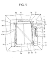
- Figure 1 is a front elevation showing an elevator car door apparatus (sliding door apparatus) according to Embodiment 1 of the present invention from inside a car.
- a car doorway 1a is disposed on a car 1 that can be raised and lowered inside a hoistway.
- the car doorway 1a can be opened and closed by first and second car doors 2a and 2b that function as an elevator door that can be moved horizontally.
- a car doorway frame 3 is disposed around the car doorway 1a.
- the car doorway frame 3 has: first and second vertical frames 3a and 3b that are disposed to the left and right of the car doorway 1a; an upper portion horizontal frame 3c that is disposed between upper end portions of the first and second vertical frames 3a and 3b; and a lower portion horizontal frame 3d that is disposed on a floor portion of the car doorway 1a.
- a car control panel 4 is disposed on a front surface of the second vertical frame 3b.
- a display device 5, an alarm device 6, a plurality of floor designating buttons 7, a door opening button 8, and a door closing button 9 are disposed on the car control panel 4.
- An indicating lamp 10 for displaying the position of the car 1 during motion is disposed on a front surface of the upper portion horizontal frame 3c.
- a first light emitter 11 is disposed on a side surface of the first vertical frame 3a that faces the second vertical frame 3b.
- the first light emitter 11 has a vertically long and continuous first light-emitting surface 11 a.
- a second light emitter 12 is disposed on a side surface of the second vertical frame 3b that faces the first vertical frame 3a.
- the second light emitter 12 has a vertically long and continuous second light-emitting surface 12a.
- the first and second light-emitting surfaces 11a and 12a are disposed over approximately an entire height of the car doorway 1a, and face each other from opposite sides of the car doorway 1 a.
- a first camera 13 that functions as a first imaging means that captures images of the second light-emitting surface 12a is disposed on an upper end portion of the side surface of the first vertical frame 3a that faces the second vertical frame 3b. The first camera 13 is disposed so as to be adjacent to an upper end portion of the first light-emitting surface 11a.
- a second camera 14 that functions as a second imaging means that captures images of the first light-emitting surface 11a is disposed on a lower end portion of the side surface of the second vertical frame 3b that faces the first vertical frame 3a. The second camera 14 is disposed so as to be adjacent to a lower end portion of the second light-emitting surface 12a.
- a first light source 15 that emits a light beam obliquely upward approximately along the first vertical frame 3a is disposed on a lower end portion of the side surface of the first vertical frame 3a that faces the second vertical frame 3b.
- the first light source 15 is disposed so as to be adjacent to a lower end portion of the first light-emitting surface 11a.
- a first photodetector 16 that receives the light beam that has been emitted from the first light source 15 is disposed on a first end portion of a lower surface of the upper portion horizontal frame 3c (an end portion near the first vertical frame 3a).
- a second light source 17 that emits a light beam obliquely upward approximately along the second vertical frame 3b is disposed on a lower end portion of the side surface of the second vertical frame 3b that faces the first vertical frame 3a.
- the second light source 17 is disposed so as to be adjacent to a lower end portion of the second light-emitting surface 12a above the second camera 14.
- a second photodetector 18 that receives the light beam that has been emitted from the second light source 17 is disposed on a second end portion of the lower surface of the upper portion horizontal frame 3c (an end portion near the second vertical frame 3b).
- first and second light sources 15 and 17 at positions approximately 10 to 30 cm from lower ends of the vertical frames 3a and 3b. It is preferable to dispose the first and second photodetectors 16 and 18 at positions on the lower surface of the upper portion horizontal frame 3c approximately 5 to 20 cm from the vertical frames 3a and 3b. Rectilinear detecting regions that are approximately along the vertical frames 3a and 3b can be ensured by adopting such a layout.
- first and second light emitters 11 and 12, the first and second cameras 13 and 14, and the first and second light sources 15 and 17 are preferable to dispose so as to not to project outward from the surfaces of the vertical frames 3a and 3b. It is more preferable to dispose them without recesses or protrusions relative to the surfaces of the vertical frames 3a and 3b in particular. Contact with passengers, carts, etc., that pass through the car doorway 1a can thereby be prevented, and deterioration in detecting precision can also be prevented by preventing accumulation of dust, etc.
- FIG 2 is an outline block diagram that shows a control circuit of the car door apparatus from Figure 1 .
- opening and closing operations of the car doors 2a and 2b are controlled by an opening and closing control portion 19.
- the opening and closing control portion 19 is mounted on the car 1, for example, and controls a door motor (not shown) that drives the car doors 2a and 2b.
- Signals from the first and second cameras 13 and 14 are sent to an image processing and determining portion 20.
- the image processing and determining portion 20 determines whether or not light from the first and second light emitters 11 and 12 is interrupted by an object (an obstruction) during opening and closing of the first and second car doors 2a and 2b based on the signals from the first and second cameras 13 and 14.
- the first and second light emitters 11 and 12, the first and second cameras 13 and 14, the image processing and determining portion 20, the first and second light sources 15 and 17, the alarm device 6, and the opening and closing control portion 19 are controlled by a master control portion 21. Signals from the image processing and determining portion 20, the first and second photodetectors 16 and 18, and the opening and closing control portion 19 are input into the master control portion 21.
- the master control portion 21 shines light from the first and second light emitters 11 and 12 during opening and closing of the car doors 2a and 2b, and monitors for the presence or absence of an object in the vicinity of the car doorway 1a.
- the master control portion 21 also emit light beams from the first and second light sources 15 and 17 at least when the car doors 2a and 2b are open, and monitors for the presence or absence of an object in the vicinity of the first and second vertical frames 3a and 3b.
- the master control portion 21 sends opening and closing commands for the car doors 2a and 2b to the opening and closing control portion 19 depending on an object detection result.
- the opening and closing control portion 19, the image processing and determining portion 20, and the master control portion 21 are each constituted by a microcomputer. However, it is also possible to constitute any two of the opening and closing control portion 19, the image processing and determining portion 20, and the master control portion 21 using a shared microcomputer.
- a controlling apparatus according to Embodiment 1 includes the opening and closing control portion 19 and the master control portion 21.
- a first detecting apparatus 22 that detects objects that are present between the vertical frames 3a and 3b, i.e., in the car doorway 1 a, includes the first and second light emitters 11 and 12, the first and second cameras 13 and 14, and the image processing and determining portion 20.
- a second detecting apparatus 23 that detects objects that are present in a vicinity of the vertical frames 3a and 3b includes the first and second light sources 15 and 17 and the first and second photodetectors 16 and 18.
- a wavelength of light that is used in the first detecting apparatus 22 and a wavelength of light that is used in the second detecting apparatus 23 it is desirable for a wavelength of light that is used in the first detecting apparatus 22 and a wavelength of light that is used in the second detecting apparatus 23 to be different from each other. It is preferable, for example, to make the light emitters 11 and 12 shine red and the cameras 13 and 14 photograph only red in the first detecting apparatus 22, and to make the light sources 15 and 17 emit near-infrared light and the photodetectors 16 and 18 receive only near-infrared light in the second detecting apparatus 23.
- image data ⁇ from the cameras 13 and 14 when the light emitters 11 and 12 are not switched on, and image data ⁇ when the light emitters 11 and 12 are switched on are imported into the image processing and determining portion 20.
- a differential image y is calculated by subtracting the image data ⁇ from the image data ⁇ . An operation of this kind is repeated whenever executing object monitoring.
- light-emitting surface images such as those shown in Figure 4 or Figure 5 will remain in the differential image y since a portion of the light will be interrupted.
- the differential image y in Figure 4 the light-emitting surface image has been divided plurally and is discontinuous.
- the length of the light-emitting surface image in the differential image y in Figure 5 is shorter than normal ( Figure 3 ). If the image processing and determining portion 20 detects that the light-emitting surface image has become discontinuous or has become shorter or that the light-emitting surface image has disappeared, then it determines that an object is present between the vertical frames 3a and 3b and sends a signal to that effect to the master control portion 21.
- the master control portion 21 determines that an object is present in the vicinity of the vertical frames 3a and 3b.
- FIG 6 is a flowchart that shows operation of the master control portion 21 from Figure 2 during door closing.
- the master control portion 21 commences object detecting operations by the first and second detecting apparatuses 22 and 23, and determines the presence or absence of an object (Step S1). If no object is detected at this point, ordinary door opening is commenced at normal timing (Step S2).
- a warning is issued using at least one of the display device 5 or the alarm device 6 in order to move the passengers inside the car 1 away from the car doors 2a and 2b (Step S3).
- a voice or a warning sound
- an announcement such as "Door opening. Please move away from the doors.”, etc., for example, is broadcast by the alarm device 6, or a written message that has been stored in advance is displayed on the display device 5, etc.
- Ordinary door opening is commenced after the object is no longer detected.
- Step S4 object detecting operation by the first detecting apparatus 22 is stopped, and only object detecting operation by the second detecting apparatus 23 (Step S4). If no object is detected by the second detecting apparatus 23, the door opening operation is continued (Step S5). The object detecting operation by the second detecting apparatus 23 is continued until the first and second car doors 2a and 2b move to a position at which door opening is completed (Steps S4 through S6). If the first and second car doors 2a and 2b move to the position at which door opening is completed without an object being detected by the second detecting apparatus 23, the process ends.
- Step S7 if an object is detected by the second detecting apparatus 23 during the door opening operation, the door opening operation is stopped temporarily (Step S7), and a warning operation similar to that above is performed (Step S8).
- the warning operation is continued with the door opening operation stopped until the object is no longer detected by the second detecting apparatus 23.
- the presence or absence of objects is monitored by both a first detecting apparatus 22 that detects objects that are present in a car doorway 1 a, and a second detecting apparatus 23 that detects objects that are positioned in a vicinity of vertical frames 3a and 3b, specifically, in a vicinity of gaps between the vertical frames 3a and 3b and car doors 2a and 2b. Because of this, objects that are positioned in a vicinity of the car doors 2a and 2b can be detected anywhere in the car doorway 1a before commencement of door opening, and objects that are positioned in positions that could obstruct the door opening operation, i.e., in a vicinity of the vertical frames 3a and 3b can be detected after the commencement of door opening.
- the master control portion 21 monitors whether or not an object is detected by at least one of the first and second detecting apparatuses 22 and 23 in an interval from a predetermined amount of time before the commencement of door opening until the commencement of door opening, and monitors whether or not an object is detected only by the second detecting apparatus 23 in an interval from the commencement of door opening until door opening is completed, the presence or absence of objects can be monitored efficiently so as to correspond to the stage of the door opening operation.
- the master control portion 21 issues a warning using the alarm device 6 if an object is detected by at least one of the first and second detecting apparatuses 22 and 23 in an interval from a predetermined amount of time before the commencement of door opening until the commencement of door opening, and issues a warning using the alarm device 6 if an object is detected only by the second detecting apparatus 23 in an interval from the commencement of door opening until door opening is completed, warnings can be issued appropriately so as to correspond to the stage of the door opening operation, enabling the door opening operation to be executed smoothly.
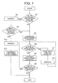
- FIG. 7 is a flowchart that shows operation of a master control portion 21 according to Embodiment 2 of the present invention during door closing, a configuration of a car door apparatus being similar to that of Embodiment 1.
- Step S9 After an object is detected by at least one of the first and second detecting apparatuses 22 and 23 in an interval from a predetermined amount of time before the commencement of door opening until the commencement of door opening, and a warning has been issued using the alarm device 6, reconfirmation is performed as to whether or not an object is detected by at least one of the first and second detecting apparatuses 22 and 23 (Step S9). If the object is no longer being detected, ordinary door opening is commenced (Step S2).
- Step S10 If, on the other hand, the object is detected again despite a warning having been issued, a warning such as "Door opening.”, etc., for example, is issued using the alarm device 6 (Step S10), and the door opening operation is commenced at a lower speed than usual (Step S11).
- Step S11 When low-speed door opening is commenced, the object detecting operations by the first and second detecting apparatuses 22 and 23 are stopped, and low-speed door opening operation is continued until the door opening is completed.
- an elevator car door apparatus of this kind because a door opening operation is performed at a lower speed than usual if an object is detected by at least one of the first and second detecting apparatuses 22 and 23 in an interval from a predetermined amount of time before the commencement of door opening until the commencement of door opening, a state in which door opening does not commence is prevented from being continued indefinitely, enabling convenience to be improved.
- low-speed door opening is commenced if an object is detected again after one warning, but low-speed door opening may also be set so as to commence if the object continues to be detected after a preset number of warnings, door opening not being commenced until then.
- a door opening operation is stopped if an object is detected by the second detecting apparatus 23 after the commencement of door opening, but in that case also the door opening operation may also be set so as to recommence at low speed after one or a plurality of warnings.
- Figure 8 is a cross section of an elevator car door apparatus according to Embodiment 3 of the present invention.
- a first housing 24 is fixed to a first vertical frame 3a so as to face a car doorway 1a.
- a second housing 25 is fixed to a second vertical frame 3b so as to face the car doorway 1 a.
- the first and second housings 24 and 25 are disposed over approximately an entire height of the car doorway 1a, and face each other from opposite sides of the car doorway 1a.
- the first and second housings 24 and 25 are fixed to end portions of the vertical frames 3a and 3b near car doors 2a and 2b.
- Figure 9 is a perspective that shows a first housing from Figure 8
- Figure 10 is a perspective that shows a second housing from Figure 8
- a first light emitter 11, a first camera 13, and a first light source 15 are mounted to the first housing 24
- a second light emitter 12, a second camera 14, and a second light source 17 are mounted to the second housing 25.
- the rest of the configuration is similar to that of Embodiment 1.
- an installation position of the first light source 15 and an installation position of the first photodetector 16 may also be interchanged, and in that case, the first photodetector 16 may also be mounted to the first housing 24.
- an installation position of the second light source 17 and an installation position of the second photodetector 18 may also be interchanged, and the second photodetector 18 may also be mounted to the second housing 25.
- Figure 11 is a perspective that shows a first housing 26 according to Embodiment 4 of the present invention
- Figure 12 is a perspective that shows a second housing 27 according to Embodiment 4.
- the first camera 13 and the first light source 15 were disposed beside the first light emitter 11, and the second camera 14 and the second light source 17 were disposed beside the second light emitter 12.
- a first light emitter 11, a first camera 13, and a first light source 15 are arranged in a single column vertically
- a second light emitter 12, a second camera 14, and a second light source 17 are arranged in a single column vertically.
- the first camera 13 is disposed above the first light emitter 11, the first light source 15 is disposed below the first light emitter 11, the second camera 14 is disposed below the second light emitter 12, and the second light source 17 is disposed below the second camera 14.
- width dimensions of the first and second housings 26 and 27 can be reduced, enabling mounting space for the first and second housings 26 and 27 on the vertical frames 3a and 3b to be reduced.
- the light emitters 11 and 12 were set so as to shine red, and the light sources 15 and 17 to emit near-infrared light, but the light emitters 11 and 12 and the light sources 15 and 17 are not limited to emitting these wavelengths of light.
- the light that the light emitters 11 and 12 emit may also be green, blue, or orange.
- the light emitters 11 and 12 may also be set so as to emit near-infrared light, and the light sources 15 and 17 to emit visible light.
- the light emitters 11 and 12 and the light sources 15 and 17 may also be set so as to emit mutually-different wavelengths of near-infrared light.
- signals from the first and second cameras 13 and 14 are processed by a common image processing and determining portion 20, but may also be processed by two independent image processing and determining portions.
- objects are detected by light being blocked by the object and a light-emitting surface image being interrupted, or becoming shorter, etc., but are not limited to this method for detecting objects.
- a time differential image that is a difference between a newest differential image and a differential image from a predetermined amount of time before may also be found, and a determination made as to whether or not a value that is greater than or equal to a predetermined value is present in the time differential image.
- the time differential image has a value of approximately zero over an entire surface. If a moving object is present, portions that are greater than or equal to the predetermined value appear in the time differential image.
- a sliding door apparatus that opens to two sides has been explained, but the present invention can also be applied to doors that open to one side, and car doors and landing doors are not limited to a particular number of leaves.
- the present invention has been applied to an elevator car door apparatus, but can also be applied to landing door apparatuses.
- a sliding door apparatus according to the present invention can also be applied to a doorway that is disposed in a building, a boarding gate for a passenger vehicle such as a train, etc., or a boarding gate on a train platform.
Abstract
Description
- The present invention relates to a sliding door apparatus that automatically moves a door horizontally, and to an elevator that makes use thereof.
- In conventional sliding door apparatuses, a pair of light emitters that have iong and continuous light-emitting surfaces, and a pair of cameras that capture images of the light-emitting surfaces of facing light emitters are disposed in left and right vertical frames of a doorway, and the entire doorway is thereby covered as a monitored region (see
Patent Literature 1, for example). -
- [Patent Literature 1] Japanese Patent Laid-Open No.
2004-338846 - Conventional sliding door apparatuses such as that described above can detect an object anywhere in a width of the doorway, but cannot determine how far that object is away from the vertical frames. Because of this, if a user attempts to pass through a partially open doorway during a door opening operation, the door opening action may be stopped temporarily on detecting the user even though there is no need for concern that the user might be pulled in between the vertical stanchions and the door, and passage of the user is obstructed unnecessarily.
- The present invention aims to solve the above problems and an object of the present invention is to provide a sliding door apparatus that can improve convenience by detecting an object that is present in the doorway and also determining the position of the detected object, and to provide an elevator that makes use thereof.
- In order to achieve the above object, according to one aspect of the present invention, there is provided a sliding door apparatus including: a door that opens and closes a doorway by being moved horizontally; a first detecting apparatus that has: a light emitter that is disposed on a side portion of the doorway; and an imaging means that faces the light emitter from an opposite side of the doorway and captures images of the light emitter, the first detecting apparatus detecting an object that is present in the doorway; a second detecting apparatus that has: a light source that emits a light beam along a side portion of the doorway; and a photodetector that receives the light beam from the light source, the second detecting apparatus detecting an object that is present in a vicinity of the side portion of the doorway; and a controlling apparatus that controls opening and closing of the door based on information from the first and second detecting apparatuses.
According to another aspect of the present invention, there is provided an elevator including: a car that is raised and lowered inside a hoistway; an elevator door that opens and closes a doorway that is disposed between the car and a landing by being moved horizontally; a first detecting apparatus that has: a light emitter that is disposed on a side portion of the doorway; and an imaging means that faces the light emitter from an opposite side of the doorway and captures images of the light emitter, the first detecting apparatus detecting an object that is present in the doorway; a second detecting apparatus that has: a light source that emits a light beam along a side portion of the doorway; and a photodetector that receives the light beam from the light source, the second detecting apparatus detecting an object that is present in a vicinity of the side portion of the doorway; and a controlling apparatus that controls opening and closing of the elevator door based on information from the first and second detecting apparatuses. -
-
Figure 1 is a front elevation showing an elevator car door apparatus according toEmbodiment 1 of the present invention from inside a car; -
Figure 2 is an outline block diagram that shows a control circuit of the car door apparatus fromFigure 1 ; -
Figure 3 is an explanatory diagram that shows a differential image that is obtained by an image processing and determining portion fromFigure 2 when an object is not present in a monitored region; -
Figure 4 is an explanatory diagram that shows a first example of a differential image that is obtained by the image processing and determining portion fromFigure 2 when an object is present in the monitored region; -
Figure 5 is an explanatory diagram that shows a second example of a differential image that is obtained by the image processing and determining portion fromFigure 2 when an object is present in the monitored region; -
Figure 6 is a flowchart that shows operation of a master control portion fromFigure 2 during door closing; -
Figure 7 is a flowchart that shows operation of a master control portion according toEmbodiment 2 of the present invention during door closing; -
Figure 8 is a cross section of an elevator car door apparatus according toEmbodiment 3 of the present invention; -
Figure 9 is a perspective that shows a first housing fromFigure 8 ; -
Figure 10 is a perspective that shows a second housing fromFigure 8 ; -
Figure 11 is a perspective that shows a first housing according toEmbodiment 4 of the present invention; and -
Figure 12 is a perspective that shows a second housing according toEmbodiment 4. - Preferred embodiments of the present invention will now be explained with reference to the drawings.
-
Figure 1 is a front elevation showing an elevator car door apparatus (sliding door apparatus) according toEmbodiment 1 of the present invention from inside a car. In the figure, acar doorway 1a is disposed on acar 1 that can be raised and lowered inside a hoistway. Thecar doorway 1a can be opened and closed by first andsecond car doors car doorway frame 3 is disposed around thecar doorway 1a. - The
car doorway frame 3 has: first and secondvertical frames car doorway 1a; an upper portionhorizontal frame 3c that is disposed between upper end portions of the first and secondvertical frames horizontal frame 3d that is disposed on a floor portion of thecar doorway 1a. - A
car control panel 4 is disposed on a front surface of the secondvertical frame 3b. Adisplay device 5, analarm device 6, a plurality offloor designating buttons 7, adoor opening button 8, and adoor closing button 9 are disposed on thecar control panel 4. An indicatinglamp 10 for displaying the position of thecar 1 during motion is disposed on a front surface of the upper portionhorizontal frame 3c. - A
first light emitter 11 is disposed on a side surface of the firstvertical frame 3a that faces the secondvertical frame 3b. Thefirst light emitter 11 has a vertically long and continuous first light-emittingsurface 11 a. Asecond light emitter 12 is disposed on a side surface of the secondvertical frame 3b that faces the firstvertical frame 3a. Thesecond light emitter 12 has a vertically long and continuous second light-emittingsurface 12a. The first and second light-emittingsurfaces car doorway 1a, and face each other from opposite sides of thecar doorway 1 a. - A
first camera 13 that functions as a first imaging means that captures images of the second light-emittingsurface 12a is disposed on an upper end portion of the side surface of the firstvertical frame 3a that faces the secondvertical frame 3b. Thefirst camera 13 is disposed so as to be adjacent to an upper end portion of the first light-emittingsurface 11a. Asecond camera 14 that functions as a second imaging means that captures images of the first light-emittingsurface 11a is disposed on a lower end portion of the side surface of the secondvertical frame 3b that faces the firstvertical frame 3a. Thesecond camera 14 is disposed so as to be adjacent to a lower end portion of the second light-emittingsurface 12a. - A
first light source 15 that emits a light beam obliquely upward approximately along the firstvertical frame 3a is disposed on a lower end portion of the side surface of the firstvertical frame 3a that faces the secondvertical frame 3b. Thefirst light source 15 is disposed so as to be adjacent to a lower end portion of the first light-emittingsurface 11a. Afirst photodetector 16 that receives the light beam that has been emitted from thefirst light source 15 is disposed on a first end portion of a lower surface of the upper portionhorizontal frame 3c (an end portion near the firstvertical frame 3a). - A
second light source 17 that emits a light beam obliquely upward approximately along the secondvertical frame 3b is disposed on a lower end portion of the side surface of the secondvertical frame 3b that faces the firstvertical frame 3a. Thesecond light source 17 is disposed so as to be adjacent to a lower end portion of the second light-emittingsurface 12a above thesecond camera 14. Asecond photodetector 18 that receives the light beam that has been emitted from thesecond light source 17 is disposed on a second end portion of the lower surface of the upper portionhorizontal frame 3c (an end portion near the secondvertical frame 3b). - Moreover, it is preferable to dispose the first and
second light sources vertical frames second photodetectors horizontal frame 3c approximately 5 to 20 cm from thevertical frames vertical frames - It is preferable to dispose the first and
second light emitters second cameras second light sources vertical frames vertical frames car doorway 1a can thereby be prevented, and deterioration in detecting precision can also be prevented by preventing accumulation of dust, etc. -
Figure 2 is an outline block diagram that shows a control circuit of the car door apparatus fromFigure 1 . In the figure, opening and closing operations of thecar doors closing control portion 19. The opening andclosing control portion 19 is mounted on thecar 1, for example, and controls a door motor (not shown) that drives thecar doors - Signals from the first and
second cameras portion 20. The image processing and determiningportion 20 determines whether or not light from the first andsecond light emitters second car doors second cameras - The first and second light emitters 11 and 12, the first and
second cameras portion 20, the first andsecond light sources alarm device 6, and the opening andclosing control portion 19 are controlled by amaster control portion 21. Signals from the image processing and determiningportion 20, the first andsecond photodetectors closing control portion 19 are input into themaster control portion 21. - The
master control portion 21 shines light from the first and second light emitters 11 and 12 during opening and closing of thecar doors car doorway 1a. Themaster control portion 21 also emit light beams from the first and secondlight sources car doors vertical frames master control portion 21 sends opening and closing commands for thecar doors closing control portion 19 depending on an object detection result. - The opening and
closing control portion 19, the image processing and determiningportion 20, and themaster control portion 21 are each constituted by a microcomputer. However, it is also possible to constitute any two of the opening andclosing control portion 19, the image processing and determiningportion 20, and themaster control portion 21 using a shared microcomputer. A controlling apparatus according toEmbodiment 1 includes the opening andclosing control portion 19 and themaster control portion 21. - A first detecting
apparatus 22 that detects objects that are present between thevertical frames car doorway 1 a, includes the first and secondlight emitters second cameras portion 20. In addition, a second detectingapparatus 23 that detects objects that are present in a vicinity of thevertical frames light sources second photodetectors - Here, in order to prevent the lights in the first detecting
apparatus 22 and the second detectingapparatus 23 from interfering with each other, it is desirable for a wavelength of light that is used in the first detectingapparatus 22 and a wavelength of light that is used in the second detectingapparatus 23 to be different from each other. It is preferable, for example, to make thelight emitters cameras apparatus 22, and to make thelight sources photodetectors apparatus 23. - Next, a method for detecting objects using the first detecting
apparatus 22 will be explained. First, image data α from thecameras light emitters light emitters portion 20. Then, a differential image y is calculated by subtracting the image data α from the image data β. An operation of this kind is repeated whenever executing object monitoring. - When a differential process of this kind is performed, only an image of the light-emitting
surfaces cameras surfaces Figure 3 will remain in the differential image y. - In contrast to that, if an object that blocks light is present inside the monitored regions, light-emitting surface images such as those shown in
Figure 4 or Figure 5 will remain in the differential image y since a portion of the light will be interrupted. Specifically, in the differential image y inFigure 4 , the light-emitting surface image has been divided plurally and is discontinuous. The length of the light-emitting surface image in the differential image y inFigure 5 is shorter than normal (Figure 3 ). If the image processing and determiningportion 20 detects that the light-emitting surface image has become discontinuous or has become shorter or that the light-emitting surface image has disappeared, then it determines that an object is present between thevertical frames master control portion 21. - Next, a method for detecting objects using the second detecting
apparatus 23 will be explained. When an object is present between thefirst light source 15 and thefirst photodetector 16, the amount of fight from thefirst light source 15 received at thefirst photodetector 16 is reduced. Similarly, when an object is present between the secondlight source 17 and thesecond photodetector 18, the amount of light from the secondlight source 17 received at thesecond photodetector 18 is reduced. Thus, if the amount of light received by the first orsecond photodetector master control portion 21 determines that an object is present in the vicinity of thevertical frames - Next,
Figure 6 is a flowchart that shows operation of themaster control portion 21 fromFigure 2 during door closing. After thecar 1 has stopped at a landing floor, at a predetermined amount of time (several seconds, for example) before thecar doors master control portion 21 commences object detecting operations by the first and second detectingapparatuses - In contrast to that, if an object is detected, a warning is issued using at least one of the
display device 5 or thealarm device 6 in order to move the passengers inside thecar 1 away from thecar doors alarm device 6, or a written message that has been stored in advance is displayed on thedisplay device 5, etc. Ordinary door opening is commenced after the object is no longer detected. - If ordinary door opening is commenced, object detecting operation by the first detecting
apparatus 22 is stopped, and only object detecting operation by the second detecting apparatus 23 (Step S4). If no object is detected by the second detectingapparatus 23, the door opening operation is continued (Step S5). The object detecting operation by the second detectingapparatus 23 is continued until the first andsecond car doors second car doors apparatus 23, the process ends. - On the other hand, if an object is detected by the second detecting
apparatus 23 during the door opening operation, the door opening operation is stopped temporarily (Step S7), and a warning operation similar to that above is performed (Step S8). The warning operation is continued with the door opening operation stopped until the object is no longer detected by the second detectingapparatus 23. - In an elevator car door apparatus of this kind, the presence or absence of objects is monitored by both a first detecting
apparatus 22 that detects objects that are present in acar doorway 1 a, and a second detectingapparatus 23 that detects objects that are positioned in a vicinity ofvertical frames vertical frames car doors car doors car doorway 1a before commencement of door opening, and objects that are positioned in positions that could obstruct the door opening operation, i.e., in a vicinity of thevertical frames open car doorway 1a during the door opening operation, passage of the user can be prevented from being obstructed unnecessarily by enabling the door opening operation to be prevented from being stopped temporarily. In other words, convenience can be improved by detecting an object that is present in thecar doorway 1a and also determining the position of the detected object. - Because the
master control portion 21 monitors whether or not an object is detected by at least one of the first and second detectingapparatuses apparatus 23 in an interval from the commencement of door opening until door opening is completed, the presence or absence of objects can be monitored efficiently so as to correspond to the stage of the door opening operation.
Because themaster control portion 21 issues a warning using thealarm device 6 if an object is detected by at least one of the first and second detectingapparatuses alarm device 6 if an object is detected only by the second detectingapparatus 23 in an interval from the commencement of door opening until door opening is completed, warnings can be issued appropriately so as to correspond to the stage of the door opening operation, enabling the door opening operation to be executed smoothly. -
Figure 7 is a flowchart that shows operation of amaster control portion 21 according toEmbodiment 2 of the present invention during door closing, a configuration of a car door apparatus being similar to that ofEmbodiment 1.
In this example, after an object is detected by at least one of the first and second detectingapparatuses alarm device 6, reconfirmation is performed as to whether or not an object is detected by at least one of the first and second detectingapparatuses 22 and 23 (Step S9). If the object is no longer being detected, ordinary door opening is commenced (Step S2). - If, on the other hand, the object is detected again despite a warning having been issued, a warning such as "Door opening.", etc., for example, is issued using the alarm device 6 (Step S10), and the door opening operation is commenced at a lower speed than usual (Step S11). When low-speed door opening is commenced, the object detecting operations by the first and second detecting
apparatuses - In an elevator car door apparatus of this kind, because a door opening operation is performed at a lower speed than usual if an object is detected by at least one of the first and second detecting
apparatuses - Moreover, in
Embodiment 2, low-speed door opening is commenced if an object is detected again after one warning, but low-speed door opening may also be set so as to commence if the object continues to be detected after a preset number of warnings, door opening not being commenced until then.
InEmbodiment 2, a door opening operation is stopped if an object is detected by the second detectingapparatus 23 after the commencement of door opening, but in that case also the door opening operation may also be set so as to recommence at low speed after one or a plurality of warnings. -
Figure 8 is a cross section of an elevator car door apparatus according toEmbodiment 3 of the present invention. In the figure, afirst housing 24 is fixed to a firstvertical frame 3a so as to face acar doorway 1a. Asecond housing 25 is fixed to a secondvertical frame 3b so as to face thecar doorway 1 a. The first andsecond housings car doorway 1a, and face each other from opposite sides of thecar doorway 1a. The first andsecond housings vertical frames car doors -
Figure 9 is a perspective that shows a first housing fromFigure 8 , andFigure 10 is a perspective that shows a second housing fromFigure 8 . Afirst light emitter 11, afirst camera 13, and afirst light source 15 are mounted to thefirst housing 24. Asecond light emitter 12, asecond camera 14, and a secondlight source 17 are mounted to thesecond housing 25. The rest of the configuration is similar to that ofEmbodiment 1. - In an elevator car door apparatus of this kind, by mounting the
first light emitter 11, thefirst camera 13, and thefirst light source 15 to afirst housing 24 in advance, and mounting thesecond light emitter 12, thesecond camera 14, and the secondlight source 17 to asecond housing 25 in advance, installation work at an installation site can be reduced significantly, enabling workability to be improved. - Moreover, an installation position of the
first light source 15 and an installation position of thefirst photodetector 16 may also be interchanged, and in that case, thefirst photodetector 16 may also be mounted to thefirst housing 24. Similarly, an installation position of the secondlight source 17 and an installation position of thesecond photodetector 18 may also be interchanged, and thesecond photodetector 18 may also be mounted to thesecond housing 25. -
Figure 11 is a perspective that shows afirst housing 26 according toEmbodiment 4 of the present invention, andFigure 12 is a perspective that shows asecond housing 27 according toEmbodiment 4. InEmbodiment 3, thefirst camera 13 and thefirst light source 15 were disposed beside thefirst light emitter 11, and thesecond camera 14 and the secondlight source 17 were disposed beside thesecond light emitter 12. In contrast to that, inEmbodiment 4, afirst light emitter 11, afirst camera 13, and afirst light source 15 are arranged in a single column vertically, and asecond light emitter 12, asecond camera 14, and a secondlight source 17 are arranged in a single column vertically. Specifically, thefirst camera 13 is disposed above thefirst light emitter 11, thefirst light source 15 is disposed below thefirst light emitter 11, thesecond camera 14 is disposed below thesecond light emitter 12, and the secondlight source 17 is disposed below thesecond camera 14. - By adopting a layout of this kind, width dimensions of the first and
second housings second housings vertical frames - Moreover, in the above examples, the
light emitters light sources light emitters light sources light emitters light emitters light sources light emitters light sources - In the above examples, signals from the first and
second cameras portion 20, but may also be processed by two independent image processing and determining portions. - In addition, in the above examples, objects are detected by light being blocked by the object and a light-emitting surface image being interrupted, or becoming shorter, etc., but are not limited to this method for detecting objects. For example, a time differential image that is a difference between a newest differential image and a differential image from a predetermined amount of time before may also be found, and a determination made as to whether or not a value that is greater than or equal to a predetermined value is present in the time differential image. In such methods, if no object is present, the time differential image has a value of approximately zero over an entire surface. If a moving object is present, portions that are greater than or equal to the predetermined value appear in the time differential image. For this reason, it can be determined that an object is present if there is a portion that is greater than or equal to the predetermined value. Using a method of this kind, dust that has adhered to the light-emitting
surface - In the above examples, presence or absence of objects is monitored by both the first and second detecting
apparatuses apparatus 22 in this the time period.
In the above examples, a sliding door apparatus that opens to two sides has been explained, but the present invention can also be applied to doors that open to one side, and car doors and landing doors are not limited to a particular number of leaves.
In addition, in the above examples, the present invention has been applied to an elevator car door apparatus, but can also be applied to landing door apparatuses. For example, a sliding door apparatus according to the present invention can also be applied to a doorway that is disposed in a building, a boarding gate for a passenger vehicle such as a train, etc., or a boarding gate on a train platform.
Claims (7)
- A sliding door apparatus comprising:a door that opens and closes a doorway by being moved horizontally;a first detecting apparatus that has:a light emitter that is disposed on a side portion of the doorway; andan imaging means that faces the light emitter from an oppositeside of the doorway and captures images of the light emitter, the first detecting apparatus detecting an object that is present in the doorway;a second detecting apparatus that has:a light source that emits a light beam along a side portion of the doorway; anda photodetector that receives the light beam from the light source,
the second detecting apparatus detecting an object that is present in a vicinity of the side portion of the doorway; anda controlling apparatus that controls opening and closing of the door based on information from the first and second detecting apparatuses. - A sliding door apparatus according to Claim 1, wherein the control apparatus monitors whether or not an object is detected by at least one of the first and second detecting apparatuses in an interval from a predetermined amount of time before commencement of door opening until commencement of door opening, and monitors whether or not an object is detected only by the second detecting apparatus in an interval from commencement of door opening until completion of door opening.
- A sliding door apparatus according to Claim 2, further comprising an alarm device that issues a warning to a user in a vicinity of the doorway,
wherein the control apparatus issues a warning using the alarm device if an object is detected by at least one of the first and second detecting apparatuses in an interval from a predetermined amount of time before commencement of door opening until commencement of door opening, and issues a warning using the alarm device if an object is detected only by the second detecting apparatus in an interval from commencement of door opening until completion of door opening. - A sliding door apparatus according to Claim 2, wherein the control apparatus performs a door opening operation at a lower speed than usual if an object is detected by at least one of the first and second detecting apparatuses in an interval from a predetermined amount of time before commencement of door opening until commencement of door opening.
- A sliding door apparatus according to Claim 1, wherein:the light emitter includes:a first light emitter that is disposed on a first side of the doorway; anda second light emitter that is disposed on a second side of the doorway;the imaging means includes:a first imaging means that is disposed on a first side of the doorway; anda second imaging means that is disposed on a second side of the doorway;the light source includes:a first light source that is disposed on a first side of the doorway; anda second light source that is disposed on a second side of the doorway;the photodetector includes:a first photodetector that is disposed on a first side of the doorway; anda second photodetector that is disposed on a second side of the doorway;the first light emitter, the first imaging means, and either the first light source or the first photodetector are mounted to a common first housing; andthe second light emitter, the second imaging means, and either the second light source or the second photodetector are mounted to a common second housing.
- A sliding door apparatus according to Claim 1, wherein the light emitter and the light source emit mutually-different wavelengths of light.
- An elevator comprising:a car that is raised and lowered inside a hoistway;an elevator door that opens and closes a doorway that is disposed between the car and a landing by being moved horizontally;a first detecting apparatus that has:the first detecting apparatus detecting an object that is present in the doorway;a light emitter that is disposed on a side portion of the doorway; andan imaging means that faces the light emitter from an opposite side of the doorway and captures images of the light emitter,
a second detecting apparatus that has:a light source that emits a light beam along a side portion of the doorway; anda photodetector that receives the light beam from the light source,a controlling apparatus that controls opening and closing of the elevator door based on information from the first and second detecting apparatuses.
the second detecting apparatus detecting an object that is present in a vicinity of the side portion of the doorway; and
Applications Claiming Priority (1)
| Application Number | Priority Date | Filing Date | Title |
|---|---|---|---|
| PCT/JP2008/062805 WO2010007670A1 (en) | 2008-07-16 | 2008-07-16 | Slide door device and elevator |
Publications (3)
| Publication Number | Publication Date |
|---|---|
| EP2298686A1 true EP2298686A1 (en) | 2011-03-23 |
| EP2298686A4 EP2298686A4 (en) | 2014-01-29 |
| EP2298686B1 EP2298686B1 (en) | 2015-06-24 |
Family
ID=41550089
Family Applications (1)
| Application Number | Title | Priority Date | Filing Date |
|---|---|---|---|
| EP08791200.2A Active EP2298686B1 (en) | 2008-07-16 | 2008-07-16 | Slide door device and elevator |
Country Status (5)
| Country | Link |
|---|---|
| EP (1) | EP2298686B1 (en) |
| JP (1) | JP5554236B2 (en) |
| KR (1) | KR101210182B1 (en) |
| CN (1) | CN102083733B (en) |
| WO (1) | WO2010007670A1 (en) |
Cited By (3)
| Publication number | Priority date | Publication date | Assignee | Title |
|---|---|---|---|---|
| EP2371754A1 (en) * | 2008-12-26 | 2011-10-05 | Mitsubishi Electric Corporation | Slide door device and elevator |
| GB2519929A (en) * | 2013-07-15 | 2015-05-13 | Stannah Lifts Ltd | Improvements in or relating to vertical lifting platforms |
| US11760605B2 (en) | 2018-05-23 | 2023-09-19 | Otis Elevator Company | Elevator door monitoring system, elevator system and elevator door monitoring method |
Families Citing this family (4)
| Publication number | Priority date | Publication date | Assignee | Title |
|---|---|---|---|---|
| JP2011195313A (en) * | 2010-03-23 | 2011-10-06 | Mitsubishi Electric Corp | Door system |
| JP6742543B2 (en) * | 2017-12-28 | 2020-08-19 | 三菱電機株式会社 | Elevator door equipment |
| JP6828108B1 (en) * | 2019-09-09 | 2021-02-10 | 東芝エレベータ株式会社 | Elevator user detection system |
| CN110723614B (en) * | 2019-10-28 | 2021-03-26 | 珠海格力电器股份有限公司 | Protection device for elevator door, elevator and protection method |
Citations (3)
| Publication number | Priority date | Publication date | Assignee | Title |
|---|---|---|---|---|
| JP2004338846A (en) * | 2003-05-14 | 2004-12-02 | Mitsubishi Electric Corp | Slide door device and elevator device |
| EP1518814A1 (en) * | 2002-06-28 | 2005-03-30 | Mitsubishi Denki Kabushiki Kaisha | Door control device of elevator |
| JP3958940B2 (en) * | 2001-03-12 | 2007-08-15 | 三菱電機株式会社 | Door device and elevator device |
Family Cites Families (7)
| Publication number | Priority date | Publication date | Assignee | Title |
|---|---|---|---|---|
| JPH0840677A (en) * | 1994-07-27 | 1996-02-13 | Mitsubishi Denki Bill Techno Service Kk | Safety device of elevator door |
| JP3297394B2 (en) * | 1999-03-29 | 2002-07-02 | 株式会社ツーデン | Mobile door safety device and safety and activation device |
| JP2003040562A (en) * | 2001-07-25 | 2003-02-13 | Mitsubishi Electric Corp | Elevator door safety control device |
| JP3995522B2 (en) * | 2002-05-08 | 2007-10-24 | 三菱電機株式会社 | Elevator equipment |
| DE10260109B4 (en) * | 2002-12-19 | 2014-05-22 | Geze Gmbh | sliding door system |
| JP4481091B2 (en) * | 2004-06-15 | 2010-06-16 | 三菱電機株式会社 | Sliding door device |
| JP4792307B2 (en) * | 2006-03-22 | 2011-10-12 | 株式会社日立製作所 | Elevator door safety control device |
-
2008
- 2008-07-16 KR KR1020107026758A patent/KR101210182B1/en active IP Right Grant
- 2008-07-16 JP JP2010520709A patent/JP5554236B2/en active Active
- 2008-07-16 CN CN200880130186.5A patent/CN102083733B/en active Active
- 2008-07-16 EP EP08791200.2A patent/EP2298686B1/en active Active
- 2008-07-16 WO PCT/JP2008/062805 patent/WO2010007670A1/en active Application Filing
Patent Citations (3)
| Publication number | Priority date | Publication date | Assignee | Title |
|---|---|---|---|---|
| JP3958940B2 (en) * | 2001-03-12 | 2007-08-15 | 三菱電機株式会社 | Door device and elevator device |
| EP1518814A1 (en) * | 2002-06-28 | 2005-03-30 | Mitsubishi Denki Kabushiki Kaisha | Door control device of elevator |
| JP2004338846A (en) * | 2003-05-14 | 2004-12-02 | Mitsubishi Electric Corp | Slide door device and elevator device |
Non-Patent Citations (1)
| Title |
|---|
| See also references of WO2010007670A1 * |
Cited By (5)
| Publication number | Priority date | Publication date | Assignee | Title |
|---|---|---|---|---|
| EP2371754A1 (en) * | 2008-12-26 | 2011-10-05 | Mitsubishi Electric Corporation | Slide door device and elevator |
| EP2371754A4 (en) * | 2008-12-26 | 2014-08-06 | Mitsubishi Electric Corp | Slide door device and elevator |
| GB2519929A (en) * | 2013-07-15 | 2015-05-13 | Stannah Lifts Ltd | Improvements in or relating to vertical lifting platforms |
| GB2519929B (en) * | 2013-07-15 | 2016-09-07 | Stannah Lifts Ltd | Improvements in or relating to vertical lifting platforms |
| US11760605B2 (en) | 2018-05-23 | 2023-09-19 | Otis Elevator Company | Elevator door monitoring system, elevator system and elevator door monitoring method |
Also Published As
| Publication number | Publication date |
|---|---|
| KR20100134797A (en) | 2010-12-23 |
| CN102083733B (en) | 2013-08-28 |
| EP2298686A4 (en) | 2014-01-29 |
| EP2298686B1 (en) | 2015-06-24 |
| JP5554236B2 (en) | 2014-07-23 |
| WO2010007670A1 (en) | 2010-01-21 |
| CN102083733A (en) | 2011-06-01 |
| JPWO2010007670A1 (en) | 2012-01-05 |
| KR101210182B1 (en) | 2012-12-07 |
Similar Documents
| Publication | Publication Date | Title |
|---|---|---|
| EP2298686B1 (en) | Slide door device and elevator | |
| JP5542661B2 (en) | Sliding door device and elevator | |
| KR101051828B1 (en) | Slide door device and elevator | |
| US20090236185A1 (en) | Door device for elevator | |
| EP1518814A1 (en) | Door control device of elevator | |
| JP2008273709A (en) | Elevator device | |
| JP4204896B2 (en) | Sliding door device and elevator device | |
| EP2371754B1 (en) | Slide door device and elevator | |
| CN101578229B (en) | Slide door device and elevator | |
| CN112429609B (en) | User detection system for elevator | |
| KR101724600B1 (en) | Screen door apparatus and method for controlling the same | |
| JP5211935B2 (en) | Sliding door device | |
| JP2008222314A (en) | Crime prevention device for building using elevator | |
| JP2021024727A (en) | Elevator user detection system | |
| JP5020240B2 (en) | Sliding door device and elevator | |
| JP6874104B1 (en) | Elevator system and elevator control method | |
| JP2011098787A (en) | Elevator system |
Legal Events
| Date | Code | Title | Description |
|---|---|---|---|
| PUAI | Public reference made under article 153(3) epc to a published international application that has entered the european phase |
Free format text: ORIGINAL CODE: 0009012 |
|
| 17P | Request for examination filed |
Effective date: 20101108 |
|
| AK | Designated contracting states |
Kind code of ref document: A1 Designated state(s): AT BE BG CH CY CZ DE DK EE ES FI FR GB GR HR HU IE IS IT LI LT LU LV MC MT NL NO PL PT RO SE SI SK TR |
|
| AX | Request for extension of the european patent |
Extension state: AL BA MK RS |
|
| DAX | Request for extension of the european patent (deleted) | ||
| A4 | Supplementary search report drawn up and despatched |
Effective date: 20140108 |
|
| RIC1 | Information provided on ipc code assigned before grant |
Ipc: B66B 13/26 20060101AFI20131220BHEP Ipc: B66B 13/28 20060101ALI20131220BHEP |
|
| GRAP | Despatch of communication of intention to grant a patent |
Free format text: ORIGINAL CODE: EPIDOSNIGR1 |
|
| INTG | Intention to grant announced |
Effective date: 20141216 |
|
| GRAP | Despatch of communication of intention to grant a patent |
Free format text: ORIGINAL CODE: EPIDOSNIGR1 |
|
| INTG | Intention to grant announced |
Effective date: 20150130 |
|
| GRAS | Grant fee paid |
Free format text: ORIGINAL CODE: EPIDOSNIGR3 |
|
| GRAA | (expected) grant |
Free format text: ORIGINAL CODE: 0009210 |
|
| AK | Designated contracting states |
Kind code of ref document: B1 Designated state(s): AT BE BG CH CY CZ DE DK EE ES FI FR GB GR HR HU IE IS IT LI LT LU LV MC MT NL NO PL PT RO SE SI SK TR |
|
| REG | Reference to a national code |
Ref country code: GB Ref legal event code: FG4D |
|
| REG | Reference to a national code |
Ref country code: CH Ref legal event code: EP |
|
| REG | Reference to a national code |
Ref country code: AT Ref legal event code: REF Ref document number: 732789 Country of ref document: AT Kind code of ref document: T Effective date: 20150715 |
|
| REG | Reference to a national code |
Ref country code: IE Ref legal event code: FG4D |
|
| REG | Reference to a national code |
Ref country code: DE Ref legal event code: R096 Ref document number: 602008038705 Country of ref document: DE |
|
| PG25 | Lapsed in a contracting state [announced via postgrant information from national office to epo] |
Ref country code: HR Free format text: LAPSE BECAUSE OF FAILURE TO SUBMIT A TRANSLATION OF THE DESCRIPTION OR TO PAY THE FEE WITHIN THE PRESCRIBED TIME-LIMIT Effective date: 20150624 Ref country code: FI Free format text: LAPSE BECAUSE OF FAILURE TO SUBMIT A TRANSLATION OF THE DESCRIPTION OR TO PAY THE FEE WITHIN THE PRESCRIBED TIME-LIMIT Effective date: 20150624 Ref country code: NO Free format text: LAPSE BECAUSE OF FAILURE TO SUBMIT A TRANSLATION OF THE DESCRIPTION OR TO PAY THE FEE WITHIN THE PRESCRIBED TIME-LIMIT Effective date: 20150924 Ref country code: LT Free format text: LAPSE BECAUSE OF FAILURE TO SUBMIT A TRANSLATION OF THE DESCRIPTION OR TO PAY THE FEE WITHIN THE PRESCRIBED TIME-LIMIT Effective date: 20150624 |
|
| REG | Reference to a national code |
Ref country code: AT Ref legal event code: MK05 Ref document number: 732789 Country of ref document: AT Kind code of ref document: T Effective date: 20150624 |
|
| REG | Reference to a national code |
Ref country code: LT Ref legal event code: MG4D |
|
| PG25 | Lapsed in a contracting state [announced via postgrant information from national office to epo] |
Ref country code: GR Free format text: LAPSE BECAUSE OF FAILURE TO SUBMIT A TRANSLATION OF THE DESCRIPTION OR TO PAY THE FEE WITHIN THE PRESCRIBED TIME-LIMIT Effective date: 20150925 Ref country code: LV Free format text: LAPSE BECAUSE OF FAILURE TO SUBMIT A TRANSLATION OF THE DESCRIPTION OR TO PAY THE FEE WITHIN THE PRESCRIBED TIME-LIMIT Effective date: 20150624 Ref country code: BG Free format text: LAPSE BECAUSE OF FAILURE TO SUBMIT A TRANSLATION OF THE DESCRIPTION OR TO PAY THE FEE WITHIN THE PRESCRIBED TIME-LIMIT Effective date: 20150924 |
|
| REG | Reference to a national code |
Ref country code: NL Ref legal event code: MP Effective date: 20150624 |
|
| PG25 | Lapsed in a contracting state [announced via postgrant information from national office to epo] |
Ref country code: EE Free format text: LAPSE BECAUSE OF FAILURE TO SUBMIT A TRANSLATION OF THE DESCRIPTION OR TO PAY THE FEE WITHIN THE PRESCRIBED TIME-LIMIT Effective date: 20150624 |
|
| PG25 | Lapsed in a contracting state [announced via postgrant information from national office to epo] |
Ref country code: RO Free format text: LAPSE BECAUSE OF NON-PAYMENT OF DUE FEES Effective date: 20150624 Ref country code: SK Free format text: LAPSE BECAUSE OF FAILURE TO SUBMIT A TRANSLATION OF THE DESCRIPTION OR TO PAY THE FEE WITHIN THE PRESCRIBED TIME-LIMIT Effective date: 20150624 Ref country code: PL Free format text: LAPSE BECAUSE OF FAILURE TO SUBMIT A TRANSLATION OF THE DESCRIPTION OR TO PAY THE FEE WITHIN THE PRESCRIBED TIME-LIMIT Effective date: 20150624 Ref country code: CZ Free format text: LAPSE BECAUSE OF FAILURE TO SUBMIT A TRANSLATION OF THE DESCRIPTION OR TO PAY THE FEE WITHIN THE PRESCRIBED TIME-LIMIT Effective date: 20150624 Ref country code: ES Free format text: LAPSE BECAUSE OF FAILURE TO SUBMIT A TRANSLATION OF THE DESCRIPTION OR TO PAY THE FEE WITHIN THE PRESCRIBED TIME-LIMIT Effective date: 20150624 Ref country code: AT Free format text: LAPSE BECAUSE OF FAILURE TO SUBMIT A TRANSLATION OF THE DESCRIPTION OR TO PAY THE FEE WITHIN THE PRESCRIBED TIME-LIMIT Effective date: 20150624 Ref country code: IS Free format text: LAPSE BECAUSE OF FAILURE TO SUBMIT A TRANSLATION OF THE DESCRIPTION OR TO PAY THE FEE WITHIN THE PRESCRIBED TIME-LIMIT Effective date: 20151024 Ref country code: PT Free format text: LAPSE BECAUSE OF FAILURE TO SUBMIT A TRANSLATION OF THE DESCRIPTION OR TO PAY THE FEE WITHIN THE PRESCRIBED TIME-LIMIT Effective date: 20151026 |
|
| REG | Reference to a national code |
Ref country code: CH Ref legal event code: PL |
|
| REG | Reference to a national code |
Ref country code: DE Ref legal event code: R097 Ref document number: 602008038705 Country of ref document: DE |
|
| PG25 | Lapsed in a contracting state [announced via postgrant information from national office to epo] |
Ref country code: MC Free format text: LAPSE BECAUSE OF FAILURE TO SUBMIT A TRANSLATION OF THE DESCRIPTION OR TO PAY THE FEE WITHIN THE PRESCRIBED TIME-LIMIT Effective date: 20150624 |
|
| REG | Reference to a national code |
Ref country code: IE Ref legal event code: MM4A |
|
| PG25 | Lapsed in a contracting state [announced via postgrant information from national office to epo] |
Ref country code: CH Free format text: LAPSE BECAUSE OF NON-PAYMENT OF DUE FEES Effective date: 20150731 Ref country code: DK Free format text: LAPSE BECAUSE OF FAILURE TO SUBMIT A TRANSLATION OF THE DESCRIPTION OR TO PAY THE FEE WITHIN THE PRESCRIBED TIME-LIMIT Effective date: 20150624 Ref country code: LI Free format text: LAPSE BECAUSE OF NON-PAYMENT OF DUE FEES Effective date: 20150731 Ref country code: IT Free format text: LAPSE BECAUSE OF FAILURE TO SUBMIT A TRANSLATION OF THE DESCRIPTION OR TO PAY THE FEE WITHIN THE PRESCRIBED TIME-LIMIT Effective date: 20150624 |
|
| PLBE | No opposition filed within time limit |
Free format text: ORIGINAL CODE: 0009261 |
|
| REG | Reference to a national code |
Ref country code: FR Ref legal event code: ST Effective date: 20160331 |
|
| STAA | Information on the status of an ep patent application or granted ep patent |
Free format text: STATUS: NO OPPOSITION FILED WITHIN TIME LIMIT |
|
| GBPC | Gb: european patent ceased through non-payment of renewal fee |
Effective date: 20150924 |
|
| PG25 | Lapsed in a contracting state [announced via postgrant information from national office to epo] |
Ref country code: FR Free format text: LAPSE BECAUSE OF NON-PAYMENT OF DUE FEES Effective date: 20150824 |
|
| 26N | No opposition filed |
Effective date: 20160329 |
|
| PG25 | Lapsed in a contracting state [announced via postgrant information from national office to epo] |
Ref country code: IE Free format text: LAPSE BECAUSE OF NON-PAYMENT OF DUE FEES Effective date: 20150716 Ref country code: GB Free format text: LAPSE BECAUSE OF NON-PAYMENT OF DUE FEES Effective date: 20150924 |
|
| PG25 | Lapsed in a contracting state [announced via postgrant information from national office to epo] |
Ref country code: SI Free format text: LAPSE BECAUSE OF FAILURE TO SUBMIT A TRANSLATION OF THE DESCRIPTION OR TO PAY THE FEE WITHIN THE PRESCRIBED TIME-LIMIT Effective date: 20150624 |
|
| PG25 | Lapsed in a contracting state [announced via postgrant information from national office to epo] |
Ref country code: BE Free format text: LAPSE BECAUSE OF FAILURE TO SUBMIT A TRANSLATION OF THE DESCRIPTION OR TO PAY THE FEE WITHIN THE PRESCRIBED TIME-LIMIT Effective date: 20150624 |
|
| PG25 | Lapsed in a contracting state [announced via postgrant information from national office to epo] |
Ref country code: MT Free format text: LAPSE BECAUSE OF FAILURE TO SUBMIT A TRANSLATION OF THE DESCRIPTION OR TO PAY THE FEE WITHIN THE PRESCRIBED TIME-LIMIT Effective date: 20150624 |
|
| PG25 | Lapsed in a contracting state [announced via postgrant information from national office to epo] |
Ref country code: HU Free format text: LAPSE BECAUSE OF FAILURE TO SUBMIT A TRANSLATION OF THE DESCRIPTION OR TO PAY THE FEE WITHIN THE PRESCRIBED TIME-LIMIT; INVALID AB INITIO Effective date: 20080716 |
|
| PG25 | Lapsed in a contracting state [announced via postgrant information from national office to epo] |
Ref country code: CY Free format text: LAPSE BECAUSE OF FAILURE TO SUBMIT A TRANSLATION OF THE DESCRIPTION OR TO PAY THE FEE WITHIN THE PRESCRIBED TIME-LIMIT Effective date: 20150624 Ref country code: SE Free format text: LAPSE BECAUSE OF FAILURE TO SUBMIT A TRANSLATION OF THE DESCRIPTION OR TO PAY THE FEE WITHIN THE PRESCRIBED TIME-LIMIT Effective date: 20150624 Ref country code: NL Free format text: LAPSE BECAUSE OF FAILURE TO SUBMIT A TRANSLATION OF THE DESCRIPTION OR TO PAY THE FEE WITHIN THE PRESCRIBED TIME-LIMIT Effective date: 20150624 |
|
| PG25 | Lapsed in a contracting state [announced via postgrant information from national office to epo] |
Ref country code: TR Free format text: LAPSE BECAUSE OF FAILURE TO SUBMIT A TRANSLATION OF THE DESCRIPTION OR TO PAY THE FEE WITHIN THE PRESCRIBED TIME-LIMIT Effective date: 20150624 |
|
| PG25 | Lapsed in a contracting state [announced via postgrant information from national office to epo] |
Ref country code: LU Free format text: LAPSE BECAUSE OF NON-PAYMENT OF DUE FEES Effective date: 20150716 |
|
| REG | Reference to a national code |
Ref country code: DE Ref legal event code: R084 Ref document number: 602008038705 Country of ref document: DE |
|
| P01 | Opt-out of the competence of the unified patent court (upc) registered |
Effective date: 20230512 |
|
| PGFP | Annual fee paid to national office [announced via postgrant information from national office to epo] |
Ref country code: DE Payment date: 20230531 Year of fee payment: 16 |