EP2298225B1 - Arrangement for using a template to form holes for implants in jaw bone - Google Patents
Arrangement for using a template to form holes for implants in jaw bone Download PDFInfo
- Publication number
- EP2298225B1 EP2298225B1 EP10009891.2A EP10009891A EP2298225B1 EP 2298225 B1 EP2298225 B1 EP 2298225B1 EP 10009891 A EP10009891 A EP 10009891A EP 2298225 B1 EP2298225 B1 EP 2298225B1
- Authority
- EP
- European Patent Office
- Prior art keywords
- template
- jaw bone
- gum
- bone
- anchoring elements
- Prior art date
- Legal status (The legal status is an assumption and is not a legal conclusion. Google has not performed a legal analysis and makes no representation as to the accuracy of the status listed.)
- Expired - Lifetime
Links
- 239000007943 implant Substances 0.000 title claims abstract description 23
- 238000004873 anchoring Methods 0.000 claims abstract description 25
- 210000000988 bone and bone Anatomy 0.000 claims abstract description 24
- 238000002513 implantation Methods 0.000 claims description 15
- 210000005036 nerve Anatomy 0.000 claims description 10
- 238000013461 design Methods 0.000 claims description 6
- 238000000034 method Methods 0.000 claims description 4
- 238000004088 simulation Methods 0.000 claims description 3
- 230000015572 biosynthetic process Effects 0.000 abstract description 7
- 230000000694 effects Effects 0.000 abstract description 2
- 238000011477 surgical intervention Methods 0.000 abstract description 2
- 230000006870 function Effects 0.000 description 15
- 230000001419 dependent effect Effects 0.000 description 2
- 210000004195 gingiva Anatomy 0.000 description 2
- 238000003780 insertion Methods 0.000 description 2
- 230000037431 insertion Effects 0.000 description 2
- 230000003993 interaction Effects 0.000 description 2
- 238000002591 computed tomography Methods 0.000 description 1
- 238000011161 development Methods 0.000 description 1
- 230000018109 developmental process Effects 0.000 description 1
- 238000010586 diagram Methods 0.000 description 1
- 238000005516 engineering process Methods 0.000 description 1
- 230000035876 healing Effects 0.000 description 1
- 230000002452 interceptive effect Effects 0.000 description 1
- 230000003340 mental effect Effects 0.000 description 1
- 238000012546 transfer Methods 0.000 description 1
- 230000000007 visual effect Effects 0.000 description 1
Images

Classifications
-
- A—HUMAN NECESSITIES
- A61—MEDICAL OR VETERINARY SCIENCE; HYGIENE
- A61B—DIAGNOSIS; SURGERY; IDENTIFICATION
- A61B17/00—Surgical instruments, devices or methods, e.g. tourniquets
- A61B17/16—Bone cutting, breaking or removal means other than saws, e.g. Osteoclasts; Drills or chisels for bones; Trepans
- A61B17/17—Guides or aligning means for drills, mills, pins or wires
- A61B17/1739—Guides or aligning means for drills, mills, pins or wires specially adapted for particular parts of the body
- A61B17/176—Guides or aligning means for drills, mills, pins or wires specially adapted for particular parts of the body for the jaw
-
- A—HUMAN NECESSITIES
- A61—MEDICAL OR VETERINARY SCIENCE; HYGIENE
- A61C—DENTISTRY; APPARATUS OR METHODS FOR ORAL OR DENTAL HYGIENE
- A61C1/00—Dental machines for boring or cutting ; General features of dental machines or apparatus, e.g. hand-piece design
- A61C1/08—Machine parts specially adapted for dentistry
- A61C1/082—Positioning or guiding, e.g. of drills
- A61C1/084—Positioning or guiding, e.g. of drills of implanting tools
-
- A—HUMAN NECESSITIES
- A61—MEDICAL OR VETERINARY SCIENCE; HYGIENE
- A61B—DIAGNOSIS; SURGERY; IDENTIFICATION
- A61B34/00—Computer-aided surgery; Manipulators or robots specially adapted for use in surgery
- A61B34/10—Computer-aided planning, simulation or modelling of surgical operations
Definitions
- the present invention relates, inter alia, to an arrangement for using a template to form holes for implants in bone, preferably jaw bone, without any negative effect from the existing resiliency in the flesh surrounding the bone, for example the gum (gingiva).
- the template in question is adapted to the shape or shapes of the bone and of the gum and has guide holes for a hole-forming unit which can consist of drill equipment known per se.
- a device in accordance with the above in which a holed template is arranged to be applied to an implantation site.
- the device in this case comprises one or more first apparatus arranged to scan the implantation site and initiate electronic, preferably digital, signals concerning the implantation site and send them to a computer appliance.
- the latter is arranged to simulate the implantation site and the holed template which is adapted to the latter.
- the computer appliance is arranged to supply information on all or part of the simulated situation and is arranged to forward or transmit the information to second apparatus designed or cooperating with production equipment for or of the simulated holed template.
- the template is arranged to form holes for implants for anchoring a dental bridge with several implant attachments.
- the anchoring elements have long and narrow or needle-shaped designs arranged to extend through side holes or side recesses in the side walls of the template.
- the anchoring elements for dental bridges are at least three in number, two of the anchoring elements being arranged on or at a distance from the ends of the bridge and one or more anchoring elements being arranged at the central parts of the dental bridge.
- Each anchoring element is arranged to extend substantially horizontally through the gum and the jaw bone. Alternatively, or in addition to this, the anchoring elements can extend only partially into the gum.
- the computer appliance initially mentioned is arranged to indicate a holed template shape for application to the bone, with the gum lying in between.
- the computer appliance is further arranged, with the aid of the information obtained from the first apparatus and/or user information sent to the computer equipment (in so-called interactive mode between the user and the computer appliance) and/or empirical information which can be gathered from a library, fact-containing member, etc., to execute a determination function so as to determine nerve-rich areas of the bone (jaw bone).
- the computer appliance in connection with the information sent to the second apparatus, is arranged to provide, in addition to data on the holed template shape, also data concerning positions and extents for securing elements which are intended to extend through the gum and into and preferably through the whole bone (jaw bone), with account being taken of the routes of said nerve paths.
- an implant site in the form of or on a jaw bone is indicated diagrammatically by 1.
- the jaw bone is shown in a vertical view 1a, and in a horizontal view 1b.
- the implant site or the jaw bone is to be provided with a dental bridge, and in the present case all the teeth in the jaw bone in question are to be replaced by a dental bridge.
- the implant site can be scanned with a scanning function, which can be an X-ray function, for example computed tomography.
- the scanning of the implant site can be done in an alternative way with a scanner (which can be known per se), a camera, etc.
- the scanning function in question is indicated diagrammatically by 2, and the scanning function or the scanning equipment is arranged to generate scanning-dependent signals i1 in a manner known per se.
- the equipment comprises an apparatus 3 receiving said signals i1.
- This apparatus 3 is arranged to generate signals i1', as a function of said signals i1, and send them to a computer-based appliance which is symbolized by 4.
- the computer appliance can be of a type known per se and can for example have the form of a PC.
- the term computer appliance must be seen here in its widest sense, in which the computer appliance has a screen 4a and 4b and is arranged with memory elements and software which can be of a known type.
- the computer appliance can operate with software known per se which is added to or is arranged in a memory or memory devices 5, for example said memory elements.
- the computer appliance can also include or can be connected to further information which can be used in connection with template production, for example appliances in the form of library functions and/or empirical functions. Said connection function is indicated by 6 in Figure 1 .
- the computer appliance is arranged to be able to simulate, preferably visually, the present implant situation as a function of said software known per se.
- the appliance is also arranged to use the known software so as to generate a template design which can be used for the implant situation in question.
- the generating takes place in interaction with a user 7 who, in said interaction, uses a visual computer screen 4a and a keyboard 4b, voice control, etc.
- the simulation of the implant site and the suitable template produced for hole formation are transmitted in the form of digital signals i2 to a production site 8 for production of the model.
- the production site 8 can be arranged locally or at a remote point, and the information transfer can be done via the telecommunications and/or computer network which has been indicated by 9.
- the production site 8 thus produces a template 10 which corresponds to the template simulated in the computer appliance.
- the template is provided with recesses or holes 12 guiding the hole-forming arrangement (drill) 11, with positions which correspond to the planned positions for the implants in the jaw bone.
- the template 10 is intended to be arranged on a jaw bone or equivalent 13 which is covered by gum 14. In accordance with the concept of the invention, the template is to be applied to the jaw bone 13 with the gum 14 lying in between.
- Said information i2 thus contains information concerning the template design.
- the information i2 contains data on the positions and extents for securing elements which are intended to extend through the gum and into and preferably through the whole bone (jaw bone).
- said information i2 contains data on the routes of nerve paths in connection with the bone/jaw bone.
- the template 10 is applied on the gum and the jaw bone.
- Information on applications of the implants from the computer appliance 4 have resulted in drill hole positions having been established on the template 10.
- drill holes 15, 16, 17, 18 and 19 have been established.
- the application of said securing elements is arranged as a function of said hole and implant positions.
- outer securing elements 20, 21 are arranged to extend through the gum and the jaw bone at the ends 10a and 10b of the dental bridge and/or between the outermost and next to outermost fixtures in the dental bridge.
- the alternative or supplementary positions are indicated by broken lines 20a and 21a, respectively.
- Further securing elements 22, 23 extend through the gum and the bone at central parts 10c of the dental bridge.
- the routes for the securing elements are arranged as a function of or to avoid the nerve paths which have been symbolized by 24, 25 in Figure 2 .
- the securing elements preferably extend through the jaw bone in its main horizontal direction.
- the securing elements are indicated diagrammatically in Figure 2 and have a long and narrow or needle-shaped design.
- the purpose of the securing elements is that they are to be firmly anchored to the bone/jaw bone and that the resiliency of the gum lying in between must not affect the position of the template when the template has been anchored to the bone/jaw bone by means of the anchoring elements.
- the formation of the holes in the bone/jaw bone means that the gum must be penetrated by the hole-forming equipment (see 11 in Figure 1 ).
- the number of securing elements can vary from case to case. In a preferred illustrative embodiment which applies for example to dental bridges, at least three securing elements are used, two of the securing elements being arranged at said bridge ends and/or between the outermost and next to outermost fixtures in the dental bridge.
- the alternative or supplementary positions are indicated by broken lines 20a and 21a respectively, and one or more securing elements are arranged at the central parts.
- the template is indicated by 10 and the bone or jaw bone by 13, and the gum lying in between is indicated by 14.
- the template is provided with side recesses, two side recesses toward the front being shown by 26 and 27 in Figure 3 .
- each securing element 32 can be inserted into a hole or a hole formation 33 which extends completely or partly through the template and the jaw bone preferably in the horizontal direction.
- the elements have members 32a in the form of a head which determine the position of insertion.
- each jaw bone 28, 34 has underlying bone, and, in accordance with the invention, gum 28a located on the latter in the embodiment according to Figures 4 and 5 does not have to be opened.
Landscapes
- Health & Medical Sciences (AREA)
- Oral & Maxillofacial Surgery (AREA)
- Life Sciences & Earth Sciences (AREA)
- Dentistry (AREA)
- Veterinary Medicine (AREA)
- Surgery (AREA)
- Public Health (AREA)
- General Health & Medical Sciences (AREA)
- Animal Behavior & Ethology (AREA)
- Heart & Thoracic Surgery (AREA)
- Medical Informatics (AREA)
- Molecular Biology (AREA)
- Biomedical Technology (AREA)
- Engineering & Computer Science (AREA)
- Nuclear Medicine, Radiotherapy & Molecular Imaging (AREA)
- Orthopedic Medicine & Surgery (AREA)
- Epidemiology (AREA)
- Dental Prosthetics (AREA)
- Dental Tools And Instruments Or Auxiliary Dental Instruments (AREA)
- Surgical Instruments (AREA)
- Prostheses (AREA)
Abstract
Description
- Arrangement and device for forming holes for implants in jaw bone.
- The present invention relates, inter alia, to an arrangement for using a template to form holes for implants in bone, preferably jaw bone, without any negative effect from the existing resiliency in the flesh surrounding the bone, for example the gum (gingiva). The template in question is adapted to the shape or shapes of the bone and of the gum and has guide holes for a hole-forming unit which can consist of drill equipment known per se. Also disclosed is a device in accordance with the above in which a holed template is arranged to be applied to an implantation site. The device in this case comprises one or more first apparatus arranged to scan the implantation site and initiate electronic, preferably digital, signals concerning the implantation site and send them to a computer appliance. The latter is arranged to simulate the implantation site and the holed template which is adapted to the latter. The computer appliance is arranged to supply information on all or part of the simulated situation and is arranged to forward or transmit the information to second apparatus designed or cooperating with production equipment for or of the simulated holed template.
- It has long been known to use templates to form holes in the jaw bone, for example as shown in
US5989025 . It is also known that it can be difficult to obtain the necessarily exact hole formation unless the gum, i.e. the gingiva, is folded back and the jaw bone thereby exposed, because the gum or similar is a soft elastic mass with resilient properties which can interfere with the template application and the hole formation. - There is a great disadvantage in carrying out surgical interventions for exposing the jaw bone, i.e. by folding back the gum. This causes inconveniences for the patient, and the implantation work is also painful because the hole formation and the implant insertion have to be followed by a process of healing, which can last some considerable time. There are now specific needs to substantially shorten the time required for the implantation work. It is also expedient to use modern technology with computer-based scanning and production for the templates in question. The main object of the present invention is to solve this problem.
- The features which characterize the invention are defined in claim 1 as appended. The template is arranged to form holes for implants for anchoring a dental bridge with several implant attachments. The anchoring elements have long and narrow or needle-shaped designs arranged to extend through side holes or side recesses in the side walls of the template. The anchoring elements for dental bridges are at least three in number, two of the anchoring elements being arranged on or at a distance from the ends of the bridge and one or more anchoring elements being arranged at the central parts of the dental bridge. Each anchoring element is arranged to extend substantially horizontally through the gum and the jaw bone. Alternatively, or in addition to this, the anchoring elements can extend only partially into the gum. The computer appliance initially mentioned is arranged to indicate a holed template shape for application to the bone, with the gum lying in between. The computer appliance is further arranged, with the aid of the information obtained from the first apparatus and/or user information sent to the computer equipment (in so-called interactive mode between the user and the computer appliance) and/or empirical information which can be gathered from a library, fact-containing member, etc., to execute a determination function so as to determine nerve-rich areas of the bone (jaw bone). Further characteristics are that, in connection with the information sent to the second apparatus, the computer appliance is arranged to provide, in addition to data on the holed template shape, also data concerning positions and extents for securing elements which are intended to extend through the gum and into and preferably through the whole bone (jaw bone), with account being taken of the routes of said nerve paths.
- Further developments of the device according to the invention are set out in the attached dependent claims concerning the device.
- A presently proposed embodiment of an arrangement and a device according to the invention will be described below with reference to the attached drawing, in which
- Figure 1
- shows, in block diagram form, a computer-based function for production of a holed template in connection with a patient, in which a scanning function is included and the scanning function is connected to a computer-based apparatus which in turn is arranged to deliver information to production equipment for the template in question,
- Figure 2
- shows, in horizontal view, a template applied to a jaw bone with the gum lying in between, and where securing elements for securing the template to a jaw bone are indicated,
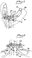
- Figure 3
- shows template, gum and jaw bone in a vertical view,
- Figure 4
- shows in perspective, obliquely from above right and from in front, the application of a template to a lower jaw bone,
- Figure 5
- shows a rear view of the template and the jaw bone according to
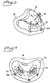
Figure 4 , - Figure 6
- shows, in perspective, the application of the template to an upper jaw, and
- Figure 7
- shows the template application according to
Figure 6 from above. - In
Figure 1 , an implant site in the form of or on a jaw bone is indicated diagrammatically by 1. The jaw bone is shown in a vertical view 1a, and in ahorizontal view 1b. The implant site or the jaw bone is to be provided with a dental bridge, and in the present case all the teeth in the jaw bone in question are to be replaced by a dental bridge. The implant site can be scanned with a scanning function, which can be an X-ray function, for example computed tomography. Alternatively, the scanning of the implant site can be done in an alternative way with a scanner (which can be known per se), a camera, etc. The scanning function in question is indicated diagrammatically by 2, and the scanning function or the scanning equipment is arranged to generate scanning-dependent signals i1 in a manner known per se. The equipment comprises anapparatus 3 receiving said signals i1. Thisapparatus 3 is arranged to generate signals i1', as a function of said signals i1, and send them to a computer-based appliance which is symbolized by 4. The computer appliance can be of a type known per se and can for example have the form of a PC. The term computer appliance must be seen here in its widest sense, in which the computer appliance has a screen 4a and 4b and is arranged with memory elements and software which can be of a known type. The computer appliance can operate with software known per se which is added to or is arranged in a memory ormemory devices 5, for example said memory elements. The computer appliance can also include or can be connected to further information which can be used in connection with template production, for example appliances in the form of library functions and/or empirical functions. Said connection function is indicated by 6 inFigure 1 . - The computer appliance is arranged to be able to simulate, preferably visually, the present implant situation as a function of said software known per se. The appliance is also arranged to use the known software so as to generate a template design which can be used for the implant situation in question. The generating takes place in interaction with a user 7 who, in said interaction, uses a visual computer screen 4a and a keyboard 4b, voice control, etc.
- The simulation of the implant site and the suitable template produced for hole formation are transmitted in the form of digital signals i2 to a
production site 8 for production of the model. Theproduction site 8 can be arranged locally or at a remote point, and the information transfer can be done via the telecommunications and/or computer network which has been indicated by 9. Theproduction site 8 thus produces atemplate 10 which corresponds to the template simulated in the computer appliance. The template is provided with recesses orholes 12 guiding the hole-forming arrangement (drill) 11, with positions which correspond to the planned positions for the implants in the jaw bone. Thetemplate 10 is intended to be arranged on a jaw bone or equivalent 13 which is covered bygum 14. In accordance with the concept of the invention, the template is to be applied to thejaw bone 13 with thegum 14 lying in between. - Said information i2 thus contains information concerning the template design. In addition, the information i2 contains data on the positions and extents for securing elements which are intended to extend through the gum and into and preferably through the whole bone (jaw bone). In addition, said information i2 contains data on the routes of nerve paths in connection with the bone/jaw bone.
- In
Figure 2 , thetemplate 10 is applied on the gum and the jaw bone. Information on applications of the implants from the computer appliance 4 (seeFigure 1 ) have resulted in drill hole positions having been established on thetemplate 10. In the illustrative embodiment according toFigure 2 , drill holes 15, 16, 17, 18 and 19 have been established. The application of said securing elements is arranged as a function of said hole and implant positions. In atemplate 10 for a given dental bridge, outer securingelements ends 10a and 10b of the dental bridge and/or between the outermost and next to outermost fixtures in the dental bridge. The alternative or supplementary positions are indicated bybroken lines 20a and 21a, respectively. Further securingelements central parts 10c of the dental bridge. In accordance with the planning effected with the aid of the computer appliance 4 (seeFigure 1 ), the routes for the securing elements are arranged as a function of or to avoid the nerve paths which have been symbolized by 24, 25 inFigure 2 . The securing elements preferably extend through the jaw bone in its main horizontal direction. The securing elements are indicated diagrammatically inFigure 2 and have a long and narrow or needle-shaped design. The purpose of the securing elements is that they are to be firmly anchored to the bone/jaw bone and that the resiliency of the gum lying in between must not affect the position of the template when the template has been anchored to the bone/jaw bone by means of the anchoring elements. The formation of the holes in the bone/jaw bone means that the gum must be penetrated by the hole-forming equipment (see 11 inFigure 1 ). The number of securing elements can vary from case to case. In a preferred illustrative embodiment which applies for example to dental bridges, at least three securing elements are used, two of the securing elements being arranged at said bridge ends and/or between the outermost and next to outermost fixtures in the dental bridge. The alternative or supplementary positions are indicated bybroken lines 20a and 21a respectively, and one or more securing elements are arranged at the central parts. - In
Figure 3 , the template is indicated by 10 and the bone or jaw bone by 13, and the gum lying in between is indicated by 14. The template is provided with side recesses, two side recesses toward the front being shown by 26 and 27 inFigure 3 . - In
Figures 4 and 5 , a lower jaw is indicated by 28, and the main nerve path of the lower jaw (mental foramen) is indicated by 29. The surgical template is shown by 30 and its guide sleeves by 31. In accordance with the above, each securingelement 32 can be inserted into a hole or a hole formation 33 which extends completely or partly through the template and the jaw bone preferably in the horizontal direction. The elements have members 32a in the form of a head which determine the position of insertion. - In
Figures 6 and 7 , theupper jaw 34 is shown from below with the appliedtemplate 35 and itsguide members 36 for securingelements 37 which are provided with ahead 37a. As is known, eachjaw bone gum 28a located on the latter in the embodiment according toFigures 4 and 5 does not have to be opened. As regards the structure of the bone and of the gum, reference is made to the known literature.
Claims (12)
- An arrangement for forming holes for implants in a jaw bone (28, 34), the arrangement comprising
a template (30, 35) being adapted to the shape(s) of the jaw bone and of the gum, the template having two or more side holes or recesses (26, 27) through which anchoring elements in use are arranged to extend, and the template having guide holes for a hole-forming unit, wherein the template is designed for application to the jaw bone with the gum lying in between, and
two or more anchoring elements (32, 37) cooperating with the template, the two or more anchoring elements being intended to extend through the gum and into the jaw bone, wherein the routes for the anchoring elements (32, 37) are arranged as a function of or to avoid nerve paths in the jaw bone when the template (30, 35) and anchoring elements are used. - The arrangement as claimed in patent claim 1, wherein guide holes of the template (30, 35) have positions which correspond to the planned positions for implants for anchoring a dental bridge with several securing points or implant attachments in the jaw bone.
- The arrangement as claimed in patent claim 1 or 2, wherein the anchoring elements are long and narrow or needle-shaped and preferably provided with heads and are arranged to extend through side holes or side recesses (26, 27) in the side walls of the template.
- The arrangement as claimed in patent claim 1 or 2, wherein the anchoring elements are at least three in number, and in that two of the anchoring elements (32, 37) are arranged between the outermost and second outermost guide holes of the template (30, 35), and in that one or more anchoring elements (32, 37) are arranged at central parts of the template (30, 35).
- The arrangement as claimed in any of the preceding patent claims, wherein one or more of the anchoring elements (32, 37) are arranged to in use extend substantially horizontally relative to the template (30, 35).
- The arrangement as claimed in any of the preceding patent claims, wherein one or more first anchoring elements are intended to extend through the gum and the jaw bone, and in that one or more second anchoring elements are intended to extend only through the gum and partially into the jaw bone.
- The arrangement as claimed in any one of the preceding patent claims, wherein the guide holes of the template are substantially vertically arranged.
- A device including a computer appliance (4) arranged to generate a template design of a holed template used for forming holes for implants in a jaw bone (28, 34) as claimed in claim 1, the holed template (30, 35) is arranged to be applied to an implantation site in question, the computer appliance (4) being arranged to
receive electronic (digital) signals from a first apparatus designed to scan the implantation site
simulate the implantation site and the holed template matching the implantation site ,
transmit information concerning the simulation to a second apparatus arranged or cooperating with production apparatus for the simulated holed template,
wherein the computer appliance (4) is further arranged to
indicate a holed template shape for application to the jaw bone with its gum lying in between,
with the aid of the information obtained from the first apparatus and/or the user information delivered to the computer appliance and/or empirical information from a library, execute a determination function so as to determine nerve-rich areas of the jaw bone, and
in connection with the information to the second apparatus, provide, in addition to data on the holed template shape, also data concerning positions and extents for the anchoring elements which are intended to extend through the gum (28a) and into the jaw bone, with account being taken of the routes of said nerve paths (25). - The device as claimed in patent claim 8, wherein upon application of the template and use of the hole-forming equipment (drill), the latter is arranged to penetrate through the gum.
- The device as claimed in patent claim 8 or 9, wherein the information (i2) obtained from the computer appliance contains a planning function for application of the hole positions in the template and thus the implant positions at the implantation site (the jaw bone).
- The device as claimed in patent claim 8, 9 or 10, wherein the computer appliance is arranged to supply information on the substantially horizontal extents of the anchoring element through the bone/jaw bone.
- A method for generating a template design of a holed template used for forming holes for implants in jaw bone (28, 34) as claimed in claim 1, the holed template (30, 35) is arranged to be applied to an implantation site in question, wherein the method includes
receiving electronic (digital) signals from a first apparatus designed to scan the implantation site
simulating the implantation site and a holed template matching the implantation site,
transmitting information concerning the simulation to a second apparatus arranged or cooperating with production apparatus for the simulated holed template,
wherein the method further includes
indicating a holed template shape for application to the jaw bone with its gum lying in between,
with the aid of the information obtained from the first apparatus and/or the user information delivered to the computer appliance and/or empirical information from a library, executing a determination function so as to determine nerve-rich areas of the jaw bone, and
in connection with the information to the second apparatus, providing, in addition to data on the holed template shape, also data concerning positions and extents for the anchoring elements which are intended to extend through the gum (28a) and into the jaw bone, with account being taken of the routes of said nerve paths (25).
Applications Claiming Priority (2)
| Application Number | Priority Date | Filing Date | Title |
|---|---|---|---|
| SE0104431A SE520765C2 (en) | 2001-12-28 | 2001-12-28 | Device and arrangement for inserting holes for bone implants by means of template, preferably jawbones |
| EP02793696A EP1460962B1 (en) | 2001-12-28 | 2002-12-19 | Arrangement and device for using a template to form holes for implants in jaw bone |
Related Parent Applications (2)
| Application Number | Title | Priority Date | Filing Date |
|---|---|---|---|
| EP02793696.2 Division | 2002-12-19 | ||
| EP02793696A Division EP1460962B1 (en) | 2001-12-28 | 2002-12-19 | Arrangement and device for using a template to form holes for implants in jaw bone |
Publications (3)
| Publication Number | Publication Date |
|---|---|
| EP2298225A2 EP2298225A2 (en) | 2011-03-23 |
| EP2298225A3 EP2298225A3 (en) | 2013-08-07 |
| EP2298225B1 true EP2298225B1 (en) | 2017-11-15 |
Family
ID=20286526
Family Applications (2)
| Application Number | Title | Priority Date | Filing Date |
|---|---|---|---|
| EP02793696A Expired - Lifetime EP1460962B1 (en) | 2001-12-28 | 2002-12-19 | Arrangement and device for using a template to form holes for implants in jaw bone |
| EP10009891.2A Expired - Lifetime EP2298225B1 (en) | 2001-12-28 | 2002-12-19 | Arrangement for using a template to form holes for implants in jaw bone |
Family Applications Before (1)
| Application Number | Title | Priority Date | Filing Date |
|---|---|---|---|
| EP02793696A Expired - Lifetime EP1460962B1 (en) | 2001-12-28 | 2002-12-19 | Arrangement and device for using a template to form holes for implants in jaw bone |
Country Status (8)
| Country | Link |
|---|---|
| US (2) | US7950924B2 (en) |
| EP (2) | EP1460962B1 (en) |
| AT (1) | ATE515241T1 (en) |
| AU (1) | AU2002359178A1 (en) |
| DK (1) | DK2298225T3 (en) |
| ES (2) | ES2369355T3 (en) |
| SE (1) | SE520765C2 (en) |
| WO (1) | WO2003055407A1 (en) |
Families Citing this family (107)
| Publication number | Priority date | Publication date | Assignee | Title |
|---|---|---|---|---|
| SE522958C2 (en) | 2000-12-29 | 2004-03-16 | Nobel Biocare Ab | Procedure, arrangement (device) and programs at or for prosthetic installation |
| SE520765C2 (en) * | 2001-12-28 | 2003-08-19 | Nobel Biocare Ab | Device and arrangement for inserting holes for bone implants by means of template, preferably jawbones |
| US8801720B2 (en) | 2002-05-15 | 2014-08-12 | Otismed Corporation | Total joint arthroplasty system |
| SE525862C2 (en) * | 2002-11-27 | 2005-05-17 | Nobel Biocare Ab | Device intended to be included in the manufacture of carbon fiber reinforced dental prosthesis |
| SE526666C2 (en) * | 2002-12-30 | 2005-10-25 | Nobel Biocare Ab | Device and arrangement for fixture installation |
| SE526665C2 (en) * | 2002-12-30 | 2005-10-25 | Nobel Biocare Ab | Device for dental screw-in arrangement |
| US7104795B2 (en) * | 2003-02-04 | 2006-09-12 | Michel Dadi | Method and device for determining position of dental implants |
| DE10335272A1 (en) * | 2003-08-01 | 2005-03-03 | Bego Semados Gmbh | Arrangement for guiding a dental implant drill, drilling template and drilling template receiving implant for the arrangement and method for producing this surgical template |
| SE526223C2 (en) * | 2003-12-10 | 2005-08-02 | Nobel Biocare Ab | System and apparatus for the manufacture and insertion of dental bridge construction |
| ITPD20040164A1 (en) * | 2004-06-24 | 2004-09-24 | Gianni Lazzarato | DEVICE FOR DYNAMIC DETERMINATION OF THE ORIENTATION OF SURGICAL TEMPLATES ON REFERENCE MASKS FOR THE PREPARATION OF IMPLANTOLOGICAL SITES TO BE REALIZED IN DENTAL, ORTHOPEDIC AND SIMILAR SURGERY |
| SE527503C2 (en) * | 2004-08-05 | 2006-03-21 | Nobel Biocare Ab | Device and method for facilitating application to correct position of tooth or tooth residue template |
| GB0501464D0 (en) * | 2005-01-25 | 2005-03-02 | Leuven K U Res & Dev | Procedure for design and production of implant-based frameworks for complex dental prostheses |
| US7381191B2 (en) * | 2005-03-21 | 2008-06-03 | Afshin Al Fallah | Sinus nerve locator |
| SI2921131T1 (en) | 2005-06-30 | 2021-07-30 | Biomet 3I, Llc | Method for manufacturing dental implant components |
| EP1922013A1 (en) * | 2005-09-07 | 2008-05-21 | KAMER, Lukas | Method for producing guiding members for guiding a surgical tool and a guiding member produced according thereto |
| US11219511B2 (en) | 2005-10-24 | 2022-01-11 | Biomet 3I, Llc | Methods for placing an implant analog in a physical model of the patient's mouth |
| US8257083B2 (en) | 2005-10-24 | 2012-09-04 | Biomet 3I, Llc | Methods for placing an implant analog in a physical model of the patient's mouth |
| US9808262B2 (en) | 2006-02-15 | 2017-11-07 | Howmedica Osteonics Corporation | Arthroplasty devices and related methods |
| CA2642615A1 (en) | 2006-02-15 | 2007-08-30 | Otismed Corp | Arthroplasty jigs and related methods |
| AU2007248943B2 (en) | 2006-05-04 | 2013-05-23 | Nobel Biocare Services Ag | A device for securing a dental implant in bone tissue, a method for making a surgical template and a method of securing a dental implant in bone tissue |
| US7653455B2 (en) * | 2006-07-28 | 2010-01-26 | 3M Innovative Properties Company | Computer-aided implanting of orthodontic anchorage devices using surgical guides |
| WO2008051129A1 (en) | 2006-10-27 | 2008-05-02 | Nobel Biocare Services Ag | A dental impression tray for use in obtaining an impression of a dental structure |
| EP3085330B1 (en) | 2006-10-27 | 2018-06-13 | Nobel Biocare Services AG | Method and apparatus for obtaining data for a dental component and a physical dental model |
| US8460302B2 (en) | 2006-12-18 | 2013-06-11 | Otismed Corporation | Arthroplasty devices and related methods |
| CN101578076B (en) | 2007-01-10 | 2013-10-23 | 诺贝尔生物服务公司 | Method and system for dental planning and production |
| EP1982652A1 (en) | 2007-04-20 | 2008-10-22 | Medicim NV | Method for deriving shape information |
| US8206153B2 (en) | 2007-05-18 | 2012-06-26 | Biomet 3I, Inc. | Method for selecting implant components |
| CN101784238A (en) * | 2007-08-24 | 2010-07-21 | 2Ingis公司 | Be used to make the method for dental prosthesis and related surgical guide |
| WO2009033677A2 (en) * | 2007-09-12 | 2009-03-19 | Nobel Biocare Services Ag | Method and system for planning a medical procedure and generating data related to said medical procedure |
| USD642263S1 (en) | 2007-10-25 | 2011-07-26 | Otismed Corporation | Arthroplasty jig blank |
| US8460303B2 (en) | 2007-10-25 | 2013-06-11 | Otismed Corporation | Arthroplasty systems and devices, and related methods |
| DE102007052389A1 (en) * | 2007-10-31 | 2009-05-07 | Sicat Gmbh & Co. Kg | Process for producing a treatment template |
| EP2060240A3 (en) * | 2007-11-16 | 2009-08-12 | Biomet 3i, LLC | Components for use with a surgical guide for dental implant placement |
| US10582934B2 (en) | 2007-11-27 | 2020-03-10 | Howmedica Osteonics Corporation | Generating MRI images usable for the creation of 3D bone models employed to make customized arthroplasty jigs |
| US8617171B2 (en) | 2007-12-18 | 2013-12-31 | Otismed Corporation | Preoperatively planning an arthroplasty procedure and generating a corresponding patient specific arthroplasty resection guide |
| US8545509B2 (en) | 2007-12-18 | 2013-10-01 | Otismed Corporation | Arthroplasty system and related methods |
| US8737700B2 (en) | 2007-12-18 | 2014-05-27 | Otismed Corporation | Preoperatively planning an arthroplasty procedure and generating a corresponding patient specific arthroplasty resection guide |
| US8777875B2 (en) | 2008-07-23 | 2014-07-15 | Otismed Corporation | System and method for manufacturing arthroplasty jigs having improved mating accuracy |
| US8715291B2 (en) | 2007-12-18 | 2014-05-06 | Otismed Corporation | Arthroplasty system and related methods |
| US8480679B2 (en) | 2008-04-29 | 2013-07-09 | Otismed Corporation | Generation of a computerized bone model representative of a pre-degenerated state and useable in the design and manufacture of arthroplasty devices |
| US8221430B2 (en) | 2007-12-18 | 2012-07-17 | Otismed Corporation | System and method for manufacturing arthroplasty jigs |
| US8311306B2 (en) | 2008-04-30 | 2012-11-13 | Otismed Corporation | System and method for image segmentation in generating computer models of a joint to undergo arthroplasty |
| US8160345B2 (en) | 2008-04-30 | 2012-04-17 | Otismed Corporation | System and method for image segmentation in generating computer models of a joint to undergo arthroplasty |
| US9408618B2 (en) | 2008-02-29 | 2016-08-09 | Howmedica Osteonics Corporation | Total hip replacement surgical guide tool |
| EP2103276B1 (en) * | 2008-03-19 | 2019-06-19 | Nobel Biocare Services AG | Repositioning of components related to cranial surgical procedures in a patient |
| WO2009146164A1 (en) | 2008-04-15 | 2009-12-03 | Biomet 3I, Llc | Method of creating an accurate bone and soft-tissue digital dental model |
| EP3415112B1 (en) | 2008-04-16 | 2022-05-25 | Biomet 3I, LLC | Method for the virtual development of a surgical guide for dental implants |
| US8617175B2 (en) | 2008-12-16 | 2013-12-31 | Otismed Corporation | Unicompartmental customized arthroplasty cutting jigs and methods of making the same |
| WO2010018565A1 (en) * | 2008-08-10 | 2010-02-18 | Nahmani, Mordhay | A universal template enabling drilling and placing a dental implant into a patient's jaw |
| JP5562963B2 (en) | 2008-09-10 | 2014-07-30 | ノベル バイオケア サーヴィシィズ アーゲー | Apparatus and procedure for implanting dental implants |
| US20110045431A1 (en) * | 2008-11-18 | 2011-02-24 | Groscurth Randall C | Bone screw linking device |
| CN102215779A (en) * | 2008-11-18 | 2011-10-12 | Ibur有限责任公司 | Dental device and method for linking physical and digital data for diagnostic, treatment planning, patient education, communication, manufacturing, and data transfer purposes |
| US20110045432A1 (en) * | 2008-11-18 | 2011-02-24 | Groscurth Randall C | Simple linking device |
| EP2191785B1 (en) | 2008-12-01 | 2013-05-22 | Straumann Holding AG | Fixation pin |
| US20100203479A1 (en) * | 2009-02-06 | 2010-08-12 | Bulloch Scott E | Dental implant system and methods |
| US9039414B2 (en) * | 2009-02-06 | 2015-05-26 | Scott E. Bulloch | Drill guide pin, shank, cannulated drill bit, and driver for creating a hole in a bone |
| EP2254068B1 (en) | 2009-05-18 | 2020-08-19 | Nobel Biocare Services AG | Method and system providing improved data matching for virtual planning |
| US20100316974A1 (en) * | 2009-06-11 | 2010-12-16 | Pou Yu Biotechnology Co., Ltd. | Method of making a surgical template used for a computer-guided dental implant surgery |
| EP2292175B1 (en) | 2009-09-07 | 2016-08-17 | Nobel Biocare Services AG | Components for guided threading of bone |
| ES2710179T3 (en) | 2009-09-07 | 2019-04-23 | Nobel Biocare Services Ag | Implementation set |
| TWI384966B (en) * | 2010-04-26 | 2013-02-11 | Metal Ind Res & Dev Ct | Implant surgical guide template and bone nail locator |
| KR101721720B1 (en) * | 2010-09-21 | 2017-03-30 | 이사오 아쿠쯔 | Gauge body and surgical guide making method |
| US9155599B2 (en) | 2010-11-03 | 2015-10-13 | Global Dental Science Llc | Systems and processes for forming anatomical features in dentures |
| DK2462893T3 (en) | 2010-12-07 | 2014-06-30 | Biomet 3I Llc | Universal scanning part for use on dental implant and dental implant analogs |
| CA2833215C (en) | 2011-05-16 | 2018-02-27 | Biomet 3I, Llc | Temporary abutment with combination of scanning features and provisionalization features |
| US10363115B2 (en) | 2011-09-16 | 2019-07-30 | Ibur, Llc | Method of using an endentulous surgical guide |
| US9504533B2 (en) | 2011-09-16 | 2016-11-29 | Ibur, Llc | Edentulous surgical guide |
| US8875398B2 (en) | 2012-01-04 | 2014-11-04 | Thomas J. Balshi | Dental prosthesis and method of its production utilizing standardized framework keys and matching premanufactured teeth |
| US9452032B2 (en) | 2012-01-23 | 2016-09-27 | Biomet 3I, Llc | Soft tissue preservation temporary (shell) immediate-implant abutment with biological active surface |
| US9089382B2 (en) | 2012-01-23 | 2015-07-28 | Biomet 3I, Llc | Method and apparatus for recording spatial gingival soft tissue relationship to implant placement within alveolar bone for immediate-implant placement |
| US9364302B2 (en) | 2012-02-08 | 2016-06-14 | Global Dental Science Llc | Process and systems for molding thermosetting plastics |
| GB201216230D0 (en) | 2012-09-12 | 2012-10-24 | Nobel Biocare Services Ag | An improved surgical template |
| GB201216224D0 (en) | 2012-09-12 | 2012-10-24 | Nobel Biocare Services Ag | An improved virtual splint |
| GB201216214D0 (en) | 2012-09-12 | 2012-10-24 | Nobel Biocare Services Ag | A digital splint |
| US20140080092A1 (en) | 2012-09-14 | 2014-03-20 | Biomet 3I, Llc | Temporary dental prosthesis for use in developing final dental prosthesis |
| US9173723B2 (en) | 2012-10-10 | 2015-11-03 | James Harrison | Method of installing a final dental prosthesis |
| EP3610829B1 (en) | 2012-10-10 | 2021-12-08 | Harrison Prosthetic Cradle Inc. | A cradle for positioning a final dental prosthesis and a system incorporating the cradle |
| US9408678B2 (en) * | 2012-10-10 | 2016-08-09 | James Harrison | Cradle for positioning a final dental prosthesis and a system incorporating the cradle |
| US9402637B2 (en) | 2012-10-11 | 2016-08-02 | Howmedica Osteonics Corporation | Customized arthroplasty cutting guides and surgical methods using the same |
| FR2999071A1 (en) * | 2012-12-12 | 2014-06-13 | Obl | METHOD FOR REPOSITIONING BONE FRAGMENTS FOR BONE SURGERY BASED ON THE USE OF IMPLANTS AND CUSTOM GUIDES |
| US8926328B2 (en) | 2012-12-27 | 2015-01-06 | Biomet 3I, Llc | Jigs for placing dental implant analogs in models and methods of doing the same |
| EP2606848A1 (en) | 2013-01-24 | 2013-06-26 | Titus Fischler | Device for positioning holes for an implant |
| US10278789B2 (en) | 2013-03-14 | 2019-05-07 | National Dentex, Llc | Bone foundation guide system and method |
| US10405945B2 (en) | 2013-03-14 | 2019-09-10 | National Dentex, Llc | Bone foundation guide and method of use |
| US10398530B2 (en) | 2013-03-14 | 2019-09-03 | National Dentex, Llc | Bone foundation guide system and method |
| US10307226B2 (en) | 2013-03-14 | 2019-06-04 | National Dentex, Llc | Bone foundation guide and method of use |
| US9867684B2 (en) | 2013-03-14 | 2018-01-16 | Global Dental Sciences LLC | System and process for manufacturing of dentures |
| US10639129B2 (en) | 2013-03-14 | 2020-05-05 | National Dentex, Llc | Bone foundation guide system and method |
| US9055993B2 (en) | 2013-08-29 | 2015-06-16 | Global Dental Science Llc | Denture reference and registration system |
| US9675796B2 (en) | 2013-11-10 | 2017-06-13 | Brainsgate Ltd. | Implant and delivery system for neural stimulator |
| WO2015094700A1 (en) | 2013-12-20 | 2015-06-25 | Biomet 3I, Llc | Dental system for developing custom prostheses through scanning of coded members |
| US10251733B2 (en) | 2014-03-03 | 2019-04-09 | Global Dental Science Llc | System and method for manufacturing layered dentures |
| US10206764B2 (en) | 2014-03-03 | 2019-02-19 | Global Dental Sciences, LLC | System and method for manufacturing layered dentures |
| US9283055B2 (en) | 2014-04-01 | 2016-03-15 | FPJ Enterprises, LLC | Method for establishing drill trajectory for dental implants |
| EP3166516A4 (en) * | 2014-07-09 | 2018-03-14 | Neil Glossop | Systems, methods, and devices for assisting or performing guided interventional procedures using custom templates |
| US10265137B2 (en) | 2014-07-09 | 2019-04-23 | Neil Glossop | Systems, methods, and devices for assisting or performing guided interventional procedures using custom templates |
| US9700390B2 (en) | 2014-08-22 | 2017-07-11 | Biomet 3I, Llc | Soft-tissue preservation arrangement and method |
| WO2016144970A1 (en) | 2015-03-09 | 2016-09-15 | Chu Stephen J | Gingival ovate pontic and methods of using the same |
| EP3093043B1 (en) | 2015-05-13 | 2018-11-14 | Brainsgate Ltd. | Implant and delivery system for neural stimulator |
| US20200205947A1 (en) * | 2015-06-11 | 2020-07-02 | Global Dental Science, LLC | Positioning Method and System for Implant-Supported Dentures |
| US11648084B2 (en) | 2015-06-11 | 2023-05-16 | Global Dental Science Llc | Positioning method and system for implant-supported dentures |
| EP3364908A1 (en) | 2015-10-23 | 2018-08-29 | Daniel R. Llop | Bone foundation guide system and method |
| US11266486B2 (en) | 2016-06-20 | 2022-03-08 | Global Dental Science, LLC | Positioning handle and occlusal locks for removable prosthesis |
| WO2018213817A1 (en) * | 2017-05-18 | 2018-11-22 | Jason Watson | Fixation base and guides for dental prosthesis installation |
| US11160639B2 (en) | 2018-01-19 | 2021-11-02 | Mark Elliot Palmer | Dental alignment system and method for dental implant placement |
| SE542458C2 (en) * | 2018-01-31 | 2020-05-05 | Soederstroem Staffan | System for aiding mounting of tooth implants in a jaw, jaw customized guide, a radiopaque marker element and a software for determing data for manufacture of a jaw customized guide |
| CN211674655U (en) * | 2019-07-05 | 2020-10-16 | 儒蓉(成都)医疗科技有限公司 | Composite guide plate |
Family Cites Families (105)
| Publication number | Priority date | Publication date | Assignee | Title |
|---|---|---|---|---|
| GB1131948A (en) | 1966-07-01 | 1968-10-30 | Joe John Simmons | Dental appliance |
| US3436826A (en) * | 1967-05-03 | 1969-04-08 | Alfred E Edelman | Method and device for attaching dental appliances to the jaw |
| US5788494A (en) | 1995-09-19 | 1998-08-04 | Shopvest, Inc. | Working model for prosthodontic preparation of a crown for installation on an implant fixture |
| US4315740A (en) | 1977-04-18 | 1982-02-16 | Mercer Roger W | Apparatus for mounting dental casts |
| US4470815A (en) | 1983-03-17 | 1984-09-11 | Hazco Development, Inc. | Method of making custom dentures |
| SE457691B (en) | 1987-05-22 | 1989-01-23 | Nobel Plast Ab | METHOD FOR PREPARING PROTETIC CONSTRUCTIONS OF COMPOSITION MATERIAL WITH SIGNIFICANT FIBER CONTENT |
| US4850870C1 (en) | 1987-10-23 | 2001-07-24 | Implant Innovations Inc | Prosthodontic restoration components |
| US4832601A (en) | 1987-12-04 | 1989-05-23 | Hall Surgical | Adjustable support for a prosthetic tooth and method |
| DE3802789A1 (en) | 1988-01-29 | 1989-08-10 | Lauks Nikola | DRILLING DEVICE FOR ORGANIC SURGICAL IMPLANT CAVITIES AND METHOD FOR PRODUCING A DRILL SOCKET TEMPLATE FOR IMPLANT CAVITIES |
| US5015183A (en) | 1989-08-07 | 1991-05-14 | Fenick Thomas J | Locating device and method of placing a tooth implant |
| US5030096A (en) | 1989-10-02 | 1991-07-09 | Steri-Oss, Inc. | Implant healing cap and holder |
| US5062800A (en) | 1990-03-21 | 1991-11-05 | Core-Vent Corporation | Dental implant handle, and dental implant package including a dental implant handle |
| US5052800A (en) * | 1990-05-04 | 1991-10-01 | Cubic Corporation | Boresighting method and apparatus |
| US5743916A (en) | 1990-07-13 | 1998-04-28 | Human Factors Industrial Design, Inc. | Drill guide with removable ferrules |
| US5106300A (en) | 1990-09-26 | 1992-04-21 | Voitik Anton J | Dental implant attachment structure and method |
| US5766221A (en) | 1991-12-03 | 1998-06-16 | Boston Scientific Technology, Inc. | Bone anchor implantation device |
| US5350297A (en) | 1991-12-24 | 1994-09-27 | Cohen Robert N | Method and apparatus for recording the position of dental implants |
| GB9208442D0 (en) | 1992-04-16 | 1992-06-03 | Asher George B | Tooth & selection joint & jig(dental implants) |
| US5213502A (en) | 1992-06-10 | 1993-05-25 | Fereidoun Daftary | Interlockable two-piece impression coping for anatomical dental abutment restorative systems |
| US5320529A (en) | 1992-09-09 | 1994-06-14 | Howard C. Weitzman | Method and apparatus for locating an ideal site for a dental implant and for the precise surgical placement of that implant |
| IT1260239B (en) | 1992-12-22 | 1996-04-02 | METHOD FOR THE IMPLANTATION PROSTHESIS AND DEVICE FOR THE IMPLEMENTATION OF THIS METHOD | |
| SE500851C2 (en) * | 1993-04-28 | 1994-09-19 | Medevelop Ab | Prosthesis system for rehabilitation of toothlessness |
| NL9301308A (en) | 1993-07-26 | 1995-02-16 | Willem Frederick Van Nifterick | Method of securing a dental prosthesis to implants in a patient's jawbone and using means thereof. |
| CA2107262C (en) | 1993-09-29 | 2006-12-19 | Milan Somborac | Dental implant |
| US5662473A (en) | 1993-12-02 | 1997-09-02 | Vident | Adjustable-angulation pattern for making a dental-implant abutment |
| SE502035C2 (en) | 1993-12-06 | 1995-07-24 | Nobelpharma Ab | Method and apparatus for producing information for the production of artificial support organs or replacement parts for the human body |
| US5492471A (en) | 1994-03-23 | 1996-02-20 | Gary Singer | Healing cap system |
| US5482463A (en) | 1994-04-08 | 1996-01-09 | Wilson, Jr.; Richard S. | Anti-slippage mechanism for dental implant components |
| BE1008372A3 (en) | 1994-04-19 | 1996-04-02 | Materialise Nv | METHOD FOR MANUFACTURING A perfected MEDICAL MODEL BASED ON DIGITAL IMAGE INFORMATION OF A BODY. |
| SE507134C2 (en) | 1994-05-31 | 1998-04-06 | Nobelpharma Ab | Display device and method for marking and receiving one or more attachment points to fixture (s) in human body part, preferably jaw |
| US5577912A (en) | 1994-09-19 | 1996-11-26 | Prins; Steven P. | Adjustable implant fixture |
| DE9420038U1 (en) | 1994-12-14 | 1995-02-09 | Hartmann, Alexander, 79104 Freiburg | Implant device |
| US5613852A (en) | 1995-01-06 | 1997-03-25 | Board Of Regents Univ Of Ne At Lincoln | Dental implant drill guide system |
| US5605457A (en) | 1995-02-13 | 1997-02-25 | Crystal Medical Technology, A Division Of Folsom Metal Products, Inc. | Implant connector |
| US5605458A (en) | 1995-03-06 | 1997-02-25 | Crystal Medical Technology, A Division Of Folsom Metal Products, Inc. | Negative load flank implant connector |
| US5607304A (en) | 1995-04-17 | 1997-03-04 | Crystal Medical Technology, A Division Of Folsom Metal Products, Inc. | Implant connector |
| DE19518702C2 (en) | 1995-05-22 | 1999-03-11 | Sirona Dental Systems Gmbh | Method and device for computer-aided restoration of teeth |
| DE19534979C1 (en) | 1995-09-20 | 1997-01-09 | Imz Fertigung Vertrieb | Endosseous single tooth implant with anti-rotation device |
| FR2741061B1 (en) | 1995-11-13 | 1998-03-20 | Alcatel Fibres Optiques | METHOD FOR MANUFACTURING SINGLE-MODE OPTICAL FIBER AND OPTICAL AMPLIFIER USING SUCH FIBER |
| US5718579A (en) | 1995-12-05 | 1998-02-17 | Kennedy; Brent D. | Drill guide kit |
| DE19545893C2 (en) * | 1995-12-08 | 2003-09-25 | Rohde & Schwarz | System for automatically establishing a radio connection for data transmission between two or more transmitter-receiver stations |
| US5681167A (en) | 1996-01-05 | 1997-10-28 | Lazarof; Sargon | Dental assembly and process for preparing a tooth prosthesis |
| US5725376A (en) * | 1996-02-27 | 1998-03-10 | Poirier; Michel | Methods for manufacturing a dental implant drill guide and a dental implant superstructure |
| US7331786B2 (en) | 1996-02-27 | 2008-02-19 | Technique D'usinage Sinlab Inc. | Manufacturing a dental implant drill guide and a dental implant superstructure |
| US6382975B1 (en) | 1997-02-26 | 2002-05-07 | Technique D'usinage Sinlab Inc. | Manufacturing a dental implant drill guide and a dental implant superstructure |
| US6814575B2 (en) | 1997-02-26 | 2004-11-09 | Technique D'usinage Sinlab Inc. | Manufacturing a dental implant drill guide and a dental implant superstructure |
| EP0807422B1 (en) | 1996-05-17 | 2004-11-03 | Brandestini, Marco, Dr. | Method for manufacturing dental reconstructions and blank for carrying out the method |
| IL118371A (en) * | 1996-05-22 | 2000-06-29 | Conley Roy | Drill guide |
| SE506850C2 (en) * | 1996-06-27 | 1998-02-16 | Medevelop Ab | Dental prosthesis systems, components for dental prosthesis systems and procedures for such dental prosthesis systems |
| SE506947C2 (en) | 1996-07-04 | 1998-03-09 | Nobel Biocare Ab | Device for implant systems |
| SE508662C2 (en) | 1996-08-27 | 1998-10-26 | Nobel Biocare Ab | Method for anchoring threaded fixture component in tooth bone |
| GB2318058B (en) | 1996-09-25 | 2001-03-21 | Ninian Spenceley Peckitt | Improvements relating to prosthetic implants |
| SE512050C2 (en) | 1997-01-21 | 2000-01-17 | Nobel Biocare Ab | Rotationally symmetrical leg anchoring element |
| US6619958B2 (en) | 1997-04-09 | 2003-09-16 | Implant Innovations, Inc. | Implant delivery system |
| SE509141C2 (en) | 1997-04-10 | 1998-12-07 | Nobel Biocare Ab | Arrangements and systems for dental product production and information provision |
| US5989028A (en) | 1997-05-15 | 1999-11-23 | Core-Vent Corporation | Non-submergible, one-part, root-form endosseous dental implants |
| US6705863B2 (en) | 1997-06-20 | 2004-03-16 | Align Technology, Inc. | Attachment devices and methods for a dental appliance |
| JP2001510705A (en) | 1997-07-25 | 2001-08-07 | ノベル バイオケアー アーベー (パブル) | Osseo integrated implant impression coping system |
| US5967305A (en) | 1997-09-17 | 1999-10-19 | Blonder; Howard | Dental implant component package and holder |
| SE510956C2 (en) | 1997-11-11 | 1999-07-12 | Nobel Biocare Ab | Device for anchoring a threaded implant to bone, eg tooth bone, by means of a twisting tool |
| US5967777A (en) | 1997-11-24 | 1999-10-19 | Klein; Michael | Surgical template assembly and method for drilling and installing dental implants |
| US5876204A (en) | 1997-11-25 | 1999-03-02 | Sulzer Calcitek Inc. | Dental implant positioning guide |
| AU5472498A (en) | 1997-12-18 | 1999-07-12 | Michel Poirier | Manufacturing a dental implant drill guide and a dental implant superstructure |
| SE512083C2 (en) | 1998-05-29 | 2000-01-24 | Nobel Biocare Ab | Method of producing dental first body part for implant or other body part and holder for model of the first body part |
| DE19828479A1 (en) | 1998-06-26 | 1999-12-30 | Friatec Ag | Implant-transfer element with impression mass |
| US6159008A (en) | 1998-07-13 | 2000-12-12 | Steri-Oss Inc. | Implant carrier with gripping fingers |
| US6217332B1 (en) | 1998-07-13 | 2001-04-17 | Nobel Biocare Ab | Combination implant carrier and vial cap |
| EP1104264A1 (en) | 1998-08-12 | 2001-06-06 | Nobel Biocare AB | One-step threaded implant |
| SE513111C2 (en) | 1998-11-11 | 2000-07-10 | Nobel Biocare Ab | Threaded implant and device and method for such an implant |
| US6287115B1 (en) | 1998-11-17 | 2001-09-11 | L. Paul Lustig | Dental implant and tool and method for effecting a dental restoration using the same |
| SE513778C2 (en) | 1999-03-18 | 2000-11-06 | Nobel Biocare Ab | Method, arrangement and use for application of spacer to implant by screw. |
| US6287117B1 (en) | 1999-04-22 | 2001-09-11 | Sulzer Dental Inc. | Endosseous dental implants including a healing screw and an optional implant extender |
| DE19932877B4 (en) | 1999-07-16 | 2006-10-26 | Hint-Els Gmbh | Dental prosthetic blank |
| US6099311A (en) | 1999-07-28 | 2000-08-08 | Sulzer Calcitek Inc. | Abutment delivery system |
| FR2797171B1 (en) | 1999-08-06 | 2002-02-08 | Bruno Jacques Hubert Bompard | DEVICE FOR PLACING A DENTAL IMPLANT |
| US6561805B2 (en) | 1999-08-12 | 2003-05-13 | Nobel Biocare Ab | Universal implant delivery system |
| US7234937B2 (en) | 1999-11-30 | 2007-06-26 | Orametrix, Inc. | Unified workstation for virtual craniofacial diagnosis, treatment planning and therapeutics |
| DE10009448C2 (en) | 2000-02-29 | 2002-04-11 | Robert Laux | Tooth or jaw segment on a base support |
| SE515632C2 (en) * | 2000-01-31 | 2001-09-17 | Nobel Biocare Ab | Method and apparatus for superstructure for implants |
| DE20002376U1 (en) | 2000-02-11 | 2000-05-18 | Hein, Wolfram, 56593 Horhausen | Interdental teeth cleaner with flexible cleaning tip and handle |
| US6227861B1 (en) | 2000-02-29 | 2001-05-08 | Richard G. Cartledge | Preformed mandibular splint |
| US7027642B2 (en) | 2000-04-28 | 2006-04-11 | Orametrix, Inc. | Methods for registration of three-dimensional frames to create three-dimensional virtual models of objects |
| US6973491B1 (en) | 2000-08-09 | 2005-12-06 | Sun Microsystems, Inc. | System and method for monitoring and managing system assets and asset configurations |
| US6482284B1 (en) | 2000-08-31 | 2002-11-19 | 3M Innovative Properties Company | Method of making a dental mill blank and support stub assembly |
| EP1205159A1 (en) | 2000-11-13 | 2002-05-15 | Yves Germanier | Positioning device for placing implant carried dental prostheses |
| SE522965C2 (en) | 2000-12-29 | 2004-03-16 | Nobel Biocare Ab | Device for effecting position determination |
| SE522958C2 (en) | 2000-12-29 | 2004-03-16 | Nobel Biocare Ab | Procedure, arrangement (device) and programs at or for prosthetic installation |
| SE0004885L (en) | 2000-12-29 | 2002-04-02 | Nobel Biocare Ab | Device for hole picking and socket insertion in unit which is part of dental construction part |
| US6793491B2 (en) | 2001-03-08 | 2004-09-21 | Implant Logic Systems | Stabilizing implant system |
| US6672870B2 (en) * | 2001-03-20 | 2004-01-06 | John G. Knapp | Method and instrumentation for attaching dentures |
| JP3522233B2 (en) | 2001-04-17 | 2004-04-26 | Necパーソナルプロダクツ株式会社 | Recording device loading mechanism |
| EP1317910A1 (en) | 2001-12-06 | 2003-06-11 | KerrHawe SA | Medical instrument for use with liquids |
| SE520765C2 (en) | 2001-12-28 | 2003-08-19 | Nobel Biocare Ab | Device and arrangement for inserting holes for bone implants by means of template, preferably jawbones |
| US6692254B1 (en) | 2002-02-01 | 2004-02-17 | Barry A. Kligerman | Implant supported dental prosthesis foundation bar |
| FR2836372B1 (en) | 2002-02-28 | 2004-06-04 | Obl | METHOD AND DEVICE FOR PLACING DENTAL IMPLANTS |
| KR100484395B1 (en) | 2002-05-16 | 2005-04-22 | 김만용 | Structure of dental implant |
| IL158789A (en) | 2002-11-13 | 2009-11-18 | Biomet 3I Llc | Dental implant system |
| SE526666C2 (en) | 2002-12-30 | 2005-10-25 | Nobel Biocare Ab | Device and arrangement for fixture installation |
| SE526665C2 (en) | 2002-12-30 | 2005-10-25 | Nobel Biocare Ab | Device for dental screw-in arrangement |
| US7021934B2 (en) | 2003-01-21 | 2006-04-04 | Zimmer Dental, Inc. | Multi-adjustable drill guide and framework system for dental prosthetics |
| US7014461B2 (en) | 2003-01-23 | 2006-03-21 | Tactile Technologies Llc | Hard tissue surface geometry determination |
| SE526223C2 (en) | 2003-12-10 | 2005-08-02 | Nobel Biocare Ab | System and apparatus for the manufacture and insertion of dental bridge construction |
| SE527504C2 (en) | 2004-08-05 | 2006-03-21 | Nobel Biocare Ab | Control device cooperable with a number of sleeves arranged in tooth template |
| SE527503C2 (en) | 2004-08-05 | 2006-03-21 | Nobel Biocare Ab | Device and method for facilitating application to correct position of tooth or tooth residue template |
| US20080220390A1 (en) | 2007-03-07 | 2008-09-11 | Michael Klein | Dental tool guide assembly |
-
2001
- 2001-12-28 SE SE0104431A patent/SE520765C2/en not_active IP Right Cessation
-
2002
- 2002-12-19 EP EP02793696A patent/EP1460962B1/en not_active Expired - Lifetime
- 2002-12-19 AU AU2002359178A patent/AU2002359178A1/en not_active Abandoned
- 2002-12-19 WO PCT/SE2002/002393 patent/WO2003055407A1/en not_active Application Discontinuation
- 2002-12-19 ES ES02793696T patent/ES2369355T3/en not_active Expired - Lifetime
- 2002-12-19 ES ES10009891.2T patent/ES2657222T3/en not_active Expired - Lifetime
- 2002-12-19 DK DK10009891.2T patent/DK2298225T3/en active
- 2002-12-19 EP EP10009891.2A patent/EP2298225B1/en not_active Expired - Lifetime
- 2002-12-19 AT AT02793696T patent/ATE515241T1/en active
-
2004
- 2004-06-23 US US10/710,170 patent/US7950924B2/en not_active Expired - Lifetime
-
2009
- 2009-08-26 US US12/548,328 patent/US8142189B2/en not_active Expired - Fee Related
Non-Patent Citations (1)
| Title |
|---|
| None * |
Also Published As
| Publication number | Publication date |
|---|---|
| SE0104431D0 (en) | 2001-12-28 |
| SE520765C2 (en) | 2003-08-19 |
| EP2298225A3 (en) | 2013-08-07 |
| SE0104431L (en) | 2003-06-29 |
| ES2657222T3 (en) | 2018-03-02 |
| EP2298225A2 (en) | 2011-03-23 |
| US20040259051A1 (en) | 2004-12-23 |
| WO2003055407A1 (en) | 2003-07-10 |
| EP1460962B1 (en) | 2011-07-06 |
| EP1460962A1 (en) | 2004-09-29 |
| DK2298225T3 (en) | 2018-01-15 |
| ES2369355T3 (en) | 2011-11-29 |
| US8142189B2 (en) | 2012-03-27 |
| AU2002359178A1 (en) | 2003-07-15 |
| US20100075275A1 (en) | 2010-03-25 |
| ATE515241T1 (en) | 2011-07-15 |
| US7950924B2 (en) | 2011-05-31 |
Similar Documents
| Publication | Publication Date | Title |
|---|---|---|
| EP2298225B1 (en) | Arrangement for using a template to form holes for implants in jaw bone | |
| AU2004296166B2 (en) | System and arrangement for production and insertion of a dental bridge structure | |
| Sun et al. | The influence of dental experience on a dental implant navigation system | |
| US8083522B2 (en) | Method for tooth implants | |
| USRE43584E1 (en) | Method, arrangement and program for a prosthetic installation | |
| CN101001583B (en) | Dental plate device | |
| US5320529A (en) | Method and apparatus for locating an ideal site for a dental implant and for the precise surgical placement of that implant | |
| US7537455B2 (en) | Apparatus for teaching, demonstration, or simulation, of orthodontic temporary anchorage device placement and the use thereof | |
| KR100977911B1 (en) | Simulation apparatus for insertion of an implant using different images and Simulated operation method | |
| US20100105011A1 (en) | System, Method And Apparatus For Tooth Implant Planning And Tooth Implant Kits | |
| US20140154655A1 (en) | Dental implant surgical training simulation system | |
| KR101170056B1 (en) | Method for producing a dental prosthesis using a medical image instrument | |
| KR20090127923A (en) | Manufacturing method of a guiding template for dental implantology, guiding template manufactured thereby and reference device for the execution of such method | |
| KR102406324B1 (en) | Methods for simulating dental implant procedures | |
| KR102383955B1 (en) | Method and apparatus for detecting missing tooth in oral image, and method of positioning crown in oral image using the same | |
| KR102351322B1 (en) | Apparatus and method for generating reference point of surgical guide | |
| KR101941096B1 (en) | Electronic Apparatus, Method and System for Providing of Procedure Guide of Dental Implant | |
| KR20230003685A (en) | Implant implantation method using aritificial intelligence algorithm | |
| Alenzi | Mixed Methods Assessment of Accuracy for Dynamic Navigation in Implant Dentistry: A Comparative Study |
Legal Events
| Date | Code | Title | Description |
|---|---|---|---|
| PUAI | Public reference made under article 153(3) epc to a published international application that has entered the european phase |
Free format text: ORIGINAL CODE: 0009012 |
|
| 17P | Request for examination filed |
Effective date: 20101221 |
|
| AC | Divisional application: reference to earlier application |
Ref document number: 1460962 Country of ref document: EP Kind code of ref document: P |
|
| AK | Designated contracting states |
Kind code of ref document: A2 Designated state(s): AT BE BG CH CY CZ DE DK EE ES FI FR GB GR IE IT LI LU MC NL PT SE SI SK TR |
|
| PUAL | Search report despatched |
Free format text: ORIGINAL CODE: 0009013 |
|
| AK | Designated contracting states |
Kind code of ref document: A3 Designated state(s): AT BE BG CH CY CZ DE DK EE ES FI FR GB GR IE IT LI LU MC NL PT SE SI SK TR |
|
| RIC1 | Information provided on ipc code assigned before grant |
Ipc: A61B 17/17 20060101ALI20130704BHEP Ipc: A61B 19/00 20060101ALI20130704BHEP Ipc: A61C 1/08 20060101AFI20130704BHEP |
|
| RIC1 | Information provided on ipc code assigned before grant |
Ipc: A61C 13/00 20060101ALI20161130BHEP Ipc: A61B 17/17 20060101ALI20161130BHEP Ipc: A61C 1/08 20060101AFI20161130BHEP |
|
| GRAP | Despatch of communication of intention to grant a patent |
Free format text: ORIGINAL CODE: EPIDOSNIGR1 |
|
| INTG | Intention to grant announced |
Effective date: 20170201 |
|
| GRAJ | Information related to disapproval of communication of intention to grant by the applicant or resumption of examination proceedings by the epo deleted |
Free format text: ORIGINAL CODE: EPIDOSDIGR1 |
|
| INTC | Intention to grant announced (deleted) | ||
| GRAP | Despatch of communication of intention to grant a patent |
Free format text: ORIGINAL CODE: EPIDOSNIGR1 |
|
| INTG | Intention to grant announced |
Effective date: 20170717 |
|
| GRAS | Grant fee paid |
Free format text: ORIGINAL CODE: EPIDOSNIGR3 |
|
| GRAA | (expected) grant |
Free format text: ORIGINAL CODE: 0009210 |
|
| AC | Divisional application: reference to earlier application |
Ref document number: 1460962 Country of ref document: EP Kind code of ref document: P |
|
| AK | Designated contracting states |
Kind code of ref document: B1 Designated state(s): AT BE BG CH CY CZ DE DK EE ES FI FR GB GR IE IT LI LU MC NL PT SE SI SK TR |
|
| REG | Reference to a national code |
Ref country code: CH Ref legal event code: EP Ref country code: GB Ref legal event code: FG4D Ref country code: AT Ref legal event code: REF Ref document number: 945515 Country of ref document: AT Kind code of ref document: T Effective date: 20171115 |
|
| REG | Reference to a national code |
Ref country code: IE Ref legal event code: FG4D |
|
| REG | Reference to a national code |
Ref country code: DE Ref legal event code: R096 Ref document number: 60249175 Country of ref document: DE |
|
| REG | Reference to a national code |
Ref country code: FR Ref legal event code: PLFP Year of fee payment: 16 |
|
| REG | Reference to a national code |
Ref country code: DK Ref legal event code: T3 Effective date: 20180109 |
|
| REG | Reference to a national code |
Ref country code: SE Ref legal event code: TRGR |
|
| REG | Reference to a national code |
Ref country code: ES Ref legal event code: FG2A Ref document number: 2657222 Country of ref document: ES Kind code of ref document: T3 Effective date: 20180302 |
|
| REG | Reference to a national code |
Ref country code: NL Ref legal event code: MP Effective date: 20171115 |
|
| REG | Reference to a national code |
Ref country code: AT Ref legal event code: MK05 Ref document number: 945515 Country of ref document: AT Kind code of ref document: T Effective date: 20171115 |
|
| PG25 | Lapsed in a contracting state [announced via postgrant information from national office to epo] |
Ref country code: FI Free format text: LAPSE BECAUSE OF FAILURE TO SUBMIT A TRANSLATION OF THE DESCRIPTION OR TO PAY THE FEE WITHIN THE PRESCRIBED TIME-LIMIT Effective date: 20171115 Ref country code: NL Free format text: LAPSE BECAUSE OF FAILURE TO SUBMIT A TRANSLATION OF THE DESCRIPTION OR TO PAY THE FEE WITHIN THE PRESCRIBED TIME-LIMIT Effective date: 20171115 |
|
| PG25 | Lapsed in a contracting state [announced via postgrant information from national office to epo] |
Ref country code: BG Free format text: LAPSE BECAUSE OF FAILURE TO SUBMIT A TRANSLATION OF THE DESCRIPTION OR TO PAY THE FEE WITHIN THE PRESCRIBED TIME-LIMIT Effective date: 20180215 Ref country code: AT Free format text: LAPSE BECAUSE OF FAILURE TO SUBMIT A TRANSLATION OF THE DESCRIPTION OR TO PAY THE FEE WITHIN THE PRESCRIBED TIME-LIMIT Effective date: 20171115 Ref country code: GR Free format text: LAPSE BECAUSE OF FAILURE TO SUBMIT A TRANSLATION OF THE DESCRIPTION OR TO PAY THE FEE WITHIN THE PRESCRIBED TIME-LIMIT Effective date: 20180216 |
|
| PG25 | Lapsed in a contracting state [announced via postgrant information from national office to epo] |
Ref country code: CZ Free format text: LAPSE BECAUSE OF FAILURE TO SUBMIT A TRANSLATION OF THE DESCRIPTION OR TO PAY THE FEE WITHIN THE PRESCRIBED TIME-LIMIT Effective date: 20171115 Ref country code: CY Free format text: LAPSE BECAUSE OF FAILURE TO SUBMIT A TRANSLATION OF THE DESCRIPTION OR TO PAY THE FEE WITHIN THE PRESCRIBED TIME-LIMIT Effective date: 20171115 Ref country code: EE Free format text: LAPSE BECAUSE OF FAILURE TO SUBMIT A TRANSLATION OF THE DESCRIPTION OR TO PAY THE FEE WITHIN THE PRESCRIBED TIME-LIMIT Effective date: 20171115 Ref country code: SK Free format text: LAPSE BECAUSE OF FAILURE TO SUBMIT A TRANSLATION OF THE DESCRIPTION OR TO PAY THE FEE WITHIN THE PRESCRIBED TIME-LIMIT Effective date: 20171115 |
|
| REG | Reference to a national code |
Ref country code: DE Ref legal event code: R097 Ref document number: 60249175 Country of ref document: DE |
|
| REG | Reference to a national code |
Ref country code: IE Ref legal event code: MM4A |
|
| PLBE | No opposition filed within time limit |
Free format text: ORIGINAL CODE: 0009261 |
|
| STAA | Information on the status of an ep patent application or granted ep patent |
Free format text: STATUS: NO OPPOSITION FILED WITHIN TIME LIMIT |
|
| PG25 | Lapsed in a contracting state [announced via postgrant information from national office to epo] |
Ref country code: LU Free format text: LAPSE BECAUSE OF NON-PAYMENT OF DUE FEES Effective date: 20171219 |
|
| 26N | No opposition filed |
Effective date: 20180817 |
|
| PG25 | Lapsed in a contracting state [announced via postgrant information from national office to epo] |
Ref country code: IE Free format text: LAPSE BECAUSE OF NON-PAYMENT OF DUE FEES Effective date: 20171219 |
|
| PG25 | Lapsed in a contracting state [announced via postgrant information from national office to epo] |
Ref country code: SI Free format text: LAPSE BECAUSE OF FAILURE TO SUBMIT A TRANSLATION OF THE DESCRIPTION OR TO PAY THE FEE WITHIN THE PRESCRIBED TIME-LIMIT Effective date: 20171115 |
|
| PG25 | Lapsed in a contracting state [announced via postgrant information from national office to epo] |
Ref country code: MC Free format text: LAPSE BECAUSE OF FAILURE TO SUBMIT A TRANSLATION OF THE DESCRIPTION OR TO PAY THE FEE WITHIN THE PRESCRIBED TIME-LIMIT Effective date: 20171115 |
|
| PG25 | Lapsed in a contracting state [announced via postgrant information from national office to epo] |
Ref country code: TR Free format text: LAPSE BECAUSE OF FAILURE TO SUBMIT A TRANSLATION OF THE DESCRIPTION OR TO PAY THE FEE WITHIN THE PRESCRIBED TIME-LIMIT Effective date: 20171115 |
|
| PG25 | Lapsed in a contracting state [announced via postgrant information from national office to epo] |
Ref country code: PT Free format text: LAPSE BECAUSE OF FAILURE TO SUBMIT A TRANSLATION OF THE DESCRIPTION OR TO PAY THE FEE WITHIN THE PRESCRIBED TIME-LIMIT Effective date: 20171115 |
|
| PGFP | Annual fee paid to national office [announced via postgrant information from national office to epo] |
Ref country code: SE Payment date: 20211110 Year of fee payment: 20 Ref country code: DE Payment date: 20211027 Year of fee payment: 20 Ref country code: GB Payment date: 20211028 Year of fee payment: 20 Ref country code: FR Payment date: 20211115 Year of fee payment: 20 Ref country code: DK Payment date: 20211209 Year of fee payment: 20 |
|
| PGFP | Annual fee paid to national office [announced via postgrant information from national office to epo] |
Ref country code: IT Payment date: 20211110 Year of fee payment: 20 Ref country code: CH Payment date: 20211116 Year of fee payment: 20 Ref country code: BE Payment date: 20211119 Year of fee payment: 20 |
|
| PGFP | Annual fee paid to national office [announced via postgrant information from national office to epo] |
Ref country code: ES Payment date: 20220104 Year of fee payment: 20 |
|
| REG | Reference to a national code |
Ref country code: DE Ref legal event code: R071 Ref document number: 60249175 Country of ref document: DE |
|
| REG | Reference to a national code |
Ref country code: CH Ref legal event code: PL |
|
| REG | Reference to a national code |
Ref country code: DK Ref legal event code: EUP Expiry date: 20221219 |
|
| REG | Reference to a national code |
Ref country code: GB Ref legal event code: PE20 Expiry date: 20221218 |
|
| REG | Reference to a national code |
Ref country code: BE Ref legal event code: MK Effective date: 20221219 |
|
| PG25 | Lapsed in a contracting state [announced via postgrant information from national office to epo] |
Ref country code: GB Free format text: LAPSE BECAUSE OF EXPIRATION OF PROTECTION Effective date: 20221218 |
|
| REG | Reference to a national code |
Ref country code: SE Ref legal event code: EUG |
|
| REG | Reference to a national code |
Ref country code: ES Ref legal event code: FD2A Effective date: 20230630 |
|
| PG25 | Lapsed in a contracting state [announced via postgrant information from national office to epo] |
Ref country code: ES Free format text: LAPSE BECAUSE OF EXPIRATION OF PROTECTION Effective date: 20221220 |