EP2298162B1 - Dispositif pour l'acquisition de variables physiologiques mesurées dans un corps - Google Patents
Dispositif pour l'acquisition de variables physiologiques mesurées dans un corps Download PDFInfo
- Publication number
- EP2298162B1 EP2298162B1 EP09170637.4A EP09170637A EP2298162B1 EP 2298162 B1 EP2298162 B1 EP 2298162B1 EP 09170637 A EP09170637 A EP 09170637A EP 2298162 B1 EP2298162 B1 EP 2298162B1
- Authority
- EP
- European Patent Office
- Prior art keywords
- aortic
- measured
- blood pressure
- receiver
- monitoring device
- Prior art date
- Legal status (The legal status is an assumption and is not a legal conclusion. Google has not performed a legal analysis and makes no representation as to the accuracy of the status listed.)
- Active
Links
- 238000004891 communication Methods 0.000 claims description 66
- 238000012806 monitoring device Methods 0.000 claims description 53
- 230000036772 blood pressure Effects 0.000 claims description 38
- 239000004020 conductor Substances 0.000 claims description 5
- 230000005684 electric field Effects 0.000 claims description 2
- 238000010079 rubber tapping Methods 0.000 claims 1
- 208000031481 Pathologic Constriction Diseases 0.000 description 12
- 208000037804 stenosis Diseases 0.000 description 12
- 230000036262 stenosis Effects 0.000 description 12
- 238000005259 measurement Methods 0.000 description 11
- 229910052751 metal Inorganic materials 0.000 description 8
- 239000002184 metal Substances 0.000 description 8
- 238000000034 method Methods 0.000 description 8
- 238000010276 construction Methods 0.000 description 7
- 238000006243 chemical reaction Methods 0.000 description 6
- BASFCYQUMIYNBI-UHFFFAOYSA-N platinum Chemical compound [Pt] BASFCYQUMIYNBI-UHFFFAOYSA-N 0.000 description 6
- 230000017531 blood circulation Effects 0.000 description 5
- 230000000116 mitigating effect Effects 0.000 description 5
- 229910052697 platinum Inorganic materials 0.000 description 3
- 238000013459 approach Methods 0.000 description 2
- 230000008901 benefit Effects 0.000 description 2
- 230000003750 conditioning effect Effects 0.000 description 2
- 210000001105 femoral artery Anatomy 0.000 description 2
- 239000003292 glue Substances 0.000 description 2
- 238000012544 monitoring process Methods 0.000 description 2
- 208000024172 Cardiovascular disease Diseases 0.000 description 1
- 241000270722 Crocodylidae Species 0.000 description 1
- 239000004642 Polyimide Substances 0.000 description 1
- 230000004075 alteration Effects 0.000 description 1
- 239000000560 biocompatible material Substances 0.000 description 1
- 239000008280 blood Substances 0.000 description 1
- 210000004369 blood Anatomy 0.000 description 1
- 210000004204 blood vessel Anatomy 0.000 description 1
- 208000029078 coronary artery disease Diseases 0.000 description 1
- 210000004351 coronary vessel Anatomy 0.000 description 1
- 230000008878 coupling Effects 0.000 description 1
- 238000010168 coupling process Methods 0.000 description 1
- 238000005859 coupling reaction Methods 0.000 description 1
- 230000007423 decrease Effects 0.000 description 1
- 230000001419 dependent effect Effects 0.000 description 1
- LNNWVNGFPYWNQE-GMIGKAJZSA-N desomorphine Chemical compound C1C2=CC=C(O)C3=C2[C@]24CCN(C)[C@H]1[C@@H]2CCC[C@@H]4O3 LNNWVNGFPYWNQE-GMIGKAJZSA-N 0.000 description 1
- 230000010339 dilation Effects 0.000 description 1
- 238000002594 fluoroscopy Methods 0.000 description 1
- 230000000977 initiatory effect Effects 0.000 description 1
- 238000013208 measuring procedure Methods 0.000 description 1
- 238000012986 modification Methods 0.000 description 1
- 230000004048 modification Effects 0.000 description 1
- 229920001721 polyimide Polymers 0.000 description 1
- 229910000679 solder Inorganic materials 0.000 description 1
- 239000007787 solid Substances 0.000 description 1
- 238000001356 surgical procedure Methods 0.000 description 1
- 230000007704 transition Effects 0.000 description 1
Images


Classifications
-
- A—HUMAN NECESSITIES
- A61—MEDICAL OR VETERINARY SCIENCE; HYGIENE
- A61B—DIAGNOSIS; SURGERY; IDENTIFICATION
- A61B5/00—Measuring for diagnostic purposes; Identification of persons
- A61B5/02—Detecting, measuring or recording pulse, heart rate, blood pressure or blood flow; Combined pulse/heart-rate/blood pressure determination; Evaluating a cardiovascular condition not otherwise provided for, e.g. using combinations of techniques provided for in this group with electrocardiography or electroauscultation; Heart catheters for measuring blood pressure
- A61B5/021—Measuring pressure in heart or blood vessels
- A61B5/0215—Measuring pressure in heart or blood vessels by means inserted into the body
- A61B5/02158—Measuring pressure in heart or blood vessels by means inserted into the body provided with two or more sensor elements
-
- A—HUMAN NECESSITIES
- A61—MEDICAL OR VETERINARY SCIENCE; HYGIENE
- A61B—DIAGNOSIS; SURGERY; IDENTIFICATION
- A61B5/00—Measuring for diagnostic purposes; Identification of persons
- A61B5/0002—Remote monitoring of patients using telemetry, e.g. transmission of vital signals via a communication network
-
- A—HUMAN NECESSITIES
- A61—MEDICAL OR VETERINARY SCIENCE; HYGIENE
- A61B—DIAGNOSIS; SURGERY; IDENTIFICATION
- A61B5/00—Measuring for diagnostic purposes; Identification of persons
- A61B5/02—Detecting, measuring or recording pulse, heart rate, blood pressure or blood flow; Combined pulse/heart-rate/blood pressure determination; Evaluating a cardiovascular condition not otherwise provided for, e.g. using combinations of techniques provided for in this group with electrocardiography or electroauscultation; Heart catheters for measuring blood pressure
- A61B5/02007—Evaluating blood vessel condition, e.g. elasticity, compliance
-
- A—HUMAN NECESSITIES
- A61—MEDICAL OR VETERINARY SCIENCE; HYGIENE
- A61B—DIAGNOSIS; SURGERY; IDENTIFICATION
- A61B5/00—Measuring for diagnostic purposes; Identification of persons
- A61B5/68—Arrangements of detecting, measuring or recording means, e.g. sensors, in relation to patient
- A61B5/6846—Arrangements of detecting, measuring or recording means, e.g. sensors, in relation to patient specially adapted to be brought in contact with an internal body part, i.e. invasive
- A61B5/6847—Arrangements of detecting, measuring or recording means, e.g. sensors, in relation to patient specially adapted to be brought in contact with an internal body part, i.e. invasive mounted on an invasive device
- A61B5/6851—Guide wires
-
- A—HUMAN NECESSITIES
- A61—MEDICAL OR VETERINARY SCIENCE; HYGIENE
- A61B—DIAGNOSIS; SURGERY; IDENTIFICATION
- A61B2560/00—Constructional details of operational features of apparatus; Accessories for medical measuring apparatus
- A61B2560/04—Constructional details of apparatus
- A61B2560/0443—Modular apparatus
- A61B2560/045—Modular apparatus with a separable interface unit, e.g. for communication
Definitions
- the present invention relates to an eavesdropping device comprising a receiver and a high-impedance interface for acquiring physiological variables measured in a body.
- a miniature sensor inside the body of an individual at a location where the measurements should be performed, and for communicating with the miniature sensor.
- the miniature sensor is arranged at a distal end of a guide wire, which is generally known in the art, and used for example in connection with treatment of coronary disease.
- the distal end of the guide wire is inserted into the body of a patient, for example into an opening into the femoral artery, and placed at a desired location.
- the miniature sensor can measure the blood pressure and/or flow. Measurement of blood pressure is a way to diagnose e.g. the significance of a stenosis. Further, a catheter of appropriate type may be guided onto the guide wire. Balloon dilation may then be performed.
- P d distal blood pressure
- the sensor When measuring distal blood pressure (P d ), the sensor must be inserted into a vessel distal of the stenosis. For evident reasons, the dimensions of the sensor and the guide wire are fairly small; the guide wire typically has a diameter of 0.35 mm.
- a catheter in connection with a first sensor is inserted into a patient proximal to a potential stenosis (typically visualized by means of fluoroscopy).
- the sensor is connected to a central monitoring device via electrical leads.
- the central monitoring device used to monitor the patient's vital status, including blood pressure measured via the first sensor is referred to as a cathlab monitor.
- the vessel is narrower than normal, which impedes the flow of blood at the stenosis.
- Fractional Flow Reserve FFR
- FFR is approximated as P d /P a .
- the FFR is a measure of the pressure distal to a stenosis relative to the pressure proximal to the stenosis.
- FFR expresses vessel blood flow in the presence of a stenosis compared to the vessel blood flow in the hypothetical absence of the stenosis.
- Other physiological parameters may further be measured and transferred to the cathlab monitor. Should the FFR measurement show that there is a large drop in pressure in the vessel treatment of the patient is required, for example by means of opening the vessel up with a balloon or stent, or by surgery for a coronary artery bypass.
- the aortic blood pressure sensor is in prior art disconnected from the patient and the cathlab monitor. Then, a second sensor is used (which was discussed in the above) to measure P d . This second sensor is inserted into the patient distal of the potential stenosis. The second sensor and the first sensor are connected to a small and easy-to-use monitoring device offering additional functionality. Thus, as can be seen in Fig. 3 , pressure signals are connected to the smaller monitoring device 304 which in turn relays the pressure signals to the cathlab monitor 305.
- An object of the present invention is to solve, or at least mitigate, the above mentioned problems in the prior art.
- a device according to the preamble of claim 1 is known from EP 1800597 A2 .
- an eavesdropping device for acquiring measured physiological variables of an individual, which eavesdropping device comprises a receiver and a communication interface.
- the eavesdropping device of the present invention is typically applied in a system comprising a first sensor arranged to be disposed in the body of the individual for measuring aortic blood pressure P a , and a second sensor arranged for measuring distal blood pressure P d . Further, the system comprises a central monitoring device for monitoring the measured physiological variables and a communication link between the sensors and the central monitoring device for communicating signals representing the measured physiological variables from the sensors to the central monitoring device.
- the eavesdropping device is configured such that the communication interface is arranged at the communication link to communicate at least the signal representing the aortic blood pressure to the receiver of the eavesdropping device. Moreover, the receiver of the eavesdropping device is connected to the communication link, in parallel with the central monitoring device, and arranged with at least one high-impedance input. The signal representing the aortic blood pressure P a is communicated to the high-impedance input via the communication interface, and the receiver of the eavesdropping device is further being arranged to receive the signal representing the measured distal blood pressure P d from the communication link.
- FFR can be calculated.
- the present invention is advantageous in that the central monitoring device, being for example a so called cathlab monitor, can be connected directly to the sensors by means of appropriate connecting means. Thereafter, the sensors and the central monitoring device are balanced, i.e. the aortic and distal blood pressure is zeroed respectively such that a correct pressure reference level is introduced in the measurement system.
- the eavesdropping receiver being for example a RadiAnalyzer ®
- the eavesdropping receiver can be connected to the communication link connecting the sensors to the central monitoring device, in parallel with the central monitoring device, via a high-impedance interface formed by the receiver and the communication interface of the eavesdropping device.
- the eavesdropping receiver is able to "eavesdrop" on the communication link, thus being capable of accessing and monitoring the measured aortic blood pressure without affecting the pressure signal to any noticeable degree.
- a second monitoring device As soon as a second monitoring device is to be connected between the sensors and the central monitoring device, connectors via which the pressure signals are supplied to the central monitor must be disconnected and coupled to the second monitor. Thereafter, the pressure signals are relayed from the second monitor to the central monitor.
- This prior art procedure requires a further balancing step to be undertaken; first, the sensors and the second monitor are balanced and second, the central monitor and the second monitor are balanced.
- the communication link is arranged to communicate the signal representing measured aortic pressure via a wired connection to the central monitoring device, and via a wireless connection formed by the communication interface to the eavesdropping receiver.
- the signal representing measured distal blood pressure is communicated to the central monitoring device using either a wired or a wireless channel, and is communicated to the eavesdropping receiver using a wireless channel although a wired connection indeed can be used.
- various combinations are possible. It can also be envisaged that either, or both, of the measured pressure signals are communicated to the eavesdropping receiver using wired connections.
- the distal pressure signals are preferably transported to the eavesdropping receiver using a wireless channel, while the aortic pressure signals preferably are transported to the eavesdropping receiver on a wireless channel to avoid further cabling, although it is still advantageous with respect to the prior art to transport the aortic pressure signals to the eavesdropping receiver using a wired connection.
- the eavesdropping receiver is connected in parallel to the central monitoring device via a high-impedance communication interface of the eavesdropping device.
- the central monitoring device is, by appropriately using wired and/or wireless channels, connected and balanced to the two sensors, while the eavesdropping receiver is connected in parallel with the central monitoring device, via the high-impedance interface, without affecting the communicated aortic pressure signals.
- the number of required steps involving calibration and reconnecting of cables are reduced.
- the connection of the eavesdropping receiver in parallel with the central monitoring device via a high-impedance communication interface clearly solves a number of prior art problems.
- the communication interface is supplied with power from the central monitoring device.
- the communication interface is arranged with a battery for power supply.
- the battery can be charged from the central monitor.
- the (wireless or wired) communication interface can easily be connected by a user to the aortic sensor device and the central monitoring device by means of suitable connectors, without the user having to take into account powering of the communication interface. From a user's perspective, the supply of power is completely automated.
- the communication interface is premounted on a sensor cable which a user easily and straight-forwardly connects to the central monitor while initiating a measuring procedure.
- a further advantage to have the eavesdropping receiver wirelessly connected to the communication link in parallel with the central monitoring device is that no cabling is necessary for the eavesdropping receiver.
- the invention also includes various methods having one or more of the steps or actions or features described in this patent specification.
- one or more cables for transmitting the signals are connected to the sensor, and are routed along the guide wire to be passed out from the vessel to an external control unit via a connector assembly.
- the control unit may be adapted for performing the functions of the previously mentioned signal conversion device, namely to convert sensors signals into a format accepted by the ANSI/AAMI BP22-1994 standard.
- the guide wire is typically provided with a central metal wire (core wire) serving as a support for the sensor.
- Fig. 1 shows an exemplifying sensor mounted on a guide wire, i.e. a sensor guide construction 101.
- the sensor guide construction has, in the drawing, been divided into five sections, 102-106, for illustrative purposes.
- the section 102 is the most distal portion, i.e. that portion which is going to be inserted farthest into the vessel, and section 106 is the most proximal portion, i.e. that portion being situated closest to a not shown control unit.
- Section 102 comprises a radiopaque coil 108 made of e.g. platinum, provided with an arced tip 107.
- a stainless, solid metal wire 109 which in section 102 is formed like a thin conical tip and functions as a security thread for the platinum coil 108.
- the successive tapering of the metal wire 109 in section 102 towards the arced tip 107 results in that the front portion of the sensor guide construction becomes successively softer.
- a thin outer tube 111 commences which is made of a biocompatible material, e.g. polyimide, and extends downwards all the way to section 106.
- the tube 111 has been treated to give the sensor guide construction a smooth outer surface with low friction.
- the metal wire 109 is heavily expanded in section 103 and is in this expansion provided with a slot 112 in which a sensor element 114 is arranged, e.g. a pressure gauge.
- the sensor requires electric energy for its operation.
- the expansion of the metal wire 109 in which the sensor element 114 is attached decreases the stress exerted on the sensor element 114 in sharp vessel bends.
- a signal transmitting cable 116 which typically comprises one or more electric cables.
- the signal transmitting cable 116 extends from the sensor element 114 to an (not shown) interface device being situated below the section 106 and outside the body.
- a supply voltage is fed to the sensor via the transmitting cable 116 (or cables).
- the signals representing the measured physiological variable are also transferred along the transmitting cable 116.
- the metal wire 109 is substantially thinner in the beginning of section 104 to obtain good flexibility of the front portion of the sensor guide construction. At the end of section 104 and in the whole of section 105, the metal wire 109 is thicker in order to make it easier to push the sensor guide construction 101 forward in the vessel. In section 106 the metal wire 109 is as coarse as possible to be easy to handle and is here provided with a slot 120 in which the cable 116 is attached with e.g. glue.
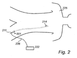
- guide wire 201 such as is illustrated in Fig. 1 , is schematically shown in Fig. 2 .
- Guide wire 201 is inserted into the femoral artery of a patient 225.
- the position of guide wire 201 and the sensor 214 inside the body is illustrated with dotted lines.
- Guide wire 201, and more specifically electrically transmitting cable 211 thereof, is also coupled to a control unit 222 via a wire 226 that is connected to cable 211 using any suitable connector means (not shown), such as a crocodile clip-type connector or any other known connector.
- the wire 226 is preferably made as short as possible for easiness in handling the guide wire 201.
- the wire 226 is omitted, such that the control unit 222 is directly attached to the cable 211 via suitable connectors.
- the control unit 222 provides an electrical voltage to the circuit comprising wire 226, cable 211 of the guide wire 201 and the sensor 214.
- the signal representing the measured physiological variable is transferred from the sensor 214 via the cable 211 to the control unit 222.
- the method to introduce the guide wire 201 is well known to those skilled in the art. From the control unit 222, a signal representing distal pressure measured by the sensor 214 is communicated to one or more monitor devices, preferably using the ANSI/AAMI BP22-1994 standard, either by means of wireless communication or via a wired connection.
- the voltage provided to the sensor by the control unit could be an AC or a DC voltage.
- the sensor is typically connected to a circuit that includes a rectifier that transforms the AC voltage to a DC voltage for driving the sensor selected to be sensitive to the physical parameter to be investigated.
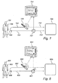
- Fig. 3 illustrates how measurements of FFR are undertaken today using the sensor discussed in connection with Figs. 1 and 2 .
- a first sensor 308 (not disposed in the patient) measures aortic blood pressure P a in known manner.
- a second sensor 309 is inserted into the patient 301 for measuring distal blood pressure P d .
- a communication link comprising channel 302 for carrying the distal pressure and channel 303 for carrying the aortic pressure is arranged between the sensors and a second monitoring device 304, for example a RadiAnalyzer ® .
- the RadiAnalyzer ® is used to analyze the data received from one or both sensors and therafter display data to the user.
- the receiving function in the present invention can be coupled to or integrated into such a unit.
- the respective channel is coupled to a central monitoring device 305 also referred to as a cathlab monitor.
- the two pressure types are used to calculate the FFR as P d /P a .
- the prior art approach has drawbacks; connecting the second, smaller monitoring device to an up-and-running system requires disconnection of connectors carrying pressure signals to the cathlab monitor and reconnection of these connectors to the cathlab monitor via the smaller monitor. Further, the disconnection of pressure signal connectors implies recalibrating of the monitors, which is an undesired step.
- the second monitoring device 304 must be calibrated with respect to the distal pressure channel 302.
- the second monitoring device 304 must be calibrated with respect to the aortic pressure chancel 303.
- the second monitoring device 304 and the first monitoring device 305 must be balanced, implying that both pressure channels 302, 303 running between the monitors is zeroed. This totals a number of four calibrating/balancing steps.
- Fig. 4 shows an example mitigating mentioned problems in the prior art.
- distal pressure channel 402 carries the signal measured in patient 401 by internal sensor 409 via a wired connection through control unit 406.
- Control unit 406 can perform signal conditioning (to be described below) and send the distal pressure signal to an eavesdropping receiver 404 and central monitor 405.
- signal conditioning can be performed by eavesdropping receiver 404 (in such an embodiment, functions of unit 406 are incorporated into the eavesdropping receiver and thus channel 402 is connected from the patient to the eavesdropping receiver and then from the receiver to monitor 405).
- a suitable control unit is a connector for a sensor guidewire assembly, such as the female connector for PressureWire ® , however other control units can also be used.
- the signal representing measured distal pressure is transmitted to the eavesdropping receiver 404 and the central monitor 405 using wired distal pressure channel 402, and the signal representing aortic pressure measured by external sensor 408 in this particular embodiment is transferred to both the receiver 404 and the central monitor 405 using a wired channel 403.
- a wired communication interface 407 of the inventive eavesdropping device is arranged at an appropriate location along the aortic channel 403, for example at an input of the central monitoring device 405, a wired communication interface 407 of the inventive eavesdropping device is arranged.
- the eavesdropping interface 407 transmits the signal representing measured aortic pressure to the eavesdropping receiver 404.
- the interface 407 can electrically tap into a conductor in channel 403 via a high-impedance device (such as a resistor). Alternatively, the interface 407 can sense the electrical signal in channel 403 by sensing the magnetic and/or electric field in the vicinity of channel 403 that is created by the electrical signal passing through the conductor in channel 403. Since the eavesdropping interface 407 is arranged with a high-impedance input, the eavesdropping does not affect the signal carried over the aortic channel 403. Thus, with the eavesdropping device of the present example, only three calibrating/balancing steps are required, since there is no need to calibrate the eavesdropped signal.
- a high-impedance device such as a resistor
- the cathlab monitor is up-and-running, there is no need to make any disconnections in order to couple the eavesdropping monitor (i.e. typically a RadiAnalyzer ® ) to the central (cathlab) monitor.
- the eavesdropping receiver 404 is connected to the communication link comprising distal channel 402 and aortic channel 403, in parallel with the central monitor 405, which greatly facilitates operation for the medical personnel.
- the wired communication interface 407 is preferably pre-mounted on the standard communication cables for connecting an aortic pressure sensor 408 to a central monitor 405, such cables and connectors being known in the art, but can also be designed to be easily connectable to such cables, e.g. by providing an assembly comprising suitable connectors and the transmitting unit. In the latter event, the connectors of the aortic channel 403 to the central monitor 405 are disconnected and reconnected via the provided assembly. In such a procedure, reconnection of cables is necessary, however, no new calibration is needed.
- Fig. 5 shows an embodiment of the present invention mitigating mentioned problems in the prior art.
- distal pressure charnel 502 carries the signal measured in patient 501 by internal sensor 509 via a wired connection through control unit 506.
- the signal representing measured distal pressure is transmitted to the eavesdropping receiver 504 and the central monitor 505 using wired distal pressure channel 502, and the signal representing aortic pressure measured by external sensor 508 in this particular embodiment is transferred to the central monitor 505 using a wired channel 503.
- a wireless communication interface 507 of the inventive eavesdropping device is arranged.
- the wireless eavesdropping interface 507 transmits the signal representing measured aortic pressure to the eavesdropping receiver 504, which is capable of wireless communication. Since the eavesdropping interface 507 is arranged with a high-impedance input, the eavesdropping does not affect the signal carried over the aortic channel 503. Thus, with the eavesdropping device of the present embodiment, only three calibrating/balancing steps are required, since there is no need to calibrate the eavesdropped signal. Further, if the cathlab monitor is up-and-running, there is no need to make any disconnections in order to couple the eavesdropping receiver (i.e. typically a RadiAnalyzer ® ) to the central (cathlab) monitor. As can be seen from Fig. 5 , the eavesdropping monitor 504 is connected to the communication link comprising distal channel 502 and aortic channel 503, in parallel with the central monitor 505, which greatly facilitates operation for the medical personnel.
- Fig. 6 shows another embodiment of the present invention mitigating mentioned problems in the prior art.
- distal pressure channel 602 carrying the signal measured in patient 601 by internal sensor 609 is wireless, which is enabled by means of control unit 606 transmitting in compliance with ANSI/AAMI Bop22-1994.
- a suitable control unit is the control unit for PressureWire Aeris ® , however other units may be used.
- the signal representing measured distal pressure is transmitted to the eavesdropping receiver 604 and the central monitor 605 using wireless distal pressure channel 602, while the signal representing aortic pressure measured by external sensor 608 in this particular embodiment is transferred to the central monitor 605 using a wired channel 603.
- Fig. 6 shows another embodiment of the present invention mitigating mentioned problems in the prior art.
- distal pressure channel 602 carrying the signal measured in patient 601 by internal sensor 609 is wireless, which is enabled by means of control unit 606 transmitting in compliance with ANSI/AAMI Bop22-1994.
- a suitable control unit is the control unit
- the central monitor is capable of wireless communication, possibly using a dongle attached to a monitor input and being adapted for communication with the control unit 606.
- a wireless communication interface 607 of the inventive eavesdropping device is arranged at an appropriate location along the aortic channel 603, for example at an input of the central monitoring device 605, a wireless communication interface 607 of the inventive eavesdropping device is arranged.
- the wireless eavesdropping interface 607 transmits the signal representing measured aortic pressure to the eavesdropping receiver 604, which is capable of wireless communication. Since the eavesdropping interface 607 is arranged with a high-impedance input, the eavesdropping does not affect the signal carried over the aortic channel 603.
- the eavesdropping device of the present embodiment only three calibrating/balancing steps are required, since there is no need to calibrate the eavesdropped signal.
- the cathlab monitor is up-and-running, there is no need to make any disconnections in order to couple the eavesdropping receiver (i.e. typically a RadiAnalyzer®) to the central (cathlab) monitor.
- the eavesdropping receiver 604 is connected to the communication link comprising distal channel 602 and aortic channel 603, in parallel with the central monitor 605, which greatly facilitates operation for the medical personnel.
- Fig. 7 shows another example mitigating mentioned problems in the prior art.
- distal pressure channel 702 carrying the signal measured in patient 701 by internal sensor 709 is wireless, which is enabled by means of control unit 706 transmitting in compliance with ANSI/AAMI BP22-1994.
- the signal representing measured distal pressure is transmitted to the eavesdropping receiver 704 and the central monitor 705 using a wireless portion of distal pressure channel 702, while the signal representing aortic pressure measured by external sensor 708 in this particular embodiment is transferred to the central monitor 705 as well as the eavesdropping receiver 704 using a wired channel 703.
- a wired communication interface 707 of the eavesdropping device is arranged at an appropriate location along the aortic channel 703, for example at an input of the central monitoring device 705, a wired communication interface 707 of the eavesdropping device is arranged.
- the eavesdropping interface 707 transmits the signal representing measured aortic pressure to the eavesdropping receiver 704. Since the eavesdropping interface 707 is arranged with a high-impedance input, the eavesdropping does not affect the signal carried over the aortic channel 703. Thus, with the eavesdropping device of the present example, only three calibrating/balancing steps are required, since there is no need to calibrate the eavesdropped signal.
- the cathiab monitor is up-and-running, there is no need to make any disconnections in order to couple the eavesdropping receiver to the central monitor.
- the eavesdropping receiver 704 is connected to the communication link comprising distal channel 702 and aortic channel 703, in parallel with the central monitor 705, which greatly facilitates operation for the medical personnel.
- the communication interface may be supplied with power from the central monitoring device.
- the medical personnel can connect a cable on which the communication interface is arranged to the central monitoring device without having to think about coupling an external power supply to the communication interface.
- the communication interface is arranged with a battery for supply of power.
- the communication interface can be arranged with a rechargable battery, which may be charged by the central monitoring device.
- Fig. 8 shows yet a further example mitigating mentioned problems in the prior art.
- distal pressure channel 802 carrying the signal measured in patient 801 by internal sensor 809 is wireless, which is enabled by means of control unit z transmitting in compliance with ANSI/AAMI BP22-1994.
- the signal representing measured distal pressure is transmitted to the eavesdropping receiver 804 and the central monitor 805 using a wireless portion of distal pressure channel 802.
- the signal representing aortic pressure measured by external sensor 808 is transferred to the eavesdropping receiver 804 and the central monitor 805 using a wireless portion of channel 803.
- a wireless communication interface 807 of the inventive eavesdropping device is arranged at an appropriate location along the aortic channel 803, a wireless communication interface 807 of the inventive eavesdropping device is arranged.
- the wireless eavesdropping interface 807 transmits the signal representing measured aortic pressure to the eavesdropping receiver 804 and the central monitoring device 805, which both are capable of wireless communication.
- the receiver and the central monitors can each use a dongle attached to a respective input and being adapted for wireless communication with the communication interface 807. Since the eavesdropping interface 807 is arranged with a high-impedance input, the eavesdropping does not affect the signal carried over the aortic channel 803.
- the eavesdropping device of the present example again only three calibrating/balancing steps are required, since there is no need to calibrate the eavesdropped signal.
- the cathlab monitor is up-and-running, there is no need to make any disconnections in order to couple the eavesdropping receiver to the central monitor.
- the eavesdropping receiver 804 is connected to the communication link comprising distal channel 802 and aortic channel 803, in parallel with the central monitor 805, which greatly facilitates operation for the medical personnel.
- the distal pressure signal is converted by a signal conversion unit arranged on the distal pressure channel of the communication link such that the converted signal, i.e. the output of the signal conversion unit, complies with the communication standard used.
- the signal conversion unit is typically arranged at a guide wire connector.
- the eavesdropping receiver is typically connected to the signal conversion unit, either by wire or wireless, for receiving the measured signal representing distal pressure. This requires calibration.
- the eavesdropping receiver is connected to the aortic pressure channel of the communication link via a high-impedance input into the eavesdropping interface, thus making it possible for the receiver to eavesdrop on the aortic pressure channel.
- the eavesdropping does not require calibration.
- the eavesdropping receiver can be connected to both the aortic and distal pressure channel via a respective high-impedance input, either by means of wired or wireless connections. Consequently, it is possible for the receiver of the eavesdropping device to eavesdrop on the aortic and the distal pressure channel. Again, the eavesdropping does not require calibration. With such a configuration, the eavesdropping device of the present invention would require only two calibration steps; the calibration of the distal and aortic pressure channels against the central monitoring device.
Claims (10)
- Ensemble d'écoute pour acquérir une variable physiologique mesurée d'un individu (501, 601), ledit ensemble comprenant :une interface de communication (507, 607) configurée pour être agencée le long d'un canal aortique câblé (503, 603), le canal aortique câblé (503, 603) s'étendant à partir (i) d'un capteur de pression aortique (508, 608) configuré pour mesurer la pression sanguine aortique et fournir un signal représentant la pression sanguine aortique mesurée, jusqu'à (ii) un dispositif de contrôle central (505, 605) configuré pour recevoir le signal représentant la pression sanguine aortique mesurée,un récepteur (504, 604) configuré pour recevoir le signal représentant la pression sanguine aortique mesurée et dans lequel le récepteur (504, 604) est en outre configuré pour analyser le signal représentant la pression sanguine aortique mesurée et afficher des informations se rapportant à la pression sanguine aortique mesurée en se basant sur ladite analyse, caractérisé en ce que le récepteur (504, 604) est agencé dans un logement distinct de l'interface de communication (507, 607) ; etl'interface de communication (507, 607) est configurée pour écouter sur le signal représentant la pression sanguine aortique mesurée sans affecter le signal transporté sur le canal aortique câblé (503, 603),l'interface de communication (507, 607) est configurée pour effectuer au moins un (i) d'un piquage électrique sur un conducteur du canal aortique câblé (503, 603) via un dispositif à haute impédance et (ii) d'une détection d'au moins un d'un champ magnétique et d'un champ électrique au voisinage du canal aortique câblé (503, 603) qui est créé par le signal passant à travers un conducteur du canal aortique câblé (503, 603), etl'interface de communication (507, 607) est configurée pour transmettre le signal représentant le signal de pression sanguine aortique mesuré au récepteur (504, 604), via une connexion sans fil entre l'interface de communication (507, 607) et le récepteur (504, 604).
- Système pour acquérir une variable physiologique mesurée d'un individu (501, 601), ledit système comprenant
un ensemble d'écoute selon la revendication 1;
un capteur de pression aortique (508, 608) configuré pour mesurer la pression sanguine aortique de l'individu et fournir un signal représentant la pression sanguine aortique mesurée ;
un capteur de pression distale (509, 609) configuré pour mesurer la pression sanguine distale de l'individu et fournir un signal représentant la pression sanguine distale mesurée ;
un dispositif de contrôle central (505, 605) configuré pour recevoir le signal représentant la pression sanguine aortique mesurée ; et
une unité de commande (506, 606) configurée pour recevoir le signal représentant la pression sanguine distale mesurée via une connexion câblée entre le capteur de pression distale (509, 609) et l'unité de commande (506, 606), l'unité de commande étant distincte tant de l'interface de communication (507, 607) que du récepteur (504, 604) ;
dans lequel l'unité de commande (506, 606) est configurée pour envoyer le signal représentant la pression sanguine distale mesurée tant au récepteur (504, 604) qu'au dispositif de contrôle central (505, 605). - Système selon la revendication 2, dans lequel l'unité de commande (506) est configurée pour envoyer le signal représentant la pression sanguine distale mesurée au récepteur (504) via une connexion câblée entre l'unité de commande (506) et le récepteur (504), et
l'unité de commande (506) est configurée pour envoyer le signal représentant la pression sanguine distale mesurée au dispositif de contrôle central (505) via une connexion câblée entre l'unité de commande (506) et le dispositif de contrôle central (505). - Système selon la revendication 2, dans lequel l'unité de commande (606) est configurée pour envoyer le signal représentant la pression sanguine distale mesurée au récepteur (604) via une connexion sans fil entre l'unité de commande (606) et le récepteur (604), et
l'unité de commande (606) est configurée pour envoyer le signal représentant la pression sanguine distale mesurée au dispositif de contrôle central (605) via une connexion sans fil entre l'unité de commande (606) et le dispositif de contrôle central (605). - Système selon n'importe laquelle des revendications 2 à 4, dans lequel l'interface de communication (507, 607) est agencée pour être alimentée en énergie à partir du dispositif de contrôle central (505, 605).
- Système selon n'importe laquelle des revendications 2 à 4, dans lequel l'interface de communication (507, 607) est agencée avec au moins une batterie pour l'alimentation en énergie.
- Système selon la revendication 6, dans lequel l'interface de communication (507, 607) est agencée de sorte qu'au moins une batterie peut être chargée à partir du dispositif de contrôle central (505, 605).
- Système selon n'importe laquelle des revendications 2 à 4, dans lequel le dispositif à haute impédance comprend une résistance.
- Système selon n'importe laquelle des revendications 2 à 8, dans lequel l'interface de communication (507, 607) est montée à l'avance sur un câble de communication standard pour relier le capteur de pression aortique (508, 608) au dispositif de contrôle central (505, 605).
- Système selon n'importe laquelle des revendications 2 à 8, dans lequel l'interface de communication (507, 607) peut être reliée à un câble de communication standard pour relier le capteur de pression aortique (508, 608) au dispositif de contrôle central (505, 605), de sorte que les connecteurs du canal aortique câblé (503, 603) au dispositif de contrôle central (505, 605) peuvent être déconnectés et reconnectés via l'interface de communication (507, 607).
Priority Applications (20)
| Application Number | Priority Date | Filing Date | Title |
|---|---|---|---|
| ES15200395.0T ES2635643T3 (es) | 2009-09-18 | 2009-09-18 | Dispositivo para adquirir variables fisiológicas medidas en un cuerpo |
| ES09170637.4T ES2569605T3 (es) | 2009-09-18 | 2009-09-18 | Dispositivo para adquirir variables fisiológicas medidas en un cuerpo |
| EP09170637.4A EP2298162B1 (fr) | 2009-09-18 | 2009-09-18 | Dispositif pour l'acquisition de variables physiologiques mesurées dans un corps |
| ES17176158T ES2732430T3 (es) | 2009-09-18 | 2009-09-18 | Sistema para adquirir variables fisiológicas medidas en un cuerpo |
| EP15200395.0A EP3011898B1 (fr) | 2009-09-18 | 2009-09-18 | Dispositif pour l'acquisition de variables physiologiques mesurées dans un corps |
| EP17176158.8A EP3238613B1 (fr) | 2009-09-18 | 2009-09-18 | Système d'acquisition de variables physiologiques mesurées dans un corps |
| EP19165526.5A EP3520689A1 (fr) | 2009-09-18 | 2009-09-18 | Système d'acquisition de variables physiologiques mesurées dans un corps |
| AU2010297345A AU2010297345B2 (en) | 2009-09-18 | 2010-09-16 | Eavesdropping device |
| JP2012529265A JP5688086B2 (ja) | 2009-09-18 | 2010-09-16 | 傍受装置 |
| CA2964533A CA2964533C (fr) | 2009-09-18 | 2010-09-16 | Dispositif d'auscultation |
| CA2772966A CA2772966C (fr) | 2009-09-18 | 2010-09-16 | Dispositif d'auscultation |
| PCT/EP2010/063586 WO2011033007A1 (fr) | 2009-09-18 | 2010-09-16 | Dispositif d'auscultation |
| JP2015011601A JP5996680B2 (ja) | 2009-09-18 | 2015-01-23 | 傍受装置 |
| JP2016084507A JP6259004B2 (ja) | 2009-09-18 | 2016-04-20 | 傍受装置 |
| JP2017126348A JP6325724B2 (ja) | 2009-09-18 | 2017-06-28 | 傍受装置 |
| JP2017235230A JP6523420B2 (ja) | 2009-09-18 | 2017-12-07 | 傍受装置 |
| JP2019083788A JP6776398B2 (ja) | 2009-09-18 | 2019-04-25 | 血圧測定および通信システム |
| JP2020169848A JP7005721B2 (ja) | 2009-09-18 | 2020-10-07 | 血圧測定および通信システム |
| JP2022000476A JP7277618B2 (ja) | 2009-09-18 | 2022-01-05 | システム |
| JP2023076503A JP2023109806A (ja) | 2009-09-18 | 2023-05-08 | 傍受装置 |
Applications Claiming Priority (1)
| Application Number | Priority Date | Filing Date | Title |
|---|---|---|---|
| EP09170637.4A EP2298162B1 (fr) | 2009-09-18 | 2009-09-18 | Dispositif pour l'acquisition de variables physiologiques mesurées dans un corps |
Related Child Applications (4)
| Application Number | Title | Priority Date | Filing Date |
|---|---|---|---|
| EP17176158.8A Division EP3238613B1 (fr) | 2009-09-18 | 2009-09-18 | Système d'acquisition de variables physiologiques mesurées dans un corps |
| EP19165526.5A Division EP3520689A1 (fr) | 2009-09-18 | 2009-09-18 | Système d'acquisition de variables physiologiques mesurées dans un corps |
| EP15200395.0A Division EP3011898B1 (fr) | 2009-09-18 | 2009-09-18 | Dispositif pour l'acquisition de variables physiologiques mesurées dans un corps |
| EP15200395.0A Division-Into EP3011898B1 (fr) | 2009-09-18 | 2009-09-18 | Dispositif pour l'acquisition de variables physiologiques mesurées dans un corps |
Publications (2)
| Publication Number | Publication Date |
|---|---|
| EP2298162A1 EP2298162A1 (fr) | 2011-03-23 |
| EP2298162B1 true EP2298162B1 (fr) | 2016-03-09 |
Family
ID=41490362
Family Applications (4)
| Application Number | Title | Priority Date | Filing Date |
|---|---|---|---|
| EP17176158.8A Active EP3238613B1 (fr) | 2009-09-18 | 2009-09-18 | Système d'acquisition de variables physiologiques mesurées dans un corps |
| EP19165526.5A Pending EP3520689A1 (fr) | 2009-09-18 | 2009-09-18 | Système d'acquisition de variables physiologiques mesurées dans un corps |
| EP09170637.4A Active EP2298162B1 (fr) | 2009-09-18 | 2009-09-18 | Dispositif pour l'acquisition de variables physiologiques mesurées dans un corps |
| EP15200395.0A Active EP3011898B1 (fr) | 2009-09-18 | 2009-09-18 | Dispositif pour l'acquisition de variables physiologiques mesurées dans un corps |
Family Applications Before (2)
| Application Number | Title | Priority Date | Filing Date |
|---|---|---|---|
| EP17176158.8A Active EP3238613B1 (fr) | 2009-09-18 | 2009-09-18 | Système d'acquisition de variables physiologiques mesurées dans un corps |
| EP19165526.5A Pending EP3520689A1 (fr) | 2009-09-18 | 2009-09-18 | Système d'acquisition de variables physiologiques mesurées dans un corps |
Family Applications After (1)
| Application Number | Title | Priority Date | Filing Date |
|---|---|---|---|
| EP15200395.0A Active EP3011898B1 (fr) | 2009-09-18 | 2009-09-18 | Dispositif pour l'acquisition de variables physiologiques mesurées dans un corps |
Country Status (2)
| Country | Link |
|---|---|
| EP (4) | EP3238613B1 (fr) |
| ES (3) | ES2635643T3 (fr) |
Cited By (1)
| Publication number | Priority date | Publication date | Assignee | Title |
|---|---|---|---|---|
| US9339348B2 (en) | 2011-08-20 | 2016-05-17 | Imperial Colege of Science, Technology and Medicine | Devices, systems, and methods for assessing a vessel |
Families Citing this family (8)
| Publication number | Priority date | Publication date | Assignee | Title |
|---|---|---|---|---|
| GB201100137D0 (en) | 2011-01-06 | 2011-02-23 | Davies Helen C S | Apparatus and method of assessing a narrowing in a fluid tube |
| RU2014110702A (ru) | 2011-08-20 | 2015-09-27 | Волкано Корпорэйшн | Устройства, системы и способы визуального отображения сосуда и оценки вариантов лечения |
| CN103300820A (zh) * | 2012-03-13 | 2013-09-18 | 西门子公司 | 用于冠状动脉狭窄的非侵入性功能评估的方法和系统 |
| US9974443B2 (en) | 2014-02-20 | 2018-05-22 | Koninklijke Philips N.V. | Devices, systems, and methods and associated display screens for assessment of vessels |
| WO2015164250A1 (fr) | 2014-04-21 | 2015-10-29 | Koninklijke Philips N.V. | Dispositifs, systèmes et procédés intravasculaires ayant des sections distinctes avec des éléments centraux en prise |
| US10849511B2 (en) | 2014-07-14 | 2020-12-01 | Philips Image Guided Therapy Corporation | Devices, systems, and methods for assessment of vessels |
| WO2016008809A1 (fr) | 2014-07-15 | 2016-01-21 | Koninklijke Philips N.V. | Dispositifs, systèmes et procédés et écrans d'affichage associés pour l'évaluation de récipients avec de multiples composants de détection |
| US11395597B2 (en) * | 2018-06-26 | 2022-07-26 | General Electric Company | System and method for evaluating blood flow in a vessel |
Citations (4)
| Publication number | Priority date | Publication date | Assignee | Title |
|---|---|---|---|---|
| US5703928A (en) * | 1995-09-26 | 1997-12-30 | Industrial Technology, Inc. | Probe for sampling differential electromagnetic fields |
| EP1292045A2 (fr) * | 2001-08-29 | 2003-03-12 | Sensor Technologies, Inc. | Détecteur d'analyseur |
| US20050275397A1 (en) * | 2004-06-15 | 2005-12-15 | Power Measurement, Ltd. | Non-intrusive power monitor |
| EP2039286A1 (fr) * | 2007-09-21 | 2009-03-25 | Roche Diagnostics GmbH | Dispositif d'interface entre une unité de gestion de données et un dispositif médical |
Family Cites Families (7)
| Publication number | Priority date | Publication date | Assignee | Title |
|---|---|---|---|---|
| US5568815A (en) * | 1994-11-21 | 1996-10-29 | Becton Dickinson And Company | Self-powered interface circuit for use with a transducer sensor |
| SE9600333D0 (sv) | 1995-06-22 | 1996-01-30 | Radi Medical Systems | Sensor arrangement |
| SE9600334D0 (sv) | 1996-01-30 | 1996-01-30 | Radi Medical Systems | Combined flow, pressure and temperature sensor |
| WO1999034724A2 (fr) * | 1998-01-12 | 1999-07-15 | Florence Medical Ltd. | Systeme et procede pour caracteriser des lesions et des parois de vaisseaux sanguins au moyen de mesures de pression en plusieurs points |
| US6615067B2 (en) | 2000-03-21 | 2003-09-02 | Radi Medical Systems Ab | Method and device for measuring physical characteristics in a body |
| US6585660B2 (en) * | 2001-05-18 | 2003-07-01 | Jomed Inc. | Signal conditioning device for interfacing intravascular sensors having varying operational characteristics to a physiology monitor |
| EP1774905B1 (fr) * | 2005-10-12 | 2014-12-03 | Radi Medical Systems Ab | Fil détecteur. |
-
2009
- 2009-09-18 ES ES15200395.0T patent/ES2635643T3/es active Active
- 2009-09-18 ES ES17176158T patent/ES2732430T3/es active Active
- 2009-09-18 ES ES09170637.4T patent/ES2569605T3/es active Active
- 2009-09-18 EP EP17176158.8A patent/EP3238613B1/fr active Active
- 2009-09-18 EP EP19165526.5A patent/EP3520689A1/fr active Pending
- 2009-09-18 EP EP09170637.4A patent/EP2298162B1/fr active Active
- 2009-09-18 EP EP15200395.0A patent/EP3011898B1/fr active Active
Patent Citations (4)
| Publication number | Priority date | Publication date | Assignee | Title |
|---|---|---|---|---|
| US5703928A (en) * | 1995-09-26 | 1997-12-30 | Industrial Technology, Inc. | Probe for sampling differential electromagnetic fields |
| EP1292045A2 (fr) * | 2001-08-29 | 2003-03-12 | Sensor Technologies, Inc. | Détecteur d'analyseur |
| US20050275397A1 (en) * | 2004-06-15 | 2005-12-15 | Power Measurement, Ltd. | Non-intrusive power monitor |
| EP2039286A1 (fr) * | 2007-09-21 | 2009-03-25 | Roche Diagnostics GmbH | Dispositif d'interface entre une unité de gestion de données et un dispositif médical |
Cited By (1)
| Publication number | Priority date | Publication date | Assignee | Title |
|---|---|---|---|---|
| US9339348B2 (en) | 2011-08-20 | 2016-05-17 | Imperial Colege of Science, Technology and Medicine | Devices, systems, and methods for assessing a vessel |
Also Published As
| Publication number | Publication date |
|---|---|
| EP3011898B1 (fr) | 2017-07-05 |
| ES2635643T3 (es) | 2017-10-04 |
| ES2732430T3 (es) | 2019-11-22 |
| EP3238613A1 (fr) | 2017-11-01 |
| ES2569605T3 (es) | 2016-05-11 |
| EP3238613B1 (fr) | 2019-05-08 |
| EP2298162A1 (fr) | 2011-03-23 |
| EP3011898A1 (fr) | 2016-04-27 |
| EP3520689A1 (fr) | 2019-08-07 |
Similar Documents
| Publication | Publication Date | Title |
|---|---|---|
| US11452451B2 (en) | Device for acquiring physiological variables measured in a body | |
| EP2298162B1 (fr) | Dispositif pour l'acquisition de variables physiologiques mesurées dans un corps | |
| JP7277618B2 (ja) | システム | |
| US8698638B2 (en) | Transceiver unit in a measurement system | |
| EP1922988B1 (fr) | Unité émetteur-récepteur dans un système de mesure de la pression sanguine | |
| US11234650B2 (en) | Measurement system |
Legal Events
| Date | Code | Title | Description |
|---|---|---|---|
| PUAI | Public reference made under article 153(3) epc to a published international application that has entered the european phase |
Free format text: ORIGINAL CODE: 0009012 |
|
| 17P | Request for examination filed |
Effective date: 20090918 |
|
| AK | Designated contracting states |
Kind code of ref document: A1 Designated state(s): AT BE BG CH CY CZ DE DK EE ES FI FR GB GR HR HU IE IS IT LI LT LU LV MC MK MT NL NO PL PT RO SE SI SK SM TR |
|
| 17Q | First examination report despatched |
Effective date: 20140903 |
|
| GRAP | Despatch of communication of intention to grant a patent |
Free format text: ORIGINAL CODE: EPIDOSNIGR1 |
|
| RAP1 | Party data changed (applicant data changed or rights of an application transferred) |
Owner name: ST. JUDE MEDICAL COORDINATION CENTER BVBA |
|
| INTG | Intention to grant announced |
Effective date: 20150903 |
|
| GRAS | Grant fee paid |
Free format text: ORIGINAL CODE: EPIDOSNIGR3 |
|
| GRAA | (expected) grant |
Free format text: ORIGINAL CODE: 0009210 |
|
| AK | Designated contracting states |
Kind code of ref document: B1 Designated state(s): AT BE BG CH CY CZ DE DK EE ES FI FR GB GR HR HU IE IS IT LI LT LU LV MC MK MT NL NO PL PT RO SE SI SK SM TR |
|
| REG | Reference to a national code |
Ref country code: GB Ref legal event code: FG4D |
|
| REG | Reference to a national code |
Ref country code: AT Ref legal event code: REF Ref document number: 778863 Country of ref document: AT Kind code of ref document: T Effective date: 20160315 Ref country code: CH Ref legal event code: EP |
|
| REG | Reference to a national code |
Ref country code: IE Ref legal event code: FG4D |
|
| REG | Reference to a national code |
Ref country code: DE Ref legal event code: R096 Ref document number: 602009036650 Country of ref document: DE |
|
| REG | Reference to a national code |
Ref country code: ES Ref legal event code: FG2A Ref document number: 2569605 Country of ref document: ES Kind code of ref document: T3 Effective date: 20160511 |
|
| REG | Reference to a national code |
Ref country code: LT Ref legal event code: MG4D |
|
| REG | Reference to a national code |
Ref country code: NL Ref legal event code: MP Effective date: 20160309 |
|
| PG25 | Lapsed in a contracting state [announced via postgrant information from national office to epo] |
Ref country code: HR Free format text: LAPSE BECAUSE OF FAILURE TO SUBMIT A TRANSLATION OF THE DESCRIPTION OR TO PAY THE FEE WITHIN THE PRESCRIBED TIME-LIMIT Effective date: 20160309 Ref country code: NO Free format text: LAPSE BECAUSE OF FAILURE TO SUBMIT A TRANSLATION OF THE DESCRIPTION OR TO PAY THE FEE WITHIN THE PRESCRIBED TIME-LIMIT Effective date: 20160609 Ref country code: GR Free format text: LAPSE BECAUSE OF FAILURE TO SUBMIT A TRANSLATION OF THE DESCRIPTION OR TO PAY THE FEE WITHIN THE PRESCRIBED TIME-LIMIT Effective date: 20160610 Ref country code: FI Free format text: LAPSE BECAUSE OF FAILURE TO SUBMIT A TRANSLATION OF THE DESCRIPTION OR TO PAY THE FEE WITHIN THE PRESCRIBED TIME-LIMIT Effective date: 20160309 |
|
| REG | Reference to a national code |
Ref country code: AT Ref legal event code: MK05 Ref document number: 778863 Country of ref document: AT Kind code of ref document: T Effective date: 20160309 |
|
| PG25 | Lapsed in a contracting state [announced via postgrant information from national office to epo] |
Ref country code: PL Free format text: LAPSE BECAUSE OF FAILURE TO SUBMIT A TRANSLATION OF THE DESCRIPTION OR TO PAY THE FEE WITHIN THE PRESCRIBED TIME-LIMIT Effective date: 20160309 Ref country code: LT Free format text: LAPSE BECAUSE OF FAILURE TO SUBMIT A TRANSLATION OF THE DESCRIPTION OR TO PAY THE FEE WITHIN THE PRESCRIBED TIME-LIMIT Effective date: 20160309 Ref country code: SE Free format text: LAPSE BECAUSE OF FAILURE TO SUBMIT A TRANSLATION OF THE DESCRIPTION OR TO PAY THE FEE WITHIN THE PRESCRIBED TIME-LIMIT Effective date: 20160309 Ref country code: LV Free format text: LAPSE BECAUSE OF FAILURE TO SUBMIT A TRANSLATION OF THE DESCRIPTION OR TO PAY THE FEE WITHIN THE PRESCRIBED TIME-LIMIT Effective date: 20160309 Ref country code: NL Free format text: LAPSE BECAUSE OF FAILURE TO SUBMIT A TRANSLATION OF THE DESCRIPTION OR TO PAY THE FEE WITHIN THE PRESCRIBED TIME-LIMIT Effective date: 20160309 |
|
| REG | Reference to a national code |
Ref country code: FR Ref legal event code: PLFP Year of fee payment: 8 |
|
| PG25 | Lapsed in a contracting state [announced via postgrant information from national office to epo] |
Ref country code: IS Free format text: LAPSE BECAUSE OF FAILURE TO SUBMIT A TRANSLATION OF THE DESCRIPTION OR TO PAY THE FEE WITHIN THE PRESCRIBED TIME-LIMIT Effective date: 20160709 Ref country code: EE Free format text: LAPSE BECAUSE OF FAILURE TO SUBMIT A TRANSLATION OF THE DESCRIPTION OR TO PAY THE FEE WITHIN THE PRESCRIBED TIME-LIMIT Effective date: 20160309 |
|
| PG25 | Lapsed in a contracting state [announced via postgrant information from national office to epo] |
Ref country code: SK Free format text: LAPSE BECAUSE OF FAILURE TO SUBMIT A TRANSLATION OF THE DESCRIPTION OR TO PAY THE FEE WITHIN THE PRESCRIBED TIME-LIMIT Effective date: 20160309 Ref country code: PT Free format text: LAPSE BECAUSE OF FAILURE TO SUBMIT A TRANSLATION OF THE DESCRIPTION OR TO PAY THE FEE WITHIN THE PRESCRIBED TIME-LIMIT Effective date: 20160711 Ref country code: AT Free format text: LAPSE BECAUSE OF FAILURE TO SUBMIT A TRANSLATION OF THE DESCRIPTION OR TO PAY THE FEE WITHIN THE PRESCRIBED TIME-LIMIT Effective date: 20160309 Ref country code: RO Free format text: LAPSE BECAUSE OF FAILURE TO SUBMIT A TRANSLATION OF THE DESCRIPTION OR TO PAY THE FEE WITHIN THE PRESCRIBED TIME-LIMIT Effective date: 20160309 Ref country code: CZ Free format text: LAPSE BECAUSE OF FAILURE TO SUBMIT A TRANSLATION OF THE DESCRIPTION OR TO PAY THE FEE WITHIN THE PRESCRIBED TIME-LIMIT Effective date: 20160309 Ref country code: SM Free format text: LAPSE BECAUSE OF FAILURE TO SUBMIT A TRANSLATION OF THE DESCRIPTION OR TO PAY THE FEE WITHIN THE PRESCRIBED TIME-LIMIT Effective date: 20160309 |
|
| REG | Reference to a national code |
Ref country code: DE Ref legal event code: R097 Ref document number: 602009036650 Country of ref document: DE |
|
| PG25 | Lapsed in a contracting state [announced via postgrant information from national office to epo] |
Ref country code: BE Free format text: LAPSE BECAUSE OF FAILURE TO SUBMIT A TRANSLATION OF THE DESCRIPTION OR TO PAY THE FEE WITHIN THE PRESCRIBED TIME-LIMIT Effective date: 20160309 |
|
| PLBE | No opposition filed within time limit |
Free format text: ORIGINAL CODE: 0009261 |
|
| STAA | Information on the status of an ep patent application or granted ep patent |
Free format text: STATUS: NO OPPOSITION FILED WITHIN TIME LIMIT |
|
| PG25 | Lapsed in a contracting state [announced via postgrant information from national office to epo] |
Ref country code: DK Free format text: LAPSE BECAUSE OF FAILURE TO SUBMIT A TRANSLATION OF THE DESCRIPTION OR TO PAY THE FEE WITHIN THE PRESCRIBED TIME-LIMIT Effective date: 20160309 |
|
| 26N | No opposition filed |
Effective date: 20161212 |
|
| PG25 | Lapsed in a contracting state [announced via postgrant information from national office to epo] |
Ref country code: BG Free format text: LAPSE BECAUSE OF FAILURE TO SUBMIT A TRANSLATION OF THE DESCRIPTION OR TO PAY THE FEE WITHIN THE PRESCRIBED TIME-LIMIT Effective date: 20160609 |
|
| PG25 | Lapsed in a contracting state [announced via postgrant information from national office to epo] |
Ref country code: MC Free format text: LAPSE BECAUSE OF FAILURE TO SUBMIT A TRANSLATION OF THE DESCRIPTION OR TO PAY THE FEE WITHIN THE PRESCRIBED TIME-LIMIT Effective date: 20160309 |
|
| REG | Reference to a national code |
Ref country code: CH Ref legal event code: PL |
|
| PG25 | Lapsed in a contracting state [announced via postgrant information from national office to epo] |
Ref country code: SI Free format text: LAPSE BECAUSE OF FAILURE TO SUBMIT A TRANSLATION OF THE DESCRIPTION OR TO PAY THE FEE WITHIN THE PRESCRIBED TIME-LIMIT Effective date: 20160309 |
|
| REG | Reference to a national code |
Ref country code: IE Ref legal event code: MM4A |
|
| PG25 | Lapsed in a contracting state [announced via postgrant information from national office to epo] |
Ref country code: CH Free format text: LAPSE BECAUSE OF NON-PAYMENT OF DUE FEES Effective date: 20160930 Ref country code: IE Free format text: LAPSE BECAUSE OF NON-PAYMENT OF DUE FEES Effective date: 20160918 Ref country code: LI Free format text: LAPSE BECAUSE OF NON-PAYMENT OF DUE FEES Effective date: 20160930 |
|
| PG25 | Lapsed in a contracting state [announced via postgrant information from national office to epo] |
Ref country code: LU Free format text: LAPSE BECAUSE OF NON-PAYMENT OF DUE FEES Effective date: 20160918 |
|
| REG | Reference to a national code |
Ref country code: FR Ref legal event code: PLFP Year of fee payment: 9 |
|
| PG25 | Lapsed in a contracting state [announced via postgrant information from national office to epo] |
Ref country code: CY Free format text: LAPSE BECAUSE OF FAILURE TO SUBMIT A TRANSLATION OF THE DESCRIPTION OR TO PAY THE FEE WITHIN THE PRESCRIBED TIME-LIMIT Effective date: 20160309 Ref country code: HU Free format text: LAPSE BECAUSE OF FAILURE TO SUBMIT A TRANSLATION OF THE DESCRIPTION OR TO PAY THE FEE WITHIN THE PRESCRIBED TIME-LIMIT; INVALID AB INITIO Effective date: 20090918 |
|
| PG25 | Lapsed in a contracting state [announced via postgrant information from national office to epo] |
Ref country code: MT Free format text: LAPSE BECAUSE OF NON-PAYMENT OF DUE FEES Effective date: 20160930 Ref country code: MK Free format text: LAPSE BECAUSE OF FAILURE TO SUBMIT A TRANSLATION OF THE DESCRIPTION OR TO PAY THE FEE WITHIN THE PRESCRIBED TIME-LIMIT Effective date: 20160309 Ref country code: TR Free format text: LAPSE BECAUSE OF FAILURE TO SUBMIT A TRANSLATION OF THE DESCRIPTION OR TO PAY THE FEE WITHIN THE PRESCRIBED TIME-LIMIT Effective date: 20160309 |
|
| REG | Reference to a national code |
Ref country code: FR Ref legal event code: PLFP Year of fee payment: 10 |
|
| P01 | Opt-out of the competence of the unified patent court (upc) registered |
Effective date: 20230623 |
|
| PGFP | Annual fee paid to national office [announced via postgrant information from national office to epo] |
Ref country code: IT Payment date: 20230913 Year of fee payment: 15 Ref country code: GB Payment date: 20230810 Year of fee payment: 15 |
|
| PGFP | Annual fee paid to national office [announced via postgrant information from national office to epo] |
Ref country code: FR Payment date: 20230807 Year of fee payment: 15 Ref country code: DE Payment date: 20230808 Year of fee payment: 15 |
|
| PGFP | Annual fee paid to national office [announced via postgrant information from national office to epo] |
Ref country code: ES Payment date: 20231011 Year of fee payment: 15 |