EP2298136A2 - Luftmatratze - Google Patents
Luftmatratze Download PDFInfo
- Publication number
- EP2298136A2 EP2298136A2 EP10173550A EP10173550A EP2298136A2 EP 2298136 A2 EP2298136 A2 EP 2298136A2 EP 10173550 A EP10173550 A EP 10173550A EP 10173550 A EP10173550 A EP 10173550A EP 2298136 A2 EP2298136 A2 EP 2298136A2
- Authority
- EP
- European Patent Office
- Prior art keywords
- air
- inlet
- distributors
- outlet
- mattress
- Prior art date
- Legal status (The legal status is an assumption and is not a legal conclusion. Google has not performed a legal analysis and makes no representation as to the accuracy of the status listed.)
- Granted
Links
Images


Classifications
-
- A—HUMAN NECESSITIES
- A47—FURNITURE; DOMESTIC ARTICLES OR APPLIANCES; COFFEE MILLS; SPICE MILLS; SUCTION CLEANERS IN GENERAL
- A47C—CHAIRS; SOFAS; BEDS
- A47C27/00—Spring, stuffed or fluid mattresses or cushions specially adapted for chairs, beds or sofas
- A47C27/08—Fluid mattresses
- A47C27/10—Fluid mattresses with two or more independently-fillable chambers
-
- A—HUMAN NECESSITIES
- A47—FURNITURE; DOMESTIC ARTICLES OR APPLIANCES; COFFEE MILLS; SPICE MILLS; SUCTION CLEANERS IN GENERAL
- A47C—CHAIRS; SOFAS; BEDS
- A47C27/00—Spring, stuffed or fluid mattresses or cushions specially adapted for chairs, beds or sofas
- A47C27/08—Fluid mattresses
- A47C27/081—Fluid mattresses of pneumatic type
- A47C27/082—Fluid mattresses of pneumatic type with non-manual inflation, e.g. with electric pumps
Definitions
- the present invention relates to an air mattress with air pressure control.
- Air mattresses are used with cots and beds to provide yieldable body support.
- the air mattresses are inflated with pumps, such as hand operated or bag pumps.
- Motor driven blowers and pumps have also been to supply air under pressure to air mattresses.
- the biasing or firmness characteristics of an air mattress is determined by the pressure of the air in the air mattresses.
- the air mattress firmness can be varied by supplying additional air or venting air from the air mattress.
- Control mechanisms have been used to adjust the inflation of the air mattress. Even better control mechanisms applied to the air mattresses are necessary when the air mattresses are designed for a patient who is confined on the air mattresses for an extended period of time.
- an air mattress includes at least two separate zones.
- a first and second groups of elongate, inflatable cells are disposed alternately within each of the at least two separate zones.
- An air pump is to supply pressurized air.
- At least two air distributors are serially connected with the air pump for respectively distributing the pressurized air to the at least two separate zones.
- Each air distributor is operable to supply the pressurized air to the first and second groups of cells within each of the at least two separate zones.
- a pressure reducer is serially connected between any adjacent two of the at least two distributors for reducing the pressure of the pressurized air to a downstream one of any adjacent two of the at least two distributors.
- the air pump is serially connected with several air pressure control devices to control multiple zones of an air mattress so as to reduce necessary air pressure control devices.
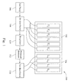
- Fig. 1 illustrates a block diagram of an air mattress with air pressure control according to one embodiment of this invention.
- the air mattress 100 with air pressure control includes two separate zones (102 and 104) or more, within each zone of which a first and second groups of elongate, inflatable cells, e.g. cells U 1 and cells U 2 in the zone 102 or cells L 1 and cells L 2 in the zone 104, are alternately arranged.
- the zone 102 may be designed for supporting a patent's upper body while the zone 104 may be designed for supporting a patent's lower body.
- the air mattress firmness of the zone 104 may be lower than that of the zone 102 such that the patent's lower body, e.g. legs or feet can be of comfortable support.
- An air pump 106 supplies pressurized air to the air mattress 100 and the pressure of the air in the air mattress is varied by various air pressure control devices, i.e. 108, 110, 112 and 114, illustrated in the drawings.
- two air distributors (108, 114) are serially connected with the air pump 106 for respectively distributing the pressurized air to the two separate zones (102, 104).
- Each air distributor (108 or 114) is operable to supply the pressurized air to the first and second groups of cells (U 1 and U 2 or L 1 and L 2 ) within each of the at least two separate zones. If the air mattress is divided into three or more zones, three or more distributors are needed to control respective zones.
- a pressure reducer 112 is serially connected between two distributors (108, 114) for reducing the pressure of the pressurized air to the downstream distributor 114. If there are three or more distributors, a pressure reducer is serially connected between any adjacent two of the three or more distributors for reducing the pressure of the pressurized air to a downstream one of any adjacent two distributors.
- a regulator 110 may be serially connected between the pressure reducer 112 and the upstream air distributor 108. If there are three or more distributors, a regulator is serially connected between the pressure reducer and an upstream one of any adjacent two of the three or more distributors.
- FIG. 2 illustrates a diagram of an air pump set for an air mattress according to another embodiment of this invention.
- An air pump 206 is to supply pressurized air.
- Two air distributors (208, 214) are serially connected with the air pump 206.
- a pressure reducer 212 is serially connected between two air distributors (208, 214) for reducing the pressure of the pressurized air to the downstream distributor 214.
- a regulator 210 may be serially connected between the pressure reducer 212 and the upstream air distributor 208.
- the air distributor 208 has an inlet and four outlets.
- the inlet 208a of the air distributor 208 is connected to the air pump 206 to receive the pressurized air.
- Two outlets (208b, 208c) are to distribute the pressurized air to respective air-requiring targets, e.g. inflatable cells U 1 and U 2 in Fig. 1 .
- An outlet 208e is connected to the regulator 210 or directly to the pressure reducer 212 (if the regulator 210 is not installed).
- An outlet 208d is to vent air out.
- the air distributor's operation mechanisms are illustrated and articulated in the embodiments of Fig.4A through Fig. 4D .
- the pressure reducer 212 has two pairs of inlets and outlets, i.e. inlet 212c, outlet 212b, inlet 212e and outlet 212d.
- a user may turn a knob 212a to switch the pressure reducer 212 between two pressure reducing ratios.
- the inlet 212c of the pressure reducer 212 is connected to the outlet 208e of the air distributor 208 (if the regulator 210 is not installed) or the regulator 210 whereas the outlet 212b of the pressure reducer 212 is connected to the downstream air distributor 214.
- the inlet 212e of the pressure reducer 212 is also connected to the downstream air distributor 214.
- the outlet 212d is to vent air out.
- the pressure reducer's detailed structures are illustrated and articulated in the embodiment of Fig.5 , and its operation mechanisms are illustrated and articulated in the embodiments of Fig. 5A and Fig. 5B .
- the air distributor 214 has an inlet and four outlets.
- the inlet 214a of the air distributor 214 is connected to both the inlet 212e and outlet 212b of the pressure reducer 212.
- Two outlets (214b, 214c) are to distribute the pressurized air to respective air-requiring targets, e.g. inflatable cells L 1 and L 2 in Fig. 1 .
- An outlet 214e is connected to a further air distributor or pressure reducer (if necessary), otherwise the outlet 214e may be sealed.
- An outlet 214d is to vent air out.
- the air distributor's operation mechanisms are illustrated and articulated in the embodiments of Fig.4A through Fig. 4D .
- the regulator 210 may be serially connected between the pressure reducer 212 and the upstream air distributor 208 to regulate down the pressure of all the pressurized air (supplied by the air pump 206) upstream the pressure reducer 212.
- FIG. 3 illustrates an air distributor module of the air mattress according to another embodiment of this invention
- Fig. 3A illustrates a side view of the air distributor module in Fig. 3
- the air distributor module 300 basically consists of two air distributors combined.
- Each air distributor consists of two disc-shaped halves, e.g. disc-shaped halves (302a, 304a) or disc-shaped halves (302b, 304b), rotatably interconnected with each other to form chambers therebetween for distributing air out through various outlets thereof.
- a rotatable shaft 301a is inserted through all the disc-shaped halves and driven by a motor 301.
- Rotatable disc-shaped halves (302a, 302b) are secured to the shaft 301a, e.g.
- Static disc-shaped halves (304a, 304b) are equipped with all inlets and outlets, and do not rotate relative to the motor 301, i.e. the static disc-shaped halves (304a, 304b) are not secured to the shaft 301a.
- a compression spring 306 is arranged between the disc-shaped half 302b and the motor 301 (and around the shaft 301a) to press the four disc-shaped halves together.
- Each interface between any adjacent two disc-shaped halves may be lubricated by a friction-reducing substance, for example, silicone so as to smoothen the rotating of disc-shaped halves (302a, 302b) as well as to keep each interface airtight sealed.
- FIG. 4A - Fig. 4D respectively illustrate four operation modes of the air distributor module in Fig. 3 .
- each Figure illustrates single one air distributor, i.e. two disc-shaped halves (302a, 304a).
- the rotatable disc-shaped half 302a is labeled with T 1 and T 2 to clearly indicate its orientation in four Figures.
- the chamber layout between two disc-shaped halves is roughly illustrated in dashed-lines.
- the disc-shaped half 302a is at the position with T 1 at a right-hand side and T 2 at a left-hand side.
- an inlet 320a and three outlets (320b, 320c, 320e) are gas-interconnected, i.e. gas can be transferred through, to one another. That is, the pressurized air can be input through an inlet 320a and output through outlets (320b, 320c, 320e).
- the outlet 320e is connected to a regulator, a pressure reducer or another downstream air distributor.
- an outlet 320d which is to vent air out, is not gas-interconnected to the inlet 320a or three outlets (320b, 320c, 320e).
- the disc-shaped half 302a is at the position with T 1 at a lower side and T 2 at an upper side.
- an inlet 320a and two outlets (320c, 320e) are gas-interconnected to one another whereas the two outlets (320b, 320d) are gas-interconnected to each other. That is, the pressurized air can be input through an inlet 320a and output through outlets (320c, 320e).
- the outlet 320e is connected to a regulator, a pressure reducer or another downstream air distributor.
- the disc-shaped half 302a is at the position with T 2 at a right-hand side and T 1 at a left-hand side.
- an inlet 320a and three outlets (320b, 320c, 320e) are gas-interconnected to one another. That is, the pressurized air can be input through an inlet 320a and output through outlets (320b, 320c, 320e).
- the outlet 320e is connected to a regulator, a pressure reducer or another downstream air distributor.
- an outlet 320d which is to vent air out, is not gas-interconnected to the inlet 320a or three outlets (320b, 320c, 320e).
- the operation mechanism in Fig. 4C is the same as that in Fig. 4A .
- the disc-shaped half 302a is at the position with T 2 at a lower side and T 1 at an upper side.
- an inlet 320a and two outlets (320b, 320e) are gas-interconnected to one another whereas the two outlets (320c, 320d) are gas-interconnected to each other. That is, the pressurized air can be input through an inlet 320a and output through outlets (320b, 320e).
- the outlet 320e is connected to a regulator, a pressure reducer or another downstream air distributor.
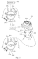
- Fig. 5 illustrates an exploded view of a pressure reducer in Fig. 2 .
- the pressure reducer 212 basically consists of a hollow cylinder 211, a cylinder core 213 and a knob 212a.
- a connection member 215 (a hollow cylinder) is used to rotatably connect the cylinder core 213 within the hollow cylinder 211.
- the connection member 215 is firmly fitted within an inner surface 212f of the hollow cylinder 211.
- the cylinder core 213 has its threaded portion 213a loosely meshed with a thread inner surface 215a of the connection member 215 such that the cylinder core 213 is rotatable relative to the connection member 215 and the hollow cylinder 211.
- a lower unthreaded portion of the cylinder core 213 is also loosely fitted within the inner surface 212f of the hollow cylinder 211, i.e. there is a gap between the inner surface 212f and the lower unthreaded portion of the cylinder core 213.
- the cylinder core 213 has two air channels (213b, 213c) whereas the hollow cylinder 211 has two pair two pairs of inlets and outlets, i.e. inlet 212c, outlet 212b, inlet 212e and outlet 212d.
- Each channel penetrates through the cylinder core 213 and has two openings on an outer surface of the cylinder core 213.
- Each air channel (213b, 213c) is employed to interconnect between each pair of inlet and outlet such that the air can be transferred through thereof.
- the knob 212a is secured to a top end 213g of the cylinder core 213 to be rotated by a user so as to enable the air channel 213b or air channel 213c to be interconnected between a corresponding pair of inlet and outlet.
- Three O-rings (217a, 217b, 217c) are respectively fitted into three grooves (213d, 213e, 213f) of the cylinder core 213.
- the O-ring 217b is located between the air channel 213b and air channel 213c.
- the air channel 213b is located between the O-ring 217a and the O-ring 217b while the air channel 213c is located between the O-ring 217b and the O-ring 217c (when three O-rings are respectively fitted into three grooves).
- Each O-ring is to airtight seal the gap between the inner surface 212f and the lower unthreaded portion of the cylinder core 213.
- Fig. 5A and Fig. 5B respectively illustrate two operation modes of the pressure reducer in Fig. 5 . These two Figures only illustrate the lower portion of the pressure reducer.
- Fig. 5A illustrates a first position of the cylinder core 213 relative to the hollow cylinder 211 where the air channel 213b interconnects between the pair of inlet 212c and outlet 212b, and the air channel 213c does not interconnect between the pair of inlet 212e and outlet 212d.
- the air channel 213c does not interconnect between the pair of inlet 212e and outlet 212d
- the pair of inlet 212e and outlet 212d are stilled gas-connected, i.e. gas can be transferred through the gap between the cylinder core 213 and the hollow cylinder 211. That is, the airflow rate through the pair of inlet 212c and outlet 212b is greater than the airflow rate through the pair of inlet 212e and outlet 212d when the cylinder core 213 is at the first position relative to the hollow cylinder 211.
- Fig. 5B illustrates a second position of the cylinder core 213 relative to the hollow cylinder 211 where the air channel 213c interconnects between the pair of inlet 212e and outlet 212d, and the air channel 213b does not interconnect between the pair of inlet 212c and outlet 212b.
- the air channel 213b does not interconnect between the pair of inlet 212c and outlet 212b
- the pair of inlet 212c and outlet 212b are stilled gas-connected through the gap between the cylinder core 213 and the hollow cylinder 211. That is, the airflow rate through the pair of inlet 212e and outlet 212d is greater than the airflow rate through the pair of inlet 212c and outlet 212b when the cylinder core 213 is at the second position relative to the hollow cylinder 211.
- the inlet 212c is connected to an upstream air distributor or regulator
- the inlet 212e and outlet 212b are both connected to the inlet 214a of the downstream air distributor 214
- the outlet 212d is to vent air out.
- the airflow rate through the pair of inlet 212c and outlet 212b is smaller than the airflow rate through the pair of inlet 212e and outlet 212d.
- the downstream airflow is flowed back through the pair of inlet 212e and outlet 212d while the pressurized air is still transferred through the pair of inlet 212c and outlet 212b.
- the air pump is serially connected with several air pressure control devices to control multiple zones of an air mattress so as to reduce needed air pressure control devices.
- two air distributors are combined and driven by a single motor such that less motors and controllers are needed to operate the air mattress.
Landscapes
- Invalid Beds And Related Equipment (AREA)
- Mattresses And Other Support Structures For Chairs And Beds (AREA)
Applications Claiming Priority (1)
| Application Number | Priority Date | Filing Date | Title |
|---|---|---|---|
| US12/561,272 US8156589B2 (en) | 2009-09-17 | 2009-09-17 | Air mattress |
Publications (3)
| Publication Number | Publication Date |
|---|---|
| EP2298136A2 true EP2298136A2 (de) | 2011-03-23 |
| EP2298136A3 EP2298136A3 (de) | 2011-10-26 |
| EP2298136B1 EP2298136B1 (de) | 2012-07-04 |
Family
ID=43273221
Family Applications (1)
| Application Number | Title | Priority Date | Filing Date |
|---|---|---|---|
| EP10173550A Not-in-force EP2298136B1 (de) | 2009-09-17 | 2010-08-20 | Luftmatratze |
Country Status (3)
| Country | Link |
|---|---|
| US (1) | US8156589B2 (de) |
| EP (1) | EP2298136B1 (de) |
| CN (1) | CN102018390A (de) |
Families Citing this family (19)
| Publication number | Priority date | Publication date | Assignee | Title |
|---|---|---|---|---|
| US8739338B2 (en) * | 2008-09-08 | 2014-06-03 | Roho, Inc. | Inflatable cushion valve and attachment apparatus |
| CN201687686U (zh) * | 2010-04-07 | 2010-12-29 | 刘应安 | 一种自动充气泵 |
| US8943627B2 (en) * | 2012-10-19 | 2015-02-03 | Jeffrey W. Wilkinson | Cushioning device and method of cushioning a body |
| US8839473B1 (en) | 2012-11-13 | 2014-09-23 | Alex Catala | Air mattress comfort adjustment system |
| US9433300B2 (en) | 2013-02-28 | 2016-09-06 | Hill-Rom Services, Inc. | Topper for a patient surface |
| US9801767B2 (en) * | 2013-03-14 | 2017-10-31 | Kap Medical, Inc. | Patient support apparatus and method |
| CN103584572A (zh) * | 2013-06-24 | 2014-02-19 | 鲁婷 | 一种智能型充气床垫 |
| US9687413B2 (en) * | 2014-02-18 | 2017-06-27 | Covidien Lp | Compression garment inflation |
| US20160091109A1 (en) * | 2014-09-30 | 2016-03-31 | Parker-Hannifin Corporation | Low torque multi-circuit control valve |
| US10888173B2 (en) * | 2016-10-28 | 2021-01-12 | Sleep Number Corporation | Air controller with vibration isolators |
| CN206368786U (zh) | 2016-12-08 | 2017-08-01 | 明达实业(厦门)有限公司 | 泵与充气产品的连接结构 |
| US10856668B2 (en) * | 2017-04-10 | 2020-12-08 | Hill-Rom Services, Inc. | Mattress overlay control system with rotary valves and graphical user interface for percussion and vibration, turn assist and microclimate management |
| CN107091219A (zh) * | 2017-06-15 | 2017-08-25 | 东莞丹蒂诗智能家居科技有限公司 | 用于软体的供气装置及其使用方法 |
| SE540929C2 (en) * | 2017-10-27 | 2018-12-27 | Care Of Sweden Ab | System and mattress for preventing pressure wounds |
| CN208669644U (zh) | 2018-05-16 | 2019-03-29 | 明达实业(厦门)有限公司 | 一种具有多通道充放气功能的泵浦 |
| EP4379217A3 (de) | 2017-11-27 | 2024-08-28 | Intex Marketing Ltd. | Manuelle aufblas- und ablasseinstellstruktur einer pumpe |
| TWI764059B (zh) * | 2019-10-31 | 2022-05-11 | 雃博股份有限公司 | 應用於病患支撐系統的配氣裝置及配氣方法 |
| US11832728B2 (en) | 2021-08-24 | 2023-12-05 | Sleep Number Corporation | Controlling vibration transmission within inflation assemblies |
| US11801175B2 (en) | 2022-01-07 | 2023-10-31 | Permobil, Inc. | Multi-position airflow control assembly for an air cushion |
Family Cites Families (17)
| Publication number | Priority date | Publication date | Assignee | Title |
|---|---|---|---|---|
| US4949412A (en) * | 1986-11-05 | 1990-08-21 | Air Plus, Inc. | Closed loop feedback air supply for air support beds |
| JPH0344187Y2 (de) * | 1987-11-10 | 1991-09-17 | ||
| US4982466A (en) | 1988-10-12 | 1991-01-08 | Leggett & Platt, Incorporated | Body support system |
| US5073999A (en) * | 1989-05-22 | 1991-12-24 | Ssi Medical Services, Inc. | Method for turning a patient with a low air loss patient support |
| GB8926213D0 (en) * | 1989-11-20 | 1990-01-10 | Pegasus Airwave Ltd | Air distributor |
| GB9117825D0 (en) * | 1991-08-16 | 1991-10-09 | Teasdale Barry C | Mattress |
| GB9616769D0 (en) * | 1996-08-09 | 1996-09-25 | Pegasus Airwave Ltd | Connector |
| CN2322479Y (zh) * | 1998-02-23 | 1999-06-09 | 杨应水 | 充水、充气床垫 |
| EP1076499B1 (de) * | 1998-05-06 | 2004-07-21 | Hill-Rom Services, Inc. | Matratze/kissenaufbau |
| TW404249U (en) * | 1998-10-09 | 2000-09-01 | Lin Mei Ting | Air-cushion bed structure with interspace exchanging and lateral positioning |
| TW404248U (en) * | 1998-10-09 | 2000-09-01 | Lin Mei Ting | Air-cushion bed structure with two-section exchangeable lateral positioning |
| CA2353208C (en) * | 2000-07-18 | 2010-12-14 | Span-America Medical Systems, Inc. | Air-powered low interface pressure support surface |
| US6698046B1 (en) * | 2001-03-26 | 2004-03-02 | Sunflower Medical, L.L.C. | Air mattress control unit |
| ES2316741T3 (es) * | 2002-02-28 | 2009-04-16 | Gaymar Industries Inc. | Dispositivo de acolchamiento auto-ajustable. |
| TWI279228B (en) * | 2003-06-18 | 2007-04-21 | Tsung-Hsi Liu | Width-adjustable air mattress bed structure |
| US7444704B2 (en) * | 2005-02-16 | 2008-11-04 | Kci Licensing, Inc. | System and method for maintaining air inflatable mattress configuration |
| TWM315087U (en) * | 2006-09-29 | 2007-07-11 | Apex Medical Corp | Air valve capable of rapidly air discharging |
-
2009
- 2009-09-17 US US12/561,272 patent/US8156589B2/en not_active Expired - Fee Related
-
2010
- 2010-08-20 EP EP10173550A patent/EP2298136B1/de not_active Not-in-force
- 2010-08-24 CN CN201010262860.4A patent/CN102018390A/zh active Pending
Non-Patent Citations (1)
| Title |
|---|
| None |
Also Published As
| Publication number | Publication date |
|---|---|
| EP2298136A3 (de) | 2011-10-26 |
| US8156589B2 (en) | 2012-04-17 |
| CN102018390A (zh) | 2011-04-20 |
| US20110061169A1 (en) | 2011-03-17 |
| EP2298136B1 (de) | 2012-07-04 |
Similar Documents
| Publication | Publication Date | Title |
|---|---|---|
| EP2298136B1 (de) | Luftmatratze | |
| US7587776B2 (en) | Dynamic therapy bed system | |
| US5189742A (en) | Pressure controlled inflatable pad apparatus | |
| US10888173B2 (en) | Air controller with vibration isolators | |
| CN101123901B (zh) | 具有多支管系统的膨胀式缓冲装置 | |
| US6820640B2 (en) | Vibratory patient support system | |
| US20150007393A1 (en) | Controller for multi-zone fluid chamber mattress system | |
| US20060143831A1 (en) | Air mattress control unit | |
| US20240180337A1 (en) | Controllable beds | |
| AU2019200856B2 (en) | Bidirectional fluid flow valve and method | |
| WO2023126883A1 (en) | Multi-chamber inflatable product with an internal pressure regulating structure | |
| US20210177680A1 (en) | Selective air segment control for a patient support mattress | |
| US8142174B2 (en) | Air pump set | |
| CN215596495U (zh) | 一种气垫气阀及充气床垫 | |
| CN210521263U (zh) | 一种带有翻身及起坐功能的防褥疮多功能床垫 | |
| CN205390921U (zh) | 一种模块式充气枕头 | |
| CN119837380A (zh) | 基于多压力传感技术的自适应调节气压型气囊床垫 | |
| IES20080930A2 (en) | A valve | |
| TWM514257U (zh) | 具有洩壓調節功能之進氣切換閥 |
Legal Events
| Date | Code | Title | Description |
|---|---|---|---|
| PUAI | Public reference made under article 153(3) epc to a published international application that has entered the european phase |
Free format text: ORIGINAL CODE: 0009012 |
|
| 17P | Request for examination filed |
Effective date: 20100820 |
|
| AK | Designated contracting states |
Kind code of ref document: A2 Designated state(s): AL AT BE BG CH CY CZ DE DK EE ES FI FR GB GR HR HU IE IS IT LI LT LU LV MC MK MT NL NO PL PT RO SE SI SK SM TR |
|
| AX | Request for extension of the european patent |
Extension state: BA ME RS |
|
| PUAL | Search report despatched |
Free format text: ORIGINAL CODE: 0009013 |
|
| AK | Designated contracting states |
Kind code of ref document: A3 Designated state(s): AL AT BE BG CH CY CZ DE DK EE ES FI FR GB GR HR HU IE IS IT LI LT LU LV MC MK MT NL NO PL PT RO SE SI SK SM TR |
|
| AX | Request for extension of the european patent |
Extension state: BA ME RS |
|
| RIC1 | Information provided on ipc code assigned before grant |
Ipc: A47C 27/10 20060101AFI20110920BHEP |
|
| GRAP | Despatch of communication of intention to grant a patent |
Free format text: ORIGINAL CODE: EPIDOSNIGR1 |
|
| RAP1 | Party data changed (applicant data changed or rights of an application transferred) |
Owner name: CAREMED SUPPLY, INC. |
|
| RIN1 | Information on inventor provided before grant (corrected) |
Inventor name: LIU, TSUNG-HSUAN |
|
| GRAS | Grant fee paid |
Free format text: ORIGINAL CODE: EPIDOSNIGR3 |
|
| GRAA | (expected) grant |
Free format text: ORIGINAL CODE: 0009210 |
|
| AK | Designated contracting states |
Kind code of ref document: B1 Designated state(s): AL AT BE BG CH CY CZ DE DK EE ES FI FR GB GR HR HU IE IS IT LI LT LU LV MC MK MT NL NO PL PT RO SE SI SK SM TR |
|
| REG | Reference to a national code |
Ref country code: GB Ref legal event code: FG4D |
|
| REG | Reference to a national code |
Ref country code: CH Ref legal event code: EP |
|
| REG | Reference to a national code |
Ref country code: AT Ref legal event code: REF Ref document number: 564782 Country of ref document: AT Kind code of ref document: T Effective date: 20120715 |
|
| REG | Reference to a national code |
Ref country code: IE Ref legal event code: FG4D |
|
| REG | Reference to a national code |
Ref country code: DE Ref legal event code: R096 Ref document number: 602010002088 Country of ref document: DE Effective date: 20120830 |
|
| REG | Reference to a national code |
Ref country code: AT Ref legal event code: MK05 Ref document number: 564782 Country of ref document: AT Kind code of ref document: T Effective date: 20120704 |
|
| REG | Reference to a national code |
Ref country code: NL Ref legal event code: VDEP Effective date: 20120704 |
|
| PG25 | Lapsed in a contracting state [announced via postgrant information from national office to epo] |
Ref country code: SI Free format text: LAPSE BECAUSE OF FAILURE TO SUBMIT A TRANSLATION OF THE DESCRIPTION OR TO PAY THE FEE WITHIN THE PRESCRIBED TIME-LIMIT Effective date: 20120704 |
|
| REG | Reference to a national code |
Ref country code: LT Ref legal event code: MG4D Effective date: 20120704 |
|
| PG25 | Lapsed in a contracting state [announced via postgrant information from national office to epo] |
Ref country code: FI Free format text: LAPSE BECAUSE OF FAILURE TO SUBMIT A TRANSLATION OF THE DESCRIPTION OR TO PAY THE FEE WITHIN THE PRESCRIBED TIME-LIMIT Effective date: 20120704 Ref country code: NO Free format text: LAPSE BECAUSE OF FAILURE TO SUBMIT A TRANSLATION OF THE DESCRIPTION OR TO PAY THE FEE WITHIN THE PRESCRIBED TIME-LIMIT Effective date: 20121004 Ref country code: BE Free format text: LAPSE BECAUSE OF FAILURE TO SUBMIT A TRANSLATION OF THE DESCRIPTION OR TO PAY THE FEE WITHIN THE PRESCRIBED TIME-LIMIT Effective date: 20120704 Ref country code: IS Free format text: LAPSE BECAUSE OF FAILURE TO SUBMIT A TRANSLATION OF THE DESCRIPTION OR TO PAY THE FEE WITHIN THE PRESCRIBED TIME-LIMIT Effective date: 20121104 Ref country code: LT Free format text: LAPSE BECAUSE OF FAILURE TO SUBMIT A TRANSLATION OF THE DESCRIPTION OR TO PAY THE FEE WITHIN THE PRESCRIBED TIME-LIMIT Effective date: 20120704 Ref country code: CY Free format text: LAPSE BECAUSE OF FAILURE TO SUBMIT A TRANSLATION OF THE DESCRIPTION OR TO PAY THE FEE WITHIN THE PRESCRIBED TIME-LIMIT Effective date: 20120704 Ref country code: AT Free format text: LAPSE BECAUSE OF FAILURE TO SUBMIT A TRANSLATION OF THE DESCRIPTION OR TO PAY THE FEE WITHIN THE PRESCRIBED TIME-LIMIT Effective date: 20120704 Ref country code: HR Free format text: LAPSE BECAUSE OF FAILURE TO SUBMIT A TRANSLATION OF THE DESCRIPTION OR TO PAY THE FEE WITHIN THE PRESCRIBED TIME-LIMIT Effective date: 20120704 |
|
| PG25 | Lapsed in a contracting state [announced via postgrant information from national office to epo] |
Ref country code: SE Free format text: LAPSE BECAUSE OF FAILURE TO SUBMIT A TRANSLATION OF THE DESCRIPTION OR TO PAY THE FEE WITHIN THE PRESCRIBED TIME-LIMIT Effective date: 20120704 Ref country code: PL Free format text: LAPSE BECAUSE OF FAILURE TO SUBMIT A TRANSLATION OF THE DESCRIPTION OR TO PAY THE FEE WITHIN THE PRESCRIBED TIME-LIMIT Effective date: 20120704 Ref country code: PT Free format text: LAPSE BECAUSE OF FAILURE TO SUBMIT A TRANSLATION OF THE DESCRIPTION OR TO PAY THE FEE WITHIN THE PRESCRIBED TIME-LIMIT Effective date: 20121105 Ref country code: GR Free format text: LAPSE BECAUSE OF FAILURE TO SUBMIT A TRANSLATION OF THE DESCRIPTION OR TO PAY THE FEE WITHIN THE PRESCRIBED TIME-LIMIT Effective date: 20121005 Ref country code: LV Free format text: LAPSE BECAUSE OF FAILURE TO SUBMIT A TRANSLATION OF THE DESCRIPTION OR TO PAY THE FEE WITHIN THE PRESCRIBED TIME-LIMIT Effective date: 20120704 |
|
| PG25 | Lapsed in a contracting state [announced via postgrant information from national office to epo] |
Ref country code: MC Free format text: LAPSE BECAUSE OF NON-PAYMENT OF DUE FEES Effective date: 20120831 Ref country code: NL Free format text: LAPSE BECAUSE OF FAILURE TO SUBMIT A TRANSLATION OF THE DESCRIPTION OR TO PAY THE FEE WITHIN THE PRESCRIBED TIME-LIMIT Effective date: 20120704 |
|
| PG25 | Lapsed in a contracting state [announced via postgrant information from national office to epo] |
Ref country code: RO Free format text: LAPSE BECAUSE OF FAILURE TO SUBMIT A TRANSLATION OF THE DESCRIPTION OR TO PAY THE FEE WITHIN THE PRESCRIBED TIME-LIMIT Effective date: 20120704 Ref country code: EE Free format text: LAPSE BECAUSE OF FAILURE TO SUBMIT A TRANSLATION OF THE DESCRIPTION OR TO PAY THE FEE WITHIN THE PRESCRIBED TIME-LIMIT Effective date: 20120704 Ref country code: ES Free format text: LAPSE BECAUSE OF FAILURE TO SUBMIT A TRANSLATION OF THE DESCRIPTION OR TO PAY THE FEE WITHIN THE PRESCRIBED TIME-LIMIT Effective date: 20121015 Ref country code: CZ Free format text: LAPSE BECAUSE OF FAILURE TO SUBMIT A TRANSLATION OF THE DESCRIPTION OR TO PAY THE FEE WITHIN THE PRESCRIBED TIME-LIMIT Effective date: 20120704 Ref country code: DK Free format text: LAPSE BECAUSE OF FAILURE TO SUBMIT A TRANSLATION OF THE DESCRIPTION OR TO PAY THE FEE WITHIN THE PRESCRIBED TIME-LIMIT Effective date: 20120704 |
|
| PLBE | No opposition filed within time limit |
Free format text: ORIGINAL CODE: 0009261 |
|
| STAA | Information on the status of an ep patent application or granted ep patent |
Free format text: STATUS: NO OPPOSITION FILED WITHIN TIME LIMIT |
|
| REG | Reference to a national code |
Ref country code: FR Ref legal event code: ST Effective date: 20130430 |
|
| REG | Reference to a national code |
Ref country code: IE Ref legal event code: MM4A |
|
| PG25 | Lapsed in a contracting state [announced via postgrant information from national office to epo] |
Ref country code: SK Free format text: LAPSE BECAUSE OF FAILURE TO SUBMIT A TRANSLATION OF THE DESCRIPTION OR TO PAY THE FEE WITHIN THE PRESCRIBED TIME-LIMIT Effective date: 20120704 Ref country code: IT Free format text: LAPSE BECAUSE OF FAILURE TO SUBMIT A TRANSLATION OF THE DESCRIPTION OR TO PAY THE FEE WITHIN THE PRESCRIBED TIME-LIMIT Effective date: 20120704 |
|
| 26N | No opposition filed |
Effective date: 20130405 |
|
| PG25 | Lapsed in a contracting state [announced via postgrant information from national office to epo] |
Ref country code: BG Free format text: LAPSE BECAUSE OF FAILURE TO SUBMIT A TRANSLATION OF THE DESCRIPTION OR TO PAY THE FEE WITHIN THE PRESCRIBED TIME-LIMIT Effective date: 20121004 Ref country code: IE Free format text: LAPSE BECAUSE OF NON-PAYMENT OF DUE FEES Effective date: 20120820 |
|
| REG | Reference to a national code |
Ref country code: DE Ref legal event code: R097 Ref document number: 602010002088 Country of ref document: DE Effective date: 20130405 |
|
| PG25 | Lapsed in a contracting state [announced via postgrant information from national office to epo] |
Ref country code: FR Free format text: LAPSE BECAUSE OF NON-PAYMENT OF DUE FEES Effective date: 20120904 |
|
| PG25 | Lapsed in a contracting state [announced via postgrant information from national office to epo] |
Ref country code: MT Free format text: LAPSE BECAUSE OF FAILURE TO SUBMIT A TRANSLATION OF THE DESCRIPTION OR TO PAY THE FEE WITHIN THE PRESCRIBED TIME-LIMIT Effective date: 20120704 Ref country code: AL Free format text: LAPSE BECAUSE OF FAILURE TO SUBMIT A TRANSLATION OF THE DESCRIPTION OR TO PAY THE FEE WITHIN THE PRESCRIBED TIME-LIMIT Effective date: 20120704 |
|
| PG25 | Lapsed in a contracting state [announced via postgrant information from national office to epo] |
Ref country code: TR Free format text: LAPSE BECAUSE OF FAILURE TO SUBMIT A TRANSLATION OF THE DESCRIPTION OR TO PAY THE FEE WITHIN THE PRESCRIBED TIME-LIMIT Effective date: 20120704 |
|
| PG25 | Lapsed in a contracting state [announced via postgrant information from national office to epo] |
Ref country code: SM Free format text: LAPSE BECAUSE OF FAILURE TO SUBMIT A TRANSLATION OF THE DESCRIPTION OR TO PAY THE FEE WITHIN THE PRESCRIBED TIME-LIMIT Effective date: 20120704 Ref country code: LU Free format text: LAPSE BECAUSE OF NON-PAYMENT OF DUE FEES Effective date: 20120820 |
|
| PG25 | Lapsed in a contracting state [announced via postgrant information from national office to epo] |
Ref country code: HU Free format text: LAPSE BECAUSE OF FAILURE TO SUBMIT A TRANSLATION OF THE DESCRIPTION OR TO PAY THE FEE WITHIN THE PRESCRIBED TIME-LIMIT Effective date: 20100820 |
|
| REG | Reference to a national code |
Ref country code: CH Ref legal event code: PL |
|
| PG25 | Lapsed in a contracting state [announced via postgrant information from national office to epo] |
Ref country code: LI Free format text: LAPSE BECAUSE OF NON-PAYMENT OF DUE FEES Effective date: 20140831 Ref country code: CH Free format text: LAPSE BECAUSE OF NON-PAYMENT OF DUE FEES Effective date: 20140831 |
|
| PG25 | Lapsed in a contracting state [announced via postgrant information from national office to epo] |
Ref country code: MK Free format text: LAPSE BECAUSE OF FAILURE TO SUBMIT A TRANSLATION OF THE DESCRIPTION OR TO PAY THE FEE WITHIN THE PRESCRIBED TIME-LIMIT Effective date: 20120704 |
|
| REG | Reference to a national code |
Ref country code: DE Ref legal event code: R082 Ref document number: 602010002088 Country of ref document: DE Representative=s name: 2K PATENT- UND RECHTSANWAELTE PARTNERSCHAFT MB, DE |
|
| PGFP | Annual fee paid to national office [announced via postgrant information from national office to epo] |
Ref country code: GB Payment date: 20200709 Year of fee payment: 11 Ref country code: DE Payment date: 20200831 Year of fee payment: 11 |
|
| REG | Reference to a national code |
Ref country code: DE Ref legal event code: R119 Ref document number: 602010002088 Country of ref document: DE |
|
| GBPC | Gb: european patent ceased through non-payment of renewal fee |
Effective date: 20210820 |
|
| PG25 | Lapsed in a contracting state [announced via postgrant information from national office to epo] |
Ref country code: GB Free format text: LAPSE BECAUSE OF NON-PAYMENT OF DUE FEES Effective date: 20210820 Ref country code: DE Free format text: LAPSE BECAUSE OF NON-PAYMENT OF DUE FEES Effective date: 20220301 |