EP2297837B1 - Magnetic pole-piece support structure - Google Patents
Magnetic pole-piece support structure Download PDFInfo
- Publication number
- EP2297837B1 EP2297837B1 EP09746045.5A EP09746045A EP2297837B1 EP 2297837 B1 EP2297837 B1 EP 2297837B1 EP 09746045 A EP09746045 A EP 09746045A EP 2297837 B1 EP2297837 B1 EP 2297837B1
- Authority
- EP
- European Patent Office
- Prior art keywords
- support structure
- magnetic
- pole piece
- pole
- magnetic support
- Prior art date
- Legal status (The legal status is an assumption and is not a legal conclusion. Google has not performed a legal analysis and makes no representation as to the accuracy of the status listed.)
- Active
Links
Images


Classifications
-
- H—ELECTRICITY
- H02—GENERATION; CONVERSION OR DISTRIBUTION OF ELECTRIC POWER
- H02K—DYNAMO-ELECTRIC MACHINES
- H02K1/00—Details of the magnetic circuit
- H02K1/06—Details of the magnetic circuit characterised by the shape, form or construction
- H02K1/08—Salient poles
-
- H—ELECTRICITY
- H02—GENERATION; CONVERSION OR DISTRIBUTION OF ELECTRIC POWER
- H02K—DYNAMO-ELECTRIC MACHINES
- H02K51/00—Dynamo-electric gears, i.e. dynamo-electric means for transmitting mechanical power from a driving shaft to a driven shaft and comprising structurally interrelated motor and generator parts
-
- H—ELECTRICITY
- H02—GENERATION; CONVERSION OR DISTRIBUTION OF ELECTRIC POWER
- H02K—DYNAMO-ELECTRIC MACHINES
- H02K7/00—Arrangements for handling mechanical energy structurally associated with dynamo-electric machines, e.g. structural association with mechanical driving motors or auxiliary dynamo-electric machines
- H02K7/10—Structural association with clutches, brakes, gears, pulleys or mechanical starters
- H02K7/11—Structural association with clutches, brakes, gears, pulleys or mechanical starters with dynamo-electric clutches
-
- H—ELECTRICITY
- H02—GENERATION; CONVERSION OR DISTRIBUTION OF ELECTRIC POWER
- H02K—DYNAMO-ELECTRIC MACHINES
- H02K1/00—Details of the magnetic circuit
- H02K1/02—Details of the magnetic circuit characterised by the magnetic material
-
- H—ELECTRICITY
- H02—GENERATION; CONVERSION OR DISTRIBUTION OF ELECTRIC POWER
- H02K—DYNAMO-ELECTRIC MACHINES
- H02K49/00—Dynamo-electric clutches; Dynamo-electric brakes
- H02K49/10—Dynamo-electric clutches; Dynamo-electric brakes of the permanent-magnet type
- H02K49/102—Magnetic gearings, i.e. assembly of gears, linear or rotary, by which motion is magnetically transferred without physical contact
Definitions
- the present invention relates, in general, to novel designs of magnetic pole-piece support structures used for magnetic gears and machines with integrated magnetic gearing such as the so-called pseudo direct drive machines.
- Magnetic gears offer significant advantages compared with mechanical gears, such as no contacting surfaces, removing the need for lubrication, and hence reduced maintenance and improved reliability, inherent overload protection (as the gear harmlessly pole slips on over torque), and physical isolation between the input and output shafts. Providing the iron losses (e.g. due to eddy currents in the pole pieces) can be minimised, the magnetic gear is also highly efficient.
- a rotary magnetic gear 100 is provided by a first or inner rotor 102, a second or outer rotor 104 and a number of pole pieces 106.
- the first rotor 102 comprises a support 108 bearing a respective first number of permanent magnets 110.
- the first rotor 102 comprises 8 permanent magnets or 4 pole-pairs arranged to produce a spatially varying magnetic field.
- the second rotor 104 comprises a support 112 bearing a respective second number of permanent magnets 114.
- the second rotor 104 illustrated comprises 46 permanent magnets or 23 pole-pairs arranged to produce a spatially varying field.
- the first and second numbers of permanent magnets are different. Accordingly, in the absence of the pole-pieces there will be little or no useful magnetic coupling or interaction between the permanents magnets 112 and 114 and there will be no net torque such that rotation of one rotor will not cause continuous rotation of the other rotor.
- the pole pieces 106 are used to allow the fields of the permanent magnets 110 and 114 to couple together and transmit torque.
- the pole pieces 106 modulate the magnetic fields of the permanent magnets 110 and 114 so they interact to the extent that rotation of one rotor will induce rotation of the other rotor in a geared manner, i.e. the speed will be increased or decreased and the torque will be decreased or increased.
- EP1353436A2 discloses an electrical machine comprising a combined magnetic gearbox and electrical generator.
- a first set of permanent magnets are arranged on a rotor to produce a spatially variable first magnetic field.
- a second set of permanent magnets are arranged on a rotor, stationary pole pieces are positioned between the first set of permanent magnets and the second set of permanent magnets to interfere with the first magnetic field. Rotation of the rotor relative to the pole pieces produces a second magnetic field which rotates the second set of permanent magnets.
- a stator has windings to transduce a changing second magnetic field produced by the rotation of the second set of permanent magnets into an electrical voltage.
- EP1528659A2 discloses a rotary electric machine includes inner and outer rotors each including permanent magnets, and a stator including stator coils, disposed between the inner and outer rotors.
- the inner rotor further includes outer surface portions serving as a yoke portion of an outer magnetic circuit for magnetic flux synchronous with the outer rotor, and the outer rotor further includes outer portions each located on an outer side of one of the outer permanent magnet, and arranged to serve as a yoke portion of an inner magnetic circuit for magnetic flux synchronous with the inner rotor.
- JP2003299327A discloses a rotating electric machine having an inner rotor and an outer rotor having a plurality of magnets in the circumferential direction coaxially positioned with one stator between and driven by a combined current supplied to coils of the stator.
- the inner high speed rotor is usually rotating, connected to the high speed input/output shaft and one of either the pole pieces or outer magnets can be the other rotor, (connected to the low speed shaft), with the other held static.
- These two arrangements offer a different gear ratio (similar in operation to a planetary gear).
- the pole pieces are generally the low speed rotating element, with one set of magnets held stationary on the stator.
- an electrical motor/generator combined with a magnetic gear can be provided.
- the pole-pieces included in the arrangement can be fixed as a stator or rotatable as a rotor themselves.
- An example of such an arrangement is provided in Figure 2 , which shows the principle of operation of such an electrical machine 200.
- the electrical machine 200 comprises a first or inner rotor 202 having a support 204 bearing a first plurality of permanent magnets 206.
- permanent magnets having 10 poles are used.
- embodiments are not limited to using such a number of permanent magnets. Embodiments can be realised that use some other number of permanent magnets.
- the electrical machine 200 comprises a second rotor 208 in the form of a plurality of ferromagnetic pole pieces.
- the pole pieces 208 are arranged to magnetically couple the permanent magnets 206 of the first/inner rotor 202 to a plurality of permanent magnets 210 that are fixed to a periphery of the wound stator in the region of the pole shoes 212 of respective teeth 214 thereby forming a stator 216.
- 60 permanent magnets are fixed to the periphery of the wound stator 212.
- the embodiment comprises 15 teeth 214 with the respective periphery of the wound stator 212. It will be appreciated that embodiments are not limited to such a number of permanent magnets and teeth. Embodiments comprising some other number of permanent magnets and teeth can be realised.
- the pole pieces 208 form a rotatable array of pole pieces 208. That is, they form a rotor.
- the inner rotor 202 is rotatable.
- the teeth 214 and associated permanent magnets 210 are fixed.
- the coupling between the permanent magnets 206 and the permanent magnets 210 is realised using the rotatable pole pieces 208.
- Associated with the stator 216 is a plurality of 3-phase windings 1, 1', 2, 2' and 3, 3'.
- the 3- phase windings, and associated currents, are arranged to create magnetic fields that to couple with or form magnetic circuits with the first or fundamental harmonic of the permanent magnets 206 associated with the inner rotor 202.
- the pole pieces 208 are usually connected to an end plate to transmit the torque to a central shaft.
- any multi-phase winding can be used such as a 5-phase winding.
- pole pieces are subject to large mechanical loads as:
- annulus structure can have high strength this is not the case here due to the requirement for alternating non-magnetic and magnetic regions requiring a combination of different materials.
- This problem is exacerbated by the fact that magnetic and therefore typically ferromagnetic segments are usually a laminated structure (typically stacks of laminates of Silicon Iron 0.2 to 0.65mm thick) in order to prevent/reduce eddy currents which would be induced by changing magnetic fields which lead to losses and reduced efficiency.
- the lamination stacks preferably should not be welded together as this creates an electrical short circuit allowing induced currents to flow.
- the pole pieces could be manufactured from soft magnetic composite (SMC) which is a hot pressed part with good magnetic properties but a low electrical resistivity, but is mechanically inferior to solid steels. Therefore these components (either laminated or SMC) do not have high integral strength.
- SMC soft magnetic composite
- the non-magnetic regions in-between the pole-pieces are preferably non-conducting, precluding non-magnetic steels and other metallic structures, again to prevent eddy currents and their associated losses. Therefore, the intermediate regions are preferably a non-conducting, non-magnetic material such as a plastic, carbon-fibre or cast epoxy.
- pole pieces it is also possible to attach the pole pieces to an end-cap to take the torque to the output/input shaft or case although such an arrangement becomes more problematic as the machine (axial) length increases. If the pole pieces are connected to the shaft at one end they present a simple cantilever and will bend in the circumferential direction when torque is applied, with a maximum deflection at the end of the pole-piece section. The pole-pieces may be connected at either end at the deflection will be maximum in the centre of the machine. As the machine axial length increases the distance between potential anchor points at end plates increases, leading to the potential for larger deflections.
- pole-pieces could be placed under compression to pre-load the stacks (to reduce deflection due to the circumferential acting torque and radial magnetic pull).
- these loads increase the compressive forces will become excessive and may damage the insulation between lamination stacks (leading to electrical breakdown and localised hotspots, and ultimately a serious failure).
- a pole piece support as claimed in claim 1.
- the pole piece support is suitable for use in a magnetic drive system, magnetic gear and electrical machine.
- a magnetic drive system comprising three members, a first and second of which form an input member and an output member each arranged to rotate relative to the third member, wherein two of the members have respective sets of permanent magnets, the two sets having different numbers of magnetic poles, and the other of the members comprising a pole piece support as claimed in any one of the independent or dependent claims.
- a schematic diagram of shaped pole pieces and shaped support structures comprise a first shaped pole piece 300 keyed into a first support structure 302.
- the first shaped pole piece 300 comprises an insert to receive an extension from the first support structure 302.
- Magnetic modelling can identify how much the first pole piece 300 can be shaped with recesses or extensions to key into the first support structure 302 without significantly affecting the magnetic performance of the system.
- the first pole piece 300 and support structure 302 have opposing male/female parts.
- FIG. 36 Further examples include a second shaped pole piece 304 keyed into a second support structure 306.
- the second pole piece 304 comprises a male part inserted into a female part of the second support structure 306.
- a third pole piece 308 comprises an insert to receive a third support structure 310 shaped as a strengthening bar.
- a fourth pole piece 312 comprises a series of extensions and recesses along its edge which correspondingly mate with a series of opposing extensions and recesses along the edge of a fourth support structure 314.
- the support structures described in relation to Figure 3 are non-magnetic and manufactured from a composite structure such as a carbon fibre or glass fibre.
- the support structure can be selected from a range of engineering plastics known in the art. Such an engineering plastic can be PEEK.
- the support structure is a carbon-fibre pultrusion. Carbon fibre pultrusions are manufactured by drawing carbon fibres and appropriate resin through a die to offer a net shape part. The carbon fibres and/or filaments lay parallel to the length of the support structure giving significant strength. Alternatively, a cross-weave layered carbon fibre structure can be employed.
- a pole piece 400 comprises an elongate body 402 comprising an insert 404 along its length.
- a carbon fibre pultrusion support structure 406 comprises an extension 408 for insertion within the insert 404 of the pole piece 400.
- An aperture 410 is provided within the support structure 406 for receiving a strengthening bar (not shown in Figure 4 ).
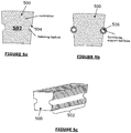
- Figure 5a illustrates a first embodiment of the present invention where a pole piece 500 is provided with laminations 502.
- the laminations 502 are provided with cut-outs 504 on the outer edges of the laminations 502. This has the advantage of having negligible effect on the magnetic flux paths.
- a supporting bar 506 or the like is provided along the cut-outs 504 to reinforce the laminations 502.
- Figure 5c is a perspective view of a pole-piece of Figure 5a .
- the pole piece (which as discussed above may be a laminated stack) can be bonded to the non-magnetic support structures using an appropriate adhesive.
- the adhesive can serve as a gap-filler as the surface of the laminated stack is generally not smooth.
- the adhesive can be a sacrificial adhesive and so not contribute significantly to the overall strength of the support structure.
- the adhesive can contribute to the load bearing strength of a pole piece support structure and so be non-sacrificial. In such an embodiment, should the adhesive fail, then the magnetic pole piece is retained by the support structure and does not drop out.
- the adhesive is applied at the contact area of the non-magnetic support structure and an outer surface of a magnetic pole-piece.
- the adhesive is present in a thickness of 0.05mm to 0.5mm, more preferably 0.1mm to 0.3mm, very preferably around 0.2mm.
- the non-magnetic support structure and pole pieces are carried by end rings to transmit a torque to an input/output shaft.
- the support structure can be keyed into the end ring to aid location and to transmit the torque.
- the end ring is metallic such as steel although alternative materials such as a carbon fibre or glass fibre composites can be employed.
- the arrangement of the support structure and pole pieces being carried by end ring(s) may be insufficient and additional location, rigidity and torque capability can be introduced by the use of a tensioned element which passes through the first set of support structures, as shown in figure 6a and can be anchored to the end rings.
- This tensioned element will typically be a carbon-fibre rod (which have excellent tensile strength) and may also be manufactured using a pultrusion process.
- a tensioning bar 600 is inserted within a non-magnetic support structure 602. Technologies are well known for terminating the support bar 600 which allows standard mechanical fixtures to be employed such as a threaded bolts or eyelets. Alternatively support bar 600 can be terminated through splicing techniques (in which the ends are splayed out or moulded over a boss feature (or looped similar to eyelet terminations in rope).
- the support bar 600 can be put under significant tension without necessarily compressing the lamination stacks as the compression is borne by the support bar 600.
- Pre-tensioning the support bar 600 significantly reduces bending due to the two major forces acting on them due to the main drive torque and the magnetic radial pull.
- the support bar 600 can manufactured from a metallic material such as high tensile steel.
- the majority (or all of these rods) must be isolated from any steel structure (e.g. steel end ring) at at least one of their ends to prevent circulating currents being induced. This may be achieved using insulated collars/sleeves etc between the rods and end plate.
- a number of these rods may be connected directly to a conducting end-ring at both ends without causing circulating currents (as they enclose an even number of north and south poles and the net flux linking them is zero).
- a high strength, non-conducting end ring was employed e.g. carbon fibre ring, the circuit would not be closed.
- an intermediate support structure 700 are provided by a ring structure.
- the ring structure is not necessarily fixed to a shaft (to enable the high speed rotor to be located concentrically within the pole-piece rotor.
- These intermediate rings could be manufactured from steel, but would then potentially have eddy currents induced in it leading to higher losses. Therefore carbon-fibre composite or glass fibre rings may be employed.
- This ring may have an array of holes for the tensioned support bars 600 to pass through (restricting their radial and circumferential movement) as shown in figure 7 .
- the rings may also have a lip or rim to provide location for the pole pieces 604 and support structures 606. In larger machines it may be advantageous to manufacture these rings from smaller segments.
- a part section of a final assembly of a pole piece rotor 800 comprises a first end cap 802 connected to one end of a pole piece support structure comprising pole pieces 804, an array of non-magnetic support structures 806 retained by said tensioning bars 600 and intermediate support structure 808 and at another end a second end cap 810.
Description
- The present invention relates, in general, to novel designs of magnetic pole-piece support structures used for magnetic gears and machines with integrated magnetic gearing such as the so-called pseudo direct drive machines.
- Magnetic gears offer significant advantages compared with mechanical gears, such as no contacting surfaces, removing the need for lubrication, and hence reduced maintenance and improved reliability, inherent overload protection (as the gear harmlessly pole slips on over torque), and physical isolation between the input and output shafts. Providing the iron losses (e.g. due to eddy currents in the pole pieces) can be minimised, the magnetic gear is also highly efficient.
- A magnetic gear topology which combines a high torque transmission capability and high efficiency is disclosed in
WO 2007/125284 , the contents of which are incorporated herein in their entirety. - Referring to
Figure 1 ofWO 2007/125284 , a rotarymagnetic gear 100 is provided by a first orinner rotor 102, a second orouter rotor 104 and a number ofpole pieces 106. Thefirst rotor 102 comprises asupport 108 bearing a respective first number ofpermanent magnets 110. In the illustrated magnetic gear ofFigure 1 , thefirst rotor 102 comprises 8 permanent magnets or 4 pole-pairs arranged to produce a spatially varying magnetic field. Thesecond rotor 104 comprises asupport 112 bearing a respective second number ofpermanent magnets 114. Thesecond rotor 104 illustrated comprises 46 permanent magnets or 23 pole-pairs arranged to produce a spatially varying field. The first and second numbers of permanent magnets are different. Accordingly, in the absence of the pole-pieces there will be little or no useful magnetic coupling or interaction between thepermanents magnets - The
pole pieces 106 are used to allow the fields of thepermanent magnets pole pieces 106 modulate the magnetic fields of thepermanent magnets -
EP1353436A2 discloses an electrical machine comprising a combined magnetic gearbox and electrical generator. A first set of permanent magnets are arranged on a rotor to produce a spatially variable first magnetic field. A second set of permanent magnets are arranged on a rotor, stationary pole pieces are positioned between the first set of permanent magnets and the second set of permanent magnets to interfere with the first magnetic field. Rotation of the rotor relative to the pole pieces produces a second magnetic field which rotates the second set of permanent magnets. A stator has windings to transduce a changing second magnetic field produced by the rotation of the second set of permanent magnets into an electrical voltage. -
EP1528659A2 discloses a rotary electric machine includes inner and outer rotors each including permanent magnets, and a stator including stator coils, disposed between the inner and outer rotors. The inner rotor further includes outer surface portions serving as a yoke portion of an outer magnetic circuit for magnetic flux synchronous with the outer rotor, and the outer rotor further includes outer portions each located on an outer side of one of the outer permanent magnet, and arranged to serve as a yoke portion of an inner magnetic circuit for magnetic flux synchronous with the inner rotor. -
JP2003299327A - Within a gear, two of the three elements are rotating and one is held static. The inner high speed rotor is usually rotating, connected to the high speed input/output shaft and one of either the pole pieces or outer magnets can be the other rotor, (connected to the low speed shaft), with the other held static. These two arrangements offer a different gear ratio (similar in operation to a planetary gear). However, in a pseudo direct machine, in which the gear has been integrated into an electrical machine, the pole pieces are generally the low speed rotating element, with one set of magnets held stationary on the stator.
- One skilled in the art understands how to select and design the
pole pieces 106, given the first 110 and second 114 permanent magnets, to achieve the necessary magnetic circuit or coupling such that gearing between the first 102 and second 104 rotors results as can be appreciated from, for example, K. Atallah, D. Howe, "A novel high-performance magnetic gear", IEEE Transactions on Magnetics, Vol. 37, No. 4, pp. 2844-2846, 2001 and K. Atallah, S. D. Calverley, D. Howe, "Design, analysis and realisation of a high performance magnetic gear", IEE Proceedings - Electric Power Applications, Vol. 151, pp. 135-143, 2004, which are incorporated herein by reference in their entirety. - In alternative embodiments, an electrical motor/generator combined with a magnetic gear can be provided. Additionally, the pole-pieces included in the arrangement can be fixed as a stator or rotatable as a rotor themselves. An example of such an arrangement is provided in
Figure 2 , which shows the principle of operation of such anelectrical machine 200. - The
electrical machine 200 comprises a first orinner rotor 202 having a support 204 bearing a first plurality ofpermanent magnets 206. In the embodiment shown, permanent magnets having 10 poles are used. However, embodiments are not limited to using such a number of permanent magnets. Embodiments can be realised that use some other number of permanent magnets. Theelectrical machine 200 comprises asecond rotor 208 in the form of a plurality of ferromagnetic pole pieces. Thepole pieces 208 are arranged to magnetically couple thepermanent magnets 206 of the first/inner rotor 202 to a plurality ofpermanent magnets 210 that are fixed to a periphery of the wound stator in the region of thepole shoes 212 ofrespective teeth 214 thereby forming astator 216. In the embodiment shown, 60 permanent magnets are fixed to the periphery of thewound stator 212. The embodiment comprises 15teeth 214 with the respective periphery of thewound stator 212. It will be appreciated that embodiments are not limited to such a number of permanent magnets and teeth. Embodiments comprising some other number of permanent magnets and teeth can be realised. - The
pole pieces 208 form a rotatable array ofpole pieces 208. That is, they form a rotor. Theinner rotor 202 is rotatable. Theteeth 214 and associatedpermanent magnets 210 are fixed. The coupling between thepermanent magnets 206 and thepermanent magnets 210 is realised using therotatable pole pieces 208. Associated with thestator 216 is a plurality of 3-phase windings permanent magnets 206 associated with theinner rotor 202. Thepole pieces 208 are usually connected to an end plate to transmit the torque to a central shaft. Although in the present case a plurality of 3-phase windings are associated with thestator 216, in general any multi-phase winding can be used such as a 5-phase winding. - During operation the pole pieces are subject to large mechanical loads as:
- 1) The output/input mechanical torque (or reaction torque) of the gear or machine acts circumferentially on the pole pieces (that is, tangential to the direction of motion);
- 2) A radial magnetic pull due to the permanent magnet field which is cyclic in nature due to the different speeds of the magnet rotor and pole pieces;
- 3) Each pole piece can be subject to a torsional force or torque about its own axis as it tries to align itself with the complex magnetic field.
- Although an annulus structure can have high strength this is not the case here due to the requirement for alternating non-magnetic and magnetic regions requiring a combination of different materials. This problem is exacerbated by the fact that magnetic and therefore typically ferromagnetic segments are usually a laminated structure (typically stacks of laminates of Silicon Iron 0.2 to 0.65mm thick) in order to prevent/reduce eddy currents which would be induced by changing magnetic fields which lead to losses and reduced efficiency. The lamination stacks preferably should not be welded together as this creates an electrical short circuit allowing induced currents to flow. Alternatively the pole pieces could be manufactured from soft magnetic composite (SMC) which is a hot pressed part with good magnetic properties but a low electrical resistivity, but is mechanically inferior to solid steels. Therefore these components (either laminated or SMC) do not have high integral strength.
- The non-magnetic regions in-between the pole-pieces are preferably non-conducting, precluding non-magnetic steels and other metallic structures, again to prevent eddy currents and their associated losses. Therefore, the intermediate regions are preferably a non-conducting, non-magnetic material such as a plastic, carbon-fibre or cast epoxy.
- Previous examples of gears and magnetically geared machines have used pole-pieces moulded or cast into an epoxy substrate. However, fully enclosing the pole-pieces with material radially above and below the pole-piece (to radially contain the pole piece against the high magnetic forces) can have some drawbacks depending upon their application. For example, the magnetic airgap is extended which can reduce the performance of the gear/machine; and the cooling of the pole-pieces required to remove the heat due to hysteresis loss and eddy currents is significantly reduced. Ideally the faces of the pole pieces should be exposed to ensure they are adjacent a flow of cooling air.
- Approaches to pole-piece rotor manufacture of this nature were disclosed in one of the applicant's previous patent applications
GB0800463.2 - It is also possible to attach the pole pieces to an end-cap to take the torque to the output/input shaft or case although such an arrangement becomes more problematic as the machine (axial) length increases. If the pole pieces are connected to the shaft at one end they present a simple cantilever and will bend in the circumferential direction when torque is applied, with a maximum deflection at the end of the pole-piece section. The pole-pieces may be connected at either end at the deflection will be maximum in the centre of the machine. As the machine axial length increases the distance between potential anchor points at end plates increases, leading to the potential for larger deflections.
- The pole-pieces could be placed under compression to pre-load the stacks (to reduce deflection due to the circumferential acting torque and radial magnetic pull). However, as these loads increase the compressive forces will become excessive and may damage the insulation between lamination stacks (leading to electrical breakdown and localised hotspots, and ultimately a serious failure). According to a first aspect of the present invention, there is provided a pole piece support as claimed in
claim 1. - Preferred embodiments are described in the dependent claims.
- The pole piece support is suitable for use in a magnetic drive system, magnetic gear and electrical machine. Preferably, a magnetic drive system comprising three members, a first and second of which form an input member and an output member each arranged to rotate relative to the third member, wherein two of the members have respective sets of permanent magnets, the two sets having different numbers of magnetic poles, and the other of the members comprising a pole piece support as claimed in any one of the independent or dependent claims.
- Embodiments of the invention will now be described, by way of example only, and with reference to the accompanying drawings in which:
-
Figure 1 is a schematic diagram of a rotary magnetic gear according to the prior art; -
Figure 2 is a schematic diagram of a combined electrical machine and magnetic gear according to the prior art; -
Figure 3 is a schematic diagram of shaped pole pieces and shaped support structures according to a first embodiment of the invention; -
Figure 4a is a schematic diagram of a pole piece profile andFigure 4b is a schematic diagram of a support structure profile corresponding to the pole piece profile ofFigure 4b according to the first embodiment of the invention; -
Figures 5a to 5c are schematic diagrams of a pole piece laminate stack shown with and without an adjacent support structure according to the first embodiment of the present invention; -
Figure 6a is a schematic diagram of a pole piece support structure without pole pieces in place andFigure 6b is a schematic diagram of a pole piece support structure with pole pieces in place according to the first embodiment of the present invention; -
Figure 7 is a schematic diagram of a pole piece rotor construction without pole pieces shown according to a second embodiment of the present invention; and -
Figure 8 is a schematic diagram of a pole piece rotor construction including pole pieces and appropriate end caps. - With reference to
Figure 3 , a schematic diagram of shaped pole pieces and shaped support structures according to a first embodiment of the invention comprise a first shapedpole piece 300 keyed into a first support structure 302. The first shapedpole piece 300 comprises an insert to receive an extension from the first support structure 302. Magnetic modelling can identify how much thefirst pole piece 300 can be shaped with recesses or extensions to key into the first support structure 302 without significantly affecting the magnetic performance of the system. Thefirst pole piece 300 and support structure 302 have opposing male/female parts. - Further examples include a second shaped
pole piece 304 keyed into asecond support structure 306. Thesecond pole piece 304 comprises a male part inserted into a female part of thesecond support structure 306. Athird pole piece 308 comprises an insert to receive athird support structure 310 shaped as a strengthening bar. Afourth pole piece 312 comprises a series of extensions and recesses along its edge which correspondingly mate with a series of opposing extensions and recesses along the edge of afourth support structure 314. - The support structures described in relation to
Figure 3 are non-magnetic and manufactured from a composite structure such as a carbon fibre or glass fibre. Alternatively, the support structure can be selected from a range of engineering plastics known in the art. Such an engineering plastic can be PEEK. In the particular specific description, the support structure is a carbon-fibre pultrusion. Carbon fibre pultrusions are manufactured by drawing carbon fibres and appropriate resin through a die to offer a net shape part. The carbon fibres and/or filaments lay parallel to the length of the support structure giving significant strength. Alternatively, a cross-weave layered carbon fibre structure can be employed. - As best seen in
Figure 4a , apole piece 400 comprises anelongate body 402 comprising aninsert 404 along its length. A carbon fibrepultrusion support structure 406 comprises anextension 408 for insertion within theinsert 404 of thepole piece 400. Anaperture 410 is provided within thesupport structure 406 for receiving a strengthening bar (not shown inFigure 4 ). - A similar arrangement to that described in
Figure 3 is described with reference toFigures 5a to 5c. Figure 5a illustrates a first embodiment of the present invention where apole piece 500 is provided withlaminations 502. Thelaminations 502 are provided with cut-outs 504 on the outer edges of thelaminations 502. This has the advantage of having negligible effect on the magnetic flux paths. As best seen inFigure 5b , a supportingbar 506 or the like is provided along the cut-outs 504 to reinforce thelaminations 502.Figure 5c is a perspective view of a pole-piece ofFigure 5a . - In the first embodiment of the present invention, the pole piece (which as discussed above may be a laminated stack) can be bonded to the non-magnetic support structures using an appropriate adhesive. The adhesive can serve as a gap-filler as the surface of the laminated stack is generally not smooth. The adhesive can be a sacrificial adhesive and so not contribute significantly to the overall strength of the support structure. Alternatively, the adhesive can contribute to the load bearing strength of a pole piece support structure and so be non-sacrificial. In such an embodiment, should the adhesive fail, then the magnetic pole piece is retained by the support structure and does not drop out.
- In such an arrangement the adhesive is applied at the contact area of the non-magnetic support structure and an outer surface of a magnetic pole-piece.
- Perferably, the adhesive is present in a thickness of 0.05mm to 0.5mm, more preferably 0.1mm to 0.3mm, very preferably around 0.2mm.
- According to the first embodiment of the present invention, the non-magnetic support structure and pole pieces are carried by end rings to transmit a torque to an input/output shaft. The support structure can be keyed into the end ring to aid location and to transmit the torque. Generally the end ring is metallic such as steel although alternative materials such as a carbon fibre or glass fibre composites can be employed.
- However, in many applications the arrangement of the support structure and pole pieces being carried by end ring(s) may be insufficient and additional location, rigidity and torque capability can be introduced by the use of a tensioned element which passes through the first set of support structures, as shown in
figure 6a and can be anchored to the end rings. This tensioned element will typically be a carbon-fibre rod (which have excellent tensile strength) and may also be manufactured using a pultrusion process. - Therefore referring to
Figure 6a , atensioning bar 600 is inserted within anon-magnetic support structure 602. Technologies are well known for terminating thesupport bar 600 which allows standard mechanical fixtures to be employed such as a threaded bolts or eyelets. Alternativelysupport bar 600 can be terminated through splicing techniques (in which the ends are splayed out or moulded over a boss feature (or looped similar to eyelet terminations in rope). - The
support bar 600 can be put under significant tension without necessarily compressing the lamination stacks as the compression is borne by thesupport bar 600. - Pre-tensioning the
support bar 600 significantly reduces bending due to the two major forces acting on them due to the main drive torque and the magnetic radial pull. - Alternatively the
support bar 600 can manufactured from a metallic material such as high tensile steel. The majority (or all of these rods) must be isolated from any steel structure (e.g. steel end ring) at at least one of their ends to prevent circulating currents being induced. This may be achieved using insulated collars/sleeves etc between the rods and end plate. However, by careful design a number of these rods may be connected directly to a conducting end-ring at both ends without causing circulating currents (as they enclose an even number of north and south poles and the net flux linking them is zero). Alternatively if a high strength, non-conducting end ring was employed e.g. carbon fibre ring, the circuit would not be closed. - With reference to
Figure 6b , an array of pole-pieces 604 are now rigidly mounted within the non-magnetic support structures 606: - 1) The main drive torque acting on the pole-
piece 604 also acts upon thesupport structures 606 between each pole-piece 604 and prevents bending of the structure circumferentially. Deflection of these are minimised by the tensioned support bars 600 through thesupport structures 606. - 2) The
support structures 606 prevent radial movement of thepole pieces 604 when provided as laminated stacks (as it has a keyed feature) and deflections are prevented due to the tensioned support bars 600. - 3) Torsion of the pole-
pieces 604 due to magnetic forces along their own axis is also prevented by thesupport structures 606. - As the torque requirements increase it may be necessary to increase the axial length of the machine rotor and hence the pole pieces. The distance between rigid anchor points for the tensioned support bars 600 and the
support structures 606 andpole pieces 604 is then extended potentially allowing an increase in deflection. To overcome the increase in deflection, anintermediate support structure 700 are provided by a ring structure. The ring structure is not necessarily fixed to a shaft (to enable the high speed rotor to be located concentrically within the pole-piece rotor. These intermediate rings could be manufactured from steel, but would then potentially have eddy currents induced in it leading to higher losses. Therefore carbon-fibre composite or glass fibre rings may be employed. This ring may have an array of holes for the tensioned support bars 600 to pass through (restricting their radial and circumferential movement) as shown infigure 7 . The rings may also have a lip or rim to provide location for thepole pieces 604 andsupport structures 606. In larger machines it may be advantageous to manufacture these rings from smaller segments. - Referring to
Figure 8 , a part section of a final assembly of apole piece rotor 800 comprises a first end cap 802 connected to one end of a pole piece support structure comprisingpole pieces 804, an array ofnon-magnetic support structures 806 retained by said tensioning bars 600 andintermediate support structure 808 and at another end asecond end cap 810. - No doubt many other effective alternatives will occur to the skilled person. It will be understood that the invention is not limited to the described embodiments and encompasses modifications apparent to those skilled in the art lying within the scope of the claims appended hereto.
Claims (12)
- A pole piece support structure for a magnetic gear or an electrical machine comprising an integrated magnetic gear, the pole piece support structure comprising:a substantially cylindrical frame having a central axis, the frame having a spaced array of non-magnetic support structures (302, 306, 310, 406, 602, 606, 806) extending axially, each non-magnetic support structure comprises an aperture (410) having a stiffening bar (600) extending therethrough, the stiffening bar being held under tension;a magnetic pole piece (300, 304, 308, 400, 500, 604, 804) disposed between at least a pair of adjacent non-magnetic support structures (302, 306, 310, 602, 606, 806), the magnetic pole piece (300, 304, 308, 400, 500, 604, 804) being supported along at least a portion of its body by the adjacent non-magnetic support structures, the body of the magnetic pole piece comprising a retaining feature and the retaining feature mating with a corresponding retaining feature in the body of each of the non-magnetic support structures, an end support (802, 810) at each axial end; andan intermediate support structure (700, 808) forming a ring structure at least partially circumferentially around the frame, the intermediate support structure (700, 808) having an array of holes for the stiffening bars (600) to pass through, the intermediate support structure (700, 808) being provided between axial ends of the adjacent non-magnetic support structures (602, 606, 806),wherein the substantially cylindrical frame, the intermediate support structure (700, 808) and the end supports (802, 810) form a grid-like structure to axially, radially and circumferentially retain the magnetic pole pieces (402, 604, 804).
- A pole piece support structure as claimed in claim 1, wherein the retaining feature is a male or female part that mates with a corresponding male or female part formed in the body of the non-magnetic support structure.
- A pole piece support structure as claimed in claim 1, wherein the non-magnetic support structure is accommodated within a cut-out retaining feature in the body of the magnetic pole piece (604, 804).
- A pole piece support structure as claimed in claim 3, wherein the non-magnetic support structure is a substantially cylindrical bar.
- A pole piece support structure as claimed in claim 1, wherein the magnetic pole piece (604, 804) is accommodated within a cut-out retaining feature in the body of the non-magnetic support structure.
- A pole piece support structure as claimed in any one of the preceding claims, wherein the ring structure comprises an array of apertures through which the non-magnetic support structures are retained.
- A pole piece support structure as claimed in any one of the preceding claims, wherein the intermediate structure comprises a face having a lip or a rim for locating a pole piece or a non-magnetic support structure.
- A pole piece support structure as claimed in any one of the preceding claims, wherein the non-magnetic support structure is formed by a pultrusion process.
- A pole piece support structure as claimed in any one of the preceding claims, wherein the non-magnetic support structure comprises a carbon fibre pultrusion manufactured by drawing carbon fibres and appropriate resin through a die to offer a net shape part.
- A pole piece support structure as claimed in claim 8 or claim 9, wherein the pultruded non-magnetic support structure is shaped to key into adjacent magnetic pole pieces (604, 804).
- A pole piece support structure as claimed in any preceding claim, wherein a gap is provided between the magnetic pole piece (604, 804) and the end supports.
- A pole piece support structure as claimed in any preceding claim, wherein an adhesive is applied at a contact area where the magnetic pole piece (604, 804) is supported along at least a portion of its body by the adjacent non-magnetic support structures.
Applications Claiming Priority (3)
| Application Number | Priority Date | Filing Date | Title |
|---|---|---|---|
| GBGB0808524.3A GB0808524D0 (en) | 2008-05-12 | 2008-05-12 | Magnetic pole-piece structure |
| GBGB0902370.6A GB0902370D0 (en) | 2008-05-12 | 2009-02-13 | Magnetic pole-piece support |
| PCT/GB2009/001178 WO2009138728A2 (en) | 2008-05-12 | 2009-05-12 | Magnetic pole-piece support |
Publications (2)
| Publication Number | Publication Date |
|---|---|
| EP2297837A2 EP2297837A2 (en) | 2011-03-23 |
| EP2297837B1 true EP2297837B1 (en) | 2020-06-24 |
Family
ID=39571137
Family Applications (2)
| Application Number | Title | Priority Date | Filing Date |
|---|---|---|---|
| EP09746045.5A Active EP2297837B1 (en) | 2008-05-12 | 2009-05-12 | Magnetic pole-piece support structure |
| EP09746042.2A Active EP2297836B1 (en) | 2008-05-12 | 2009-05-12 | Magnetic pole-piece structure |
Family Applications After (1)
| Application Number | Title | Priority Date | Filing Date |
|---|---|---|---|
| EP09746042.2A Active EP2297836B1 (en) | 2008-05-12 | 2009-05-12 | Magnetic pole-piece structure |
Country Status (5)
| Country | Link |
|---|---|
| US (2) | US9425655B2 (en) |
| EP (2) | EP2297837B1 (en) |
| CN (2) | CN104882974B (en) |
| GB (2) | GB0808524D0 (en) |
| WO (2) | WO2009138725A2 (en) |
Families Citing this family (47)
| Publication number | Priority date | Publication date | Assignee | Title |
|---|---|---|---|---|
| GB0905343D0 (en) | 2009-03-27 | 2009-05-13 | Ricardo Uk Ltd | A flywheel |
| GB0920148D0 (en) * | 2009-11-17 | 2009-12-30 | Magnomatics Ltd | Magnetically geared machine for marine generation |
| US20110234347A1 (en) * | 2010-03-24 | 2011-09-29 | Aspect Magnet Technologies Ltd. | Pole piece for permanent magnet mri systems |
| DK2572440T3 (en) | 2010-05-17 | 2021-11-22 | Magnomatics Ltd | MAGNETIC DRIVE MECHANISM |
| GB201019473D0 (en) * | 2010-11-17 | 2010-12-29 | Ricardo Uk Ltd | An improved coupler |
| GB201101678D0 (en) * | 2011-02-01 | 2011-03-16 | Rolls Royce Plc | A cooling arrangement for a magnetic gearbox |
| EP2506400B1 (en) | 2011-04-01 | 2021-08-25 | GE Energy Power Conversion Technology Limited | Permanent magnet retainers on a rotor |
| GB201106768D0 (en) | 2011-04-20 | 2011-06-01 | Ricardo Uk Ltd | An energy storage system |
| TWI452803B (en) * | 2011-06-21 | 2014-09-11 | Ind Tech Res Inst | Electromagnetic speed-variable motor |
| US9337708B2 (en) * | 2011-06-27 | 2016-05-10 | Hitachi, Ltd. | Magnetic gear-type electric rotating machine |
| JP5350438B2 (en) * | 2011-06-29 | 2013-11-27 | 株式会社日立製作所 | Magnetic gear mechanism |
| WO2013016159A2 (en) | 2011-07-22 | 2013-01-31 | Regal Beloit Epc Inc. | Magnetic transmission |
| WO2013029676A1 (en) * | 2011-08-31 | 2013-03-07 | Siemens Aktiengesellschaft | Magnetic gear mechanism with coils around permanently excited magnet poles |
| DE102012206345A1 (en) * | 2012-03-28 | 2013-10-02 | Siemens Aktiengesellschaft | Magnetic reluctance coupling with two rotors |
| GB201210240D0 (en) | 2012-06-11 | 2012-07-25 | Magnomatics Ltd | Improved pole-piece structure |
| JP6045827B2 (en) * | 2012-07-09 | 2016-12-14 | 株式会社ニッセイ | Power generator |
| JP2014015991A (en) * | 2012-07-09 | 2014-01-30 | Nissei Corp | Magnetic gear device |
| AT513919B1 (en) * | 2013-02-04 | 2014-12-15 | Miba Sinter Austria Gmbh | Arrangement with at least one electrical winding and electric machine with this arrangement |
| EP3014006A4 (en) * | 2013-06-25 | 2016-11-16 | Lg Electronics Inc | Power generating device and apparatus having the same |
| KR102201744B1 (en) * | 2014-04-07 | 2021-01-12 | 엘지전자 주식회사 | Power Supply Device and Laundry Treating Apparatus having the same |
| GB2516643B (en) * | 2013-07-26 | 2017-03-15 | Ricardo Uk Ltd | A Magnetic Gear |
| GB2522439B (en) * | 2014-01-23 | 2017-06-14 | Jaguar Land Rover Ltd | Variable speed magnetic gear |
| GB2526428A (en) * | 2014-04-15 | 2015-11-25 | Whoosh 2013 Ltd | Power generating Apparatus |
| EP3286368B1 (en) * | 2015-04-23 | 2020-06-03 | LG Electronics Inc. | Laundry treatment apparatus and magnetic gear device |
| GB2545154B (en) | 2015-08-24 | 2021-12-01 | Magnomatics Ltd | Magnetically geared apparatus and a pole piece for such apparatus |
| JP6555019B2 (en) | 2015-08-31 | 2019-08-07 | スズキ株式会社 | Rotating electric machine |
| JP6569396B2 (en) | 2015-08-31 | 2019-09-04 | スズキ株式会社 | Rotating electric machine |
| US11190094B2 (en) * | 2016-01-13 | 2021-11-30 | Magnomatics Limited | Magnetically geared apparatus |
| JP2019526216A (en) * | 2016-10-24 | 2019-09-12 | ザ トラスティーズ フォー ザ タイム ビーイング オブ ザ ケーエムエヌ フルフィルメント トラスト | Magnet parts for generators including magnetite |
| US10505431B1 (en) * | 2017-03-06 | 2019-12-10 | Harold O. Hosea | Brushless dual rotor electromagnetic induction motor |
| CN109217620B (en) * | 2017-07-05 | 2021-03-02 | 先进科技新加坡有限公司 | Magnet assembly for electromagnetic motor |
| WO2020025131A1 (en) * | 2018-08-01 | 2020-02-06 | Siemens Aktiengesellschaft | Method for producing a magnetic gear, and magnetic gear |
| CN111416500B (en) * | 2019-01-04 | 2022-03-15 | 国家电投集团科学技术研究院有限公司 | Magnetic gear device |
| KR102183912B1 (en) * | 2019-08-30 | 2020-11-30 | 충남대학교산학협력단 | Manufacturing method of magnetic gear |
| KR20210030082A (en) * | 2019-09-09 | 2021-03-17 | 에스엘 주식회사 | Magnetic gear apparatus |
| CN110729871B (en) * | 2019-10-24 | 2020-09-01 | 哈尔滨工业大学 | Radial coaxial integrated high-power-density inertial energy storage pulse power supply system |
| JP7229909B2 (en) | 2019-12-24 | 2023-02-28 | 三菱重工業株式会社 | Magnetic pole piece device and magnetic gear device |
| JP2021112945A (en) | 2020-01-17 | 2021-08-05 | 三菱重工業株式会社 | Electric vehicle |
| JP7433061B2 (en) | 2020-01-24 | 2024-02-19 | 三菱重工業株式会社 | Magnetic pole piece devices, magnetic gears, magnetic geared motors and magnetic geared generators |
| JP7413042B2 (en) | 2020-01-24 | 2024-01-15 | 三菱重工業株式会社 | Outer diameter side magnet field and magnetic gear |
| CN112491243B (en) * | 2020-11-30 | 2021-10-29 | 珠海格力电器股份有限公司 | Magnetic adjusting ring component, magnetic gear and composite motor |
| KR20220080503A (en) * | 2020-12-07 | 2022-06-14 | 현대자동차주식회사 | Magnetic gear |
| CN113937979B (en) * | 2021-03-11 | 2023-03-14 | 国家电投集团科学技术研究院有限公司 | Permanent magnet gear speed change device |
| CN113965045B (en) * | 2021-03-11 | 2023-12-22 | 国家电投集团科学技术研究院有限公司 | Pouring type magnetic adjusting ring |
| CN113937977B (en) * | 2021-03-11 | 2023-05-23 | 国家电投集团科学技术研究院有限公司 | Permanent magnet gear speed changing device |
| CN112953095B (en) * | 2021-03-24 | 2023-03-24 | 武汉船用电力推进装置研究所(中国船舶重工集团公司第七一二研究所) | Magnetic coupling low-vibration motor |
| CN113949243B (en) * | 2021-04-07 | 2023-07-07 | 国家电投集团科学技术研究院有限公司 | Permanent magnet gear speed changing device |
Citations (1)
| Publication number | Priority date | Publication date | Assignee | Title |
|---|---|---|---|---|
| EP1353436A2 (en) * | 2002-04-13 | 2003-10-15 | ROLLS-ROYCE plc | A compact electrical machine |
Family Cites Families (39)
| Publication number | Priority date | Publication date | Assignee | Title |
|---|---|---|---|---|
| US3124733A (en) * | 1964-03-10 | andrews | ||
| US633857A (en) * | 1899-04-14 | 1899-09-26 | Westinghouse Electric & Mfg Co | Dynamo-electric generator. |
| US1353658A (en) * | 1916-12-18 | 1920-09-21 | Jaroslaw K Kostko | Dynamo-electric machine |
| US1756672A (en) * | 1922-10-12 | 1930-04-29 | Allis Louis Co | Dynamo-electric machine |
| US2058362A (en) * | 1936-03-28 | 1936-10-20 | Gen Electric | Laminated core for electrical apparatus |
| US3130337A (en) * | 1950-08-04 | 1964-04-21 | Marian M Stoller | Dynamo-electric machine construction |
| US4284920A (en) * | 1979-08-10 | 1981-08-18 | General Electric Co. | Dynamoelectric machine stator assembly |
| FR2521793A1 (en) * | 1982-02-18 | 1983-08-19 | Alsthom Atlantique | ELASTIC SUSPENSION STATOR FOR SYNCHRONOUS DYNAMOELECTRIC MACHINE |
| US4680224A (en) * | 1984-03-06 | 1987-07-14 | Phillips Petroleum Company | Reinforced plastic |
| US5398397A (en) * | 1993-08-04 | 1995-03-21 | A. O. Smith Corporation | Method of manufacturing an electric vehicle |
| US5633545A (en) * | 1995-12-06 | 1997-05-27 | International Business Machines Corporation | Disk drive in-hub radial-gap spindle motor with coils generating axial fields |
| GB9525546D0 (en) * | 1995-12-14 | 1996-02-14 | Rolls Royce Power Eng | Rotor disc |
| CN2298615Y (en) * | 1997-04-15 | 1998-11-25 | 徐惠国 | Pole shoe close jointed oscillating motor |
| JPH11103551A (en) * | 1997-09-29 | 1999-04-13 | Sawafuji Electric Co Ltd | Coil connection structure in outer rotor type multi-pole generator |
| US6150747A (en) * | 1999-05-04 | 2000-11-21 | Electric Boat Corporation | Composite stator and rotor for an electric motor |
| US6489701B1 (en) * | 1999-10-12 | 2002-12-03 | American Superconductor Corporation | Superconducting rotating machines |
| DE20008322U1 (en) * | 2000-05-09 | 2000-08-10 | H & P Labortechnik Gmbh | Electromagnetic drive system |
| US6566785B1 (en) * | 2000-06-29 | 2003-05-20 | General Electric Company | Retaining ring locking key groove |
| DE10047045B4 (en) * | 2000-09-22 | 2005-10-06 | Thomas Magnete Gmbh | Electric control device for magnetic pumps |
| US6657357B2 (en) * | 2001-05-23 | 2003-12-02 | General Electric Company | Low pressure drop lattice area reinforcement for section plate support for cores of generators |
| JP3671929B2 (en) | 2002-04-01 | 2005-07-13 | 日産自動車株式会社 | Rotating electric machine |
| KR100573665B1 (en) * | 2002-09-30 | 2006-04-24 | 에이에스엠엘 네델란즈 비.브이. | Lithographic Apparatus and Device Manufacturing Method |
| EP1627457B1 (en) * | 2003-05-27 | 2014-11-26 | Otis Elevator Company | Modular transverse flux motor with integrated brake |
| ES2264299B1 (en) * | 2003-06-06 | 2007-11-16 | Airbus España S.L. | LIGHTNING PROTECTION SYSTEM FOR FUEL TANKS MANUFACTURED IN POOR ELECTRICAL CONDUCTIVITY MATERIALS. |
| US7355308B2 (en) * | 2003-08-21 | 2008-04-08 | Nikon Corporation | Mover combination with two circulation flows |
| US7146706B2 (en) * | 2003-09-05 | 2006-12-12 | Black & Decker Inc. | Method of making an electric motor |
| US6998751B2 (en) * | 2003-09-16 | 2006-02-14 | Rotys Inc. | High reliability electric drive |
| JP4029817B2 (en) | 2003-10-10 | 2008-01-09 | 日産自動車株式会社 | Magnetic circuit structure of rotating electrical machine |
| AU2004237798B2 (en) * | 2003-12-10 | 2010-06-24 | Lg Electronics Inc. | Outer type motor for drum type washing machine and method for fabricating the same |
| US7271512B2 (en) * | 2004-02-26 | 2007-09-18 | Lg Electronics Inc. | Stator of outer rotor type motor for drum type washer |
| US7262540B2 (en) * | 2004-02-26 | 2007-08-28 | Lg Electronics Inc. | Stator of outer rotor type motor for drum type washing machine |
| KR101033580B1 (en) * | 2004-03-03 | 2011-05-11 | 엘지전자 주식회사 | structure and manufacturing method for spiral core |
| US7105976B2 (en) * | 2004-10-04 | 2006-09-12 | Emerson Electric Co. | Electric machines and methods related to assembling electric machines |
| US7504756B2 (en) * | 2005-01-28 | 2009-03-17 | Board Of Regents, The University Of Texas System | High strength induction machine, rotor, rotor cage end ring and bar joint, rotor end ring, and related methods |
| GB2437568B (en) | 2006-04-24 | 2009-02-11 | Univ Sheffield | Electrical machines |
| GB2439111B (en) * | 2006-06-16 | 2009-10-07 | Univ Sheffield | Magnetic gear |
| CN101154843A (en) * | 2006-09-25 | 2008-04-02 | 天津市得鑫电机有限公司 | Support device between poles of power motor salient pole windings |
| US7791235B2 (en) | 2006-12-22 | 2010-09-07 | General Electric Company | Variable magnetic coupling of rotating machinery |
| KR101121271B1 (en) * | 2007-02-06 | 2012-03-26 | 혼다 기켄 고교 가부시키가이샤 | Electric motor, rotor structure, and magnetic machine |
-
2008
- 2008-05-12 GB GBGB0808524.3A patent/GB0808524D0/en not_active Ceased
-
2009
- 2009-02-13 GB GBGB0902370.6A patent/GB0902370D0/en not_active Ceased
- 2009-05-12 CN CN201510309986.5A patent/CN104882974B/en active Active
- 2009-05-12 EP EP09746045.5A patent/EP2297837B1/en active Active
- 2009-05-12 WO PCT/GB2009/001175 patent/WO2009138725A2/en active Application Filing
- 2009-05-12 WO PCT/GB2009/001178 patent/WO2009138728A2/en active Application Filing
- 2009-05-12 US US12/992,150 patent/US9425655B2/en active Active
- 2009-05-12 CN CN200980126084.0A patent/CN102077442B/en active Active
- 2009-05-12 US US12/992,141 patent/US9099895B2/en active Active
- 2009-05-12 EP EP09746042.2A patent/EP2297836B1/en active Active
Patent Citations (1)
| Publication number | Priority date | Publication date | Assignee | Title |
|---|---|---|---|---|
| EP1353436A2 (en) * | 2002-04-13 | 2003-10-15 | ROLLS-ROYCE plc | A compact electrical machine |
Also Published As
| Publication number | Publication date |
|---|---|
| EP2297836B1 (en) | 2018-11-21 |
| GB0902370D0 (en) | 2009-04-01 |
| WO2009138725A3 (en) | 2010-07-15 |
| WO2009138725A2 (en) | 2009-11-19 |
| CN102077442B (en) | 2015-07-08 |
| US9099895B2 (en) | 2015-08-04 |
| US20110133594A1 (en) | 2011-06-09 |
| EP2297837A2 (en) | 2011-03-23 |
| EP2297836A2 (en) | 2011-03-23 |
| GB0808524D0 (en) | 2008-06-18 |
| WO2009138728A2 (en) | 2009-11-19 |
| WO2009138728A3 (en) | 2010-05-14 |
| CN102077442A (en) | 2011-05-25 |
| US9425655B2 (en) | 2016-08-23 |
| CN104882974A (en) | 2015-09-02 |
| CN104882974B (en) | 2018-07-27 |
| US20110121672A1 (en) | 2011-05-26 |
Similar Documents
| Publication | Publication Date | Title |
|---|---|---|
| EP2297837B1 (en) | Magnetic pole-piece support structure | |
| US9219395B2 (en) | Large magnetically geared machines | |
| EP2572440B1 (en) | Magnetic gear | |
| US7714479B2 (en) | Segmented composite rotor | |
| KR101420467B1 (en) | Permanent-magnet generator and windmill generator using the same | |
| US20110115326A1 (en) | Electrical machines | |
| WO2009119333A1 (en) | Rotating electrical machine | |
| US20110042965A1 (en) | Wind turbine power train | |
| US7719156B2 (en) | Stator module | |
| US10476349B2 (en) | Method and apparatus for compact axial flux magnetically geared machines | |
| GB2472020A (en) | A drum motor including a magnetic gear arrangment | |
| WO2011036552A1 (en) | Magnetic gear | |
| Uppalapati et al. | A low assembly cost coaxial magnetic gearbox | |
| CN102656773A (en) | Rotor, rotating electrical machine using same, and power generator | |
| US11070116B2 (en) | Rotor for a rotating electrical machine | |
| AU2021272454B2 (en) | An electric generator having plural stators | |
| CN217135237U (en) | Motor and equipment comprising same | |
| CN114204707A (en) | Motor and equipment comprising same | |
| OA20924A (en) | An electric generator having plural stators. | |
| WO2017044090A1 (en) | System and method for supporting laminations of synchronous reluctance motors |
Legal Events
| Date | Code | Title | Description |
|---|---|---|---|
| PUAI | Public reference made under article 153(3) epc to a published international application that has entered the european phase |
Free format text: ORIGINAL CODE: 0009012 |
|
| 17P | Request for examination filed |
Effective date: 20101202 |
|
| AK | Designated contracting states |
Kind code of ref document: A2 Designated state(s): AT BE BG CH CY CZ DE DK EE ES FI FR GB GR HR HU IE IS IT LI LT LU LV MC MK MT NL NO PL PT RO SE SI SK TR |
|
| AX | Request for extension of the european patent |
Extension state: AL BA RS |
|
| DAX | Request for extension of the european patent (deleted) | ||
| RAP1 | Party data changed (applicant data changed or rights of an application transferred) |
Owner name: MAGNOMATICS LIMITED |
|
| STAA | Information on the status of an ep patent application or granted ep patent |
Free format text: STATUS: EXAMINATION IS IN PROGRESS |
|
| 17Q | First examination report despatched |
Effective date: 20180326 |
|
| GRAP | Despatch of communication of intention to grant a patent |
Free format text: ORIGINAL CODE: EPIDOSNIGR1 |
|
| STAA | Information on the status of an ep patent application or granted ep patent |
Free format text: STATUS: GRANT OF PATENT IS INTENDED |
|
| RIC1 | Information provided on ipc code assigned before grant |
Ipc: H02K 51/00 20060101AFI20191220BHEP Ipc: H02K 1/08 20060101ALI20191220BHEP Ipc: H02K 1/02 20060101ALN20191220BHEP Ipc: H02K 49/10 20060101ALN20191220BHEP |
|
| INTG | Intention to grant announced |
Effective date: 20200117 |
|
| GRAJ | Information related to disapproval of communication of intention to grant by the applicant or resumption of examination proceedings by the epo deleted |
Free format text: ORIGINAL CODE: EPIDOSDIGR1 |
|
| STAA | Information on the status of an ep patent application or granted ep patent |
Free format text: STATUS: EXAMINATION IS IN PROGRESS |
|
| GRAP | Despatch of communication of intention to grant a patent |
Free format text: ORIGINAL CODE: EPIDOSNIGR1 |
|
| STAA | Information on the status of an ep patent application or granted ep patent |
Free format text: STATUS: GRANT OF PATENT IS INTENDED |
|
| INTG | Intention to grant announced |
Effective date: 20200414 |
|
| RIC1 | Information provided on ipc code assigned before grant |
Ipc: H02K 49/10 20060101ALN20200331BHEP Ipc: H02K 1/02 20060101ALN20200331BHEP Ipc: H02K 1/08 20060101ALI20200331BHEP Ipc: H02K 51/00 20060101AFI20200331BHEP |
|
| GRAJ | Information related to disapproval of communication of intention to grant by the applicant or resumption of examination proceedings by the epo deleted |
Free format text: ORIGINAL CODE: EPIDOSDIGR1 |
|
| STAA | Information on the status of an ep patent application or granted ep patent |
Free format text: STATUS: EXAMINATION IS IN PROGRESS |
|
| GRAJ | Information related to disapproval of communication of intention to grant by the applicant or resumption of examination proceedings by the epo deleted |
Free format text: ORIGINAL CODE: EPIDOSDIGR1 |
|
| GRAP | Despatch of communication of intention to grant a patent |
Free format text: ORIGINAL CODE: EPIDOSNIGR1 |
|
| GRAR | Information related to intention to grant a patent recorded |
Free format text: ORIGINAL CODE: EPIDOSNIGR71 |
|
| GRAS | Grant fee paid |
Free format text: ORIGINAL CODE: EPIDOSNIGR3 |
|
| STAA | Information on the status of an ep patent application or granted ep patent |
Free format text: STATUS: GRANT OF PATENT IS INTENDED |
|
| GRAJ | Information related to disapproval of communication of intention to grant by the applicant or resumption of examination proceedings by the epo deleted |
Free format text: ORIGINAL CODE: EPIDOSDIGR1 |
|
| GRAR | Information related to intention to grant a patent recorded |
Free format text: ORIGINAL CODE: EPIDOSNIGR71 |
|
| GRAS | Grant fee paid |
Free format text: ORIGINAL CODE: EPIDOSNIGR3 |
|
| REG | Reference to a national code |
Ref country code: DE Ref legal event code: R079 Ref document number: 602009062307 Country of ref document: DE Free format text: PREVIOUS MAIN CLASS: H02K0001060000 Ipc: H02K0051000000 |
|
| GRAA | (expected) grant |
Free format text: ORIGINAL CODE: 0009210 |
|
| STAA | Information on the status of an ep patent application or granted ep patent |
Free format text: STATUS: THE PATENT HAS BEEN GRANTED |
|
| INTG | Intention to grant announced |
Effective date: 20200513 |
|
| RIC1 | Information provided on ipc code assigned before grant |
Ipc: H02K 51/00 20060101AFI20200513BHEP Ipc: H02K 1/08 20060101ALI20200513BHEP Ipc: H02K 1/02 20060101ALN20200513BHEP Ipc: H02K 49/10 20060101ALN20200513BHEP |
|
| AK | Designated contracting states |
Kind code of ref document: B1 Designated state(s): AT BE BG CH CY CZ DE DK EE ES FI FR GB GR HR HU IE IS IT LI LT LU LV MC MK MT NL NO PL PT RO SE SI SK TR |
|
| REG | Reference to a national code |
Ref country code: GB Ref legal event code: FG4D |
|
| REG | Reference to a national code |
Ref country code: CH Ref legal event code: EP |
|
| REG | Reference to a national code |
Ref country code: DE Ref legal event code: R096 Ref document number: 602009062307 Country of ref document: DE |
|
| REG | Reference to a national code |
Ref country code: AT Ref legal event code: REF Ref document number: 1284873 Country of ref document: AT Kind code of ref document: T Effective date: 20200715 |
|
| REG | Reference to a national code |
Ref country code: IE Ref legal event code: FG4D |
|
| PG25 | Lapsed in a contracting state [announced via postgrant information from national office to epo] |
Ref country code: NO Free format text: LAPSE BECAUSE OF FAILURE TO SUBMIT A TRANSLATION OF THE DESCRIPTION OR TO PAY THE FEE WITHIN THE PRESCRIBED TIME-LIMIT Effective date: 20200924 Ref country code: GR Free format text: LAPSE BECAUSE OF FAILURE TO SUBMIT A TRANSLATION OF THE DESCRIPTION OR TO PAY THE FEE WITHIN THE PRESCRIBED TIME-LIMIT Effective date: 20200925 Ref country code: LT Free format text: LAPSE BECAUSE OF FAILURE TO SUBMIT A TRANSLATION OF THE DESCRIPTION OR TO PAY THE FEE WITHIN THE PRESCRIBED TIME-LIMIT Effective date: 20200624 Ref country code: SE Free format text: LAPSE BECAUSE OF FAILURE TO SUBMIT A TRANSLATION OF THE DESCRIPTION OR TO PAY THE FEE WITHIN THE PRESCRIBED TIME-LIMIT Effective date: 20200624 Ref country code: FI Free format text: LAPSE BECAUSE OF FAILURE TO SUBMIT A TRANSLATION OF THE DESCRIPTION OR TO PAY THE FEE WITHIN THE PRESCRIBED TIME-LIMIT Effective date: 20200624 |
|
| REG | Reference to a national code |
Ref country code: LT Ref legal event code: MG4D |
|
| PG25 | Lapsed in a contracting state [announced via postgrant information from national office to epo] |
Ref country code: BG Free format text: LAPSE BECAUSE OF FAILURE TO SUBMIT A TRANSLATION OF THE DESCRIPTION OR TO PAY THE FEE WITHIN THE PRESCRIBED TIME-LIMIT Effective date: 20200924 Ref country code: HR Free format text: LAPSE BECAUSE OF FAILURE TO SUBMIT A TRANSLATION OF THE DESCRIPTION OR TO PAY THE FEE WITHIN THE PRESCRIBED TIME-LIMIT Effective date: 20200624 Ref country code: LV Free format text: LAPSE BECAUSE OF FAILURE TO SUBMIT A TRANSLATION OF THE DESCRIPTION OR TO PAY THE FEE WITHIN THE PRESCRIBED TIME-LIMIT Effective date: 20200624 |
|
| REG | Reference to a national code |
Ref country code: NL Ref legal event code: MP Effective date: 20200624 |
|
| REG | Reference to a national code |
Ref country code: AT Ref legal event code: MK05 Ref document number: 1284873 Country of ref document: AT Kind code of ref document: T Effective date: 20200624 |
|
| PG25 | Lapsed in a contracting state [announced via postgrant information from national office to epo] |
Ref country code: NL Free format text: LAPSE BECAUSE OF FAILURE TO SUBMIT A TRANSLATION OF THE DESCRIPTION OR TO PAY THE FEE WITHIN THE PRESCRIBED TIME-LIMIT Effective date: 20200624 |
|
| PG25 | Lapsed in a contracting state [announced via postgrant information from national office to epo] |
Ref country code: AT Free format text: LAPSE BECAUSE OF FAILURE TO SUBMIT A TRANSLATION OF THE DESCRIPTION OR TO PAY THE FEE WITHIN THE PRESCRIBED TIME-LIMIT Effective date: 20200624 Ref country code: PT Free format text: LAPSE BECAUSE OF FAILURE TO SUBMIT A TRANSLATION OF THE DESCRIPTION OR TO PAY THE FEE WITHIN THE PRESCRIBED TIME-LIMIT Effective date: 20201026 Ref country code: ES Free format text: LAPSE BECAUSE OF FAILURE TO SUBMIT A TRANSLATION OF THE DESCRIPTION OR TO PAY THE FEE WITHIN THE PRESCRIBED TIME-LIMIT Effective date: 20200624 Ref country code: RO Free format text: LAPSE BECAUSE OF FAILURE TO SUBMIT A TRANSLATION OF THE DESCRIPTION OR TO PAY THE FEE WITHIN THE PRESCRIBED TIME-LIMIT Effective date: 20200624 Ref country code: IT Free format text: LAPSE BECAUSE OF FAILURE TO SUBMIT A TRANSLATION OF THE DESCRIPTION OR TO PAY THE FEE WITHIN THE PRESCRIBED TIME-LIMIT Effective date: 20200624 Ref country code: CZ Free format text: LAPSE BECAUSE OF FAILURE TO SUBMIT A TRANSLATION OF THE DESCRIPTION OR TO PAY THE FEE WITHIN THE PRESCRIBED TIME-LIMIT Effective date: 20200624 Ref country code: EE Free format text: LAPSE BECAUSE OF FAILURE TO SUBMIT A TRANSLATION OF THE DESCRIPTION OR TO PAY THE FEE WITHIN THE PRESCRIBED TIME-LIMIT Effective date: 20200624 |
|
| PG25 | Lapsed in a contracting state [announced via postgrant information from national office to epo] |
Ref country code: SK Free format text: LAPSE BECAUSE OF FAILURE TO SUBMIT A TRANSLATION OF THE DESCRIPTION OR TO PAY THE FEE WITHIN THE PRESCRIBED TIME-LIMIT Effective date: 20200624 Ref country code: PL Free format text: LAPSE BECAUSE OF FAILURE TO SUBMIT A TRANSLATION OF THE DESCRIPTION OR TO PAY THE FEE WITHIN THE PRESCRIBED TIME-LIMIT Effective date: 20200624 Ref country code: IS Free format text: LAPSE BECAUSE OF FAILURE TO SUBMIT A TRANSLATION OF THE DESCRIPTION OR TO PAY THE FEE WITHIN THE PRESCRIBED TIME-LIMIT Effective date: 20201024 |
|
| REG | Reference to a national code |
Ref country code: DE Ref legal event code: R097 Ref document number: 602009062307 Country of ref document: DE |
|
| PG25 | Lapsed in a contracting state [announced via postgrant information from national office to epo] |
Ref country code: DK Free format text: LAPSE BECAUSE OF FAILURE TO SUBMIT A TRANSLATION OF THE DESCRIPTION OR TO PAY THE FEE WITHIN THE PRESCRIBED TIME-LIMIT Effective date: 20200624 |
|
| PLBE | No opposition filed within time limit |
Free format text: ORIGINAL CODE: 0009261 |
|
| STAA | Information on the status of an ep patent application or granted ep patent |
Free format text: STATUS: NO OPPOSITION FILED WITHIN TIME LIMIT |
|
| 26N | No opposition filed |
Effective date: 20210325 |
|
| PG25 | Lapsed in a contracting state [announced via postgrant information from national office to epo] |
Ref country code: SI Free format text: LAPSE BECAUSE OF FAILURE TO SUBMIT A TRANSLATION OF THE DESCRIPTION OR TO PAY THE FEE WITHIN THE PRESCRIBED TIME-LIMIT Effective date: 20200624 |
|
| REG | Reference to a national code |
Ref country code: CH Ref legal event code: PL |
|
| PG25 | Lapsed in a contracting state [announced via postgrant information from national office to epo] |
Ref country code: LI Free format text: LAPSE BECAUSE OF NON-PAYMENT OF DUE FEES Effective date: 20210531 Ref country code: LU Free format text: LAPSE BECAUSE OF NON-PAYMENT OF DUE FEES Effective date: 20210512 Ref country code: MC Free format text: LAPSE BECAUSE OF FAILURE TO SUBMIT A TRANSLATION OF THE DESCRIPTION OR TO PAY THE FEE WITHIN THE PRESCRIBED TIME-LIMIT Effective date: 20200624 Ref country code: CH Free format text: LAPSE BECAUSE OF NON-PAYMENT OF DUE FEES Effective date: 20210531 |
|
| REG | Reference to a national code |
Ref country code: BE Ref legal event code: MM Effective date: 20210531 |
|
| PG25 | Lapsed in a contracting state [announced via postgrant information from national office to epo] |
Ref country code: IE Free format text: LAPSE BECAUSE OF NON-PAYMENT OF DUE FEES Effective date: 20210512 |
|
| PG25 | Lapsed in a contracting state [announced via postgrant information from national office to epo] |
Ref country code: FR Free format text: LAPSE BECAUSE OF NON-PAYMENT OF DUE FEES Effective date: 20210531 |
|
| PG25 | Lapsed in a contracting state [announced via postgrant information from national office to epo] |
Ref country code: BE Free format text: LAPSE BECAUSE OF NON-PAYMENT OF DUE FEES Effective date: 20210531 |
|
| PG25 | Lapsed in a contracting state [announced via postgrant information from national office to epo] |
Ref country code: HU Free format text: LAPSE BECAUSE OF FAILURE TO SUBMIT A TRANSLATION OF THE DESCRIPTION OR TO PAY THE FEE WITHIN THE PRESCRIBED TIME-LIMIT; INVALID AB INITIO Effective date: 20090512 Ref country code: CY Free format text: LAPSE BECAUSE OF FAILURE TO SUBMIT A TRANSLATION OF THE DESCRIPTION OR TO PAY THE FEE WITHIN THE PRESCRIBED TIME-LIMIT Effective date: 20200624 |
|
| P01 | Opt-out of the competence of the unified patent court (upc) registered |
Effective date: 20230328 |
|
| PGFP | Annual fee paid to national office [announced via postgrant information from national office to epo] |
Ref country code: DE Payment date: 20230516 Year of fee payment: 15 |
|
| PGFP | Annual fee paid to national office [announced via postgrant information from national office to epo] |
Ref country code: GB Payment date: 20230427 Year of fee payment: 15 |