EP2297567B1 - Imaging apparatus and imaging method using optical coherence tomography - Google Patents
Imaging apparatus and imaging method using optical coherence tomography Download PDFInfo
- Publication number
- EP2297567B1 EP2297567B1 EP09787986.0A EP09787986A EP2297567B1 EP 2297567 B1 EP2297567 B1 EP 2297567B1 EP 09787986 A EP09787986 A EP 09787986A EP 2297567 B1 EP2297567 B1 EP 2297567B1
- Authority
- EP
- European Patent Office
- Prior art keywords
- light
- unit
- state
- detected
- returning
- Prior art date
- Legal status (The legal status is an assumption and is not a legal conclusion. Google has not performed a legal analysis and makes no representation as to the accuracy of the status listed.)
- Active
Links
- 238000003384 imaging method Methods 0.000 title claims description 56
- 238000012014 optical coherence tomography Methods 0.000 title claims description 23
- 230000003287 optical effect Effects 0.000 claims description 66
- 230000001131 transforming effect Effects 0.000 claims description 3
- 230000001678 irradiating effect Effects 0.000 claims description 2
- 238000000034 method Methods 0.000 description 40
- 238000002834 transmittance Methods 0.000 description 37
- 230000008569 process Effects 0.000 description 32
- 238000001228 spectrum Methods 0.000 description 26
- 238000005259 measurement Methods 0.000 description 24
- 210000001508 eye Anatomy 0.000 description 13
- 238000002310 reflectometry Methods 0.000 description 12
- 239000006185 dispersion Substances 0.000 description 10
- 230000008859 change Effects 0.000 description 8
- 238000001514 detection method Methods 0.000 description 6
- 238000010586 diagram Methods 0.000 description 6
- 230000009466 transformation Effects 0.000 description 6
- 239000000835 fiber Substances 0.000 description 5
- 230000004044 response Effects 0.000 description 5
- 210000001525 retina Anatomy 0.000 description 4
- 230000005684 electric field Effects 0.000 description 3
- 239000011521 glass Substances 0.000 description 3
- 230000010354 integration Effects 0.000 description 3
- 230000006399 behavior Effects 0.000 description 2
- 230000000903 blocking effect Effects 0.000 description 2
- 238000004364 calculation method Methods 0.000 description 2
- 230000001427 coherent effect Effects 0.000 description 2
- 230000008030 elimination Effects 0.000 description 2
- 238000003379 elimination reaction Methods 0.000 description 2
- 230000007246 mechanism Effects 0.000 description 2
- 238000002577 ophthalmoscopy Methods 0.000 description 2
- 239000004065 semiconductor Substances 0.000 description 2
- 230000035945 sensitivity Effects 0.000 description 2
- 230000003595 spectral effect Effects 0.000 description 2
- 230000002269 spontaneous effect Effects 0.000 description 2
- 239000000126 substance Substances 0.000 description 2
- 229910052719 titanium Inorganic materials 0.000 description 2
- 239000010936 titanium Substances 0.000 description 2
- 241001025261 Neoraja caerulea Species 0.000 description 1
- RTAQQCXQSZGOHL-UHFFFAOYSA-N Titanium Chemical compound [Ti] RTAQQCXQSZGOHL-UHFFFAOYSA-N 0.000 description 1
- 238000010521 absorption reaction Methods 0.000 description 1
- 238000004458 analytical method Methods 0.000 description 1
- 230000008901 benefit Effects 0.000 description 1
- 210000005252 bulbus oculi Anatomy 0.000 description 1
- 238000012790 confirmation Methods 0.000 description 1
- 210000004087 cornea Anatomy 0.000 description 1
- 230000007423 decrease Effects 0.000 description 1
- 230000000694 effects Effects 0.000 description 1
- 238000005516 engineering process Methods 0.000 description 1
- 230000006870 function Effects 0.000 description 1
- 229910052736 halogen Inorganic materials 0.000 description 1
- 150000002367 halogens Chemical class 0.000 description 1
- 230000010287 polarization Effects 0.000 description 1
- 238000010408 sweeping Methods 0.000 description 1
Images


Classifications
-
- A—HUMAN NECESSITIES
- A61—MEDICAL OR VETERINARY SCIENCE; HYGIENE
- A61B—DIAGNOSIS; SURGERY; IDENTIFICATION
- A61B3/00—Apparatus for testing the eyes; Instruments for examining the eyes
- A61B3/10—Objective types, i.e. instruments for examining the eyes independent of the patients' perceptions or reactions
- A61B3/102—Objective types, i.e. instruments for examining the eyes independent of the patients' perceptions or reactions for optical coherence tomography [OCT]
-
- A—HUMAN NECESSITIES
- A61—MEDICAL OR VETERINARY SCIENCE; HYGIENE
- A61B—DIAGNOSIS; SURGERY; IDENTIFICATION
- A61B10/00—Instruments for taking body samples for diagnostic purposes; Other methods or instruments for diagnosis, e.g. for vaccination diagnosis, sex determination or ovulation-period determination; Throat striking implements
-
- A—HUMAN NECESSITIES
- A61—MEDICAL OR VETERINARY SCIENCE; HYGIENE
- A61B—DIAGNOSIS; SURGERY; IDENTIFICATION
- A61B5/00—Measuring for diagnostic purposes; Identification of persons
- A61B5/0059—Measuring for diagnostic purposes; Identification of persons using light, e.g. diagnosis by transillumination, diascopy, fluorescence
- A61B5/0062—Arrangements for scanning
- A61B5/0066—Optical coherence imaging
-
- A—HUMAN NECESSITIES
- A61—MEDICAL OR VETERINARY SCIENCE; HYGIENE
- A61B—DIAGNOSIS; SURGERY; IDENTIFICATION
- A61B5/00—Measuring for diagnostic purposes; Identification of persons
- A61B5/0059—Measuring for diagnostic purposes; Identification of persons using light, e.g. diagnosis by transillumination, diascopy, fluorescence
- A61B5/0073—Measuring for diagnostic purposes; Identification of persons using light, e.g. diagnosis by transillumination, diascopy, fluorescence by tomography, i.e. reconstruction of 3D images from 2D projections
-
- G—PHYSICS
- G01—MEASURING; TESTING
- G01N—INVESTIGATING OR ANALYSING MATERIALS BY DETERMINING THEIR CHEMICAL OR PHYSICAL PROPERTIES
- G01N21/00—Investigating or analysing materials by the use of optical means, i.e. using sub-millimetre waves, infrared, visible or ultraviolet light
- G01N21/17—Systems in which incident light is modified in accordance with the properties of the material investigated
- G01N21/47—Scattering, i.e. diffuse reflection
- G01N21/4795—Scattering, i.e. diffuse reflection spatially resolved investigating of object in scattering medium
-
- A—HUMAN NECESSITIES
- A61—MEDICAL OR VETERINARY SCIENCE; HYGIENE
- A61B—DIAGNOSIS; SURGERY; IDENTIFICATION
- A61B3/00—Apparatus for testing the eyes; Instruments for examining the eyes
- A61B3/10—Objective types, i.e. instruments for examining the eyes independent of the patients' perceptions or reactions
- A61B3/1025—Objective types, i.e. instruments for examining the eyes independent of the patients' perceptions or reactions for confocal scanning
-
- A—HUMAN NECESSITIES
- A61—MEDICAL OR VETERINARY SCIENCE; HYGIENE
- A61B—DIAGNOSIS; SURGERY; IDENTIFICATION
- A61B5/00—Measuring for diagnostic purposes; Identification of persons
- A61B5/72—Signal processing specially adapted for physiological signals or for diagnostic purposes
- A61B5/7235—Details of waveform analysis
- A61B5/7253—Details of waveform analysis characterised by using transforms
- A61B5/7257—Details of waveform analysis characterised by using transforms using Fourier transforms
Definitions
- the present invention relates to an imaging apparatus and an imaging method using optical coherence tomography, specifically for an imaging apparatus and an imaging method used for observing the eye and the skin using the optical coherence tomography.
- OCT apparatus optical coherence tomography (OCT) taking advantage of coherence of low coherence light (hereinafter referred to as OCT apparatus).
- OCT apparatus can obtain a tomographic image with resolution on the order of a wavelength of light incident on an object, which enables providing a high-resolution tomographic image of an object to be detected.
- Light from a light source is split into measuring light and reference light by a splitting light path such as a beam splitter.
- An object to be detected such as the eyes is first irradiated with the measuring light through a measuring light path.
- the light returning from the object to be detected is then conducted to a detecting position through a detecting light path.
- the term "returning light” refers to reflected light and scattered light including information on an interface in the direction in which the object to be detected is irradiated with light.
- the reference light is reflected by a reference mirror through a reference light path to conduct the reflected light to the detecting position.
- the detection and analysis of the coherent light of the returning light and the reference light with a detector provides a tomographic image of the object to be detected.
- Japanese Patent Application Laid-Open No. H11-325849 discloses an OCT configuration in which the position of a reference mirror is discontinuously changed three times in measuring one point of an object to be detected to obtain wavelength spectra and then the calculation of the spectra provides a tomographic image.
- FD-OCT apparatus a Fourier-Domain OCT apparatus in which wavelength spectra are obtained with a reference mirror of the OCT apparatus fixed and a tomogram is measured by Fourier transformation, in a paper; A. F. Fercher, C. K. Hitzenberger, G. Kamp, S. Y. El-Zaiat, Opt. Commun. 117, 43-48, (1995 ).
- the FD-OCT apparatus includes a system using a spectroscope (SD-OCT:Spectral Domain OCT) and a system sweeping the wavelength of a light source (SS-OCT:Source Swept-OCT).
- the FD-OCT apparatus can use the fixed reference mirror in collectively obtaining tomographic images in the depth direction.
- the autocorrelation components of the reference light and the returning light are included in the combined light of the reference light and the returning light as noise.
- the reference mirror located in an optically equivalent position may be away from the object to be detected to be isolated from these components.
- coherence gate may be away from the object to be detected in order to be isolated from those components.
- the reference mirror located in an optically equivalent position being away from the object sometimes decreases measuring sensitivity (sensitivity of the sensor), and the autocorrelation components of the reference light and the returning light need to be removed from the combined light to perform high accuracy measurement.
- the autocorrelation component of the returning light is varied with locations to be measured, so that the autocorrelation component of the returning light needs to be sequentially obtained to be removed from the combined light.
- the present invention has been made in view of the above problems and it is an object of the present invention to provide an optical tomographic imaging apparatus configured in the following manner and a method of imaging an optical tomographic image.
- the removal of the autocorrelation component of the reference light allows providing a high accuracy tomographic image.
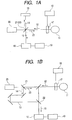
- FIG. 1A illustrates a Michelson type interferometer
- FIG. 1B illustrates a Mach-Zehnder type interferometer.
- a splitting unit 21 and a combining unit 22 is configured of common members.
- the splitting unit 21 and the combining unit 22 are configured of different members.
- the present invention is not limited to the apparatus presented by either of FIGS. 1A and 1B in which switching unit 17 (also referred as the first switching unit) such as a shutter is located on the measuring light pass.
- the switching unit also referred as the second switching
- shutter may also be located on the reference light pass.
- the apparatus may include only one of the first switching unit and the second switching unit, and the apparatus may include both of them.
- the FD-OCT includes two types that is SD-OCT (Spectral Domain OCT) and SS-OCT (Source Swept-OCT). Although in this embodiment, the following explanation is accompanied with SD-OCT type, the invention may also include the apparatus using SS-OCT.
- a light source 20 generates light (low coherence light).
- a super luminescent diode (SLD) can be applied to the light source 20.
- An amplified spontaneous emission (ASE) can also be applied to the light source 20.
- ultrashort pulse laser such as titanium sapphire laser can also be applied to the light source 20. Any others that can generate low coherence light may be applied to the light source 20.
- the wavelength of light generated from the light source 20 is 400 nm to 2pm, which is not limited in particular.
- the resolution to the depth direction increases as the bandwidth of the wavelength becomes wide. Generally, when the central wavelength is 850 nm, the resolution is 6 ⁇ m within the wavelength of 50nm and the resolution is 3pm within the wavelength of 100nm.
- a splitting unit 21 splits light from the light source 20 into reference light 14 and measuring light 23.
- a beam splitter or a fiber coupler can be applied to the splitting unit 21. Any others that can split light may be applied to the splitting unit 21.
- a ratio of the splitting may also be selected as proper to the object to be detected.
- a detecting unit (spectroscope) 16 detects combined light 15 of returning light 12 obtained by radiating the measuring light 23 to the object to be detected 11 (including living body parts such as eye of fundus) and the reference light 14 (reflected by a reference unit 13 such as mirrors to be set on the reference light path.
- the measuring light 23 may be radiated to the object to be detected 11 by an optical unit such as rens located on the measuring light path.
- the detecting unit 16 has a spectroscopic device for dispersing the combined light 15 (for example, a prism 109 in FIG. 2A ).
- the spectroscopic device is a diffraction grating or a prism and any others that can disperse light may be used.
- the detecting unit 16 has a sensor (for example, an imaging device 110 in FIG. 2A ) for detecting the light dispersed by the spectroscopic device.
- the sensor is a line sensor or a two dimensional sensor and any others that can detect light may be used.
- a switching unit 17 switches between a first state in which the detecting unit 16 can detect the combined light 15 (a state in which the returning light 12 is guided to the combining unit 22) and a second state in which the detecting unit can detect the reference light 14.
- the switching unit 17 is also referred as a first switching unit in which the first switching unit is located on the measuring light path.
- a switching unit of this embodiment may be located on the reference light path as described above, which is referred as a second switching unit.
- the first switching unit and the second switching unit may be located on the same apparatus.
- the second switching unit can switch between the first state and a third state in which the detecting unit 16 can detect the returning light.
- the switching unit 17 is desirably configured such that the light path of the measuring light 23 or the returning light 12 can be blocked (not claimed. At this point, the second state is in a blocked state.
- the switching unit 17 is desirably configured such that the transmittance of the measuring light 23 or the returning light 12 can be controlled (not claimed). In those cases, a shutter (described later) can be applied to the switching unit 17, but any others that can block the light path may be applied.
- the switching unit 17 is configured such that the light path of the measuring light 23 can be changed.
- the second state is in the changed state.
- an optical scanning unit for example, an XY scanner 104 in FIG. 2A
- any others that can change the light path may be applied.
- a controlling unit 18 controls the switching unit 17 to change the first state and the second state.
- the controlling unit 18 can control the switching unit (the second switching unit) to switch between the first state and the third state.
- the controlling unit 18 may control both of the first switching unit and the second switching unit to switch the first state, the second state and the third state.
- the controlling unit 18 may include two controlling device to control both of the first switching unit and the second switching unit, and may be configured on a single device to control the first switching unit and the second switching unit.
- the controlling unit 18 controls the switching unit 17 based on a predetermined timing (for example, FIGS. 3A to 3E ). At this point, the combined light 15 is detected by the detecting unit 16 at the timing of the first state.
- An interferometric information acquiring unit 19 acquires interferometric information (coherence components, an equation 8 described later) on the returning light 12 and the reference light 14 using the reference light 14 detected by the detecting unit 16 in the second state and the combined light 15. It is desirable that the autocorrelation component (an equation 1 described later) of the reference light 14 and the autocorrelation component (an equation 2 described later) of the returning light 12 are subtracted from the combined light 15 (an equation 7 described later) detected by the detecting unit 16. Desirably, the subtraction result (an equation 8 described later) is standardized by the autocorrelation component of the reference light 14. The Fourier transformation of the standardization result (an equation 9 described later) provides the tomographic image of the object to be detected 11.
- the autocorrelation component is a component by the reference light itself or by the returning light itself, which is included in addition to the coherence component of reference light and the returning light.
- the combined light of the reference light and the returning light include the autocorrelation component in addition to their coherence component.
- the autocorrelation component of the reference light which is a component having relatively large amount of light quantity compared to the coherence component, is desirably subtracted from the combined light.
- the OCT apparatus desirably includes a light quantity detecting unit (for example, a detector 803 in FIG. 7 ) for detecting the quantity of the measuring light and a comparing unit (not shown) for comparing the detected light quantity with a predetermined value.
- a light quantity detecting unit for example, a detector 803 in FIG. 7
- a comparing unit for comparing the detected light quantity with a predetermined value.
- the switching unit 17 desirably switches the first state to the second state.
- the light quantity of the measuring light is different from the predetermined light quantity (or is out of the range of the predetermined light quantity)
- the measuring light is not radiated out of the imaging apparatus (described later in an example 3).
- An imaging method using a Fourier domain optical coherence tomography is defined by the respective independent claim. It at least includes the steps described below.
- the autocorrelation component of the reference light or the returning light is removed from the combined light, thereby enabling an obtaining of high accuracy interferometric information.
- the changing may be among the first state, the second state and the third state.
- the method desirably includes the following steps:
- steps g) to j) are desirably executed by a subtracting unit, a standardizing unit, a transforming unit, and a tomographic image acquiring unit, respectively.
- a subtracting unit a standardizing unit
- a transforming unit a transforming unit
- a tomographic image acquiring unit a tomographic image acquiring unit
- the measuring light may not be radiated out of the imaging apparatus when the light quantity of the measuring light is different from the predetermined light quantity (or out of the range of the predetermined light quantity):
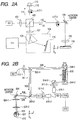
- An optical tomographic imaging apparatus is described below with reference to FIG. 2A .
- Light from a light source 101 through a splitting light path is split into measuring light 112 and reference light 114.
- the measuring light 112 is conducted to the object 106 to be detected through a measuring light path and a returning light 113 of the measuring light reflected or scattered by the object to be detected 106 is conducted to a detection position through a detecting light path.
- the reference light 114 is conducted to a reference mirror 115 through a reference light path and the reference light reflected by the reference mirror 115 is conducted to the detection position.
- the use of combined light of the returning light 113 and the reference light 114 which are conducted to the detection position images the tomographic image of the object to be detected.
- units 117-1 and 117-2 for controlling the transmittance of light are arranged on the reference light path and the measuring light path respectively.
- the unit for controlling the transmittance of light is configured to control time interval of change in the transmittance of light based on the profile set by a control unit 111.
- a unit for acquiring wavelength spectrum data 108 is configured to acquire the wavelength spectrum data of the returning light 113, the reference light 114 and the combined light based on the light from the light source that are acquired by controlling time interval based on the profile.
- a calculating unit 111 is configured to use the wavelength spectrum data of the acquired returning light, the reference light and the combined light to calculate at least any of those optical components.
- the units 117-1 and 117-2 for controlling the transmittance of light may be configured with an optical switching device for switching the transmittance and cutoff of light.
- the optical switching device may be configured with either of a mechanical or an electrical shutter.
- the mechanical or the electrical shutter may be configured to enable the transmittance of light to be controlled.
- the control unit 111 may be configured to enable control based on the profile in which the acquiring time for the returning light is set longer than the acquiring time for the reference light.
- the control unit 111 may be adapted to include an optical amplifier (for example, an optical amplifier 517 in FIG. 2B ) for amplifying the returning light.
- a method of imaging an optical tomographic image according to the present example can be configured as follows.
- the foregoing units 117-1 and 117-2 for controlling the transmittance of light are controlled based on the profile with the set time interval to obtain the returning light 113, the reference light 114 and the combined light which are based on the light from the light source.
- the wavelength spectrum data obtained from the acquired returning light, the reference light and the combined light is used to calculate at least any of those optical components.
- the wavelength spectrum data obtained from the acquired returning light, the reference light and the combined light is used to enable the subtraction of the autocorrelation components of the reference light and the returning light from the component of the combined light.
- the above subtraction result may be configured to be divided by the autocorrelation component of the reference light.
- the above division result may be configured to be divided by wavelength dispersion in the optical amplifier used for amplifying the returning light.
- the wavelength spectrum data obtained from the acquired returning light, the reference light and the combined light may be used to form an image without having depth resolution.
- measurement can be performed while noises caused by the autocorrelation components of the reference light and the returning light are sequentially being removed according to a position of an object to be detected, providing a high-resolution tomographic image.
- the above imaging method according to the present embodiment may be stored in a computer-readable storage medium (for example, a flexible disk, a hard disk, an optical disk, a magneto-optical disk, a CD-ROM, a CD-R, a magnetic tape, a nonvolatile memory card, a ROM, an EEPROM, a blue ray disk and the like) as a program to be executed by a computer.
- a computer-readable storage medium for example, a flexible disk, a hard disk, an optical disk, a magneto-optical disk, a CD-ROM, a CD-R, a magnetic tape, a nonvolatile memory card, a ROM, an EEPROM, a blue ray disk and the like.
- the optical tomographic imaging apparatus of the present example forms a Michelson type interferometer as a whole and uses a mechanical mechanism in a part of controlling light.
- Light emitted from a light source 101 passes through a lens 102 and is split into the measuring light 112 and the reference light 114 by a beam splitter 103.
- the measuring light 112 reaches the object 106 to be detected 106 through the XY scanner 104 and an object lens 105.
- a light transmissive film is arranged on the object 106 to be detected.
- the returning light 113 scattered and reflected by the surface and interface of the film returns through the object lens 105, the XY scanner 104 and the beam splitter 103 in this order and reaches a spectroscope 108 through an imaging lens 107.
- the reference light 114 is reflected by the reference mirror 115.
- the reference mirror 115 can adjust optical path length with the aid of a position adjusting device 116.
- the reference light 114 is added to the returning light by the beam splitter 103.
- the reference light 114 and the returning light 113 can be cut off by rotary shutters 117-1 and 117-2 respectively.
- the shutters 117-1 and 117-2 can continuously control the transmittance and cutoff of light by the use of a control unit (not shown). Of course the shutter does not need to be of a rotary type.
- a slide shutter may be movably arranged on the light path.
- the light source 101 uses a super luminescent diode (SLD) which is a typical low-coherent light source.
- SLD super luminescent diode
- the center wavelength thereof is 830 nm, for example, and the band width is 50 nm.
- the band width is an important factor because it affects the resolution in the optical axis of the tomographic image to be obtained.
- the SLD has been selected as the light source, any others that can emit low-coherent light may be used, e.g. an amplified spontaneous emission (ASE) light source may be used.
- ASE amplified spontaneous emission
- other light sources such as a halogen lamp and the like may be used depending upon the contents of the object to be detected.
- the wavelength affects the resolution in the lateral direction of the tomographic image to be obtained, so that it is desirable to use a short wavelength in attaching importance to lateral resolution.
- the spectroscope 108 includes the prism 109 and the imaging device 110 and disperses the returning light 113, the reference light 114 and the combined light, respectively.
- the dispersed light is captured by the imaging device in the spectroscope 108 as the spectrum data of wavelength.
- the spectrum data of wavelength imaged by the imaging device is analyzed by a computer 111.
- the computer 111 has functions not only to analyze the data, but also to issue instructions for storing data, displaying an image and measuring data.
- the XY scanner 104 raster-scans the measuring light 112 over the object 106 to be detected in the direction perpendicular to the optical axis with the aid of computer control to obtain the cross section image of the object 106 to be detected.
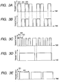
- FIGS. 3A and 3B are timing charts for describing examples of time profiles of transmittance of the reference light 114 and the returning light 113 respectively, where transmittance is 0% or 100% in the examples.
- a disk in the same circumference of which three holes are made is used and a blocking member is arranged in one hole.
- the rotation of the disk at constant speed provides such a profile.
- the reference light, the returning light and the combined light are obtained by intervals 301, 302 and 303 illustrated in FIG. 3A respectively.
- the computer 111 controls the spectroscope 108 and the XY scanner 104 based on the set control profile.
- Transmittance does not need to be 100% and may be changed in the case where only the reference light is measured and where the combined light is measured.
- the use of a ND filter in the hole of the disk enables transmittance to be changed. If the use of the ND filter changes optical path length, a glass member which is the same in optical path length is arranged in the hole of the other disk.
- the time intervals 301, 302 and 303 do not need to be equal to one another. Since the reference light is large in amount, the time intervals can be short.
- the use of a slide shutter allows optionally changing the time interval of the shutter. If the wavelength spectrum of the light source is temporally stable, a profile for continuously obtaining the returning light and the combined light can be accepted. In this case, the wavelength spectrum of the light source needs to be previously obtained.
- FIG. 4 is a flow chart for describing the processing behavior in the present example.
- step S1 measurement is started.
- step S2 the reference light 114 is obtained by the imaging device 110 while the measuring light 112 is cutoff by the shutter 117-2 and stored in a memory.
- I r (k) being the autocorrelation component of the reference light 114 is expressed by an equation 1 with a wave number k and the electric field of the reference light as E r (k).
- I r k E r k 2
- a general spectroscope acquires the spectrum of a wavelength ⁇ .
- the spectrum is considered to be equally spaced in the wave number. If the spectrum of the reference light is not temporally changed, the reference light 114 may be previously obtained and stored in the memory.
- step S3 the returning light 113 is obtained by the imaging device 110 while the reference light 114 is cutoff by the shutter 117-1.
- the spatial distance of i-th interface away from a position 401 of an equivalent reference mirror 401 is taken as z i
- a reflectivity of the interface is taken as R(z i )
- a round-trip transmittance between the reference mirror and the position z i is taken as T(z i ).
- the spectrum of the returning light 113 has information in the depth direction.
- the depth information varies with the XY coordinate of the object to be detected and measured, so that it is required for obtaining two or three dimensional image.
- the integration of the equation 2 with respect to a desired wave number provides the intensity signal of the entire returning light 113 without depth resolution.
- the equation 2 may be imaged only by a specific wave number without integration.
- a reflectivity and a transmittance at an interface in the case where light is incident on a substance with a refractive index n t from a substance with a refractive index n s can be represented by equations 3 and 4 respectively.
- the reflectivity is 0 and the transmittance is 1
- the phase is reversed at a negative reflectivity.
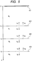
- the examples of the reflectivity R(z i ) and the round-trip transmittance T(z i ) are illustrated by using tomogram with structure as illustrated in FIG. 5 .
- the tomogram in this case is formed of a first interface 402, a second interface 403 and a third interface 404.
- the reference mirror 401 is illustrated in an optically equivalent position.
- the refractive index of the reference mirror located in an optically equivalent position and the first interface is taken as N o
- the reflectivity and the transmittance of light incident on the first interface from the side of the reference mirror are taken as r 01 and t 01 respectively.
- the transmittance of light incident on the first interface from the side of the second interface is taken as t 10 .
- the refractive index of the first interface and the second interface is taken as N 1
- the reflectivity and the transmittance of light incident on the second interface from the side of first interface are taken as r 12 and t 12 respectively
- the transmittance of light incident on the second interface from the side of the third interface is taken as t 21 .
- the refractive index of the second interface and the third interface is taken as N 2
- the reflectivity and the transmittance of light incident on the third interface from the side of the second interface are taken as r 23 and t 23 respectively and, on the other hand, the transmittance of light incident on the third interface from the side of the fourth interface is taken as t 32 .
- the refractive index of the third interface and the fourth interface is taken as N 3 .
- the reflectivity of light incident on the third interface from the side of the reference mirror can be expressed by an equation 5.
- the round-trip transmittance can be obtained by multiplying together the transmittances of the interfaces through which light passes and represented by an equation 6.
- step S4 the combined light I add (k) of the reference light 114 and the returning light 113 is obtained by the imaging device 110 while the shutter 117-1 and the shutter 117-2 does not cutoff the light.
- a coherence component I rs (k) as well as the autocorrelation components of the reference light 114 and the returning light 113 appears.
- the Fourier transformation of the equation 9 causes a signal corresponding to R(z i )T(z i ) to appear in a position of an optical distance n(z i )z i , providing a tomographic image.
- the equations 8 and 9 may be calculated after each of the desired returning light 113, reference light 114 and combined light have been obtained.
- the results of Fourier transformation in the equation 9 are accumulated to be used as a confocal laser scanning ophthalmoscopy image. That is to say, actually, light returning from the object 106 is weak, so that the returning light 113 expressed by the equation 2 sometimes cannot be measured. In such case, the multiplication of the reference light 114 by the returning light as expressed by the equation 7 allows the detection of the component of the returning light 113.
- step S5 a judgment is made as to whether a desired region has been measured. If the measurement is finished, the process proceeds to step S10.
- step S6 The term "desired region” refers to, for example, 512 points at a 20- ⁇ m step in the X direction or 512 points at a 20- ⁇ m step in the Y direction on the object to be detected. Of course the distance and the number of points may be different with an object to be detected and an apparatus.
- step S6 a judgment is made as to whether movement is performed in the X direction.
- step S7 If the movement is performed in the X direction, the process proceeds to step S7. If not, the process proceeds to step S8.
- step S7 the movement is performed by a desired distance in the X direction and the process proceeds to step S8.
- the term "desired distance” is 20 ⁇ m, for example.
- step S8 a judgment is made as to whether movement is performed in the Y direction.
- step S9 If the movement is performed in the Y direction, the process proceeds to step S9. If not, the process proceeds to step S2.
- step S9 the movement is performed by a desired distance in the Y direction and the process proceeds to step S2.
- the term "desired distance” is 20 ⁇ m, for example.
- step S10 measurement is finished.
- the interface in FIG. 5 is displayed as a tomographic image.
- the combined light is expressed by the equation 7 and the required components are expressed by the equation 8.
- the autocorrelation components of the reference light 114 and the returning light 113 are noises, so that the components need to be removed.
- the autocorrelation component of the reference light as an image which gradually attenuates from a peak as its original point to a position away from the original point, overlaps with the tomographic image.
- the autocorrelation component is folded, as shown in the equation 8, distorting the tomographic image.
- the autocorrelation components of the returning light 113 interfere with each other at the first, second and third interfaces.
- the autocorrelation component of the returning light is more extensive than the component attributed to the reference light.
- the distance between the reference mirror located in an optically equivalent position and the first mirror needs to be greater than the thickness of layer of the object to be detected.
- the tomographic component can be separated from the autocorrelation component even if a layer is displayed as if to lie between the reference mirror 401 located in an optically equivalent position and the first mirror 402.
- the removal of the autocorrelation components of the reference light 114 and the returning light 113 allows the reference mirror 401 located in an optically equivalent position to be arranged in a position near the first interface.
- the arrangement of the reference mirror 401 located in an optically equivalent position in a position near the first interface enables a high sensitive measurement, which is especially effective for the object to be detected that is low in reflectivity like the eyes.
- the division with the spectrum of the reference light 114 eliminates the distortion of a tomographic image to provide a high resolution image.
- FIG. 2B is a schematic diagram for describing an optical system for the optical tomographic imaging apparatus in the present example.
- the optical tomographic imaging apparatus of the present example forms a Mach-Zehnder type interferometer as a whole and uses an electrical mechanism in a part of controlling light.
- the object to be detected is the eyes, so that the returning light is small in amount.
- the use of the optical amplifier 517 for amplifying the returning light enables a high-speed light control.
- a light source 501 Light emitted from a light source 501 is conducted to a lens 511-1 to 511-3 through a single mode fiber 512-1 and split into the reference light 505 and the measuring light 506 by a beam splitter 503-1 and 503-2.
- the measuring light 506 is reflected or scattered by the eye as an object to be detected 507 being the object to be detected and returned as returning light 508.
- the reference light and the returning light are incident on a spectroscope 518 through a fiber coupler 521. Data such as wavelength spectrum obtained by the spectroscope is captured in a computer 519.
- the light source 501 uses a super luminescent diode (SLD) being a typical low-coherent light source. In consideration of measuring the eyes, near infrared light is suitable as a wavelength.
- SLD super luminescent diode
- the light path for the reference light 505 is described below.
- the reference light 505 split by the beam splitter 503-1 is sequentially incident on mirrors 514-1, 514-2 and 514-3 to be changed in its direction, converged by a lens 511-3 and incident on an optical switch 516-1.
- a directivity-coupler optical switch in which light is switched by changing a refractive index as the optical switch.
- a Mach-Zehnder type interferometer optical switch a gate-type optical switch using an optical gate element capable of controlling the transmittance of light and a total internal reflection type optical switch using a semiconductor.
- a dispersion compensation glass 515 is L1 in length, which desirably doubles the depth of a normal eye.
- the dispersion compensation glass 515 compensates dispersion of the measuring light 506 traveling to and from the eye 507 for the reference light 505.
- the length L is taken as 46 mm, which doubles the diameter of an average Japanese eyeball of 23 mm.
- An electric stage 513 can be moved in the direction indicated by an arrow in the figure and adjust and control the light path length of the reference light 505.
- the light path for the measuring light 506 is described below.
- the measuring light 506 split by the beam splitter 503-1 is reflected by the beam splitter 503-2 and then incident on the mirror of an XY scanner 504.
- the XY scanner 504 performs a raster-scan on a retina 510 in the direction perpendicular to the optical axis.
- the center of the measuring light 506 is adjusted to coincide with the rotation center of the mirror of the XY scanner 504.
- the lenses 520-1 and 520-2 is an optical system for scanning the retina 510 and plays a role to scan the measuring light 506 over the retina 510 with the vicinity of the cornea 509 as fulcrum.
- the lenses 520-1 and 520-2 are 50 mm and 50 mm in focal distance respectively.
- the incidence of the measuring light 506 on the eye 507 produces the returning light 508 by reflection and/or scatter from the retina 510.
- the returning light 508 passes through the optical amplifier 517, is converged by a lens 511-2 and led to the spectroscope 518 through an optical switch 516-2 and the fiber coupler 521.
- the optical amplifier uses a semiconductor amplifier. Some optical amplifiers can be used as a gate element for changing transmittance.
- gate-type optical switch allows the elimination of the optical amplifier 517 and the integration of the optical switch 516 and the fiber coupler 521.
- FIGS. 3C and 3D are profiles of the reference light and the returning light respectively.
- Transmittance is desirably 0% or 100% but a waveguide light path sometimes generates a little loss and leakage.
- the reference light, the returning light and the combined light are obtained by intervals 301, 302 and 303 illustrated in FIG. 3C respectively.
- FIG. 6 is a flow chart for describing the signal processing in the present example.
- step S1 measurement is started.
- step S2-1 a judgment is made as to whether the reference light is obtained.
- the judgment as to whether the reference light is obtained is made based on a control profile.
- step S2-2 If the reference light is obtained, the process proceeds to step S2-2, and if no, the process proceeds to step S3-1.
- step S2-2 the reference light 505 is obtained by a spectroscope 518 while the returning light 508 is cutoff by the optical switch 516-2 and stored in a memory.
- Intensity I r (k) being the autocorrelation component of the reference light is expressed by the equation 1.
- step S3-1 a judgment is made as to whether the returning light is obtained.
- the judgment as to whether the returning light is obtained is made based on the control profile.
- step S3-2 If the returning light is obtained, the process proceeds to step S3-2, and if no, the process proceeds to step S4-1.
- step S3-2 the returning light 508 is obtained by a spectroscope 518 while the reference light 505 is cutoff by the optical switch 516-1.
- the intensity I s (k) being the autocorrelation component of the returning light is different from that of the example 1 and can be expressed by an equation 10 in which the equation 2 is multiplied by a wavelength dispersion G(k) of the optical amplifier.
- wavelength dispersion generated due to a difference between devices in the light path is included in G(k)
- a range may be increased.
- step S4-1 a judgment is made as to whether the combined light is obtained.
- the judgment as to whether the combined light is obtained is made based on the control profile.
- step S4-2 If the combined light is obtained, the process proceeds to step S4-2, and if no, the process proceeds to step S5.
- step S4-2 the combined light I add (k) is obtained by a spectroscope 518 while the reference light 505 and the returning light 508 is cutoff by the optical switch 516-1 and 516-2, respectively.
- a coherence component I rs (k) as well as the autocorrelation components of the reference light and the returning light appears.
- the subtraction of the equations 1 and 10 from the combined light I add (k) provides an equation 11.
- the equation 12 is different from the equation 9 in that the equation 12 is multiplied by the wavelength dispersion G(k) of the optical amplifier, the division of the equation 12 by G(k) provides the equation 9 in the example 1.
- the wavelength dispersion of the optical amplifier is previously obtained and stored in a memory.
- a mirror for example, is arranged instead of the eyes, the spectra of the reference light and the returning light are obtained and calculated to obtain the wavelength dispersion of the optical amplifier.
- step S5 a judgment is made as to whether measurement is finished.
- step S10 If the measurement is to be finished, the process proceeds to step S10. If no, the process proceeds to step S6.
- step S6 a judgment is made as to whether movement is performed in the X direction.
- step S7 If the movement is performed in the X direction, the process proceeds to step S7. If not, the process proceeds to step S8.
- step S7 the movement is performed by a desired distance in the X direction and the process proceeds to step S8.
- step S8 a judgment is made as to whether movement is performed in the Y direction.
- step S9 If the movement is performed in the Y direction, the process proceeds to step S9. If not, the process proceeds to step S2-1.
- step S9 the movement is performed by a desired distance in the Y direction and the process proceeds to step S2-1. If it is finally determined in step S5 through the above steps that measurement is finished, the process proceeds to step S10 to finish the measurement.
- the use of an electrical optical switch allows a high speed measurement. Furthermore, the use of the optical amplifier enables even weak light to be measured. Still furthermore, the calculation provides a high resolution tomographic image at a high speed.
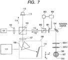
- FIG. 7 is a schematic diagram for describing an optical system for the optical tomographic imaging apparatus in the present example.
- the same reference number refers the same component as in FIGs 2A and 2B , and the points different from the examples 1 and 2 are described below.
- the shutter prevents the measuring light to radiate out of the imaging apparatus when the light quantity of the measuring light is different from the predetermined light quantity (or is out of the range of the predetermined light quantity).
- a shutter 801 opens and closes the light path through an electrical circuit in response to instructions from the computer 111.
- a beam splitter 802 splits the measuring light 112 into a light for a detector 803 and a measuring light for an object to be measured.
- a detector 803 detects the quantity of light and inputs a signal thereof to an electrical circuit 804.
- the detector is a photo diode, for example, and a current-voltage converter therein converts current to voltage and the voltage signal is input to the electrical circuit.
- the shutter includes electrical-optical, magneto-optic and mechanical shutters.
- the electrical-optical shutter is formed such that a prism electrode is arranged on an optical deflection element of PLZT:(Pb, La)(Zr, Ti)O 3 .
- the application of voltage to the prism electrode changes the refractive index in a prism shape to allow the beam to be bent. Transmittance and cutoff can be switched by the angle of the beam.
- the response speed ranges from several nanoseconds to several hundred nanoseconds.
- the magneto-optic shutter is formed such that a magneto-optic element wrapped with a magnetic coil, for example, is arranged between polarizers rectangular to each other.
- the response speed ranges from several microseconds to several hundred microseconds.
- the mechanical shutter changes the angle of the mirror using a MEMS device, for example, enabling switching the transmittance and cutoff of light.
- the response speed ranges from several hundred microseconds to several milliseconds. Moving a blocking object to and from the light path by means of a magnetic coil allows switching the transmittance and cutoff of light.
- the response speed ranges from several tens of milliseconds to several hundred milliseconds.
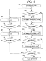
- a flow chart of the example 3 is described below with reference to FIG. 8 .
- step A1 The process starts in step A1 and proceeds to steps A2 and M1.
- step M1 the quantity of light is detected by the detector 803 and monitored by the electric circuit 804.
- the step A2 is stand-by time until the monitor of quantity of light is surely started and the stand-by time is several tens of milliseconds, for example.
- step M2 a confirmation is made as to whether the quantity of light is within a specified range and measurement is not finished. If the above conditions are satisfied, the process returns to step M1 (801). Note that the specified quantity of light is determined by the standard such as ANSI, e.g. 700 ⁇ W. If the quantity of light is not within a specified range, e.g. not within 680-700 ⁇ m, the process proceeds to step M3 (802). If measurement is finished, the process proceeds to step A10 and ends (803).
- step M3 if the shutter is opened at this moment, the shutter is closed. Thereafter, the process proceeds to step M4 to process error handling.
- error handling means that the acquisition of data by a spectroscope is stopped by a computer to return a scanner and a reference mirror to an initial position, and so on. In addition, an error message is output on a screen of the computer.
- step A3 the shutter is opened. Opening the shutter causes the measuring light to reach the eye to be examined to cause the returning light to reach the spectroscope, enabling the combined light to be measured.
- the quantity of light is monitored once or more in step M1 during the stand-by time in step A2.
- step A4 the scanner is moved to a desired position.
- the movement of the scanner refers to scan in the X and Y directions.
- the scanner is moved in the X and Y directions on the assumption that 3D measurement is performed to obtain data of 512 points ⁇ 512 points in the XY plane.
- the X direction is taken as Fast-Axis in which a round-trip scanning is performed at a high speed.
- the Y direction is taken as Slow-Axis in which a unidirectional scanning is performed at a low speed.
- step A5 a judgment is made as to whether the state of the shutter is changed.
- the change of state of the shutter changes the state of transmittance or cutoff of light. If the change of state is required, the process proceeds to step A6 to change state of the shutter. If the change of state is not required, the process proceeds to step A7.
- step A7 measurement is performed by a spectroscope 108.
- the reference light When the shutter is closed, the reference light can be measured because the returning light does not exist.
- the intensity of the reference light corresponds to the equation 1.
- the combined light can be measured because the returning light exists.
- the intensity of the combined light corresponds to the equation 7.
- the autocorrelation component of the returning light from the eye to be examined is very weak and the intensity of the returning light (equation 2) can be regarded as zero.
- the reference light is subtracted from the combined light and the result is divided by the autocorrelation component of the reference light provides the equation 9.
- the Fourier transformation of the equation 9 provides a tomographic image.
- the above signal processing may be collectively performed after the measurement has been finished.
- FIG. 3E illustrates the profile of the measuring light controlled by the shutter.
- the figure illustrates the profile obtained by repeating the steps A4 to A8 three times.
- the reference light is measured in the interval 301.
- the stage is moved in the Y direction during the interval 301, and moved back in the X direction by a distance moved during the interval 302.
- the reference light is measured once during the interval.
- the combined light is measured in the interval 302.
- the stage is moved in the X direction at a constant speed during the interval 302 and not moved in the Y direction.
- the combined light is measured 512 times during the interval.
- step A9 the shutter is closed.
- the shutter is originally closed, the shutter is kept as it is.
- step A10 the measurement is finished.
- a shutter to shut off the measuring light is located on the measuring light path and the shutter is used while reference light is detected, thereby the stability of the measuring light during the detection is enabled with much simple circuit configuration.
Landscapes
- Health & Medical Sciences (AREA)
- Life Sciences & Earth Sciences (AREA)
- Physics & Mathematics (AREA)
- General Health & Medical Sciences (AREA)
- Animal Behavior & Ethology (AREA)
- Public Health (AREA)
- Veterinary Medicine (AREA)
- Engineering & Computer Science (AREA)
- Biomedical Technology (AREA)
- Heart & Thoracic Surgery (AREA)
- Medical Informatics (AREA)
- Molecular Biology (AREA)
- Surgery (AREA)
- Pathology (AREA)
- Biophysics (AREA)
- Radiology & Medical Imaging (AREA)
- Nuclear Medicine, Radiotherapy & Molecular Imaging (AREA)
- Ophthalmology & Optometry (AREA)
- Chemical & Material Sciences (AREA)
- Analytical Chemistry (AREA)
- Biochemistry (AREA)
- General Physics & Mathematics (AREA)
- Immunology (AREA)
- Optics & Photonics (AREA)
- Investigating Or Analysing Materials By Optical Means (AREA)
- Eye Examination Apparatus (AREA)
Description
- The present invention relates to an imaging apparatus and an imaging method using optical coherence tomography, specifically for an imaging apparatus and an imaging method used for observing the eye and the skin using the optical coherence tomography.
- There has been put into practical use an imaging apparatus using optical coherence tomography (OCT) taking advantage of coherence of low coherence light (hereinafter referred to as OCT apparatus). The imaging apparatus can obtain a tomographic image with resolution on the order of a wavelength of light incident on an object, which enables providing a high-resolution tomographic image of an object to be detected.
- Light from a light source is split into measuring light and reference light by a splitting light path such as a beam splitter. An object to be detected such as the eyes is first irradiated with the measuring light through a measuring light path. The light returning from the object to be detected is then conducted to a detecting position through a detecting light path. The term "returning light" refers to reflected light and scattered light including information on an interface in the direction in which the object to be detected is irradiated with light. The reference light is reflected by a reference mirror through a reference light path to conduct the reflected light to the detecting position. The detection and analysis of the coherent light of the returning light and the reference light with a detector provides a tomographic image of the object to be detected.
- Japanese Patent Application Laid-Open No.
H11-325849 - Furthermore, there is disclosed a Fourier-Domain OCT apparatus (hereinafter referred to as FD-OCT apparatus) in which wavelength spectra are obtained with a reference mirror of the OCT apparatus fixed and a tomogram is measured by Fourier transformation, in a paper; A. F. Fercher, C. K. Hitzenberger, G. Kamp, S. Y. El-Zaiat, Opt. Commun. 117, 43-48, (1995). The FD-OCT apparatus includes a system using a spectroscope (SD-OCT:Spectral Domain OCT) and a system sweeping the wavelength of a light source (SS-OCT:Source Swept-OCT).
- Prior art which is related to this field of technology can be found e.g. in non-patent literature Al JUN ET AL: "Spectral-domain optical coherence tomography: Removal of autocorrelation using an optical switch", APPLIED PHYSICS LETTERS, AIP, AMERICAN INSTITUTE OF PHYSICS, MELVILLE, NY, US, vol 88, no. 11, 15 March 2006 (2006-03-15), pages 111115-111115.
- It requires more time for the OCT apparatus disclosed in Japanese Patent Application Laid-Open No.
H11-325849 - On the other hand, the FD-OCT apparatus can use the fixed reference mirror in collectively obtaining tomographic images in the depth direction. However, the autocorrelation components of the reference light and the returning light are included in the combined light of the reference light and the returning light as noise.
For avoiding this, the reference mirror located in an optically equivalent position may be away from the object to be detected to be isolated from these components. Also for avoiding this, coherence gate may be away from the object to be detected in order to be isolated from those components. - However, the reference mirror located in an optically equivalent position being away from the object sometimes decreases measuring sensitivity (sensitivity of the sensor), and the autocorrelation components of the reference light and the returning light need to be removed from the combined light to perform high accuracy measurement. In particular, the autocorrelation component of the returning light is varied with locations to be measured, so that the autocorrelation component of the returning light needs to be sequentially obtained to be removed from the combined light.
- The present invention has been made in view of the above problems and it is an object of the present invention to provide an optical tomographic imaging apparatus configured in the following manner and a method of imaging an optical tomographic image.
- According to the present invention, there are provided an optical tomographic imaging apparatus and an imaging method according to the respective claims.
- According to the present invention, the removal of the autocorrelation component of the reference light allows providing a high accuracy tomographic image.
- Further features of the present invention will become apparent from the following description of exemplary embodiments with reference to the attached drawings.
-
-
FIGS. 1A and 1B are schematic diagrams for describing imaging apparatus using optical coherence tomography according to the present embodiment. -
FIGS. 2A and 2B are schematic diagrams for describing optical systems of the imaging apparatus using the optical coherence tomography according to examples 1 and 2. -
FIGS. 3A, 3B, 3C, 3D and 3E are timing charts for describing control profiles for reference and returning lights in examples 1 to 3. -
FIG. 4 is a flow chart for measurement in the example 1. -
FIG. 5 is a schematic diagram for describing the structure of tomogram and a relationship of reflectivity and transmittance in the example 1. -
FIG. 6 is a flow chart of measurement in the example 2. -
FIG. 7 is a schematic diagram for describing an optical system for an image apparatus using optical coherence tomography in the example 3. -
FIG. 8 is a flow chart of measurement in the example 3. - An imaging apparatus using a Fourier domain optical coherence tomography according to the present embodiment is described below with reference to
FIGS. 1A and 1B. FIG. 1A illustrates a Michelson type interferometer andFIG. 1B illustrates a Mach-Zehnder type interferometer. InFIG. 1A , asplitting unit 21 and a combiningunit 22 is configured of common members. InFIG. 1B , on the other hand, thesplitting unit 21 and the combiningunit 22 are configured of different members. - The present invention is not limited to the apparatus presented by either of
FIGS. 1A and 1B in which switching unit 17 (also referred as the first switching unit) such as a shutter is located on the measuring light pass. The switching unit (also referred as the second switching) such as shutter may also be located on the reference light pass. The apparatus may include only one of the first switching unit and the second switching unit, and the apparatus may include both of them. - The FD-OCT (Fourier Domain OCT) includes two types that is SD-OCT (Spectral Domain OCT) and SS-OCT (Source Swept-OCT). Although in this embodiment, the following explanation is accompanied with SD-OCT type, the invention may also include the apparatus using SS-OCT.
- A
light source 20 generates light (low coherence light). A super luminescent diode (SLD) can be applied to thelight source 20. An amplified spontaneous emission (ASE) can also be applied to thelight source 20. In addition, ultrashort pulse laser such as titanium sapphire laser can also be applied to thelight source 20. Any others that can generate low coherence light may be applied to thelight source 20. The wavelength of light generated from thelight source 20 is 400 nm to 2pm, which is not limited in particular. The resolution to the depth direction increases as the bandwidth of the wavelength becomes wide. Generally, when the central wavelength is 850 nm, the resolution is 6µm within the wavelength of 50nm and the resolution is 3pm within the wavelength of 100nm. - A splitting
unit 21 splits light from thelight source 20 intoreference light 14 and measuringlight 23. A beam splitter or a fiber coupler can be applied to thesplitting unit 21. Any others that can split light may be applied to thesplitting unit 21. A ratio of the splitting may also be selected as proper to the object to be detected. - A detecting unit (spectroscope) 16 detects combined
light 15 of returning light 12 obtained by radiating the measuringlight 23 to the object to be detected 11 (including living body parts such as eye of fundus) and the reference light 14 (reflected by areference unit 13 such as mirrors to be set on the reference light path. The measuringlight 23 may be radiated to the object to be detected 11 by an optical unit such as rens located on the measuring light path. The detectingunit 16 has a spectroscopic device for dispersing the combined light 15 (for example, aprism 109 inFIG. 2A ). The spectroscopic device is a diffraction grating or a prism and any others that can disperse light may be used. The detectingunit 16 has a sensor (for example, animaging device 110 inFIG. 2A ) for detecting the light dispersed by the spectroscopic device. The sensor is a line sensor or a two dimensional sensor and any others that can detect light may be used. - A switching
unit 17 switches between a first state in which the detectingunit 16 can detect the combined light 15 (a state in which the returninglight 12 is guided to the combining unit 22) and a second state in which the detecting unit can detect thereference light 14. The switchingunit 17 is also referred as a first switching unit in which the first switching unit is located on the measuring light path. A switching unit of this embodiment may be located on the reference light path as described above, which is referred as a second switching unit. The first switching unit and the second switching unit may be located on the same apparatus. The second switching unit can switch between the first state and a third state in which the detectingunit 16 can detect the returning light. - The switching
unit 17 is desirably configured such that the light path of the measuringlight 23 or the returninglight 12 can be blocked (not claimed. At this point, the second state is in a blocked state. The switchingunit 17 is desirably configured such that the transmittance of the measuringlight 23 or the returninglight 12 can be controlled (not claimed). In those cases, a shutter (described later) can be applied to theswitching unit 17, but any others that can block the light path may be applied. - According to the invention, the switching
unit 17 is configured such that the light path of the measuringlight 23 can be changed. At this point, the second state is in the changed state. In this case, an optical scanning unit (for example, anXY scanner 104 inFIG. 2A ) for scanning the measuringlight 23 on the object to be detected 11, for example, can be applied to theswitching unit 17, but any others that can change the light path may be applied. - A controlling unit 18 (the first switching unit) controls the switching
unit 17 to change the first state and the second state. The controllingunit 18 can control the switching unit (the second switching unit) to switch between the first state and the third state. The controllingunit 18 may control both of the first switching unit and the second switching unit to switch the first state, the second state and the third state. The controllingunit 18 may include two controlling device to control both of the first switching unit and the second switching unit, and may be configured on a single device to control the first switching unit and the second switching unit. Desirably, the controllingunit 18 controls the switchingunit 17 based on a predetermined timing (for example,FIGS. 3A to 3E ). At this point, the combinedlight 15 is detected by the detectingunit 16 at the timing of the first state. - An interferometric
information acquiring unit 19 acquires interferometric information (coherence components, an equation 8 described later) on the returninglight 12 and thereference light 14 using thereference light 14 detected by the detectingunit 16 in the second state and the combinedlight 15. It is desirable that the autocorrelation component (anequation 1 described later) of thereference light 14 and the autocorrelation component (an equation 2 described later) of the returninglight 12 are subtracted from the combined light 15 (anequation 7 described later) detected by the detectingunit 16. Desirably, the subtraction result (an equation 8 described later) is standardized by the autocorrelation component of thereference light 14. The Fourier transformation of the standardization result (anequation 9 described later) provides the tomographic image of the object to be detected 11. - This allows sequentially providing the returning
light 12 which may vary with locations to be measured. Thereby, the autocorrelation component of the returninglight 12 can be removed from the combinedlight 15. - The autocorrelation component is a component by the reference light itself or by the returning light itself, which is included in addition to the coherence component of reference light and the returning light. The combined light of the reference light and the returning light include the autocorrelation component in addition to their coherence component. In order to detect the coherent component, the autocorrelation component of the reference light, which is a component having relatively large amount of light quantity compared to the coherence component, is desirably subtracted from the combined light.
- The OCT apparatus desirably includes a light quantity detecting unit (for example, a
detector 803 inFIG. 7 ) for detecting the quantity of the measuring light and a comparing unit (not shown) for comparing the detected light quantity with a predetermined value. When the detected light quantity is different from the predetermined value (predetermined light quantity) or the detected light quantity is out of the range of the predetermined light quantity, the switchingunit 17 desirably switches the first state to the second state. As a result, when the light quantity of the measuring light is different from the predetermined light quantity (or is out of the range of the predetermined light quantity), the measuring light is not radiated out of the imaging apparatus (described later in an example 3). - An imaging method using a Fourier domain optical coherence tomography according to the present embodiment is defined by the respective independent claim. It at least includes the steps described below.
- a) a step of generating a light.
- b) a step of splitting the light into a reference light and a measuring light.
- c) a step of irradiating the measuring light to an object to be detected.
- d) a step of detecting the combined light obtained by combining the reference light and the returning light obtained by the irradiation.
- e) a step of switching between a first state in which the detecting
unit 16 can detect the combined light and a second state in which the detecting unit can detect the reference light, or between the first state and a third state in which the detectingunit 16 can detect the measuring light. - f) a step of obtaining interferometric information on the returning light and the reference light by using the combined light detected in the first state and one of the reference light detected in the second state and the measuring light detected in the third state.
- By using this method, the autocorrelation component of the reference light or the returning light is removed from the combined light, thereby enabling an obtaining of high accuracy interferometric information.
- In the step e), the changing may be among the first state, the second state and the third state.
- In order to obtain still accurate tomographic information, the method desirably includes the following steps:
- g) a step of subtracting the autocorrelation component of the reference light and the autocorrelation component of the returning light from the combined light.
- h) a step of standardizing the subtracted value by the autocorrelation component of the reference light.
- i) a step of Fourier transforming the standardized result.
- j) a step of obtaining the tomographic image of the object to be detected.
- Above steps g) to j) are desirably executed by a subtracting unit, a standardizing unit, a transforming unit, and a tomographic image acquiring unit, respectively. Each of the above unit is not necessarily divided into different processor such as CPU, but a single processor may include each of them.
- When the method includes further steps below, the measuring light may not be radiated out of the imaging apparatus when the light quantity of the measuring light is different from the predetermined light quantity (or out of the range of the predetermined light quantity):
- k) a step of detecting the light quantity of the measuring light.
- l) a step to change to the second state when the light quantity is different from the predetermined light quantity.
- An optical tomographic imaging apparatus according to another example is described below with reference to
FIG. 2A . Light from alight source 101 through a splitting light path is split into measuring light 112 andreference light 114. The measuringlight 112 is conducted to theobject 106 to be detected through a measuring light path and a returninglight 113 of the measuring light reflected or scattered by the object to be detected 106 is conducted to a detection position through a detecting light path. On the other hand, thereference light 114 is conducted to areference mirror 115 through a reference light path and the reference light reflected by thereference mirror 115 is conducted to the detection position. The use of combined light of the returning light 113 and thereference light 114 which are conducted to the detection position images the tomographic image of the object to be detected. At this point, units 117-1 and 117-2 for controlling the transmittance of light are arranged on the reference light path and the measuring light path respectively. The unit for controlling the transmittance of light is configured to control time interval of change in the transmittance of light based on the profile set by acontrol unit 111. A unit for acquiringwavelength spectrum data 108 is configured to acquire the wavelength spectrum data of the returning light 113, thereference light 114 and the combined light based on the light from the light source that are acquired by controlling time interval based on the profile. A calculatingunit 111 is configured to use the wavelength spectrum data of the acquired returning light, the reference light and the combined light to calculate at least any of those optical components. - The units 117-1 and 117-2 for controlling the transmittance of light may be configured with an optical switching device for switching the transmittance and cutoff of light. In addition, the optical switching device may be configured with either of a mechanical or an electrical shutter. The mechanical or the electrical shutter may be configured to enable the transmittance of light to be controlled. The
control unit 111 may be configured to enable control based on the profile in which the acquiring time for the returning light is set longer than the acquiring time for the reference light. Furthermore, thecontrol unit 111 may be adapted to include an optical amplifier (for example, anoptical amplifier 517 inFIG. 2B ) for amplifying the returning light. - A method of imaging an optical tomographic image according to the present example can be configured as follows. The foregoing units 117-1 and 117-2 for controlling the transmittance of light are controlled based on the profile with the set time interval to obtain the returning light 113, the
reference light 114 and the combined light which are based on the light from the light source. The wavelength spectrum data obtained from the acquired returning light, the reference light and the combined light is used to calculate at least any of those optical components. - In calculating the optical component, the wavelength spectrum data obtained from the acquired returning light, the reference light and the combined light is used to enable the subtraction of the autocorrelation components of the reference light and the returning light from the component of the combined light. Furthermore, in calculating a component of the light, the above subtraction result may be configured to be divided by the autocorrelation component of the reference light. Still furthermore, in calculating a component of the light, the above division result may be configured to be divided by wavelength dispersion in the optical amplifier used for amplifying the returning light. The wavelength spectrum data obtained from the acquired returning light, the reference light and the combined light may be used to form an image without having depth resolution.
- According to the optical tomographic imaging apparatus and the method of imaging an optical tomographic image according to the present embodiment, measurement can be performed while noises caused by the autocorrelation components of the reference light and the returning light are sequentially being removed according to a position of an object to be detected, providing a high-resolution tomographic image.
- As another embodiment, the above imaging method according to the present embodiment may be stored in a computer-readable storage medium (for example, a flexible disk, a hard disk, an optical disk, a magneto-optical disk, a CD-ROM, a CD-R, a magnetic tape, a nonvolatile memory card, a ROM, an EEPROM, a blue ray disk and the like) as a program to be executed by a computer. As further another embodiment, there may be a program for causing a computer to execute the above imaging method.
- Examples useful for understanding the present invention are described below.
- There is described an example of an imaging apparatus (or an optical tomographic imaging apparatus) using optical coherence tomography according to the example 1 with reference to
FIG. 2A . The optical tomographic imaging apparatus of the present example forms a Michelson type interferometer as a whole and uses a mechanical mechanism in a part of controlling light. - Light emitted from a
light source 101 passes through alens 102 and is split into the measuringlight 112 and thereference light 114 by abeam splitter 103. The measuringlight 112 reaches theobject 106 to be detected 106 through theXY scanner 104 and anobject lens 105. A light transmissive film is arranged on theobject 106 to be detected. The returning light 113 scattered and reflected by the surface and interface of the film returns through theobject lens 105, theXY scanner 104 and thebeam splitter 103 in this order and reaches aspectroscope 108 through animaging lens 107. On the other hand, thereference light 114 is reflected by thereference mirror 115. Thereference mirror 115 can adjust optical path length with the aid of aposition adjusting device 116. Thereference light 114 is added to the returning light by thebeam splitter 103. Thereference light 114 and the returning light 113 can be cut off by rotary shutters 117-1 and 117-2 respectively. The shutters 117-1 and 117-2 can continuously control the transmittance and cutoff of light by the use of a control unit (not shown). Of course the shutter does not need to be of a rotary type. A slide shutter may be movably arranged on the light path. - The
light source 101 uses a super luminescent diode (SLD) which is a typical low-coherent light source. The center wavelength thereof is 830 nm, for example, and the band width is 50 nm. The band width is an important factor because it affects the resolution in the optical axis of the tomographic image to be obtained. Although the SLD has been selected as the light source, any others that can emit low-coherent light may be used, e.g. an amplified spontaneous emission (ASE) light source may be used. Of course other light sources such as a halogen lamp and the like may be used depending upon the contents of the object to be detected. However, the wavelength affects the resolution in the lateral direction of the tomographic image to be obtained, so that it is desirable to use a short wavelength in attaching importance to lateral resolution. - The
spectroscope 108 includes theprism 109 and theimaging device 110 and disperses the returning light 113, thereference light 114 and the combined light, respectively. The dispersed light is captured by the imaging device in thespectroscope 108 as the spectrum data of wavelength. The spectrum data of wavelength imaged by the imaging device is analyzed by acomputer 111. Thecomputer 111 has functions not only to analyze the data, but also to issue instructions for storing data, displaying an image and measuring data. TheXY scanner 104 raster-scans the measuring light 112 over theobject 106 to be detected in the direction perpendicular to the optical axis with the aid of computer control to obtain the cross section image of theobject 106 to be detected. - A time profile of transmittance of the
reference light 114 and the returning light 113 in the present example is described below with reference toFIGS. 3A and 3B. FIGS. 3A and 3B are timing charts for describing examples of time profiles of transmittance of thereference light 114 and the returning light 113 respectively, where transmittance is 0% or 100% in the examples. - For the rotary shutter, a disk in the same circumference of which three holes are made is used and a blocking member is arranged in one hole. The rotation of the disk at constant speed provides such a profile. The reference light, the returning light and the combined light are obtained by
intervals FIG. 3A respectively. Of course, thecomputer 111 controls thespectroscope 108 and theXY scanner 104 based on the set control profile. - Transmittance does not need to be 100% and may be changed in the case where only the reference light is measured and where the combined light is measured. For the rotary shutter, for example, the use of a ND filter in the hole of the disk enables transmittance to be changed. If the use of the ND filter changes optical path length, a glass member which is the same in optical path length is arranged in the hole of the other disk. The
time intervals - Processing behavior in the present example is described below with reference to
FIG. 4. FIG. 4 is a flow chart for describing the processing behavior in the present example. - In step S1, measurement is started.
- In step S2, the
reference light 114 is obtained by theimaging device 110 while the measuringlight 112 is cutoff by the shutter 117-2 and stored in a memory. - Intensity Ir(k) being the autocorrelation component of the
reference light 114 is expressed by anequation 1 with a wave number k and the electric field of the reference light as Er(k).
- Of course, a general spectroscope acquires the spectrum of a wavelength λ.
- The spectrum of the wavelength λ is converted to the spectrum of a wave number by using the relationship of the wave number k to the wavelength λ being k = 2π/λ. It is desirable to resample a spectrum equally spaced in the wave number in consideration of Fourier transformation in the later process.
- Herein, the spectrum is considered to be equally spaced in the wave number. If the spectrum of the reference light is not temporally changed, the
reference light 114 may be previously obtained and stored in the memory. - In step S3, the returning light 113 is obtained by the
imaging device 110 while thereference light 114 is cutoff by the shutter 117-1. - There is determined the relationship among the intensity Is(k) of the returning light 113, the electric field Es(k) of the returning light 113and the electric field Er(k) of the
reference light 114. - As illustrated in
FIG. 5 , the spatial distance of i-th interface away from aposition 401 of anequivalent reference mirror 401 is taken as zi, a reflectivity of the interface is taken as R(zi) and a round-trip transmittance between the reference mirror and the position zi is taken as T(zi). - The use of an average refractive index to the position zi taken as n(zi) allows representing an intensity Is(k) being the autocorrelation component of the returning light 113 by an equation 2.
- Incidentally, herein, it is assumed that the
reference light 114 and the measuring light 112 are equally split and the spectra thereof are equal to each other. An imaginary unit is denoted by "j".
- Thus, the spectrum of the returning light 113 has information in the depth direction.
- The depth information varies with the XY coordinate of the object to be detected and measured, so that it is required for obtaining two or three dimensional image.
- Incidentally, the integration of the equation 2 with respect to a desired wave number provides the intensity signal of the entire returning light 113 without depth resolution.
- This can be used as a confocal laser scanning ophthalmoscopy image. The equation 2 may be imaged only by a specific wave number without integration.
- There is described below the reflectivity R(zi) and the round-trip transmittance T(zi) between the reference mirror located in an optically equivalent position and the position zi.
- A reflectivity and a transmittance at an interface in the case where light is incident on a substance with a refractive index nt from a substance with a refractive index ns can be represented by
equations 3 and 4 respectively. - When the refractive index is not changed, the reflectivity is 0 and the transmittance is 1
The phase is reversed at a negative reflectivity. - For the sake of simplicity, there is neglected the influence of absorption and multiple reflection in a medium.


- The examples of the reflectivity R(zi) and the round-trip transmittance T(zi) are illustrated by using tomogram with structure as illustrated in
FIG. 5 . - The tomogram in this case is formed of a
first interface 402, asecond interface 403 and athird interface 404. In addition, thereference mirror 401 is illustrated in an optically equivalent position. - The refractive index of the reference mirror located in an optically equivalent position and the first interface is taken as No, and the reflectivity and the transmittance of light incident on the first interface from the side of the reference mirror are taken as r01 and t01 respectively.
- On the other hand, the transmittance of light incident on the first interface from the side of the second interface is taken as t10.
- Similarly, as illustrated in
FIG. 5 , the refractive index of the first interface and the second interface is taken as N1, the reflectivity and the transmittance of light incident on the second interface from the side of first interface are taken as r12 and t12 respectively and the transmittance of light incident on the second interface from the side of the third interface is taken as t21. - The refractive index of the second interface and the third interface is taken as N2, the reflectivity and the transmittance of light incident on the third interface from the side of the second interface are taken as r23 and t23 respectively and, on the other hand, the transmittance of light incident on the third interface from the side of the fourth interface is taken as t32. The refractive index of the third interface and the fourth interface is taken as N3.
- With the use of the above symbols, For example, the reflectivity of light incident on the third interface from the side of the reference mirror can be expressed by an
equation 5.
- On the other hand, the round-trip transmittance can be obtained by multiplying together the transmittances of the interfaces through which light passes and represented by an
equation 6.
- In step S4, the combined light Iadd (k) of the
reference light 114 and the returning light 113 is obtained by theimaging device 110 while the shutter 117-1 and the shutter 117-2 does not cutoff the light. At this point, a coherence component Irs (k) as well as the autocorrelation components of thereference light 114 and the returning light 113 appears. The combined light Iadd (k) can be represented by anequation 7.
- The subtraction of the
equations 1 and 2 from theequation 7 provides the coherence component Irs (k). This can be expressed by the following equation 8.
- The division of the subtraction result of the equation 8 by the autocorrelation component of the reference light 114 (equation 1) provides a standardized spectrum Srs(k) represented by the
following equation 9. This corresponds to the elimination of influence of wavelength dispersion of thelight source 101 and thespectroscope 108.
- The Fourier transformation of the
equation 9 causes a signal corresponding to R(zi)T(zi) to appear in a position of an optical distance n(zi)zi, providing a tomographic image. Theequations 8 and 9 may be calculated after each of the desired returning light 113,reference light 114 and combined light have been obtained. - The results of Fourier transformation in the
equation 9 are accumulated to be used as a confocal laser scanning ophthalmoscopy image. That is to say, actually, light returning from theobject 106 is weak, so that the returning light 113 expressed by the equation 2 sometimes cannot be measured. In such case, the multiplication of thereference light 114 by the returning light as expressed by theequation 7 allows the detection of the component of the returninglight 113. - In step S5, a judgment is made as to whether a desired region has been measured. If the measurement is finished, the process proceeds to step S10.
- If the measurement is not finished, the process proceeds to step S6. The term "desired region" refers to, for example, 512 points at a 20-µm step in the X direction or 512 points at a 20-µm step in the Y direction on the object to be detected. Of course the distance and the number of points may be different with an object to be detected and an apparatus.
- In step S6, a judgment is made as to whether movement is performed in the X direction.
- If the movement is performed in the X direction, the process proceeds to step S7. If not, the process proceeds to step S8.
- In step S7, the movement is performed by a desired distance in the X direction and the process proceeds to step S8.
- The term "desired distance" is 20 µm, for example.
- In step S8, a judgment is made as to whether movement is performed in the Y direction.
- If the movement is performed in the Y direction, the process proceeds to step S9. If not, the process proceeds to step S2.
- In step S9, the movement is performed by a desired distance in the Y direction and the process proceeds to step S2.
- The term "desired distance" is 20 µm, for example.
- Finally, in step S10, measurement is finished.
- Of course, as being an ideal measurement result, the interface in
FIG. 5 is displayed as a tomographic image. - There is described below the effect of removing the autocorrelation components.
- The combined light is expressed by the
equation 7 and the required components are expressed by the equation 8. The autocorrelation components of thereference light 114 and the returning light 113 are noises, so that the components need to be removed. - In the case where an SLD is used as a general light source, the autocorrelation component of the reference light, as an image which gradually attenuates from a peak as its original point to a position away from the original point, overlaps with the tomographic image. In addition, the autocorrelation component is folded, as shown in the equation 8, distorting the tomographic image.
- On the other hand, in the example of
FIG. 5 to be described below, the autocorrelation components of the returning light 113 interfere with each other at the first, second and third interfaces. - Those autocorrelation components overlap the tomographic image to produce noises. In other words, an image appears in a position of N1(z2 - z1), N2(z3 -z2), N1 (z2 - z1) + N2(z3 -z2) on the image formed at n(zi)zi.
- In general, the autocorrelation component of the returning light is more extensive than the component attributed to the reference light.
- When the autocorrelation component of the returning light is not removed, the distance between the reference mirror located in an optically equivalent position and the first mirror needs to be greater than the thickness of layer of the object to be detected. Thereby, the tomographic component can be separated from the autocorrelation component even if a layer is displayed as if to lie between the
reference mirror 401 located in an optically equivalent position and thefirst mirror 402. - The removal of the autocorrelation components of the
reference light 114 and the returning light 113 allows thereference mirror 401 located in an optically equivalent position to be arranged in a position near the first interface. - In general, the arrangement of the
reference mirror 401 located in an optically equivalent position in a position near the first interface enables a high sensitive measurement, which is especially effective for the object to be detected that is low in reflectivity like the eyes. - The division with the spectrum of the
reference light 114 eliminates the distortion of a tomographic image to provide a high resolution image. - There is conceived a method of measuring the autocorrelation components of the
reference light 114 and the returning light 113 using a plurality of spectroscopes. According to the present example, the method using a single spectroscope is realized, resulting in enabling with a low cost. There is no need for considering the individual difference between spectroscopes. - There is described an example of an optical tomographic imaging apparatus according to the example 2 with reference to
FIG. 2B. FIG. 2B is a schematic diagram for describing an optical system for the optical tomographic imaging apparatus in the present example. The optical tomographic imaging apparatus of the present example forms a Mach-Zehnder type interferometer as a whole and uses an electrical mechanism in a part of controlling light. - In the present example, the object to be detected is the eyes, so that the returning light is small in amount. For this reason, the use of the
optical amplifier 517 for amplifying the returning light enables a high-speed light control. - Light emitted from a
light source 501 is conducted to a lens 511-1 to 511-3 through a single mode fiber 512-1 and split into thereference light 505 and the measuring light 506 by a beam splitter 503-1 and 503-2. The measuringlight 506 is reflected or scattered by the eye as an object to be detected 507 being the object to be detected and returned as returninglight 508. The reference light and the returning light are incident on aspectroscope 518 through afiber coupler 521. Data such as wavelength spectrum obtained by the spectroscope is captured in acomputer 519. Thelight source 501 uses a super luminescent diode (SLD) being a typical low-coherent light source. In consideration of measuring the eyes, near infrared light is suitable as a wavelength. - The light path for the
reference light 505 is described below. - The
reference light 505 split by the beam splitter 503-1 is sequentially incident on mirrors 514-1, 514-2 and 514-3 to be changed in its direction, converged by a lens 511-3 and incident on an optical switch 516-1. There is used a directivity-coupler optical switch in which light is switched by changing a refractive index as the optical switch. Of course, there may be used a Mach-Zehnder type interferometer optical switch, a gate-type optical switch using an optical gate element capable of controlling the transmittance of light and a total internal reflection type optical switch using a semiconductor. - A
dispersion compensation glass 515 is L1 in length, which desirably doubles the depth of a normal eye. Thedispersion compensation glass 515 compensates dispersion of the measuring light 506 traveling to and from theeye 507 for thereference light 505. - The length L is taken as 46 mm, which doubles the diameter of an average Japanese eyeball of 23 mm. An
electric stage 513 can be moved in the direction indicated by an arrow in the figure and adjust and control the light path length of thereference light 505. - The light path for the measuring
light 506 is described below. - The measuring light 506 split by the beam splitter 503-1 is reflected by the beam splitter 503-2 and then incident on the mirror of an
XY scanner 504. - The
XY scanner 504 performs a raster-scan on aretina 510 in the direction perpendicular to the optical axis. - The center of the measuring
light 506 is adjusted to coincide with the rotation center of the mirror of theXY scanner 504. - The lenses 520-1 and 520-2 is an optical system for scanning the
retina 510 and plays a role to scan the measuring light 506 over theretina 510 with the vicinity of thecornea 509 as fulcrum. - The lenses 520-1 and 520-2 are 50 mm and 50 mm in focal distance respectively. The incidence of the measuring light 506 on the
eye 507 produces the returning light 508 by reflection and/or scatter from theretina 510. - The returning light 508 passes through the
optical amplifier 517, is converged by a lens 511-2 and led to thespectroscope 518 through an optical switch 516-2 and thefiber coupler 521. - The optical amplifier uses a semiconductor amplifier. Some optical amplifiers can be used as a gate element for changing transmittance.
- The use of this as the gate-type optical switch allows the elimination of the
optical amplifier 517 and the integration of the optical switch 516 and thefiber coupler 521. - A time profile of transmittance of the reference light and the returning light in the present example is described below with reference to
FIGS. 3C and 3D. FIGS. 3C and 3D are profiles of the reference light and the returning light respectively. Transmittance is desirably 0% or 100% but a waveguide light path sometimes generates a little loss and leakage. The reference light, the returning light and the combined light are obtained byintervals FIG. 3C respectively. - Signal processing in the present example is described below with reference to
FIG. 6. FIG. 6 is a flow chart for describing the signal processing in the present example. - In step S1, measurement is started.
- In step S2-1, a judgment is made as to whether the reference light is obtained.
- The judgment as to whether the reference light is obtained is made based on a control profile.
- If the reference light is obtained, the process proceeds to step S2-2, and if no, the process proceeds to step S3-1.
- In step S2-2, the
reference light 505 is obtained by aspectroscope 518 while the returning light 508 is cutoff by the optical switch 516-2 and stored in a memory. Intensity Ir(k) being the autocorrelation component of the reference light is expressed by theequation 1. - In step S3-1, a judgment is made as to whether the returning light is obtained.
- The judgment as to whether the returning light is obtained is made based on the control profile.
- If the returning light is obtained, the process proceeds to step S3-2, and if no, the process proceeds to step S4-1.
- In step S3-2, the returning light 508 is obtained by a
spectroscope 518 while thereference light 505 is cutoff by the optical switch 516-1. - The intensity Is(k) being the autocorrelation component of the returning light is different from that of the example 1 and can be expressed by an
equation 10 in which the equation 2 is multiplied by a wavelength dispersion G(k) of the optical amplifier.
- If wavelength dispersion generated due to a difference between devices in the light path is included in G(k), a range may be increased.
- In step S4-1, a judgment is made as to whether the combined light is obtained. The judgment as to whether the combined light is obtained is made based on the control profile.
- If the combined light is obtained, the process proceeds to step S4-2, and if no, the process proceeds to step S5.
- In step S4-2, the combined light Iadd(k) is obtained by a
spectroscope 518 while thereference light 505 and the returning light 508 is cutoff by the optical switch 516-1 and 516-2, respectively. At this point, a coherence component Irs (k) as well as the autocorrelation components of the reference light and the returning light appears. The subtraction of theequations equation 11.
- The division of the
equation 11 by the autocorrelation component of the reference light (equation 1) provides a standardized spectrum Srs(k) represented by anequation 12.
- Since the
equation 12 is different from theequation 9 in that theequation 12 is multiplied by the wavelength dispersion G(k) of the optical amplifier, the division of theequation 12 by G(k) provides theequation 9 in the example 1. Incidentally, the wavelength dispersion of the optical amplifier is previously obtained and stored in a memory. - Specifically, a mirror, for example, is arranged instead of the eyes, the spectra of the reference light and the returning light are obtained and calculated to obtain the wavelength dispersion of the optical amplifier.
- In step S5, a judgment is made as to whether measurement is finished.
- If the measurement is to be finished, the process proceeds to step S10. If no, the process proceeds to step S6.
- In step S6, a judgment is made as to whether movement is performed in the X direction.
- If the movement is performed in the X direction, the process proceeds to step S7. If not, the process proceeds to step S8.
- In step S7, the movement is performed by a desired distance in the X direction and the process proceeds to step S8.
- In step S8, a judgment is made as to whether movement is performed in the Y direction.
- If the movement is performed in the Y direction, the process proceeds to step S9. If not, the process proceeds to step S2-1.
- In step S9, the movement is performed by a desired distance in the Y direction and the process proceeds to step S2-1. If it is finally determined in step S5 through the above steps that measurement is finished, the process proceeds to step S10 to finish the measurement.
- In the present example, the use of an electrical optical switch allows a high speed measurement. Furthermore, the use of the optical amplifier enables even weak light to be measured. Still furthermore, the calculation provides a high resolution tomographic image at a high speed.
- In the example 3, there is described an example of an ophthalmic OCT apparatus using a safety shutter with reference to
FIG. 7. FIG. 7 is a schematic diagram for describing an optical system for the optical tomographic imaging apparatus in the present example. The same reference number refers the same component as inFIGs 2A and 2B , and the points different from the examples 1 and 2 are described below. - The shutter prevents the measuring light to radiate out of the imaging apparatus when the light quantity of the measuring light is different from the predetermined light quantity (or is out of the range of the predetermined light quantity). A case when the light quantity of the measuring is different from the predetermined light quantity naturally includes a case that the light quantity of the measuring light is smaller or greater than the predetermined light value.
- A
shutter 801 opens and closes the light path through an electrical circuit in response to instructions from thecomputer 111. Abeam splitter 802 splits the measuring light 112 into a light for adetector 803 and a measuring light for an object to be measured. Adetector 803 detects the quantity of light and inputs a signal thereof to anelectrical circuit 804. The detector is a photo diode, for example, and a current-voltage converter therein converts current to voltage and the voltage signal is input to the electrical circuit. - The shutter includes electrical-optical, magneto-optic and mechanical shutters. The electrical-optical shutter is formed such that a prism electrode is arranged on an optical deflection element of PLZT:(Pb, La)(Zr, Ti)O3. The application of voltage to the prism electrode changes the refractive index in a prism shape to allow the beam to be bent. Transmittance and cutoff can be switched by the angle of the beam. The response speed ranges from several nanoseconds to several hundred nanoseconds. The magneto-optic shutter is formed such that a magneto-optic element wrapped with a magnetic coil, for example, is arranged between polarizers rectangular to each other. Current flowing into the magnetic coil rotates the polarization plane of the magneto-optic element to control the transmittance and cutoff of light. The response speed ranges from several microseconds to several hundred microseconds. The mechanical shutter changes the angle of the mirror using a MEMS device, for example, enabling switching the transmittance and cutoff of light. The response speed ranges from several hundred microseconds to several milliseconds. Moving a blocking object to and from the light path by means of a magnetic coil allows switching the transmittance and cutoff of light. The response speed ranges from several tens of milliseconds to several hundred milliseconds.
- A flow chart of the example 3 is described below with reference to
FIG. 8 . - The process starts in step A1 and proceeds to steps A2 and M1.
- In step M1, the quantity of light is detected by the
detector 803 and monitored by theelectric circuit 804. The step A2 is stand-by time until the monitor of quantity of light is surely started and the stand-by time is several tens of milliseconds, for example. - In step M2, a confirmation is made as to whether the quantity of light is within a specified range and measurement is not finished. If the above conditions are satisfied, the process returns to step M1 (801). Note that the specified quantity of light is determined by the standard such as ANSI, e.g. 700 µW. If the quantity of light is not within a specified range, e.g. not within 680-700µm, the process proceeds to step M3 (802). If measurement is finished, the process proceeds to step A10 and ends (803).
- In step M3, if the shutter is opened at this moment, the shutter is closed. Thereafter, the process proceeds to step M4 to process error handling. The processing of error handling means that the acquisition of data by a spectroscope is stopped by a computer to return a scanner and a reference mirror to an initial position, and so on. In addition, an error message is output on a screen of the computer.
- In step A3, the shutter is opened. Opening the shutter causes the measuring light to reach the eye to be examined to cause the returning light to reach the spectroscope, enabling the combined light to be measured. The quantity of light is monitored once or more in step M1 during the stand-by time in step A2.
- In step A4, the scanner is moved to a desired position. The movement of the scanner refers to scan in the X and Y directions. The scanner is moved in the X and Y directions on the assumption that 3D measurement is performed to obtain data of 512 points × 512 points in the XY plane. The X direction is taken as Fast-Axis in which a round-trip scanning is performed at a high speed. The Y direction is taken as Slow-Axis in which a unidirectional scanning is performed at a low speed.
- In step A5, a judgment is made as to whether the state of the shutter is changed. The change of state of the shutter changes the state of transmittance or cutoff of light. If the change of state is required, the process proceeds to step A6 to change state of the shutter. If the change of state is not required, the process proceeds to step A7.
- In step A7, measurement is performed by a
spectroscope 108. When the shutter is closed, the reference light can be measured because the returning light does not exist. The intensity of the reference light corresponds to theequation 1. On the other hand, when the shutter is opened, the combined light can be measured because the returning light exists. The intensity of the combined light corresponds to theequation 7. In general, the autocorrelation component of the returning light from the eye to be examined is very weak and the intensity of the returning light (equation 2) can be regarded as zero. For this reason, the reference light is subtracted from the combined light and the result is divided by the autocorrelation component of the reference light provides theequation 9. The Fourier transformation of theequation 9 provides a tomographic image. Of course, the above signal processing may be collectively performed after the measurement has been finished. - In step A8, a judgment is made as to whether the desired region has been measured.
FIG. 3E illustrates the profile of the measuring light controlled by the shutter. The figure illustrates the profile obtained by repeating the steps A4 to A8 three times. The reference light is measured in theinterval 301. The stage is moved in the Y direction during theinterval 301, and moved back in the X direction by a distance moved during theinterval 302. The reference light is measured once during the interval. The combined light is measured in theinterval 302. The stage is moved in the X direction at a constant speed during theinterval 302 and not moved in the Y direction. The combined light is measured 512 times during the interval. - In step A9, the shutter is closed. When the shutter is originally closed, the shutter is kept as it is.
- In step A10, the measurement is finished.
- As seen above, in this example, a shutter to shut off the measuring light is located on the measuring light path and the shutter is used while reference light is detected, thereby the stability of the measuring light during the detection is enabled with much simple circuit configuration.
- While the present invention has been described with reference to exemplary embodiments, it is to be understood that the invention is not limited to the disclosed exemplary embodiments, but by the scope of the following claims.
Claims (11)
- An imaging apparatus for imaging an object (11) using Fourier-domain optical coherence tomography comprising:a light source (20) for emitting light;a splitting unit (21) for splitting the light from the light source (20) into reference light (14) and measuring light (23);a combining unit (22) for combining returning light (12) obtained by radiating the measuring light (23) to the object (11) and the reference light (14) to combined light (15);a detecting unit (16) for alternatively detecting either the combined light (15) or the reference light (14);an optical scanning unit for scanning the measuring light on the object (11); andan interferometric information acquiring unit (19) for acquiring interferometric information on the returning light (12) and the reference light (14) by using the combined light (15) and the reference light (14) detected by the detecting unit (16),characterized in thatthe optical scanning unit is configured to function as a first switching unit (17);the imaging apparatus further comprises a controlling unit (18) configured to control the first switching unit to switch between a first state and a second state by changing the light path of the measuring light; andthe detecting unit (16) is configured to detect the combined light (15) in the first state and the reference light (14) in the second state.
- The imaging apparatus according to claim 1, further comprising:a second switching unit for switching between the first state and a third state in which the detecting unit (16) can detect the returning light (12); whereinthe controlling unit (18) is adapted to control the second switching unit to switch between the first state and the third state; whereinthe interferometric information acquiring unit (19) is adapted to acquire the interferometric information by using the combined light (15) detected by the detecting unit (16) in the first state, the reference light (14) detected in the second state and the returning light (12) detected by the detecting unit (16) in the third state.
- The imaging apparatus according to claim 1, wherein eitherthe splitting unit (21) and the combining unit (22) are configured of a common member; orthe splitting unit (21) and the combining unit (22) are configured of different members.
- The imaging apparatus according to claim 2, further comprising:a light quantity detecting unit for detecting the quantity of the measuring light (23) to be irradiated on the object (11); anda comparing unit for comparing the detected light quantity with a predetermined value; whereinwhen the measuring light (23) quantity is different from the predetermined value, the first switching unit (17) switches to the second state.
- The imaging apparatus according to claim 2, wherein
the controlling unit (18) comprises a first controlling device configured to control the first switching unit (17) and a second controlling device configured to control the second switching unit based on a predetermined timing and the combined light (15) is detected by the detecting unit (16) at the timing of the first state. - The imaging apparatus according to claim 5, wherein
the first controlling device (18) is configured to control the first switching unit (17) and the second controlling device is configured to control the second switching unit so that it takes not less time for the returning light (12) to be acquired than for the reference light (14) to be acquired. - The imaging apparatus according to claim 2, further comprising:a subtracting unit for subtracting an autocorrelation component of the reference light (14) and an autocorrelation component of the returning light (12) from the combined light (15) detected by the detecting unit (16),a standardizing unit for standardizing the subtraction result by the autocorrelation component of the reference light (14), anda transforming unit for Fourier-transforming the standardization result, anda tomographic image acquiring unit (108) for obtaining a tomographic image of the object (11) to be detected.
- An imaging method for imaging an object (11) using a Fourier domain optical coherence tomography, comprising:generating a light;splitting the light into a reference light and a measuring light;detecting combined light obtained by combining the reference light and returning light obtained by irradiating an object (11) with the measuring light;scanning the measuring light on the object by an optical scanning unit;switching, by a first switching unit, between a first state in which the combined light (15) obtained by combining the returning light (12) from the object (11) and the reference light (14) is detected and a second state in which the reference light (14) is detected;obtaining interferometric information on the returning light (12) and the reference light (14) by using the combined light (15) detected in the first state and the reference light (14) detected in the second state; andcontrolling the first switching unit such that it switches between the first and the second state by changing the light path of the measuring light; whereinthe optical scanning unit is applied as the first switching unit.
- The imaging method according to claim 8, further comprising:switching, by a second switching unit, between the first state and a third state in which the returning light (12) can be detected; whereinthe interferometric information is obtained by using the combined light (15) detected in the first state, the reference light (14) detected in the second state and the returning light (12, 113, 508) detected in the third state.
- The imaging method according to claim 9, further comprising:subtracting an autocorrelation component of the reference light (14, 114, 505) and an autocorrelation component of the returning light (12, 113, 508) from the combined light (15);standardizing the subtraction result by the autocorrelation component of the reference light (14, 114, 505);Fourier-transforming the standardized result; andobtaining a tomographic image of the object (11, 106, 507, 509, 510) to be detected.
- The imaging method according to claim 8, further comprising:detecting the light quantity of the measuring light (23, 112, 506) to be irradiated on the object (11, 106, 507, 509, 510); andchanging to the second state when the light quantity is different from a predetermined light quantity.
Applications Claiming Priority (3)
| Application Number | Priority Date | Filing Date | Title |
|---|---|---|---|
| JP2008177158 | 2008-07-07 | ||
| JP2009151483A JP5306075B2 (en) | 2008-07-07 | 2009-06-25 | Imaging apparatus and imaging method using optical coherence tomography |
| PCT/JP2009/062642 WO2010005091A1 (en) | 2008-07-07 | 2009-07-06 | Imaging apparatus and imaging method using optical coherence tomography |
Publications (2)
| Publication Number | Publication Date |
|---|---|
| EP2297567A1 EP2297567A1 (en) | 2011-03-23 |
| EP2297567B1 true EP2297567B1 (en) | 2020-01-22 |
Family
ID=41119939
Family Applications (1)
| Application Number | Title | Priority Date | Filing Date |
|---|---|---|---|
| EP09787986.0A Active EP2297567B1 (en) | 2008-07-07 | 2009-07-06 | Imaging apparatus and imaging method using optical coherence tomography |
Country Status (7)
| Country | Link |
|---|---|
| US (2) | US8760664B2 (en) |
| EP (1) | EP2297567B1 (en) |
| JP (1) | JP5306075B2 (en) |
| KR (2) | KR20110036593A (en) |
| CN (2) | CN102084240B (en) |
| RU (2) | RU2459197C1 (en) |
| WO (1) | WO2010005091A1 (en) |
Families Citing this family (50)
| Publication number | Priority date | Publication date | Assignee | Title |
|---|---|---|---|---|
| JP5275880B2 (en) * | 2009-04-03 | 2013-08-28 | 株式会社トプコン | Optical image measuring device |
| JP5558735B2 (en) | 2009-04-13 | 2014-07-23 | キヤノン株式会社 | Optical tomographic imaging apparatus and control method thereof |
| JP5306269B2 (en) | 2009-06-25 | 2013-10-02 | キヤノン株式会社 | Imaging apparatus and imaging method using optical coherence tomography |
| JP5036785B2 (en) * | 2009-10-23 | 2012-09-26 | キヤノン株式会社 | Optical tomographic image generation method and optical tomographic image generation apparatus |
| WO2011115232A1 (en) * | 2010-03-17 | 2011-09-22 | 国立大学法人 長岡技術科学大学 | Electric field spectrum measurement device and object measurement device |
| JP5637730B2 (en) * | 2010-05-14 | 2014-12-10 | キヤノン株式会社 | Imaging apparatus and imaging method thereof |
| JP2011257160A (en) | 2010-06-04 | 2011-12-22 | Canon Inc | Optical interference tomographic imaging device, optical interference tomographic imaging method, and program |
| JP2012042348A (en) | 2010-08-19 | 2012-03-01 | Canon Inc | Tomographic image display device and control method therefor |
| US20130342849A1 (en) * | 2010-08-31 | 2013-12-26 | National University Corporation Nagaoka University Of Technology | Shape measurement device and shape measurement method |
| JP5733960B2 (en) | 2010-11-26 | 2015-06-10 | キヤノン株式会社 | Imaging method and imaging apparatus |
| US8517537B2 (en) | 2011-01-20 | 2013-08-27 | Canon Kabushiki Kaisha | Optical coherence tomographic imaging method and optical coherence tomographic imaging apparatus |
| JP5794664B2 (en) * | 2011-01-20 | 2015-10-14 | キヤノン株式会社 | Tomographic image generating apparatus and tomographic image generating method |
| JP5901124B2 (en) | 2011-03-10 | 2016-04-06 | キヤノン株式会社 | Imaging apparatus and control method thereof |
| US9161690B2 (en) | 2011-03-10 | 2015-10-20 | Canon Kabushiki Kaisha | Ophthalmologic apparatus and control method of the same |
| JP5611259B2 (en) * | 2011-03-31 | 2014-10-22 | キヤノン株式会社 | Optical tomographic imaging apparatus and control method thereof |
| JP5771052B2 (en) * | 2011-04-13 | 2015-08-26 | 株式会社吉田製作所 | probe |
| JP5686684B2 (en) * | 2011-07-19 | 2015-03-18 | 株式会社日立製作所 | Optical device |
| JP5847490B2 (en) | 2011-08-25 | 2016-01-20 | キヤノン株式会社 | Subject information acquisition device |
| KR101258557B1 (en) | 2011-11-24 | 2013-05-02 | 고려대학교 산학협력단 | Information processing apparatus and method for fd-oct |
| WO2013103881A1 (en) * | 2012-01-04 | 2013-07-11 | The Johns Hopkins University | Lateral distortion corrected optical coherence tomography system |
| KR101862354B1 (en) | 2012-01-09 | 2018-05-30 | 삼성전자주식회사 | Apparatus and method for generating a tomography image |
| US9095281B2 (en) * | 2012-02-10 | 2015-08-04 | Carl Zeiss Meditec, Inc. | Segmentation and enhanced visualization techniques for full-range fourier domain optical coherence tomography |
| CN102599883B (en) * | 2012-02-22 | 2014-03-26 | 无锡渝跃科技有限公司 | Dual-band optical coherence tomography imaging system for examining early lesion |
| CN103427334B (en) | 2012-05-14 | 2018-09-25 | 三星电子株式会社 | The method and apparatus for scanning light for launch wavelength |
| TW201431224A (en) * | 2013-01-18 | 2014-08-01 | Hon Hai Prec Ind Co Ltd | Light source system |
| US20140240470A1 (en) * | 2013-02-28 | 2014-08-28 | Codi Comercio Design Industrial, Lda | Method, system and device for improving optical measurement of ophthalmic spectacles |
| US10751217B2 (en) | 2013-03-13 | 2020-08-25 | Amo Development, Llc | Free floating patient interface for laser surgery system |
| CA2904894C (en) | 2013-03-13 | 2021-07-27 | Optimedica Corporation | Free floating support for laser eye surgery system |
| KR101603822B1 (en) * | 2013-09-12 | 2016-03-15 | 주식회사 엘지화학 | Epoxy resin impact modifier, manufacturing method thereof and epoxy resin composition comprising the same |
| CA2945095A1 (en) * | 2014-04-07 | 2015-10-15 | Mimo Ag | Method for the analysis of image data representing a three-dimensional volume of biological tissue |
| US9192295B1 (en) * | 2014-06-11 | 2015-11-24 | L&R Medical Inc. | Focusing algorithm in OCT-only systems |
| CN104116495B (en) * | 2014-07-11 | 2016-02-10 | 北京理工大学 | A kind of Technology of Retina Optical Coherence Tomography detection-display system |
| WO2016031890A1 (en) * | 2014-08-28 | 2016-03-03 | 興和株式会社 | Tomography apparatus |
| JP6047202B2 (en) * | 2015-06-08 | 2016-12-21 | キヤノン株式会社 | Optical coherence tomography apparatus, optical coherence tomography method, and program |
| JP6632262B2 (en) * | 2015-09-04 | 2020-01-22 | キヤノン株式会社 | Ophthalmic apparatus and operating method thereof |
| WO2017048497A1 (en) * | 2015-09-18 | 2017-03-23 | Bribbla Dynamics Llc | Measurement time distribution in referencing schemes |
| JP6628589B2 (en) * | 2015-12-11 | 2020-01-08 | 株式会社Screenホールディングス | Imaging device |
| CN105796054B (en) * | 2016-02-19 | 2018-09-07 | 深圳市斯尔顿科技有限公司 | A kind of processing method and processing device of OCT image |
| CN109073462B (en) | 2016-04-21 | 2021-09-24 | 苹果公司 | Multiplexing and encoding for reference switching |
| WO2017183017A1 (en) * | 2016-04-21 | 2017-10-26 | Nova Measuring Instruments Ltd. | Optical system and method for measurements of samples |
| JP6758900B2 (en) * | 2016-04-28 | 2020-09-23 | キヤノン株式会社 | Ophthalmic imaging device |
| WO2018119222A1 (en) * | 2016-12-21 | 2018-06-28 | The Curators Of The University Of Missouri | Systems and methods for airy beam optical coherence tomography |
| US10660523B2 (en) * | 2017-07-07 | 2020-05-26 | Hideo Ando | Light-source unit, measurement apparatus, near-infrared microscopic apparatus, optical detection method, imaging method, calculation method, functional bio-related substance, state management method, and manufacturing method |
| KR102044698B1 (en) | 2017-12-27 | 2019-11-14 | 주식회사 휴비츠 | Slide-driving shutter and optical coherence tomography device having the same |
| CN108567410B (en) * | 2018-04-16 | 2024-05-17 | 中国科学院苏州生物医学工程技术研究所 | Confocal synchronous imaging system for optical coherence tomography and point scanning |
| KR102092331B1 (en) * | 2018-06-05 | 2020-03-23 | 주식회사 필로포스 | Compact oct spectrometer suitable for mobile environment |
| WO2020044854A1 (en) * | 2018-08-30 | 2020-03-05 | パナソニックIpマネジメント株式会社 | Biological measurement device and biological measurement method |
| US20220061644A1 (en) * | 2020-08-27 | 2022-03-03 | Nokia Technologies Oy | Holographic endoscope |
| CA3096285A1 (en) * | 2020-10-16 | 2022-04-16 | Pulsemedica Corp. | Opthalmological imaging and laser delivery device, system and methods |
| CN118435471A (en) * | 2021-11-17 | 2024-08-02 | 通快激光系统半导体制造有限公司 | Method and apparatus for back reflection protection by laser pulse interference |
Family Cites Families (40)
| Publication number | Priority date | Publication date | Assignee | Title |
|---|---|---|---|---|
| US5018855A (en) * | 1988-10-26 | 1991-05-28 | Athens Corp. | Atomic absorption process monitoring |
| US4989971A (en) * | 1989-07-14 | 1991-02-05 | Tektronix, Inc. | Automatic mask trigger for an optical time domain reflectometer |
| US5317376A (en) * | 1992-12-03 | 1994-05-31 | Litton Systems, Inc. | Solid state pulsed coherent laser radar for short range velocimetry applications |
| US5798837A (en) * | 1997-07-11 | 1998-08-25 | Therma-Wave, Inc. | Thin film optical measurement system and method with calibrating ellipsometer |
| DE19814057B4 (en) * | 1998-03-30 | 2009-01-02 | Carl Zeiss Meditec Ag | Arrangement for optical coherence tomography and coherence topography |
| US6243511B1 (en) * | 1999-02-04 | 2001-06-05 | Optical Switch Corporation | System and method for determining the condition of an optical signal |
| US6785634B2 (en) * | 2000-01-18 | 2004-08-31 | Intelligent Automation, Inc. | Computerized system and methods of ballistic analysis for gun identifiability and bullet-to-gun classifications |
| RU2184347C2 (en) * | 2000-08-09 | 2002-06-27 | Мазуренко Юрий Тарасович | Process generating images of internal structure of objects |
| US6982785B2 (en) * | 2001-05-01 | 2006-01-03 | Van Den Engh Gerrrit J | Apparatus for determining radiation beam alignment |
| US20020176085A1 (en) * | 2001-05-25 | 2002-11-28 | Hill Gregory S. | Feedback position control system and method for an interferometer |
| JP3695360B2 (en) * | 2001-07-04 | 2005-09-14 | 株式会社島津製作所 | Fourier transform infrared spectrophotometer |
| GB2379977B (en) * | 2001-09-25 | 2005-04-06 | Kidde Plc | High sensitivity particle detection |
| US7729776B2 (en) * | 2001-12-19 | 2010-06-01 | Cardiac Pacemakers, Inc. | Implantable medical device with two or more telemetry systems |
| WO2004043245A1 (en) * | 2002-11-07 | 2004-05-27 | Pawel Woszczyk | A method of fast imaging of objects by means of spectral optical coherence tomography |
| WO2005086375A1 (en) * | 2004-03-03 | 2005-09-15 | Nec Corporation | Positioning system, positioning method, and program thereof |
| JP4409332B2 (en) * | 2004-03-30 | 2010-02-03 | 株式会社トプコン | Optical image measuring device |
| JP4705953B2 (en) * | 2004-04-07 | 2011-06-22 | カーディアック ペースメイカーズ, インコーポレイテッド | RF wakeup of implantable medical devices |
| KR101332222B1 (en) * | 2004-08-06 | 2013-11-22 | 더 제너럴 하스피탈 코포레이션 | Process, system and software arrangement for determining at least one location in a sample using an optical coherence tomography |
| JP4505807B2 (en) * | 2004-08-09 | 2010-07-21 | 国立大学法人 筑波大学 | Multiplexed spectral interferometric optical coherence tomography |
| US7663097B2 (en) * | 2004-08-11 | 2010-02-16 | Metrosol, Inc. | Method and apparatus for accurate calibration of a reflectometer by using a relative reflectance measurement |
| US7310153B2 (en) * | 2004-08-23 | 2007-12-18 | Palo Alto Research Center, Incorporated | Using position-sensitive detectors for wavelength determination |
| JP2006122649A (en) * | 2004-09-30 | 2006-05-18 | Nidek Co Ltd | Method for measurement of object and ophthalmic apparatus using the method |
| JP4566685B2 (en) * | 2004-10-13 | 2010-10-20 | 株式会社トプコン | Optical image measuring device and optical image measuring method |
| US7248907B2 (en) * | 2004-10-23 | 2007-07-24 | Hogan Josh N | Correlation of concurrent non-invasively acquired signals |
| JP4688094B2 (en) * | 2004-11-02 | 2011-05-25 | 株式会社松風 | Optical coherence tomography device |
| JP2007007297A (en) * | 2005-07-01 | 2007-01-18 | Nidek Co Ltd | Method of measuring object to be examined and ophthalmological device using the method |
| US20070019210A1 (en) * | 2005-07-19 | 2007-01-25 | Kuhn William P | Time-delayed source and interferometric measurement of windows and domes |
| EP1813962A1 (en) * | 2006-01-27 | 2007-08-01 | Polytec GmbH | Measuring device and method for optically measuring an object |
| EP2306141A1 (en) * | 2006-02-24 | 2011-04-06 | The General Hospital Corporation | Methods and systems for performing angle-resolved fourier-domain optical coherence tomography |
| CN100520361C (en) * | 2006-07-05 | 2009-07-29 | 中国科学院上海光学精密机械研究所 | Frequency domain optical coherence tomography method and system for full-depth detection |
| CN100415158C (en) * | 2006-09-08 | 2008-09-03 | 浙江大学 | Method and system for expanding dynamic range in tomography of optical coherent |
| US7439511B2 (en) * | 2007-01-31 | 2008-10-21 | Emcore Corporation | Pulsed terahertz frequency domain spectrometer with single mode-locked laser and dispersive phase modulator |
| WO2008137077A1 (en) * | 2007-05-04 | 2008-11-13 | Bioptigen, Inc. | Methods, systems and computer program products for mixed-density optical coherence tomography (oct) imaging |
| US8115934B2 (en) * | 2008-01-18 | 2012-02-14 | The Board Of Trustees Of The University Of Illinois | Device and method for imaging the ear using optical coherence tomography |
| WO2009140617A2 (en) * | 2008-05-15 | 2009-11-19 | Axsun Technologies, Inc. | Oct combining probes and integrated systems |
| US7804599B2 (en) * | 2008-07-24 | 2010-09-28 | MGM Instruments, Inc. | Fluid volume verification system |
| JP5605998B2 (en) * | 2009-03-06 | 2014-10-15 | キヤノン株式会社 | Optical coherence tomography method and apparatus |
| JP5605999B2 (en) * | 2009-03-06 | 2014-10-15 | キヤノン株式会社 | Optical coherence tomography method and apparatus |
| JP4902721B2 (en) * | 2009-10-23 | 2012-03-21 | キヤノン株式会社 | Optical tomographic image generation apparatus and optical tomographic image generation method |
| JP5036785B2 (en) * | 2009-10-23 | 2012-09-26 | キヤノン株式会社 | Optical tomographic image generation method and optical tomographic image generation apparatus |
-
2009
- 2009-06-25 JP JP2009151483A patent/JP5306075B2/en not_active Expired - Fee Related
- 2009-07-06 WO PCT/JP2009/062642 patent/WO2010005091A1/en active Application Filing
- 2009-07-06 CN CN2009801260431A patent/CN102084240B/en not_active Expired - Fee Related
- 2009-07-06 US US12/991,734 patent/US8760664B2/en not_active Expired - Fee Related
- 2009-07-06 RU RU2011104091/28A patent/RU2459197C1/en not_active IP Right Cessation
- 2009-07-06 KR KR1020117001933A patent/KR20110036593A/en active Application Filing
- 2009-07-06 EP EP09787986.0A patent/EP2297567B1/en active Active
- 2009-07-06 KR KR1020137002884A patent/KR101384005B1/en active IP Right Grant
- 2009-07-06 RU RU2012117760/28A patent/RU2503949C1/en active
- 2009-07-06 CN CN201310330277.6A patent/CN103393399B/en not_active Expired - Fee Related
-
2014
- 2014-05-12 US US14/274,898 patent/US20140247426A1/en not_active Abandoned
Non-Patent Citations (1)
| Title |
|---|
| None * |
Also Published As
| Publication number | Publication date |
|---|---|
| RU2012117760A (en) | 2013-11-10 |
| US8760664B2 (en) | 2014-06-24 |
| RU2503949C1 (en) | 2014-01-10 |
| EP2297567A1 (en) | 2011-03-23 |
| JP5306075B2 (en) | 2013-10-02 |
| JP2010038910A (en) | 2010-02-18 |
| CN102084240B (en) | 2013-08-21 |
| KR20110036593A (en) | 2011-04-07 |
| CN102084240A (en) | 2011-06-01 |
| CN103393399B (en) | 2016-01-20 |
| CN103393399A (en) | 2013-11-20 |
| US20110058175A1 (en) | 2011-03-10 |
| US20140247426A1 (en) | 2014-09-04 |
| KR101384005B1 (en) | 2014-04-10 |
| KR20130026502A (en) | 2013-03-13 |
| WO2010005091A1 (en) | 2010-01-14 |
| RU2459197C1 (en) | 2012-08-20 |
Similar Documents
| Publication | Publication Date | Title |
|---|---|---|
| EP2297567B1 (en) | Imaging apparatus and imaging method using optical coherence tomography | |
| EP2149776B1 (en) | Optical coherence tomographic imaging method and optical coherence tomographic imaging apparatus | |
| JP5679686B2 (en) | Optical coherence tomography system | |
| EP2795241B1 (en) | Apparatus and method for optical swept-source coherence tomography | |
| EP3627093B1 (en) | Apparatus for parallel fourier domain optical coherence tomography imaging and imaging method using parallel fourier domain optical coherence tomography | |
| EP1870030A1 (en) | Apparatus and method for frequency domain optical coherence tomography | |
| EP3180581B1 (en) | Instantaneous time domain optical coherence tomography | |
| JP5990224B2 (en) | Imaging apparatus and imaging method | |
| Meleppat et al. | Optical frequency domain imaging with a rapidly swept laser in the 1300nm bio-imaging window | |
| EP1870029A1 (en) | Apparatus and method for frequency domain optical coherence tomography | |
| US7800760B2 (en) | System and method for high resolution imaging of cellular detail in the retina | |
| Eigenwillig | New rapidly wavelength-swept light sources for optical coherence tomography and picosecond pulse generation | |
| Wojtkowski et al. | Phase-sensitive interferometry in optical coherence tomography | |
| Podoleanu | Route to OCT from OFS at university of Kent | |
| Hiratsuka et al. | Optical Coherence Tomography System based on Synthesis of Optica Coherence Function with a Wavelength-Scanning Laser Source | |
| Han | Line-Scan Spectral-Domain Optical Coherence Tomography for Cellular Resolution Structural and Vascular Imaging of Biological Tissues | |
| US20130253884A1 (en) | Method and apparatus for morphological analysis | |
| Kirchner Sala | Optical coherence tomography with nonlinear interferometers | |
| Pedrosa | Swept Source Optical Coherence Tomography for Small Animals-Performance Parameters and Optic Modelling | |
| EP3999897A1 (en) | High sensitivity optical devices using pupil splittig means | |
| Lee | Extended focus range high resolution endoscopic optical coherence tomography |
Legal Events
| Date | Code | Title | Description |
|---|---|---|---|
| PUAI | Public reference made under article 153(3) epc to a published international application that has entered the european phase |
Free format text: ORIGINAL CODE: 0009012 |
|
| 17P | Request for examination filed |
Effective date: 20110207 |
|
| AK | Designated contracting states |
Kind code of ref document: A1 Designated state(s): AT BE BG CH CY CZ DE DK EE ES FI FR GB GR HR HU IE IS IT LI LT LU LV MC MK MT NL NO PL PT RO SE SI SK SM TR |
|
| AX | Request for extension of the european patent |
Extension state: AL BA RS |
|
| DAX | Request for extension of the european patent (deleted) | ||
| STAA | Information on the status of an ep patent application or granted ep patent |
Free format text: STATUS: EXAMINATION IS IN PROGRESS |
|
| 17Q | First examination report despatched |
Effective date: 20170606 |
|
| REG | Reference to a national code |
Ref country code: DE Ref legal event code: R079 Ref document number: 602009061062 Country of ref document: DE Free format text: PREVIOUS MAIN CLASS: G01N0021470000 Ipc: A61B0003100000 |
|
| RIC1 | Information provided on ipc code assigned before grant |
Ipc: A61B 5/00 20060101ALI20190528BHEP Ipc: G01N 21/47 20060101ALI20190528BHEP Ipc: A61B 3/10 20060101AFI20190528BHEP |
|
| GRAP | Despatch of communication of intention to grant a patent |
Free format text: ORIGINAL CODE: EPIDOSNIGR1 |
|
| STAA | Information on the status of an ep patent application or granted ep patent |
Free format text: STATUS: GRANT OF PATENT IS INTENDED |
|
| INTG | Intention to grant announced |
Effective date: 20190709 |
|
| GRAS | Grant fee paid |
Free format text: ORIGINAL CODE: EPIDOSNIGR3 |
|
| GRAJ | Information related to disapproval of communication of intention to grant by the applicant or resumption of examination proceedings by the epo deleted |
Free format text: ORIGINAL CODE: EPIDOSDIGR1 |
|
| GRAL | Information related to payment of fee for publishing/printing deleted |
Free format text: ORIGINAL CODE: EPIDOSDIGR3 |
|
| STAA | Information on the status of an ep patent application or granted ep patent |
Free format text: STATUS: EXAMINATION IS IN PROGRESS |
|
| GRAR | Information related to intention to grant a patent recorded |
Free format text: ORIGINAL CODE: EPIDOSNIGR71 |
|
| STAA | Information on the status of an ep patent application or granted ep patent |
Free format text: STATUS: GRANT OF PATENT IS INTENDED |
|
| GRAA | (expected) grant |
Free format text: ORIGINAL CODE: 0009210 |
|
| STAA | Information on the status of an ep patent application or granted ep patent |
Free format text: STATUS: THE PATENT HAS BEEN GRANTED |
|
| INTC | Intention to grant announced (deleted) | ||
| INTG | Intention to grant announced |
Effective date: 20191211 |
|
| AK | Designated contracting states |
Kind code of ref document: B1 Designated state(s): AT BE BG CH CY CZ DE DK EE ES FI FR GB GR HR HU IE IS IT LI LT LU LV MC MK MT NL NO PL PT RO SE SI SK SM TR |
|
| REG | Reference to a national code |
Ref country code: GB Ref legal event code: FG4D |
|
| REG | Reference to a national code |
Ref country code: CH Ref legal event code: EP |
|
| REG | Reference to a national code |
Ref country code: AT Ref legal event code: REF Ref document number: 1226392 Country of ref document: AT Kind code of ref document: T Effective date: 20200215 |
|
| REG | Reference to a national code |
Ref country code: IE Ref legal event code: FG4D |
|
| REG | Reference to a national code |
Ref country code: DE Ref legal event code: R096 Ref document number: 602009061062 Country of ref document: DE |
|
| REG | Reference to a national code |
Ref country code: NL Ref legal event code: MP Effective date: 20200122 |
|
| REG | Reference to a national code |
Ref country code: LT Ref legal event code: MG4D |
|
| PG25 | Lapsed in a contracting state [announced via postgrant information from national office to epo] |
Ref country code: PT Free format text: LAPSE BECAUSE OF FAILURE TO SUBMIT A TRANSLATION OF THE DESCRIPTION OR TO PAY THE FEE WITHIN THE PRESCRIBED TIME-LIMIT Effective date: 20200614 Ref country code: NO Free format text: LAPSE BECAUSE OF FAILURE TO SUBMIT A TRANSLATION OF THE DESCRIPTION OR TO PAY THE FEE WITHIN THE PRESCRIBED TIME-LIMIT Effective date: 20200422 Ref country code: NL Free format text: LAPSE BECAUSE OF FAILURE TO SUBMIT A TRANSLATION OF THE DESCRIPTION OR TO PAY THE FEE WITHIN THE PRESCRIBED TIME-LIMIT Effective date: 20200122 Ref country code: FI Free format text: LAPSE BECAUSE OF FAILURE TO SUBMIT A TRANSLATION OF THE DESCRIPTION OR TO PAY THE FEE WITHIN THE PRESCRIBED TIME-LIMIT Effective date: 20200122 |
|
| PG25 | Lapsed in a contracting state [announced via postgrant information from national office to epo] |
Ref country code: GR Free format text: LAPSE BECAUSE OF FAILURE TO SUBMIT A TRANSLATION OF THE DESCRIPTION OR TO PAY THE FEE WITHIN THE PRESCRIBED TIME-LIMIT Effective date: 20200423 Ref country code: HR Free format text: LAPSE BECAUSE OF FAILURE TO SUBMIT A TRANSLATION OF THE DESCRIPTION OR TO PAY THE FEE WITHIN THE PRESCRIBED TIME-LIMIT Effective date: 20200122 Ref country code: LV Free format text: LAPSE BECAUSE OF FAILURE TO SUBMIT A TRANSLATION OF THE DESCRIPTION OR TO PAY THE FEE WITHIN THE PRESCRIBED TIME-LIMIT Effective date: 20200122 Ref country code: IS Free format text: LAPSE BECAUSE OF FAILURE TO SUBMIT A TRANSLATION OF THE DESCRIPTION OR TO PAY THE FEE WITHIN THE PRESCRIBED TIME-LIMIT Effective date: 20200522 Ref country code: SE Free format text: LAPSE BECAUSE OF FAILURE TO SUBMIT A TRANSLATION OF THE DESCRIPTION OR TO PAY THE FEE WITHIN THE PRESCRIBED TIME-LIMIT Effective date: 20200122 Ref country code: BG Free format text: LAPSE BECAUSE OF FAILURE TO SUBMIT A TRANSLATION OF THE DESCRIPTION OR TO PAY THE FEE WITHIN THE PRESCRIBED TIME-LIMIT Effective date: 20200422 |
|
| REG | Reference to a national code |
Ref country code: DE Ref legal event code: R097 Ref document number: 602009061062 Country of ref document: DE |
|
| PG25 | Lapsed in a contracting state [announced via postgrant information from national office to epo] |
Ref country code: ES Free format text: LAPSE BECAUSE OF FAILURE TO SUBMIT A TRANSLATION OF THE DESCRIPTION OR TO PAY THE FEE WITHIN THE PRESCRIBED TIME-LIMIT Effective date: 20200122 Ref country code: RO Free format text: LAPSE BECAUSE OF FAILURE TO SUBMIT A TRANSLATION OF THE DESCRIPTION OR TO PAY THE FEE WITHIN THE PRESCRIBED TIME-LIMIT Effective date: 20200122 Ref country code: CZ Free format text: LAPSE BECAUSE OF FAILURE TO SUBMIT A TRANSLATION OF THE DESCRIPTION OR TO PAY THE FEE WITHIN THE PRESCRIBED TIME-LIMIT Effective date: 20200122 Ref country code: EE Free format text: LAPSE BECAUSE OF FAILURE TO SUBMIT A TRANSLATION OF THE DESCRIPTION OR TO PAY THE FEE WITHIN THE PRESCRIBED TIME-LIMIT Effective date: 20200122 Ref country code: SM Free format text: LAPSE BECAUSE OF FAILURE TO SUBMIT A TRANSLATION OF THE DESCRIPTION OR TO PAY THE FEE WITHIN THE PRESCRIBED TIME-LIMIT Effective date: 20200122 Ref country code: LT Free format text: LAPSE BECAUSE OF FAILURE TO SUBMIT A TRANSLATION OF THE DESCRIPTION OR TO PAY THE FEE WITHIN THE PRESCRIBED TIME-LIMIT Effective date: 20200122 Ref country code: DK Free format text: LAPSE BECAUSE OF FAILURE TO SUBMIT A TRANSLATION OF THE DESCRIPTION OR TO PAY THE FEE WITHIN THE PRESCRIBED TIME-LIMIT Effective date: 20200122 Ref country code: SK Free format text: LAPSE BECAUSE OF FAILURE TO SUBMIT A TRANSLATION OF THE DESCRIPTION OR TO PAY THE FEE WITHIN THE PRESCRIBED TIME-LIMIT Effective date: 20200122 |
|
| REG | Reference to a national code |
Ref country code: AT Ref legal event code: MK05 Ref document number: 1226392 Country of ref document: AT Kind code of ref document: T Effective date: 20200122 |
|
| PLBE | No opposition filed within time limit |
Free format text: ORIGINAL CODE: 0009261 |
|
| STAA | Information on the status of an ep patent application or granted ep patent |
Free format text: STATUS: NO OPPOSITION FILED WITHIN TIME LIMIT |
|
| 26N | No opposition filed |
Effective date: 20201023 |
|
| PG25 | Lapsed in a contracting state [announced via postgrant information from national office to epo] |
Ref country code: IT Free format text: LAPSE BECAUSE OF FAILURE TO SUBMIT A TRANSLATION OF THE DESCRIPTION OR TO PAY THE FEE WITHIN THE PRESCRIBED TIME-LIMIT Effective date: 20200122 Ref country code: AT Free format text: LAPSE BECAUSE OF FAILURE TO SUBMIT A TRANSLATION OF THE DESCRIPTION OR TO PAY THE FEE WITHIN THE PRESCRIBED TIME-LIMIT Effective date: 20200122 |
|
| PG25 | Lapsed in a contracting state [announced via postgrant information from national office to epo] |
Ref country code: PL Free format text: LAPSE BECAUSE OF FAILURE TO SUBMIT A TRANSLATION OF THE DESCRIPTION OR TO PAY THE FEE WITHIN THE PRESCRIBED TIME-LIMIT Effective date: 20200122 Ref country code: MC Free format text: LAPSE BECAUSE OF FAILURE TO SUBMIT A TRANSLATION OF THE DESCRIPTION OR TO PAY THE FEE WITHIN THE PRESCRIBED TIME-LIMIT Effective date: 20200122 Ref country code: SI Free format text: LAPSE BECAUSE OF FAILURE TO SUBMIT A TRANSLATION OF THE DESCRIPTION OR TO PAY THE FEE WITHIN THE PRESCRIBED TIME-LIMIT Effective date: 20200122 |
|
| REG | Reference to a national code |
Ref country code: CH Ref legal event code: PL |
|
| GBPC | Gb: european patent ceased through non-payment of renewal fee |
Effective date: 20200706 |
|
| REG | Reference to a national code |
Ref country code: BE Ref legal event code: MM Effective date: 20200731 |
|
| PG25 | Lapsed in a contracting state [announced via postgrant information from national office to epo] |
Ref country code: GB Free format text: LAPSE BECAUSE OF NON-PAYMENT OF DUE FEES Effective date: 20200706 Ref country code: FR Free format text: LAPSE BECAUSE OF NON-PAYMENT OF DUE FEES Effective date: 20200731 Ref country code: LU Free format text: LAPSE BECAUSE OF NON-PAYMENT OF DUE FEES Effective date: 20200706 Ref country code: IE Free format text: LAPSE BECAUSE OF NON-PAYMENT OF DUE FEES Effective date: 20200706 Ref country code: LI Free format text: LAPSE BECAUSE OF NON-PAYMENT OF DUE FEES Effective date: 20200731 Ref country code: CH Free format text: LAPSE BECAUSE OF NON-PAYMENT OF DUE FEES Effective date: 20200731 |
|
| PG25 | Lapsed in a contracting state [announced via postgrant information from national office to epo] |
Ref country code: BE Free format text: LAPSE BECAUSE OF NON-PAYMENT OF DUE FEES Effective date: 20200731 |
|
| PG25 | Lapsed in a contracting state [announced via postgrant information from national office to epo] |
Ref country code: TR Free format text: LAPSE BECAUSE OF FAILURE TO SUBMIT A TRANSLATION OF THE DESCRIPTION OR TO PAY THE FEE WITHIN THE PRESCRIBED TIME-LIMIT Effective date: 20200122 Ref country code: MT Free format text: LAPSE BECAUSE OF FAILURE TO SUBMIT A TRANSLATION OF THE DESCRIPTION OR TO PAY THE FEE WITHIN THE PRESCRIBED TIME-LIMIT Effective date: 20200122 Ref country code: CY Free format text: LAPSE BECAUSE OF FAILURE TO SUBMIT A TRANSLATION OF THE DESCRIPTION OR TO PAY THE FEE WITHIN THE PRESCRIBED TIME-LIMIT Effective date: 20200122 |
|
| PG25 | Lapsed in a contracting state [announced via postgrant information from national office to epo] |
Ref country code: MK Free format text: LAPSE BECAUSE OF FAILURE TO SUBMIT A TRANSLATION OF THE DESCRIPTION OR TO PAY THE FEE WITHIN THE PRESCRIBED TIME-LIMIT Effective date: 20200122 |
|
| PGFP | Annual fee paid to national office [announced via postgrant information from national office to epo] |
Ref country code: DE Payment date: 20220621 Year of fee payment: 14 |
|
| REG | Reference to a national code |
Ref country code: DE Ref legal event code: R119 Ref document number: 602009061062 Country of ref document: DE |
|
| PG25 | Lapsed in a contracting state [announced via postgrant information from national office to epo] |
Ref country code: DE Free format text: LAPSE BECAUSE OF NON-PAYMENT OF DUE FEES Effective date: 20240201 |