EP2296867B1 - Method of forming a multi-layered tire component - Google Patents
Method of forming a multi-layered tire component Download PDFInfo
- Publication number
- EP2296867B1 EP2296867B1 EP08746673.6A EP08746673A EP2296867B1 EP 2296867 B1 EP2296867 B1 EP 2296867B1 EP 08746673 A EP08746673 A EP 08746673A EP 2296867 B1 EP2296867 B1 EP 2296867B1
- Authority
- EP
- European Patent Office
- Prior art keywords
- sheet
- cutting
- strips
- translating
- strip
- Prior art date
- Legal status (The legal status is an assumption and is not a legal conclusion. Google has not performed a legal analysis and makes no representation as to the accuracy of the status listed.)
- Active
Links
- 238000000034 method Methods 0.000 title claims description 75
- 238000005520 cutting process Methods 0.000 claims description 190
- 239000000463 material Substances 0.000 claims description 96
- 238000013519 translation Methods 0.000 claims description 39
- 238000004519 manufacturing process Methods 0.000 claims description 10
- 239000013536 elastomeric material Substances 0.000 claims description 5
- 230000000284 resting effect Effects 0.000 claims description 4
- 238000012546 transfer Methods 0.000 description 25
- 238000012545 processing Methods 0.000 description 16
- 230000015572 biosynthetic process Effects 0.000 description 14
- 238000011084 recovery Methods 0.000 description 12
- 238000004804 winding Methods 0.000 description 11
- 238000004891 communication Methods 0.000 description 4
- 230000033001 locomotion Effects 0.000 description 4
- 230000000712 assembly Effects 0.000 description 3
- 238000000429 assembly Methods 0.000 description 3
- 230000005055 memory storage Effects 0.000 description 3
- 238000000926 separation method Methods 0.000 description 3
- 238000003860 storage Methods 0.000 description 3
- 238000001816 cooling Methods 0.000 description 2
- 230000003247 decreasing effect Effects 0.000 description 2
- 238000000605 extraction Methods 0.000 description 2
- 238000010438 heat treatment Methods 0.000 description 2
- 238000005259 measurement Methods 0.000 description 2
- 238000003825 pressing Methods 0.000 description 2
- 239000000047 product Substances 0.000 description 2
- 230000015556 catabolic process Effects 0.000 description 1
- 150000001875 compounds Chemical class 0.000 description 1
- 238000010924 continuous production Methods 0.000 description 1
- 230000001276 controlling effect Effects 0.000 description 1
- 238000006731 degradation reaction Methods 0.000 description 1
- 230000001419 dependent effect Effects 0.000 description 1
- -1 for example Substances 0.000 description 1
- 230000014759 maintenance of location Effects 0.000 description 1
- 230000003287 optical effect Effects 0.000 description 1
- 229920001296 polysiloxane Polymers 0.000 description 1
- 230000008929 regeneration Effects 0.000 description 1
- 238000011069 regeneration method Methods 0.000 description 1
- 230000001105 regulatory effect Effects 0.000 description 1
- 238000003303 reheating Methods 0.000 description 1
- 238000012958 reprocessing Methods 0.000 description 1
- 230000004044 response Effects 0.000 description 1
- 230000004043 responsiveness Effects 0.000 description 1
- 238000007493 shaping process Methods 0.000 description 1
- 238000006467 substitution reaction Methods 0.000 description 1
- 239000013589 supplement Substances 0.000 description 1
- 230000001360 synchronised effect Effects 0.000 description 1
- 238000011282 treatment Methods 0.000 description 1
- 238000011144 upstream manufacturing Methods 0.000 description 1
- 239000002699 waste material Substances 0.000 description 1
Images


Classifications
-
- B—PERFORMING OPERATIONS; TRANSPORTING
- B29—WORKING OF PLASTICS; WORKING OF SUBSTANCES IN A PLASTIC STATE IN GENERAL
- B29D—PRODUCING PARTICULAR ARTICLES FROM PLASTICS OR FROM SUBSTANCES IN A PLASTIC STATE
- B29D30/00—Producing pneumatic or solid tyres or parts thereof
- B29D30/06—Pneumatic tyres or parts thereof (e.g. produced by casting, moulding, compression moulding, injection moulding, centrifugal casting)
- B29D30/38—Textile inserts, e.g. cord or canvas layers, for tyres; Treatment of inserts prior to building the tyre
- B29D30/46—Cutting textile inserts to required shape
-
- B—PERFORMING OPERATIONS; TRANSPORTING
- B29—WORKING OF PLASTICS; WORKING OF SUBSTANCES IN A PLASTIC STATE IN GENERAL
- B29B—PREPARATION OR PRETREATMENT OF THE MATERIAL TO BE SHAPED; MAKING GRANULES OR PREFORMS; RECOVERY OF PLASTICS OR OTHER CONSTITUENTS OF WASTE MATERIAL CONTAINING PLASTICS
- B29B17/00—Recovery of plastics or other constituents of waste material containing plastics
- B29B17/0005—Direct recuperation and re-use of scrap material during moulding operation, i.e. feed-back of used material
-
- B—PERFORMING OPERATIONS; TRANSPORTING
- B29—WORKING OF PLASTICS; WORKING OF SUBSTANCES IN A PLASTIC STATE IN GENERAL
- B29D—PRODUCING PARTICULAR ARTICLES FROM PLASTICS OR FROM SUBSTANCES IN A PLASTIC STATE
- B29D30/00—Producing pneumatic or solid tyres or parts thereof
- B29D30/06—Pneumatic tyres or parts thereof (e.g. produced by casting, moulding, compression moulding, injection moulding, centrifugal casting)
- B29D30/08—Building tyres
- B29D30/20—Building tyres by the flat-tyre method, i.e. building on cylindrical drums
- B29D30/30—Applying the layers; Guiding or stretching the layers during application
-
- B—PERFORMING OPERATIONS; TRANSPORTING
- B29—WORKING OF PLASTICS; WORKING OF SUBSTANCES IN A PLASTIC STATE IN GENERAL
- B29D—PRODUCING PARTICULAR ARTICLES FROM PLASTICS OR FROM SUBSTANCES IN A PLASTIC STATE
- B29D30/00—Producing pneumatic or solid tyres or parts thereof
- B29D30/06—Pneumatic tyres or parts thereof (e.g. produced by casting, moulding, compression moulding, injection moulding, centrifugal casting)
- B29D30/08—Building tyres
- B29D30/20—Building tyres by the flat-tyre method, i.e. building on cylindrical drums
- B29D30/24—Drums
- B29D2030/241—Auxiliary drums used for temporary storage of the layers before application to the building drums
-
- B—PERFORMING OPERATIONS; TRANSPORTING
- B29—WORKING OF PLASTICS; WORKING OF SUBSTANCES IN A PLASTIC STATE IN GENERAL
- B29K—INDEXING SCHEME ASSOCIATED WITH SUBCLASSES B29B, B29C OR B29D, RELATING TO MOULDING MATERIALS OR TO MATERIALS FOR MOULDS, REINFORCEMENTS, FILLERS OR PREFORMED PARTS, e.g. INSERTS
- B29K2021/00—Use of unspecified rubbers as moulding material
-
- Y—GENERAL TAGGING OF NEW TECHNOLOGICAL DEVELOPMENTS; GENERAL TAGGING OF CROSS-SECTIONAL TECHNOLOGIES SPANNING OVER SEVERAL SECTIONS OF THE IPC; TECHNICAL SUBJECTS COVERED BY FORMER USPC CROSS-REFERENCE ART COLLECTIONS [XRACs] AND DIGESTS
- Y02—TECHNOLOGIES OR APPLICATIONS FOR MITIGATION OR ADAPTATION AGAINST CLIMATE CHANGE
- Y02W—CLIMATE CHANGE MITIGATION TECHNOLOGIES RELATED TO WASTEWATER TREATMENT OR WASTE MANAGEMENT
- Y02W30/00—Technologies for solid waste management
- Y02W30/50—Reuse, recycling or recovery technologies
- Y02W30/62—Plastics recycling; Rubber recycling
Definitions
- This invention relates generally to methods for forming a layered tire component. More specifically, this invention relates to methods for generating strips of material and using the same to form a band comprising a layered tire component.
- Such processes include a winding process in which strips of material are wound about a drum to build a band having a desired cross-sectional profile. During the winding process, one or more strips may be assembled laterally and/or radially along a lateral width of the drum to form the desired profile.
- Application of each strip includes initially placing the strip manually upon the drum, winding the strip about the drum as desired, and subsequently cutting the strip from a supply source when a sufficient quantity of strip has been applied. A subsequent strip may be applied, which generally requires manual attachment thereof to the drum.
- Application of a second strip may also require a substitution of material sources.
- the overall process provides a discontinuous, inefficient process, wherein interruptions arise when building a tire component band with subsequent strips. Therefore, it may be desired to provide a continuous process, where subsequent strips may be formed and applied automatically, without unnecessary interruption or delay.
- the strips are cut from a sheet or similar form of material.
- the remaining sheet portion is generally directed from the machine. Not only does this potentially amount to waste of material, but it also provides inefficiencies. For example, when a material source is exhausted, which may comprise a roll or input material for an extruder, the exhausted source must be replaced or replenished with a new source. Therefore, it may be desired to provide a process in which unused or discarded material is automatically reused by the process as input material for the material supply source, which produces sheets for subsequent strip formation.
- US20030168152 discloses an open-looped method of forming a structural member of a tire for a vehicle including cutting strips from a long band of material using a single cutting member. The strips are cut to have a predetermined length and width and are transferred to a forming drum where the strips are to be applied at a later time to form a tire.
- EP1295707 discloses an open-looped method of transferring an assembly of tire components including an inner liner and toe guards from a false drum to a building drum.
- a vacuum pad and suction cups are employed to transfer the inner liner and toe guards to the false drum where the inner liner is placed first onto the false drum and the toe guards are placed second onto the false drum.
- the inner liner and toe guards are cut to a desired length and are then transferred to the building drum.
- US5820726 discloses an open-looped method of applying sheet-like materials onto a transfer drum and subsequently to a building drum.
- the transfer drum and the building drum operate separately from another.
- the transfer drum assembles a stacked assembly of sheet materials for application to the building drum via a conveyor, where the sheet-like materials are cut into a predetermined size before application to the building drum.
- US5030079 discloses an apparatus and method for forming a strip of elastomeric material which is extruded onto a rotating roller where it is initially shaped by a die plate and then finally shaped by a calender roll positioned downstream from the die plate and in close proximity to the surface of the roller providing a finishing gap for finally shaping the strip of elastomeric material.
- the method is a discontinuous, open-looped process as the calendared material is cut along one of the calender rolls, which are cylindrical, for the purpose of forming a sheet for storage and later use.
- the present invention relates to a method of forming a multi-layered tire component as defined in claim 1.
- Particular embodiments of the present invention provide methods for forming a multi-layered tire component for use on a tire carcass.
- a multi-layered tire component may comprise, for example, a tread, sub-tread, or cushion gum, and may be formed by winding one or more strips about a building surface to form a multi-layered band (i.e., a ring). The strips may be placed laterally across a width of the band ( i.e., the tire component), and may be stacked or layered radially to form a plurality of layers.
- the band may be profiled by winding one or more strips at particular locations along a width of the band, where each strip has a width that is less than the width of the band.
- Particular embodiments of such methods may include the step of introducing input material into a sheet generator.
- Other steps may include forming a sheet from input material with the sheet generator.
- Input material such as, for example, elastomeric material
- the generator processes the input material to form a sheet having a width and a thickness.
- Input material may include new material as well as previously formed sheet that has been recovered and returned to the generator.
- the sheet generator may comprise any known means of forming a sheet of material, such as, for example, an extruder or a calender.
- An extruder generally accepts input material and subsequently heats and pushes the same through a die to form a sheet, the die having a desired size and shape associated with a cross-section of sheet.
- Sheet may also be formed to a desired size and shape by translating through one or more calenders.
- a generator may also include both an extruder and a calender to cooperatively generate a sheet.
- the methods may further include the step of mechanically translating the sheet about a closed-loop path, the path extending from the sheet generator and returning to the sheet generator for use as input material.
- the methods include the step of translating a sheet of material along a translation path through a mechanical system. Once the sheet is formed by the generator, the sheet is translated in a lengthwise direction along a continuous path through a cutting assembly, where one or more strips may be formed and extracted from the sheet. Subsequent to translating through the cutting assembly, the sheet, which may or may not have been cut by the cutting assembly, returns to the generator for reuse as input material for continuous formation of the sheet. Accordingly, the return of the sheet to the generator completes the continuous, closed-loop path.
- closed-loop path By providing a closed-loop path, unused sheet is reused to continuously form the sheet or a new sheet. Further, the closed-loop path provides an automatic strip forming system, in which various strips may be continuously and subsequently formed. Still further, the continuous, closed-loop path allows the sheet to start, stop, and restart as desired during the process of forming the tire component.
- the methods may further include the step of providing a mechanical system, the system including a plurality of cutting members.
- the methods may also include the step of cutting one or more strips of material from the sheet.
- methods may include the steps of cutting a first strip from the sheet with one or more of the plurality of cutting members, this step occurring during the step of translating, and cutting a second strip from the sheet subsequent to the step of cutting the first strip, this step occurring during the step of translating.
- the sheet translates as described above and is cut to form one or more strips, each of which may be used to assemble and form a multi-layered tire component. Cutting of the sheet occurs after sheet generation and prior to the sheet being redirected back to the generator to regenerate the continuous sheet.
- the strips may be formed by a plurality of cutting members, each of which may comprise, for example, rotary knives (i.e., disks or the like that rotate along a surface that is being cut) and/or stationary knives (i.e., any non-rotating knife).
- the plurality of cutting members may form a portion of a mechanical assembly, as suggested above.
- Each of the cutting members may operate to cut a path within sheet.
- a step of cutting may include the steps of cutting one or more laterally extending cutting paths into the sheet of material with one or more of the plurality of cutting members to form a leading edge of the strip, cutting a one or more side cutting paths extending from the leading edge to form a width of the strip, and cutting one or more laterally extending cutting paths from the side paths to form a trailing edge of the strip.
- Cutting members may cut a path within the continuous sheet, where the path forms a perimeter about a strip, to allow the extraction and removal of the strip from the sheet. By cutting a beginning and an end of a strip, and a portion between the beginning and end, the sheet is able to remain continuous and translate about a closed-loop path.
- a step of cutting may include the steps of positioning a pair of cutting members relative to the sheet, wherein each of the cutting members are arranged in a spaced relation to the other along a length of the sheet, engaging one of the cutting members with the sheet to form a first cutting path, and engaging the other cutting member with the sheet to form a second cutting path, wherein the first and second paths intersect in a first instance at a first end of the strip and intersect in a second instance at a second end of the strip, the first and second cutting paths extending between the first and second strip ends in a spaced apart relationship.
- a pair of cutting members may operate cooperatively to form a strip from within a sheet, which may occur along an intermediate portion between the sides of the sheet. To achieve this, the cutting paths formed by each cutting member intersect at different instances to form a leading and trailing edge (i.e., a beginning and end of a strip).
- a step of cutting may include translating at least one of the cutting members in any direction angled from a translation direction of the sheet.
- the step of cutting may include providing a cutting edge of at least one of the one or more cutting members that is angled relative a translation direction of the sheet during the step of cutting.
- cutting member translates in desired any lateral direction (that is, at any angled direction other than 0 and 180 degrees from the translation direction of the sheet). Further, a cutting member may rotate to angle its cutting edge relative to the sheet's direction of travel to better achieve the angled cut along the sheet.
- Cutting members are also capable of cutting strips having different and/or varying widths. The plurality of cutting members may also be capable of cutting multiple strips concurrently from the sheet at different locations along the sheet width.
- strips are removed from the sheet.
- material remains along each of the lateral sides of the sheet after strip formation, or, in other words, strips are formed between the sides of the sheet so to leave a desired amount of material along each side of the sheet.
- one or more sides of the sheet may be cut from the sheet to form a portion of a strip, and one or more intermediate portions of sheet may remain with or without one or more sides of sheet.
- the methods may further include the step of mechanically applying the one or more strips to a building surface during the step of forming.
- the methods may include the steps of mechanically applying the first strip to a building surface, this step occurring during the step of translating and mechanically applying the second strip to a building surface, this step occurring during the step of translating. After a strip is initially cut, the beginning or leading edge of the strip is translated towards a building surface, to which the strip will be automatically transferred and wound to form a layered tire component (i.e., a band).
- the building surface is associated with a building drum, which may include an exterior surface of the building drum as well as a surface of any tire carcass (which may comprise, for example, a tire belt), strip, or tire component (i.e., band) located on the building drum.
- a building drum may include an exterior surface of the building drum as well as a surface of any tire carcass (which may comprise, for example, a tire belt), strip, or tire component (i.e., band) located on the building drum.
- applicator drum may be temperature controlled (i.e., capable of being heated and/or cooled), and the surface thereof may be a smooth or textured surface to promote the desired adhesion. Once the strip is separated from the sheet, the strip is directed towards the building surface.
- mechanically applying a strip includes placing each strip into pressurized contact against the building surface by translating at least one of the building surface and an applicator drum toward the other.
- the applicator drum translates towards the building surface.
- the applicator drum may temporarily place the strip into pressurized contact, and therefore, in particular embodiments, the applicator drum retracts to a resting position after placing each of the strips into pressurized contact against the building surface.
- Each of the steps of cutting and applying may be achieved mechanically, and may be repeated to subsequently apply one or more strips to the tire component.
- the methods may also include the steps of translating the sheet at a first speed during the step of mechanical applying the one or more strips and translating the sheet at a second speed when performing steps other than the steps of applying and forming one or more strips, the second speed being less than the first speed.
- the first speed may be at least 80 meters per minute.
- the second speed is 2 meters per minute or less. Particular embodiments include the second speed being 0 meters per minute.
- the duration of the temporary pause in sheet generation and translation may be limited in time based upon the particular composition and type of generator being used. For example, if an extruder is being used to form the sheet, a particular period of standby or inactivity may be allowed before the input material contained within the extruder reaches a critical temperature, upon which the composition and its properties begin to deteriorate or change. Therefore, before reaching any critical temperature, either the material should be extruded or the extruder temperature reduced to avoid any degradation in the input material properties.
- the first speed may be selected to form a tire component (i.e., a band) within a desired period of time, such as, for example, during a tire building process, where one or more process are being performed at one or more stations during the same period of time.
- the methods may also include the steps of terminating the step of forming one or more strips after the tire component has been formed, while the sheet continues to translate about the closed-loop path in the step of translating and re-performing the step of forming one or more strips for forming a subsequent tire component.
- the methods may include the steps of terminating the steps of forming one or more strips and translating the sheet about a closed-loop path after the tire component has been formed and re-performing the steps of translating a sheet about a closed-loop path and forming one or more strips, for forming a subsequent tire component.
- the methods may further include the step of mechanically redirecting the sheet for reuse as input material. Steps may also include returning the sheet to the generator as input material. As mentioned above, once strips are cut and removed from the sheet, the remaining sheet may be redirected for reuse as input material in the formation of subsequent sheet by the generator. By returning to be reformed (i.e., reprocessed) into a subsequent, uncut, or full-width sheet, the closed-loop path is completed. During its return, but before reintroduction and reformation, the recovered sheet may be processed. The processing may include resizing and/or reshaping the recovered sheet, which may include heating or cooling the recovered sheet prior to reintroduction.
- the recovered sheet is cooled prior to being introduced into an extruder generator, so the recovered sheet does not adhere to the inside of the extruder. Processing may also control the rate at which the recovered sheet is reintroduced for sheet reformation. This may be desired, as varying amounts of sheet may be recovered, as the formation and application process may be performed at varying rates and may include the extracting of varying quantities and sizes of strip from the sheet.
- FIG. 1 A system 10 for generating a multi-layered tire component 14 in accordance with the methods described herein is generally shown in FIG. 1 .
- System 10 generally operates to form a multi-layered tire component 14 by winding strips 41 about a building surface. Because tire component 14 is a wound product, it generally forms a band ( i.e,, a ring). Component 14 is also referred to herein as a band.
- system 10 generates a sheet 21 from which the strips 41 are formed, and, in particular embodiments, the sheet 21 remains continuous as it travels along a closed-loop path to and from a sheet generator 20. Accordingly, system 10 automatically returns any unused sheet material for reuse by generator 20.
- System 10 generally forms elastomeric tire components 14, such as, for example, tread, sub-tread, and cushion gum.
- multi-layered band 14 comprises a profiled tire tread band.
- Band 14 shown comprises a plurality of layers 15, which may be formed from one or more strips 41 wound about a building surface, which, in one embodiment, comprises a surface associated with a building drum 82.
- Each band 14, and therefore, the one or more strips 41 may be formed of one or more elastomeric materials or compounds.
- strips 41a, 41b, 41c, and 41d are formed of a first material, while strips 41e and 41f are formed of a second material.
- Each band 14 may also comprise different layered and/or profiled arrangements. In the band shown in FIG. 2 , strips 41a, 41b, and 41c are wound about a building surface to form profiled portions of band 14.
- Slits 16 may be formed in a strip 41, or a portion thereof, to provide a means of releasing air that may become trapped between layers 15, as shown in FIG. 2 when strip 41d is laid over strip 41e, which then forms a pocket of trapped air 17 between strips 41f and 41d.
- Slits 16 may be formed by a cutting member 42 of cutting assembly 40, in one embodiment, or by any other cutting means known to one of ordinary skill in the art.
- Slits 16 may be cut at a particular lateral location, and the location may be maintained (i.e., remain constant) for a length of the slit 16.
- the lateral location may also vary (i.e., translate laterally) over a length of the slit 16, which, in a particular embodiment, may form a spiral-like slit 16 when the strip 41 is wound to form a band 14.
- system 10 comprises a sheet generator 20, a cutting assembly 40, a strip applicator assembly 60, a recovery assembly 70, and a programmable logic controller 90.
- System 10 may also include a roller assembly 30 for directing a sheet 21 from generator 20 to cutting assembly 40.
- Sheet generator 20 generally transforms input material 12 into a sheet 21, which is ultimately cut into strips 41 by cutting assembly 40.
- input material 12 is received through inlet 22, and may comprise new material 12a and/or previously used material 12b supplied by recovery assembly 70.
- generator 20 forms the input material by any known means into sheet 21, where sheet 21 is formed to any desired width and thickness.
- Sheet 21 is expelled from generator 20 by way of outlet 24.
- generator 20 comprises an extruder. Extruders generally push input material 12 through a die or head, such as by way of a screw. Any extruder known to one of ordinary skill in the art may be used by system 10.
- Generator 20 may also comprise a calender, in lieu of an extruder, which may comprise a pair of rollers positioned in close proximity to each other to form a gap or nip, through which input material 12 passes to from a sheet 21.
- the resulting sheet 21 includes a width associated with the width of the calender nip. While an extruder and calender are capable of operating at similarly high speeds, a calender may not accelerate as quickly to attain a desired speed, as it may take more effort and time to accelerate the rotational inertia of the calender rolls. This may affect the start-up time of system 10, as well as the responsiveness of system 10 to restart after a temporary delay.
- An extruder typically applies significantly more heat to the input material than a calender during processing, which negatively affects scorch and other properties and, therefore, reduces the reprocessing life of the material used in system 10.
- An extruder may also perform more work upon the input material, with at least reduced the fluidity of the material during its lifetime, which again reduces the life of such material.
- a generator 120 which comprises a calender system 122.
- a calender may be desired as it generally does not deteriorate the input material 12 as quickly as an extruder.
- an extruder 124 operates to intermittently produce input material 12c, for the limited purpose of providing input material 12c to calender system 122 as is necessary to supplement input material 12b for forming sheet 21.
- Material 12c is transported along transfer assembly 28 to calender system 122, where material 12c becomes input material for calender system 122.
- Transfer assembly 28 may comprise a conveyor or any other known means of translating material 12, such as may be discussed below in conjunction with transfer assembly 74.
- Extruder 124 may be replaced by a calender, or, in another embodiment, neither may exist and instead input material 12a is directly deposited into calender system 122.
- Generator 120 at least includes a pair of calender rolls 122a, 122b, through which input material 12b, 12c passes to form sheet 21.
- Calender rolls 122a, 122b are closely positioned to form a gap there between, which is referred to as a nip (also discussed above).
- the size of the nip forms a thickness of sheet 21. Therefore, the nip, or the distance between rolls 122a, 122b, may be varied to adjust a thickness of sheet 21.
- sheet 21 may pass through one or more additional pairs of calender rolls, such as, for example, pairs 122b, 122c and 122c, 122d, as shown in FIG.
- the calender system 122 forms a path that directs sheet 21 to cutting assembly 40 and may also operate as a tensioning system, in addition to, or in place of, roller assembly 30, which is discussed in greater detail below.
- the cross-sectional dimensions (i.e., width and thickness) of sheet 21 are generally controlled by generator 20 and/or calender system 122.
- An extruder may utilize a die to control the cross-sectional dimensions of a sheet 21.
- a calender such as 122a, 122b, may control the thickness by adjusting the nip (as discussed above) and the width by adjusting internal side constraints.
- the cross-sectional dimensions of sheet 21 may also be adjusted and/or controlled by regulating the translation speed and/or tension of sheet as it travels through system 10.
- one or more drums or rolls may be used to control the speed and/or tension of sheet 21, which include, for example, a generator output drum 25, calender rolls 122a, 122b, 122c, 122d, one or more tensioning rolls 32, a cutting drum 52, and/or an applicator drum 62.
- Sheet 21 may comprise any thickness, and, in one embodiment, the thickness of sheet 21 is between 0.5 and 1.5 millimeters (mm).
- sheet 21 may tear while navigating the translation path of system 10, during the cutting or application processes, or when system 10 is resuming formation of sheet 21 by generator 20. Therefore, a minimum thickness may be desired, where such thickness may vary depending upon the sheet material and the conditions to which sheet 21 is exposed. Further, sheet 21 may include certain areas of increased thickness, where the increase in thickness is designed to resist any tearing of sheet 21 within system 10. In one embodiment, the lateral sides of sheet 21 may comprise a thickness greater than the intermediate portions of sheet 21. Also, generator 20 may provide an intermittent increase in the cross-sectional thickness of sheet 21 adjacent generator 20 to prevent any tearing of sheet 21 when system 10 resumes sheet generation.
- generator 20 is capable of producing sheet 21 at various speeds, ranging from zero (0) meters per minute (m/min), to 80 m/min and above. This allows system 10 to rapidly produce sheet 21 during band formation, and to slow or temporarily halt sheet generation when desired. It is commonly known that over-processing and reheating of elastomeric material negatively affects fluidity, scorch, and other material properties. Therefore, when strips 41 are not being produced, or when there is otherwise a delay in the band forming process, sheet formation and translation through system 10, may be temporarily placed in an idle mode or temporarily stopped. This may reduce any unnecessary re-processing of input material to extend the life thereof. When in idle mode, sheet 21 may translate, and generator 20 may operate, at an idle speed.
- the idle speed may be any desired speed, which may be, for example, 2 m/min.
- system 10 may operate in a production mode, where strips 41 are formed and applied at any desired speed.
- at least generator 20, cutting assembly 40, and applicator assembly 60 operate at a production speed of 80 m/min.
- the production speed may vary, and may increase from an initial speed. For example, when in production mode, the production speed may be achieved by escalating from the idle speed.
- Production mode may also initialize from a ready mode, the ready mode having a ready mode speed that is greater than the idle speed and less than the production speed. In one embodiment, the ready mode speed is 20 m/min.
- the speed may slowly or methodically ramp up or down in an effort to prevent any tearing of sheet 21, which may result from abrupt changes in speed.
- particular portions of sheet 21 may include thickened portions to resist any tearing of sheet 21 on restart or the increase in operation speed.
- a roller assembly 30 may be located between sheet generator 20 and cutting assembly 40.
- Roller assembly 30 generally comprises one or more rolls 32 arranged to form a translation path of sheet 21.
- the particular translation path directs sheet 21 to cutting assembly 40, and may be used to tense sheet 21 as desired.
- the location of rolls 32 may be adjusted to impart more or less tension on sheet 21, which may also provide a means for adjusting the cross-sectional dimensions of sheet 21.
- One or more rolls 32 may be driven or powered, such as, for example, by a motor, to assist in the translation of sheet 21, and/or adjustment of tension in sheet 21.
- Sheet 21 may also be tensed by creating a speed differential between drum 25 and/or cutting drum 52, by increasing or decreasing the rotational speed of either drum.
- calender system 122 as shown in FIG. 10 , may also operate as a tensioning system, as the sheet translates about rolls 122a-d.
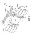
- Cutting assembly 40 generally forms strips 41 from sheet 21 for subsequent assembly of tire band 14. More specifically, cutting assembly 40 utilizes a plurality of cutting members 42 to cut strips 41, wherein each cutting member 42 includes a cutting edge 43. Cutting members 42 generally are spaced along a length of sheet 21, and along a circumference of cutting surface 50 and/or cutting drum 52. In the embodiment shown in the FIGURES, cutting members 42 are rotating knives. Rotating knives, in the embodiment shown, operate similarly to idler wheels, and freely rotate at the direction of the translating sheet 21. Still, rotating knives 42 may be driven by a motor or any other known driving means. Also, other means for cutting sheet 21 known to one of ordinary skill in the art may be used in lieu of rotating knives, including other non-rotating knives, blades, or edges.
- cutting members 42 translate laterally along a width of sheet 21 (i.e., in a sideways direction of sheet 21 ).
- Translation is achieved by translation members 44, each of which may comprise, without limitation, a linear actuator, a servo motor, a pneumatic or hydraulic cylinder, or any other translation means known to one of ordinary skill in the art.
- Translation members 44 generally translate along a linear translation axis 45, but it is also understood that non-linear translation may occur.
- a cutting member 42 may translate by way of translation member 44a, which is mounted to a side of sheet 21.
- cutting member translation may be achieve by translation member 44b, which translates about a rail 46 or the like that is mounted above sheet 21.
- Each cutting member 42 may also be capable of extending up and down from rail 46 by an extension member 47, which may comprise any means of extending, such as, for example, a servo, solenoid, cylinder, which may be pneumatic or hydraulic.
- Each cutting member 42 may also be capable of rotating in angled relation to the direction in which sheet 21 is translating, as shown in FIG. 7 . Such rotation may improve the ability of cutting member 42 to perform a transverse cut along a width of sheet, such as shown in FIG. 7 .
- Cutting member 42 may rotate at any angle in any direction.
- cutting member 42 rotates approximately 45 degrees from the translation direction (i.e., the direction of travel) of sheet 21. Rotation may be achieved by a rotation member 48, which may comprise an electromagnetic solenoid, or any other means of rotating a cutting member 42 that is known to one of ordinary skill in the art.
- Controller 90 generally controls the operation and movement of cutting members 42 by operation of translation members 44, extension members 47, and rotation members 48. Controller 90 may cooperate with a single or multi-axis motion controller to synchronize and coordinate the operation and movement of the cutting members 42.
- Cutting members 42 may operate along a cutting surface 50, upon which sheet 21 may rest during the cutting process.
- cutting surface is arcuate, such as when associated with a cutting drum 52.
- Cutting surface may also comprise a flat or planar cutting surface may be used.
- Cutting surface 50 may smooth or rough, such as is described in relation to applicator drum 62 to promote adhesion between cutting surface 50 and sheet 21, as well as with any resulting strip 41 formed there from.
- Such adhesion may also maintain sheet 21, as well as any resulting strips 41, in a desired position along surface 50, which may more accurately cut and transfer strips from the cutting assembly 40 and/or applicator assembly 60. Adhesion may also be promoted by maintaining contact with cutting surface 50 for a particular duration or distance. In one embodiment, sheet 21 contacts surface 50 for at least 50% of the surface length, that is, 180 degrees of the drum circumference. Still, desired adhesion may be achieved even though sheet 21 does not engage cutting surface 50 for at least 50% of its surface length. To achieve a desired contact length, roller 54 may be used to direct sheet 21 onto cutting surface 50 at a desired location.
- roller 54 may also apply a pressure upon sheet 21 as it is being applied to cutting surface 50 to facilitate adhesion between sheet 21 and cutting surface 50.
- This pressure may be achieved by utilizing a pressure member, such as, for example, a pneumatic or hydraulic cylinder or spring, to direct a force through roller 54, and upon sheet 21 and cutting surface 50.
- Other means of applying pressure upon sheet 21 known to one of ordinary skill in the art may be used, such as, for example, maintaining a gap between roller 54 and surface 50, where the gap is less than a thickness of sheet 21.
- roller 54, or at least an outer surface thereof may be formed of a compliant or flexible material, such as silicone or a gel-like material, for the purpose of providing a desired, and more uniform, pressure along a width of sheet 21.
- Translation of sheet 21 through cutting assembly 40 may be controlled.
- generator 20 is capable of operating at various speeds, which may be adjusted as desired.
- a motor 56 may be provided to drive cutting drum 54, and therefore, drive sheet 21 through cutting assembly 40 and/or to recovery assembly 70. Motor 56 may also direct strips 41 onto building drum 82, when cutting drum 52 is also operating as an applicator drum 62 of strip applicator assembly 60. The rotational speed of motor 56 may be adjusted to control the size (i.e., the thickness and/or width) of sheet 21.
- the rotational speed of motor 56 is synchronized with the speed of generator 20, so not to stretch or compress any sheet 21 departing generator 20, and/or operating within cutting assembly 40, applicator assembly 60, and/or recovery assembly 70.
- Motor 56 may be controlled by controller 90, so to coordinate the operation of cutting members 42 to cut strips 41 from a sheet 21 translating along cutting surface 50.
- cutting members 42 cut a path 58 along translating sheet 21 to form one or more strips 41.
- a pair of cutting members 42 cuts a closed-loop path 58 to form a strip 41, as shown generally in FIGS. 4-6 , and more specifically in FIGS. 7-8 .
- Path 58 circumscribes strip 41, and may comprise a leading edge 58a, a trailing edge 58b, and one or more side edges 58c.
- Leading edge 58a and trailing edge 58b, each of which form a beginning and end of strip 41, respectively, may also operate as a side edge 58c, such as when cutting a strip 41 comprising a tear-shape or a 4-sided diamond-shape.
- a pair of cutting members 42a, 42b is able to form a strip 41 within sheet 21 while sheet 21 is operating in a closed-loop path, where such pair is by being placed in a staggered arrangement along a length of the sheet 21.
- This staggered arrangement allows a downstream, or subsequent, cutting member 42b to cut a path that intersects a preceding path formed by the upstream, or preceding, cutting member 42a, as shown in FIGS. 6-8 .
- This intersection may be used to form a beginning and end of each strip 41, which refer to the leading and trailing edges 58a, 58b, respectively.
- Leading and/or trailing edges may be cut by an additional cutting member 42 that is dedicated to making either or both such cuts.
- Cutting members 42 may translate while cutting sides 58c, such as, for example, to adjust or taper ( i.e., increase or decrease) the width of strip 41, or to otherwise vary the shape and/or size of strip 41.
- One or more cutting members 42 may also cut slits 16 (discussed above with reference to FIG. 2 ) during or after the formation of strips 41.
- each cutting member 42a, 42b intersects to initialize cutting path 58 and leading edge 58a . Such intersection may be achieved by crossing the cutting paths of each cutting member 42a, 42b, although crossing paths is not necessary to achieve the intersection, as the path of either member 42a, 42b may simply extend from a cutting path generated by the other member 42a, 42b.
- each cutting member 42a, 42b extends in a lateral direction ( i.e., in a direction angled from the translation direction of sheet 21 or a direction along a width of sheet 21 ) to make a lateral cut.
- each cutting member 42a, 42b may orient its cutting edge 43 in a direction parallel to the translation direction of sheet 21 or may rotate its cutting edge 43 to be angled relative to the translation direction or the centerline of sheet 21, as represented by cutting member 42b in FIG. 7 .
- each cutting member 42a, 42b makes side cuts 58c, and eventually forms trailing edge 58b with a final intersection to complete the formation of strip 41.
- strips 41 may taper in width, in stepped fashion as shown, or in a gradual manner, which may be linear or arcuate. Other variations or means of forming strips 41 may exist.
- each portion of sheet 21 that remains continuous (i.e., attached to preceding and subsequent portions of sheet 21 ) with sheet 21 is referred to as segment 26.
- Each segment 26 extends between longitudinally-extending voids 18, the voids 18 corresponding to strips 41 cut from sheet 21.
- One or more strips 41 may be formed within the width of sheet 21, such that a pair of segments 26a extend along the lateral sides of sheet 21, as shown in FIGS. 4-8 .
- a segment 26b may be located intermediately (i.e., between sheet sides) along sheet 21, such as, for example, when two or more strips 41 are concurrently cut from sheet 21, as shown in FIGS. 4-6 .
- an intermediate segment 26b may exist with or without any side segment 26a.
- segment 26 may tear while translating about system 10, or while one or more strips 41 are separating from sheet 21. Any tear or discontinuity in a segment 26 may compromise the continuity of sheet 21. Therefore, any such segment 26 should be properly sized to withstand the strip-separating stresses, as well as other stresses associated with navigating through system 10.
- the size of a segment 26 may vary according to the material forming sheet 21 (as each sheet material may have different tear properties).
- the combined width of all segments 26 for any cross-section of sheet 21 is at least 20 mm. In another embodiment, also when sheet 21 is between 0.5-1.5 mm thick, the width of each such segment 26 is at least 10 mm wide.
- each side of sheet 21 remains uncut so to provide a segment 26a at each lateral side of a cut sheet 21, as shown in the FIGURES, where each such segment 26a is at least 20 mm wide, and any intermediate segment 26b (i.e., any segment 26 not located along a side of sheet 21 ) may comprise any width, such as, for example, not less than 5 mm wide.
- segments 26 may comprise widths greater or less than those disclosed above.
- Side segments 26a , or a portion thereof may also comprise a thickness that is greater than the remaining portions of sheet 21, for the purpose of resisting tearing during the operation of system 10.
- the thickened portions are formed by generator 20. Thickened portions may also exist in other locations along the width of sheet 21 as desired.
- system 10 also includes an applicator assembly 60 for applying one or more continuous strips 41 to a building surface to form a band 14.
- the one or more strips 41 are wound about the building surface to form the multi-layered band 14.
- Applicator assembly 60 includes an applicator drum 62 that transfers one or more strips 41 there from to building assembly 80.
- applicator drum 62 may be heated or cooled.
- applicator drum 62 is maintained at a temperature at least 10 degrees Celsius higher than the temperature of sheet 21 and/or any strips 41. In other embodiments, applicator drum 62 is maintained at approximately 70 degrees Celsius.
- the surface of applicator drum 62 may comprise a smooth surface, which may be a chromed or hot chromed surface, so to provide a smooth, capillary-like surface that may promote molecular bonding and/or may operate like a vacuum to facilitate retention of strips 41 thereon. Improved adhesion may also be provided by providing a rough surface, the rough surface providing increased surface area for improved contact area, and therefore, increased adhesion. Applicator drum 62 may also operate as the cutting drum 52. Further, the temperature controls and conditions, as well as the surface conditions and treatments discussed with regard to applicator drum 62 above may also be applied to cutting drum 52 to improve adhesion between drum 52 and sheet 21.
- applicator drum 62 translates toward a building surface for the purpose of transferring a strip 41 to the building surface.
- the strip is wound about the building surface to form a band 14.
- Building surface may initially comprise a contact surface 84 of a building drum 82 or a tire carcass 84 located on the building drum 82.
- Building drum 82 may comprise any drum, and may or may not be a drum used to build tire carcasses.
- the building surface for subsequent strips 41 may include at least a portion of the previously-applied strip 41, which may also be referred to as a band 14.
- applicator drum 62 translates towards a building surface to transfer a strip 41 thereto. More generally, a relative translation between applicator drum 62 and the building surface exists, as either or both may translate towards the other for the purpose of transferring a strip 41 to the building surface.
- the applicator drum 62 is located in a transfer position relative to the building surface, such that a strip 41 passing between applicator drum 62 and the building surface contacts the building surface. The contact may be enough to develop enough adhesion between the strip 41 and the building surface, or a pressure may be applied to the strip 41 as it passes between drum 62 and the building surface.
- Pressure roller 64 may be used to apply pressure to the strip 41 as it is being wound about the building surface. This pressure not only promotes adhesion for building and maintaining a band 14, but also may promote cohesion in the cured product and reduce any air trapped within band 14.
- Pressure roller 64 generally includes a variable or "bumpy" surface, which may comprise, for example, a toothed surface as shown in the FIGURES.
- applicator drum 62 translates from an initial (i.e., a home) position to a transfer position, as shown in FIG. 9a .
- Drum 62 may then remain in the transfer position for a temporary period, that is, until the strip 41 passes between drum 62 and the building surface, as shown in FIG. 9b .
- drum 62 may retract to a resting position as shown in FIG. 9c , which may or may not be the home position. It is understood that drum 62 may remain in the transfer position, which includes gradually retracting as the band 14 grows in diameter.
- the rotational velocity of the building surface increases as the outer diameter of band 14 increases.
- a constant rotational velocity between the building surface and the applicator drum 62 may be provided so that strip 41 may translate at a relatively constant velocity.
- the rotational velocity of the surface of applicator drum 62 and that of the building surface may be substantially the same.
- the rotational speed of building drum 82 may be decreased and/or the speed of applicator drum 62 may be increased to compensate for the increasing diameter of band 14.
- pressure roller 64 generally remains in pressurized contact with any strip 41 being applied to the building surface, and gradually retracts as the diameter of band 14 increases as generally shown in FIG.
- applicator drum 62 may translate and return to a desired position, which may be the home position, to provide adequate clearance for removal of band 14 (with or without a tire carcass 86, if existing) from building drum 82.
- Recovery assembly 70 generally receives sheet 21 that has translated through cutting assembly 40, for the purpose of directing the recovered sheet 21 back to generator 20 as input material, and thereby completing a closed-loop path within system 10.
- the recovered sheet 21 may or may not have been cut by cutting assembly 40, that is, one or more strips 41 may not have been removed there from, such as when system 10 is in an idle mode.
- recovery assembly 70 includes a transfer roller 72 and a transfer assembly 74.
- transfer roller 72 initially engages sheet 21 upon release from cutting assembly 40, and directs the recovered sheet 21 onto transfer assembly 74.
- transfer assembly 74 generally comprises a plurality of rollers 76 and a conveyor belt 78. In lieu of the roller and conveyor belt, other means of translating sheet 21 known to one of ordinary skill in the art may be used, which may include, for example, a series of rollers or drums.
- recovery assembly 70 may also include a material processing unit 79.
- Processing unit 79 generally controls the manner in which recovered sheets 21 are re-introduced into generator 20 as input material.
- Generator 20 may have difficulties processing sheet 21 in the form it is recovered. For example, extruders may have difficulty processing cold or thin input material.
- the width of generator input 22 may have certain width requirements for input material that would encourage manipulation of recovered sheet 21 to particular widths. For example, when using calenders, it may be desirous to input material substantially along a width of the calender, as localized input may not generate sheets 21 having a desired width.
- generator input 22 may be smaller than the width of recovered sheet 21. Issues may also arise in response to the amount of sheet 21 being recovered.
- processing unit 79 may heat, cool, compile, resize, reshape, and/or distribute desired amounts of sheet 21 as input material for generator 20. Processing unit 79 may also control the rate at which recovered sheet 21 is introduced as input material.
- processing unit 79 includes a pivotable conveyor, which is capable of pivoting back and forth to build-up sheet 21 as it is deposited for input into generator 20.
- processing unit 79 may comprise an extruder, a plurality of cutting members, rollers, drums, or any other means for heating, cooling, resizing, reshaping, and/or distributing recovered sheet 21 as input material for generator 20.
- Processing unit 79 may be in communication with controller 90, which may provide instructions for manipulating sheet 21 and/or supplying sheet 21 as input material 12b for generator 20. Controller 90 may obtain information about retrieved sheets 21, such as weight, shape, and width measurements. Scales, lasers, or other measuring means may also be included along transfer assembly 74 and/or processing unit 79 to obtain any desired information regarding recovered sheet 21.
- band 14 may be formed of multiple materials, such as is shown in FIG. 2 .
- band 14 when band 14 is a tread band, it may be desired to include a hidden or submerged tread layer to provide desired properties when the submerged material becomes exposed after at least a portion of the first material is worn.
- a tread may be built at a single station having a plurality of systems 10, or may be built at multiple stations. When being built in a single station, two or more systems 10 may be used, wherein, for example, one system 10 is located above another system 10.
- system 10 may include a programmable logic controller 90, or other device having a processor that can execute programmed instructions, such as, for example, a personal computer or main frame computer.
- System 10 may also include a user interface 98.
- Controller 90 generally receives input and/or instructions to control system 10 and the operation of each assembly thereof, which includes the generation and translation of sheet 21 through system 10, the cutting and application of strips 41, and the recovery and manipulation of recovered sheet 21 for regeneration.
- Controller 90 may include a logic processor 92 (which may be a microprocessor), a memory storage device 93, such as RAM (random access memory), ROM (read-only memory), PROM (programmable read-only memory), and at least one input/output (I/O) cable 94 for communicating with system 10.
- RAM random access memory
- ROM read-only memory
- PROM programmable read-only memory
- I/O input/output
- controller 90 may include an I/O slot 95 for housing an I/O card having I/O cable connector 96.
- An operator may utilize a user-interface 98 to provide input to, and/or to control or instruct the operation of, controller 90 and system 10, which includes performing each step and method associated with forming and translating a sheet 21, cutting strips 41 there from, and applying the strips 41 to a building surface for assembling a multi-layered band 14.
- User-interface 98 and controller 90 may communicate by way of I/O cable 96. It is also contemplated that wireless communications may exist between controller 90, user-interface 98, and system 10.
- controller 90 may be programmed by any known graphical or text language.
- Memory device 93 may comprise any commercially known storage device, such as such as hard disk drives, optical storage devices, flash memory, and the like.
- Processor 92 executes programmed instructions and may perform the instructions and any calculations and/or measurements useful for controlling system 10 and performing the methods and operations discussed herein.
- Memory storage device 93 also stores inputs, outputs, and other information, such as, the geometry and location of any drum 52, 62, 82 and cutting members 42, the desired speed of sheet 21 translation and formation.
- controller 90 may be in communication with an axis motion controller to coordinate the operation of cutting members 42 by way of translation members 44, extension members 47, and/or rotation members 48. Further, controller 90 may be in communication with each of the cutting drum 52, applicator drum 62, and/or building drum 82, and is therefore able to determine the rotational position of each such drum during rotation thereof.
Description
- This invention relates generally to methods for forming a layered tire component. More specifically, this invention relates to methods for generating strips of material and using the same to form a band comprising a layered tire component.
- Various processes exist for forming bands comprising tire components, such as, for example, tire treads. Such processes include a winding process in which strips of material are wound about a drum to build a band having a desired cross-sectional profile. During the winding process, one or more strips may be assembled laterally and/or radially along a lateral width of the drum to form the desired profile. Application of each strip includes initially placing the strip manually upon the drum, winding the strip about the drum as desired, and subsequently cutting the strip from a supply source when a sufficient quantity of strip has been applied. A subsequent strip may be applied, which generally requires manual attachment thereof to the drum. Application of a second strip may also require a substitution of material sources. The overall process provides a discontinuous, inefficient process, wherein interruptions arise when building a tire component band with subsequent strips. Therefore, it may be desired to provide a continuous process, where subsequent strips may be formed and applied automatically, without unnecessary interruption or delay.
- With regard to strip formation, in certain instances, the strips are cut from a sheet or similar form of material. Upon removal of the strips from the sheet, the remaining sheet portion is generally directed from the machine. Not only does this potentially amount to waste of material, but it also provides inefficiencies. For example, when a material source is exhausted, which may comprise a roll or input material for an extruder, the exhausted source must be replaced or replenished with a new source. Therefore, it may be desired to provide a process in which unused or discarded material is automatically reused by the process as input material for the material supply source, which produces sheets for subsequent strip formation.
-
US20030168152 discloses an open-looped method of forming a structural member of a tire for a vehicle including cutting strips from a long band of material using a single cutting member. The strips are cut to have a predetermined length and width and are transferred to a forming drum where the strips are to be applied at a later time to form a tire. -
EP1295707 discloses an open-looped method of transferring an assembly of tire components including an inner liner and toe guards from a false drum to a building drum. A vacuum pad and suction cups are employed to transfer the inner liner and toe guards to the false drum where the inner liner is placed first onto the false drum and the toe guards are placed second onto the false drum. The inner liner and toe guards are cut to a desired length and are then transferred to the building drum. -
US5820726 discloses an open-looped method of applying sheet-like materials onto a transfer drum and subsequently to a building drum. The transfer drum and the building drum operate separately from another. The transfer drum assembles a stacked assembly of sheet materials for application to the building drum via a conveyor, where the sheet-like materials are cut into a predetermined size before application to the building drum. -
US5030079 discloses an apparatus and method for forming a strip of elastomeric material which is extruded onto a rotating roller where it is initially shaped by a die plate and then finally shaped by a calender roll positioned downstream from the die plate and in close proximity to the surface of the roller providing a finishing gap for finally shaping the strip of elastomeric material. The method is a discontinuous, open-looped process as the calendared material is cut along one of the calender rolls, which are cylindrical, for the purpose of forming a sheet for storage and later use. - The present invention relates to a method of forming a multi-layered tire component as defined in claim 1.
- Preferred embodiments of the invention are defined in the dependent claims.
- The foregoing and other objects, features and advantages of the invention will be apparent from the following more detailed descriptions of particular embodiments of the invention, as illustrated in the accompanying drawing wherein like reference numbers represent like parts of the invention.
-
-
FIG. 1 is a side view of a multi-layered tire component-forming system, which can be employed in methods according to the invention. -
FIG. 2 is a cross-sectional view of a multi-layered band formed in accordance with an embodiment of the invention. -
FIG. 3 is a perspective view of a cutting assembly of the system shown inFIG. 1 . -
FIG. 4 is a perspective view of the cutting and application assemblies of the system shown inFIG. 1 . -
FIG. 5 is a top view of the cutting and application assemblies of the system shown inFIG. 1 , wherein said assemblies are shown forming strips from a sheet and applying the strips onto a building surface to form a band, according to a method of the invention. -
FIG. 6 is a top view of a sheet, showing cutting paths formed into a sheet from which strips have been formed and removed, according to a method of the invention. -
FIG. 7 is a top view of a sheet, showing the independent cut paths of each cutting member for cutting an exemplary strip from a sheet, according to a method of the invention. -
FIG. 8 is a top view of a sheet, showing the independent cut paths of each cutting member for cutting an exemplary strip from a sheet, according to a method of the invention. -
FIG. 9a is a side view of the forming system shown inFIG. 1 , showing a cutting/applicator drum in a strip transfer position after translating towards the building drum, as employed in methods according to the invention. -
FIG. 9b is a side view of the forming system shown inFIG. 9a , showing a strip attached to the building drum after initially translating between the cutting/applicator drum and the building drum, as employed in methods according to the invention. -
FIG. 9c is a side view of the forming system shown inFIG. 9b , showing the cutting/applicator drum retracting from a strip transfer position to a resting position, as employed in methods according to the invention. -
FIG. 9d is a side view of the forming system shown inFIG. 9c , showing the pressure roller retracting with the growth of the multi-layered band, as employed in methods according to the invention. -
FIG. 10 is a side view of an alternative multi-layered tire component-forming system, as employed in methods according to the invention. -
FIG. 11 is a perspective view of a programmable logic controller for use with the multi-layered tire component-generating system, as employed in methods according to the invention - Particular embodiments of the present invention provide methods for forming a multi-layered tire component for use on a tire carcass.
- Particular embodiments of the present invention include methods of forming a multi-layered tire component. A multi-layered tire component may comprise, for example, a tread, sub-tread, or cushion gum, and may be formed by winding one or more strips about a building surface to form a multi-layered band (i.e., a ring). The strips may be placed laterally across a width of the band (i.e., the tire component), and may be stacked or layered radially to form a plurality of layers. The band may be profiled by winding one or more strips at particular locations along a width of the band, where each strip has a width that is less than the width of the band. Particular embodiments of such methods may include the step of introducing input material into a sheet generator. Other steps may include forming a sheet from input material with the sheet generator. Input material, such as, for example, elastomeric material, is introduced into a sheet generator to form a sheet of the input material. The generator processes the input material to form a sheet having a width and a thickness. Input material may include new material as well as previously formed sheet that has been recovered and returned to the generator. The sheet generator may comprise any known means of forming a sheet of material, such as, for example, an extruder or a calender. An extruder generally accepts input material and subsequently heats and pushes the same through a die to form a sheet, the die having a desired size and shape associated with a cross-section of sheet. Sheet may also be formed to a desired size and shape by translating through one or more calenders. A generator may also include both an extruder and a calender to cooperatively generate a sheet.
- The methods may further include the step of mechanically translating the sheet about a closed-loop path, the path extending from the sheet generator and returning to the sheet generator for use as input material. In other embodiments, the methods include the step of translating a sheet of material along a translation path through a mechanical system. Once the sheet is formed by the generator, the sheet is translated in a lengthwise direction along a continuous path through a cutting assembly, where one or more strips may be formed and extracted from the sheet. Subsequent to translating through the cutting assembly, the sheet, which may or may not have been cut by the cutting assembly, returns to the generator for reuse as input material for continuous formation of the sheet. Accordingly, the return of the sheet to the generator completes the continuous, closed-loop path. By providing a closed-loop path, unused sheet is reused to continuously form the sheet or a new sheet. Further, the closed-loop path provides an automatic strip forming system, in which various strips may be continuously and subsequently formed. Still further, the continuous, closed-loop path allows the sheet to start, stop, and restart as desired during the process of forming the tire component.
- The methods may further include the step of providing a mechanical system, the system including a plurality of cutting members. The methods may also include the step of cutting one or more strips of material from the sheet. In other embodiments, methods may include the steps of cutting a first strip from the sheet with one or more of the plurality of cutting members, this step occurring during the step of translating, and cutting a second strip from the sheet subsequent to the step of cutting the first strip, this step occurring during the step of translating. Subsequent to forming the sheet, the sheet translates as described above and is cut to form one or more strips, each of which may be used to assemble and form a multi-layered tire component. Cutting of the sheet occurs after sheet generation and prior to the sheet being redirected back to the generator to regenerate the continuous sheet. The strips may be formed by a plurality of cutting members, each of which may comprise, for example, rotary knives (i.e., disks or the like that rotate along a surface that is being cut) and/or stationary knives (i.e., any non-rotating knife). The plurality of cutting members may form a portion of a mechanical assembly, as suggested above. Each of the cutting members may operate to cut a path within sheet.
- In one embodiment, a step of cutting may include the steps of cutting one or more laterally extending cutting paths into the sheet of material with one or more of the plurality of cutting members to form a leading edge of the strip, cutting a one or more side cutting paths extending from the leading edge to form a width of the strip, and cutting one or more laterally extending cutting paths from the side paths to form a trailing edge of the strip. Cutting members may cut a path within the continuous sheet, where the path forms a perimeter about a strip, to allow the extraction and removal of the strip from the sheet. By cutting a beginning and an end of a strip, and a portion between the beginning and end, the sheet is able to remain continuous and translate about a closed-loop path. Cutting may be performed on a cutting drum, upon which the sheet translates. In other embodiments, a step of cutting may include the steps of positioning a pair of cutting members relative to the sheet, wherein each of the cutting members are arranged in a spaced relation to the other along a length of the sheet, engaging one of the cutting members with the sheet to form a first cutting path, and engaging the other cutting member with the sheet to form a second cutting path, wherein the first and second paths intersect in a first instance at a first end of the strip and intersect in a second instance at a second end of the strip, the first and second cutting paths extending between the first and second strip ends in a spaced apart relationship. A pair of cutting members may operate cooperatively to form a strip from within a sheet, which may occur along an intermediate portion between the sides of the sheet. To achieve this, the cutting paths formed by each cutting member intersect at different instances to form a leading and trailing edge (i.e., a beginning and end of a strip).
- In particular embodiments, a step of cutting may include translating at least one of the cutting members in any direction angled from a translation direction of the sheet. In particular embodiments, the step of cutting may include providing a cutting edge of at least one of the one or more cutting members that is angled relative a translation direction of the sheet during the step of cutting. When a cutting member cuts a path along a sheet, the sheet is moving in a translation direction. Therefore, a longitudinal or lengthwise cut may be made by simply pressing and maintaining a cutting member against the moving sheet. In other words, a cut may be made in the direction of travel of the sheet may by maintaining a cutting member in a stationary position with a cutting edge thereof engaging the moving sheet. However, if a lateral cut is desired, that is, a cut at any angle from the translation direction of the sheet, cutting member translates in desired any lateral direction (that is, at any angled direction other than 0 and 180 degrees from the translation direction of the sheet). Further, a cutting member may rotate to angle its cutting edge relative to the sheet's direction of travel to better achieve the angled cut along the sheet. Cutting members are also capable of cutting strips having different and/or varying widths. The plurality of cutting members may also be capable of cutting multiple strips concurrently from the sheet at different locations along the sheet width.
- Ultimately, strips are removed from the sheet. To facilitate separation of any strip(s) from the sheet, it is understood that a minimal amount of material remains in the sheet to resist any forces arising during the extracting of strips from the sheet. Otherwise, the sheet may rip or tear during strip extraction, and compromise the continuous nature of the sheet. In one embodiment, material remains along each of the lateral sides of the sheet after strip formation, or, in other words, strips are formed between the sides of the sheet so to leave a desired amount of material along each side of the sheet. Still, one or more sides of the sheet may be cut from the sheet to form a portion of a strip, and one or more intermediate portions of sheet may remain with or without one or more sides of sheet.
- The methods may further include the step of mechanically applying the one or more strips to a building surface during the step of forming. In other embodiments, the methods may include the steps of mechanically applying the first strip to a building surface, this step occurring during the step of translating and mechanically applying the second strip to a building surface, this step occurring during the step of translating. After a strip is initially cut, the beginning or leading edge of the strip is translated towards a building surface, to which the strip will be automatically transferred and wound to form a layered tire component (i.e., a band). In one embodiment, the building surface is associated with a building drum, which may include an exterior surface of the building drum as well as a surface of any tire carcass (which may comprise, for example, a tire belt), strip, or tire component (i.e., band) located on the building drum. In particular embodiments, it may be desired to facilitate adhesion between each strip and the applicator drum, so to retain each strip upon applicator drum while the remaining sheet is removed from applicator drum for return to the generator. Accordingly, applicator drum may be temperature controlled (i.e., capable of being heated and/or cooled), and the surface thereof may be a smooth or textured surface to promote the desired adhesion. Once the strip is separated from the sheet, the strip is directed towards the building surface. In particular embodiments, mechanically applying a strip includes placing each strip into pressurized contact against the building surface by translating at least one of the building surface and an applicator drum toward the other. To achieve the pressurized contact, in particular embodiments, the applicator drum translates towards the building surface. However, the applicator drum may temporarily place the strip into pressurized contact, and therefore, in particular embodiments, the applicator drum retracts to a resting position after placing each of the strips into pressurized contact against the building surface. Each of the steps of cutting and applying may be achieved mechanically, and may be repeated to subsequently apply one or more strips to the tire component.
- When a continuous sheet operates along a closed-loop path, it is possible to vary the formation and translation rate of the sheet. By reducing or stopping the translation of sheet when not forming or applying any strips, the amount of sheet material that is recovered and reprocessed is reduced, which may extend the life of the sheet material. Accordingly, the methods may also include the steps of translating the sheet at a first speed during the step of mechanical applying the one or more strips and translating the sheet at a second speed when performing steps other than the steps of applying and forming one or more strips, the second speed being less than the first speed. In one embodiment, the first speed may be at least 80 meters per minute. In particular embodiments, the second speed is 2 meters per minute or less. Particular embodiments include the second speed being 0 meters per minute. The duration of the temporary pause in sheet generation and translation may be limited in time based upon the particular composition and type of generator being used. For example, if an extruder is being used to form the sheet, a particular period of standby or inactivity may be allowed before the input material contained within the extruder reaches a critical temperature, upon which the composition and its properties begin to deteriorate or change. Therefore, before reaching any critical temperature, either the material should be extruded or the extruder temperature reduced to avoid any degradation in the input material properties. Further, the first speed may be selected to form a tire component (i.e., a band) within a desired period of time, such as, for example, during a tire building process, where one or more process are being performed at one or more stations during the same period of time.
- It may also arise that when a tire component is complete, there may be a delay while the completed component is removed and another building drum or the like is returned for building a subsequent tire component. Accordingly, the methods may also include the steps of terminating the step of forming one or more strips after the tire component has been formed, while the sheet continues to translate about the closed-loop path in the step of translating and re-performing the step of forming one or more strips for forming a subsequent tire component. Likewise, the methods may include the steps of terminating the steps of forming one or more strips and translating the sheet about a closed-loop path after the tire component has been formed and re-performing the steps of translating a sheet about a closed-loop path and forming one or more strips, for forming a subsequent tire component.
- The methods may further include the step of mechanically redirecting the sheet for reuse as input material. Steps may also include returning the sheet to the generator as input material. As mentioned above, once strips are cut and removed from the sheet, the remaining sheet may be redirected for reuse as input material in the formation of subsequent sheet by the generator. By returning to be reformed (i.e., reprocessed) into a subsequent, uncut, or full-width sheet, the closed-loop path is completed. During its return, but before reintroduction and reformation, the recovered sheet may be processed. The processing may include resizing and/or reshaping the recovered sheet, which may include heating or cooling the recovered sheet prior to reintroduction. In one embodiment, the recovered sheet is cooled prior to being introduced into an extruder generator, so the recovered sheet does not adhere to the inside of the extruder. Processing may also control the rate at which the recovered sheet is reintroduced for sheet reformation. This may be desired, as varying amounts of sheet may be recovered, as the formation and application process may be performed at varying rates and may include the extracting of varying quantities and sizes of strip from the sheet.
- The methods described herein are used to form a band forming a multi-layered tire component. Illustrative examples of a multi-layered tire component-forming machine for use in practicing such methods is discussed in further detail below.
- A
system 10 for generating amulti-layered tire component 14 in accordance with the methods described herein is generally shown inFIG. 1 .System 10 generally operates to form amulti-layered tire component 14 by windingstrips 41 about a building surface. Becausetire component 14 is a wound product, it generally forms a band (i.e,, a ring).Component 14 is also referred to herein as a band. Also,system 10 generates asheet 21 from which thestrips 41 are formed, and, in particular embodiments, thesheet 21 remains continuous as it travels along a closed-loop path to and from asheet generator 20. Accordingly,system 10 automatically returns any unused sheet material for reuse bygenerator 20.System 10 generally formselastomeric tire components 14, such as, for example, tread, sub-tread, and cushion gum. In the embodiment shown inFIG. 2 ,multi-layered band 14 comprises a profiled tire tread band. -
Band 14 shown comprises a plurality oflayers 15, which may be formed from one ormore strips 41 wound about a building surface, which, in one embodiment, comprises a surface associated with abuilding drum 82. Eachband 14, and therefore, the one ormore strips 41, may be formed of one or more elastomeric materials or compounds. In one example, as shown inFIG. 2 , strips 41a, 41b, 41c, and 41d are formed of a first material, whilestrips band 14 may also comprise different layered and/or profiled arrangements. In the band shown inFIG. 2 , strips 41a, 41b, and 41c are wound about a building surface to form profiled portions ofband 14.Slits 16 may be formed in astrip 41, or a portion thereof, to provide a means of releasing air that may become trapped betweenlayers 15, as shown inFIG. 2 whenstrip 41d is laid overstrip 41e, which then forms a pocket of trappedair 17 betweenstrips Slits 16 may be formed by a cuttingmember 42 of cuttingassembly 40, in one embodiment, or by any other cutting means known to one of ordinary skill in the art.Slits 16 may be cut at a particular lateral location, and the location may be maintained (i.e., remain constant) for a length of theslit 16. The lateral location may also vary (i.e., translate laterally) over a length of theslit 16, which, in a particular embodiment, may form a spiral-like slit 16 when thestrip 41 is wound to form aband 14. - In an embodiment,
system 10 comprises asheet generator 20, a cuttingassembly 40, astrip applicator assembly 60, arecovery assembly 70, and aprogrammable logic controller 90.System 10 may also include aroller assembly 30 for directing asheet 21 fromgenerator 20 to cuttingassembly 40. -
Sheet generator 20 generally transforms input material 12 into asheet 21, which is ultimately cut intostrips 41 by cuttingassembly 40. With continued reference toFIG. 1 , input material 12 is received throughinlet 22, and may comprise new material 12a and/or previously used material 12b supplied byrecovery assembly 70. After receiving input material 12,generator 20 forms the input material by any known means intosheet 21, wheresheet 21 is formed to any desired width and thickness.Sheet 21 is expelled fromgenerator 20 by way ofoutlet 24. In one embodiment, as shown inFIG. 1 ,generator 20 comprises an extruder. Extruders generally push input material 12 through a die or head, such as by way of a screw. Any extruder known to one of ordinary skill in the art may be used bysystem 10.Generator 20 may also comprise a calender, in lieu of an extruder, which may comprise a pair of rollers positioned in close proximity to each other to form a gap or nip, through which input material 12 passes to from asheet 21. The resultingsheet 21 includes a width associated with the width of the calender nip. While an extruder and calender are capable of operating at similarly high speeds, a calender may not accelerate as quickly to attain a desired speed, as it may take more effort and time to accelerate the rotational inertia of the calender rolls. This may affect the start-up time ofsystem 10, as well as the responsiveness ofsystem 10 to restart after a temporary delay. An extruder, however, typically applies significantly more heat to the input material than a calender during processing, which negatively affects scorch and other properties and, therefore, reduces the reprocessing life of the material used insystem 10. An extruder may also perform more work upon the input material, with at least reduced the fluidity of the material during its lifetime, which again reduces the life of such material. - In another embodiment, as shown in
FIG. 10 , agenerator 120 is provided, which comprises acalender system 122. As mentioned above, a calender may be desired as it generally does not deteriorate the input material 12 as quickly as an extruder. In the embodiment shown, an extruder 124 operates to intermittently produce input material 12c, for the limited purpose of providing input material 12c tocalender system 122 as is necessary to supplement input material 12b for formingsheet 21. Material 12c is transported alongtransfer assembly 28 to calendersystem 122, where material 12c becomes input material forcalender system 122.Transfer assembly 28 may comprise a conveyor or any other known means of translating material 12, such as may be discussed below in conjunction withtransfer assembly 74. Extruder 124 may be replaced by a calender, or, in another embodiment, neither may exist and instead input material 12a is directly deposited intocalender system 122. -
Generator 120, orcalender system 122, at least includes a pair of calender rolls 122a, 122b, through which input material 12b, 12c passes to formsheet 21. Calender rolls 122a, 122b are closely positioned to form a gap there between, which is referred to as a nip (also discussed above). The size of the nip forms a thickness ofsheet 21. Therefore, the nip, or the distance betweenrolls 122a, 122b, may be varied to adjust a thickness ofsheet 21. Aftersheet 21 is exits rolls 122a, 122b,sheet 21 may pass through one or more additional pairs of calender rolls, such as, for example, pairs 122b, 122c and 122c, 122d, as shown inFIG. 10 . Assheet 21 passes through these additional pairs of rolls, the dimensions (thickness and width) ofsheet 21 may be further manipulated to achieve a desiredsheet 21. If additional manipulation is not desired, the nip of each subsequent pair of rolls, if existing, may be widened to avoid any additional processing. Regardless, thecalender system 122 forms a path that directssheet 21 to cuttingassembly 40 and may also operate as a tensioning system, in addition to, or in place of,roller assembly 30, which is discussed in greater detail below. - The cross-sectional dimensions (i.e., width and thickness) of
sheet 21 are generally controlled bygenerator 20 and/orcalender system 122. An extruder may utilize a die to control the cross-sectional dimensions of asheet 21. A calender, such as 122a, 122b, may control the thickness by adjusting the nip (as discussed above) and the width by adjusting internal side constraints. The cross-sectional dimensions ofsheet 21 may also be adjusted and/or controlled by regulating the translation speed and/or tension of sheet as it travels throughsystem 10. For example, one or more drums or rolls may be used to control the speed and/or tension ofsheet 21, which include, for example, agenerator output drum 25, calender rolls 122a, 122b, 122c, 122d, one or more tensioning rolls 32, a cuttingdrum 52, and/or an applicator drum 62.Sheet 21 may comprise any thickness, and, in one embodiment, the thickness ofsheet 21 is between 0.5 and 1.5 millimeters (mm). - If the thickness of
sheet 21 is too small,sheet 21 may tear while navigating the translation path ofsystem 10, during the cutting or application processes, or whensystem 10 is resuming formation ofsheet 21 bygenerator 20. Therefore, a minimum thickness may be desired, where such thickness may vary depending upon the sheet material and the conditions to whichsheet 21 is exposed. Further,sheet 21 may include certain areas of increased thickness, where the increase in thickness is designed to resist any tearing ofsheet 21 withinsystem 10. In one embodiment, the lateral sides ofsheet 21 may comprise a thickness greater than the intermediate portions ofsheet 21. Also,generator 20 may provide an intermittent increase in the cross-sectional thickness ofsheet 21adjacent generator 20 to prevent any tearing ofsheet 21 whensystem 10 resumes sheet generation. - In
various embodiments generator 20 is capable of producingsheet 21 at various speeds, ranging from zero (0) meters per minute (m/min), to 80 m/min and above. This allowssystem 10 to rapidly producesheet 21 during band formation, and to slow or temporarily halt sheet generation when desired. It is commonly known that over-processing and reheating of elastomeric material negatively affects fluidity, scorch, and other material properties. Therefore, when strips 41 are not being produced, or when there is otherwise a delay in the band forming process, sheet formation and translation throughsystem 10, may be temporarily placed in an idle mode or temporarily stopped. This may reduce any unnecessary re-processing of input material to extend the life thereof. When in idle mode,sheet 21 may translate, andgenerator 20 may operate, at an idle speed. The idle speed may be any desired speed, which may be, for example, 2 m/min. When it is desired to formband 14,system 10 may operate in a production mode, where strips 41 are formed and applied at any desired speed. When in production mode, in one embodiment, atleast generator 20, cuttingassembly 40, andapplicator assembly 60 operate at a production speed of 80 m/min. The production speed may vary, and may increase from an initial speed. For example, when in production mode, the production speed may be achieved by escalating from the idle speed. Production mode may also initialize from a ready mode, the ready mode having a ready mode speed that is greater than the idle speed and less than the production speed. In one embodiment, the ready mode speed is 20 m/min. When switching between modes, the speed may slowly or methodically ramp up or down in an effort to prevent any tearing ofsheet 21, which may result from abrupt changes in speed. As discussed above, particular portions ofsheet 21 may include thickened portions to resist any tearing ofsheet 21 on restart or the increase in operation speed. - As shown in
FIG. 1 , aroller assembly 30 may be located betweensheet generator 20 and cuttingassembly 40.Roller assembly 30 generally comprises one ormore rolls 32 arranged to form a translation path ofsheet 21. The particular translation path directssheet 21 to cuttingassembly 40, and may be used totense sheet 21 as desired. The location ofrolls 32 may be adjusted to impart more or less tension onsheet 21, which may also provide a means for adjusting the cross-sectional dimensions ofsheet 21. One ormore rolls 32 may be driven or powered, such as, for example, by a motor, to assist in the translation ofsheet 21, and/or adjustment of tension insheet 21.Sheet 21 may also be tensed by creating a speed differential betweendrum 25 and/or cuttingdrum 52, by increasing or decreasing the rotational speed of either drum. As stated above,calender system 122, as shown inFIG. 10 , may also operate as a tensioning system, as the sheet translates aboutrolls 122a-d. - Cutting
assembly 40 generally forms strips 41 fromsheet 21 for subsequent assembly oftire band 14. More specifically, cuttingassembly 40 utilizes a plurality of cuttingmembers 42 to cutstrips 41, wherein each cuttingmember 42 includes acutting edge 43. Cuttingmembers 42 generally are spaced along a length ofsheet 21, and along a circumference of cuttingsurface 50 and/or cuttingdrum 52. In the embodiment shown in the FIGURES, cuttingmembers 42 are rotating knives. Rotating knives, in the embodiment shown, operate similarly to idler wheels, and freely rotate at the direction of the translatingsheet 21. Still, rotatingknives 42 may be driven by a motor or any other known driving means. Also, other means for cuttingsheet 21 known to one of ordinary skill in the art may be used in lieu of rotating knives, including other non-rotating knives, blades, or edges. - To cut
strips 41 at desired locations alongsheet 21, cuttingmembers 42 translate laterally along a width of sheet 21 (i.e., in a sideways direction of sheet 21). Translation is achieved by translation members 44, each of which may comprise, without limitation, a linear actuator, a servo motor, a pneumatic or hydraulic cylinder, or any other translation means known to one of ordinary skill in the art. Translation members 44 generally translate along alinear translation axis 45, but it is also understood that non-linear translation may occur. In the embodiment shown inFIGS. 1 ,3-8 , a cuttingmember 42 may translate by way of translation member 44a, which is mounted to a side ofsheet 21. Also shown, cutting member translation may be achieve by translation member 44b, which translates about arail 46 or the like that is mounted abovesheet 21. Each cuttingmember 42 may also be capable of extending up and down fromrail 46 by an extension member 47, which may comprise any means of extending, such as, for example, a servo, solenoid, cylinder, which may be pneumatic or hydraulic. Each cuttingmember 42 may also be capable of rotating in angled relation to the direction in whichsheet 21 is translating, as shown inFIG. 7 . Such rotation may improve the ability of cuttingmember 42 to perform a transverse cut along a width of sheet, such as shown inFIG. 7 . Cuttingmember 42 may rotate at any angle in any direction. In one embodiment, cuttingmember 42 rotates approximately 45 degrees from the translation direction (i.e., the direction of travel) ofsheet 21. Rotation may be achieved by arotation member 48, which may comprise an electromagnetic solenoid, or any other means of rotating a cuttingmember 42 that is known to one of ordinary skill in the art.Controller 90 generally controls the operation and movement of cuttingmembers 42 by operation of translation members 44, extension members 47, androtation members 48.Controller 90 may cooperate with a single or multi-axis motion controller to synchronize and coordinate the operation and movement of the cuttingmembers 42. - Cutting
members 42 may operate along a cuttingsurface 50, upon whichsheet 21 may rest during the cutting process. In the embodiment ofFIG. 1 , cutting surface is arcuate, such as when associated with a cuttingdrum 52. Cutting surface may also comprise a flat or planar cutting surface may be used. Cuttingsurface 50 may smooth or rough, such as is described in relation to applicator drum 62 to promote adhesion between cuttingsurface 50 andsheet 21, as well as with any resultingstrip 41 formed there from. - When using cutting
drum 52, it is desirous to promote adhesion between cuttingsurface 50 andsheet 21. In addition to providing aparticular cutting surface 50, as described above, another means to promote adhesion is to heat or cool the cuttingsurface 50 ordrum 52. This adhesion promotes the separation ofstrips 41 fromsheet 21 by allowing anystrip 41 to remain adhered to cuttingdrum 52 and/or applicator drum 62 while thesheet 21 is lifted there from. Otherwise, anystrip 41 may continue with thesheet 21 intorecovery assembly 70. Of course, the adhesion is temporary as eachstrip 41 is ultimately removed and transferred to a building surface. Such adhesion may also maintainsheet 21, as well as any resultingstrips 41, in a desired position alongsurface 50, which may more accurately cut and transfer strips from the cuttingassembly 40 and/orapplicator assembly 60. Adhesion may also be promoted by maintaining contact with cuttingsurface 50 for a particular duration or distance. In one embodiment,sheet 21 contacts surface 50 for at least 50% of the surface length, that is, 180 degrees of the drum circumference. Still, desired adhesion may be achieved even thoughsheet 21 does not engage cuttingsurface 50 for at least 50% of its surface length. To achieve a desired contact length,roller 54 may be used todirect sheet 21 onto cuttingsurface 50 at a desired location. Of course, the amount of contact desired for asheet 21 may depend on the material used to formsheet 21, as well as the amount of heat present in cuttingsurface 50 ordrum 52.Roller 54 may also apply a pressure uponsheet 21 as it is being applied to cuttingsurface 50 to facilitate adhesion betweensheet 21 and cuttingsurface 50. This pressure may be achieved by utilizing a pressure member, such as, for example, a pneumatic or hydraulic cylinder or spring, to direct a force throughroller 54, and uponsheet 21 and cuttingsurface 50. Other means of applying pressure uponsheet 21 known to one of ordinary skill in the art may be used, such as, for example, maintaining a gap betweenroller 54 andsurface 50, where the gap is less than a thickness ofsheet 21. In one embodiment,roller 54, or at least an outer surface thereof, may be formed of a compliant or flexible material, such as silicone or a gel-like material, for the purpose of providing a desired, and more uniform, pressure along a width ofsheet 21. - Translation of
sheet 21 through cuttingassembly 40 may be controlled. As mentioned above,generator 20 is capable of operating at various speeds, which may be adjusted as desired. Further, with reference toFIG. 3 , amotor 56 may be provided to drive cuttingdrum 54, and therefore, drivesheet 21 through cuttingassembly 40 and/or torecovery assembly 70.Motor 56 may also directstrips 41 onto buildingdrum 82, when cuttingdrum 52 is also operating as an applicator drum 62 ofstrip applicator assembly 60. The rotational speed ofmotor 56 may be adjusted to control the size (i.e., the thickness and/or width) ofsheet 21. In one embodiment, the rotational speed ofmotor 56 is synchronized with the speed ofgenerator 20, so not to stretch or compress anysheet 21 departinggenerator 20, and/or operating within cuttingassembly 40,applicator assembly 60, and/orrecovery assembly 70.Motor 56 may be controlled bycontroller 90, so to coordinate the operation of cuttingmembers 42 to cutstrips 41 from asheet 21 translating along cuttingsurface 50. - In operation, cutting
members 42 cut apath 58 along translatingsheet 21 to form one or more strips 41. In one embodiment, a pair of cuttingmembers 42 cuts a closed-loop path 58 to form astrip 41, as shown generally inFIGS. 4-6 , and more specifically inFIGS. 7-8 .Path 58 circumscribesstrip 41, and may comprise aleading edge 58a, a trailingedge 58b, and one ormore side edges 58c. Leadingedge 58a and trailingedge 58b, each of which form a beginning and end ofstrip 41, respectively, may also operate as aside edge 58c, such as when cutting astrip 41 comprising a tear-shape or a 4-sided diamond-shape. In one embodiment, a pair of cuttingmembers strip 41 withinsheet 21 whilesheet 21 is operating in a closed-loop path, where such pair is by being placed in a staggered arrangement along a length of thesheet 21. This staggered arrangement allows a downstream, or subsequent, cuttingmember 42b to cut a path that intersects a preceding path formed by the upstream, or preceding, cuttingmember 42a, as shown inFIGS. 6-8 . This intersection may be used to form a beginning and end of eachstrip 41, which refer to the leading and trailingedges strip 41, respectively) may be cut by anadditional cutting member 42 that is dedicated to making either or both such cuts. Cuttingmembers 42 may translate while cuttingsides 58c, such as, for example, to adjust or taper (i.e., increase or decrease) the width ofstrip 41, or to otherwise vary the shape and/or size ofstrip 41. One ormore cutting members 42 may also cut slits 16 (discussed above with reference toFIG. 2 ) during or after the formation ofstrips 41. - In the sheets shown in
FIGS. 7-8 , cuttingmembers path 58 andleading edge 58a. Such intersection may be achieved by crossing the cutting paths of each cuttingmember member other member member sheet 21 or a direction along a width of sheet 21) to make a lateral cut. In making a lateral cut, each cuttingmember cutting edge 43 in a direction parallel to the translation direction ofsheet 21 or may rotate itscutting edge 43 to be angled relative to the translation direction or the centerline ofsheet 21, as represented by cuttingmember 42b inFIG. 7 . After reaching a desired lateral position, each cuttingmember side cuts 58c, and eventuallyforms trailing edge 58b with a final intersection to complete the formation ofstrip 41. As shown inFIG. 8 , strips 41 may taper in width, in stepped fashion as shown, or in a gradual manner, which may be linear or arcuate. Other variations or means of formingstrips 41 may exist. - Subsequent to the formation of one or
more strips 41, the remaining portion ofsheet 21 is directed torecovery assembly 70 for reuse bygenerator 20. To maintain acontinuous sheet 21 that automatically navigates throughsystem 10, a continuous portion ofsheet 21 remains after removal of one ormore strips 41 there from. With reference toFIGS. 4-8 , each portion ofsheet 21 that remains continuous (i.e., attached to preceding and subsequent portions of sheet 21) withsheet 21 is referred to as segment 26. Each segment 26 extends between longitudinally-extendingvoids 18, thevoids 18 corresponding tostrips 41 cut fromsheet 21. One ormore strips 41 may be formed within the width ofsheet 21, such that a pair of segments 26a extend along the lateral sides ofsheet 21, as shown inFIGS. 4-8 . It is also contemplated that a segment 26b may be located intermediately (i.e., between sheet sides) alongsheet 21, such as, for example, when two ormore strips 41 are concurrently cut fromsheet 21, as shown inFIGS. 4-6 . Finally, an intermediate segment 26b may exist with or without any side segment 26a. - If the cross-section of any such return segment 26 becomes too small, or, in other words, becomes too thin or too narrow, segment 26 may tear while translating about
system 10, or while one ormore strips 41 are separating fromsheet 21. Any tear or discontinuity in a segment 26 may compromise the continuity ofsheet 21. Therefore, any such segment 26 should be properly sized to withstand the strip-separating stresses, as well as other stresses associated with navigating throughsystem 10. Of course, the size of a segment 26 may vary according to the material forming sheet 21 (as each sheet material may have different tear properties). In one embodiment, whensheet 21 is between 0.5-1.5 mm thick, the combined width of all segments 26 for any cross-section of sheet 21 (i.e., along a transverse plane perpendicular to the translation direction (i.e., the direction of travel) of sheet 21) is at least 20 mm. In another embodiment, also whensheet 21 is between 0.5-1.5 mm thick, the width of each such segment 26 is at least 10 mm wide. In yet another embodiment, forsheets 21 between 0.5-1.5 mm thick, each side ofsheet 21 remains uncut so to provide a segment 26a at each lateral side of acut sheet 21, as shown in the FIGURES, where each such segment 26a is at least 20 mm wide, and any intermediate segment 26b (i.e., any segment 26 not located along a side of sheet 21) may comprise any width, such as, for example, not less than 5 mm wide. Because the composition of the sheet material may vary, as well as the sheet thickness and the stresses experienced during translation, segments 26 may comprise widths greater or less than those disclosed above. Side segments 26a, or a portion thereof, may also comprise a thickness that is greater than the remaining portions ofsheet 21, for the purpose of resisting tearing during the operation ofsystem 10. In one embodiment, the thickened portions are formed bygenerator 20. Thickened portions may also exist in other locations along the width ofsheet 21 as desired. - With general reference to
FIGS. 1 ,4-5 ,system 10 also includes anapplicator assembly 60 for applying one or morecontinuous strips 41 to a building surface to form aband 14. The one ormore strips 41 are wound about the building surface to form themulti-layered band 14.Applicator assembly 60 includes an applicator drum 62 that transfers one ormore strips 41 there from to buildingassembly 80. To provide adhesion between applicator drum 62 and strips 41, which promotes the separation ofstrips 41 fromsheet 21, applicator drum 62 may be heated or cooled. In particular embodiments, applicator drum 62 is maintained at a temperature at least 10 degrees Celsius higher than the temperature ofsheet 21 and/or anystrips 41. In other embodiments, applicator drum 62 is maintained at approximately 70 degrees Celsius. The surface of applicator drum 62 may comprise a smooth surface, which may be a chromed or hot chromed surface, so to provide a smooth, capillary-like surface that may promote molecular bonding and/or may operate like a vacuum to facilitate retention ofstrips 41 thereon. Improved adhesion may also be provided by providing a rough surface, the rough surface providing increased surface area for improved contact area, and therefore, increased adhesion. Applicator drum 62 may also operate as the cuttingdrum 52. Further, the temperature controls and conditions, as well as the surface conditions and treatments discussed with regard to applicator drum 62 above may also be applied to cuttingdrum 52 to improve adhesion betweendrum 52 andsheet 21. - As shown in
FIG. 9 , applicator drum 62 translates toward a building surface for the purpose of transferring astrip 41 to the building surface. Once an initial portion ofstrip 41 is transferred to the building surface, the strip is wound about the building surface to form aband 14. Building surface, for example, may initially comprise acontact surface 84 of abuilding drum 82 or atire carcass 84 located on thebuilding drum 82. Buildingdrum 82 may comprise any drum, and may or may not be a drum used to build tire carcasses. Once astrip 41 has been applied to the building surface, the building surface forsubsequent strips 41 may include at least a portion of the previously-appliedstrip 41, which may also be referred to as aband 14. - As mentioned above, applicator drum 62 translates towards a building surface to transfer a
strip 41 thereto. More generally, a relative translation between applicator drum 62 and the building surface exists, as either or both may translate towards the other for the purpose of transferring astrip 41 to the building surface. To transfer astrip 41 from applicator drum 62 to a building surface, the applicator drum 62 is located in a transfer position relative to the building surface, such that astrip 41 passing between applicator drum 62 and the building surface contacts the building surface. The contact may be enough to develop enough adhesion between thestrip 41 and the building surface, or a pressure may be applied to thestrip 41 as it passes between drum 62 and the building surface. This pressure may be achieved by locating drum 62 closer to building surface, so thatstrip 41 squeezes between drum 62 and the building surface. Additionally, apressure roller 64 may be used to apply pressure to thestrip 41 as it is being wound about the building surface. This pressure not only promotes adhesion for building and maintaining aband 14, but also may promote cohesion in the cured product and reduce any air trapped withinband 14.Pressure roller 64 generally includes a variable or "bumpy" surface, which may comprise, for example, a toothed surface as shown in the FIGURES. - In operation, according to one embodiment, applicator drum 62 translates from an initial (i.e., a home) position to a transfer position, as shown in
FIG. 9a . Drum 62 may then remain in the transfer position for a temporary period, that is, until thestrip 41 passes between drum 62 and the building surface, as shown inFIG. 9b . Subsequent to this temporary period, drum 62 may retract to a resting position as shown inFIG. 9c , which may or may not be the home position. It is understood that drum 62 may remain in the transfer position, which includes gradually retracting as theband 14 grows in diameter. During the transfer and winding process, the rotational velocity of the building surface (the outer surface of band 14) increases as the outer diameter ofband 14 increases. Because it may be desired to maintain the size, shape, and structural integrity ofstrips 41 during transfer and winding operations, a constant rotational velocity between the building surface and the applicator drum 62 may be provided so thatstrip 41 may translate at a relatively constant velocity. To achieve the constant velocities, the rotational velocity of the surface of applicator drum 62 and that of the building surface may be substantially the same. Further, during the winding process, the rotational speed of buildingdrum 82 may be decreased and/or the speed of applicator drum 62 may be increased to compensate for the increasing diameter ofband 14. Also, during the winding process,pressure roller 64 generally remains in pressurized contact with anystrip 41 being applied to the building surface, and gradually retracts as the diameter ofband 14 increases as generally shown inFIG. 9d , so not to damage anystrip 41 orband 14 during the winding process. Onceband 14 is complete, applicator drum 62 may translate and return to a desired position, which may be the home position, to provide adequate clearance for removal of band 14 (with or without a tire carcass 86, if existing) from buildingdrum 82. -
Recovery assembly 70 generally receivessheet 21 that has translated through cuttingassembly 40, for the purpose of directing the recoveredsheet 21 back togenerator 20 as input material, and thereby completing a closed-loop path withinsystem 10. The recoveredsheet 21 may or may not have been cut by cuttingassembly 40, that is, one ormore strips 41 may not have been removed there from, such as whensystem 10 is in an idle mode. In the embodiment ofFIG. 1 ,recovery assembly 70 includes atransfer roller 72 and atransfer assembly 74. In one embodiment,transfer roller 72 initially engagessheet 21 upon release from cuttingassembly 40, and directs the recoveredsheet 21 ontotransfer assembly 74. In one embodiment,transfer assembly 74 generally comprises a plurality ofrollers 76 and aconveyor belt 78. In lieu of the roller and conveyor belt, other means of translatingsheet 21 known to one of ordinary skill in the art may be used, which may include, for example, a series of rollers or drums. - As shown in
FIG. 1 ,recovery assembly 70 may also include amaterial processing unit 79. Processingunit 79 generally controls the manner in which recoveredsheets 21 are re-introduced intogenerator 20 as input material.Generator 20 may havedifficulties processing sheet 21 in the form it is recovered. For example, extruders may have difficulty processing cold or thin input material. Further, the width ofgenerator input 22 may have certain width requirements for input material that would encourage manipulation of recoveredsheet 21 to particular widths. For example, when using calenders, it may be desirous to input material substantially along a width of the calender, as localized input may not generatesheets 21 having a desired width. Also,generator input 22 may be smaller than the width of recoveredsheet 21. Issues may also arise in response to the amount ofsheet 21 being recovered. For example, a plurality ofstrips 41, or a relativelywide strip 41, may have been removed fromsheet 21 prior to recovery, which may leave a minimal remainder ofsheet 21 for recovery. Therefore, processingunit 79 may heat, cool, compile, resize, reshape, and/or distribute desired amounts ofsheet 21 as input material forgenerator 20. Processingunit 79 may also control the rate at which recoveredsheet 21 is introduced as input material. - In the system shown in
FIG. 1 , processingunit 79 includes a pivotable conveyor, which is capable of pivoting back and forth to build-up sheet 21 as it is deposited for input intogenerator 20. In other embodiments, processingunit 79 may comprise an extruder, a plurality of cutting members, rollers, drums, or any other means for heating, cooling, resizing, reshaping, and/or distributing recoveredsheet 21 as input material forgenerator 20. Processingunit 79 may be in communication withcontroller 90, which may provide instructions for manipulatingsheet 21 and/or supplyingsheet 21 as input material 12b forgenerator 20.Controller 90 may obtain information about retrievedsheets 21, such as weight, shape, and width measurements. Scales, lasers, or other measuring means may also be included alongtransfer assembly 74 and/orprocessing unit 79 to obtain any desired information regarding recoveredsheet 21. - As mentioned earlier, it may be desired to form a
band 14 formed of multiple materials, such as is shown inFIG. 2 . For example, whenband 14 is a tread band, it may be desired to include a hidden or submerged tread layer to provide desired properties when the submerged material becomes exposed after at least a portion of the first material is worn. To achieve thismulti-material band 14, a tread may be built at a single station having a plurality ofsystems 10, or may be built at multiple stations. When being built in a single station, two ormore systems 10 may be used, wherein, for example, onesystem 10 is located above anothersystem 10. - With reference to
FIG. 11 ,system 10 may include aprogrammable logic controller 90, or other device having a processor that can execute programmed instructions, such as, for example, a personal computer or main frame computer.System 10 may also include auser interface 98.Controller 90 generally receives input and/or instructions to controlsystem 10 and the operation of each assembly thereof, which includes the generation and translation ofsheet 21 throughsystem 10, the cutting and application ofstrips 41, and the recovery and manipulation of recoveredsheet 21 for regeneration.Controller 90 may include a logic processor 92 (which may be a microprocessor), amemory storage device 93, such as RAM (random access memory), ROM (read-only memory), PROM (programmable read-only memory), and at least one input/output (I/O)cable 94 for communicating withsystem 10. Further,controller 90 may include an I/O slot 95 for housing an I/O card having I/O cable connector 96. An operator may utilize a user-interface 98 to provide input to, and/or to control or instruct the operation of,controller 90 andsystem 10, which includes performing each step and method associated with forming and translating asheet 21, cutting strips 41 there from, and applying thestrips 41 to a building surface for assembling amulti-layered band 14. User-interface 98 andcontroller 90 may communicate by way of I/O cable 96. It is also contemplated that wireless communications may exist betweencontroller 90, user-interface 98, andsystem 10. Generally,controller 90 may be programmed by any known graphical or text language. Programmed instructions, data, input, and output may be stored in amemory storage device 93, which is accessible toprocessor 92.Memory device 93 may comprise any commercially known storage device, such as such as hard disk drives, optical storage devices, flash memory, and the like.Processor 92 executes programmed instructions and may perform the instructions and any calculations and/or measurements useful for controllingsystem 10 and performing the methods and operations discussed herein.Memory storage device 93 also stores inputs, outputs, and other information, such as, the geometry and location of anydrum members 42, the desired speed ofsheet 21 translation and formation. As stated earlier,controller 90 may be in communication with an axis motion controller to coordinate the operation of cuttingmembers 42 by way of translation members 44, extension members 47, and/orrotation members 48. Further,controller 90 may be in communication with each of the cuttingdrum 52, applicator drum 62, and/or buildingdrum 82, and is therefore able to determine the rotational position of each such drum during rotation thereof. - While this invention has been described with reference to particular embodiments thereof, it shall be understood that such description is by way of illustration and not by way of limitation. Accordingly, the scope and content of the invention are to be defined only by the terms of the appended claims.
Claims (15)
- A method of forming a multi-layered tire component, the method comprising the steps of:providing a mechanical system (10), the system (10) including a plurality of cutting members (42); and a sheet generator (20);introducing input material into a sheet generator (20);forming a sheet of material with the sheet generator (20);translating a sheet (21) of material along a translation path through the mechanical system (10); wherein the translation path is a closed-loop path extending from the sheet generator (20) and returning at least a portion of the sheet to the sheet generator (20) for use as input material; cutting one or more strips (41, 41a, 41b, 41c, 41d) from the sheet with one or more of the plurality of cutting members (42), this step occurring during the step of translating;mechanically applying the one or more strips (41, 41a - 41d) to a building surface on a building drum (82), this step occurring during the step of translating and after the step of cutting one or more strips has initiated;wherein the step of mechanically applying the one or more strips (41, 41a - 41 d) includes placing each of the strips (41, 41a - 41d) into pressurized contact against the building surface by translating at least one of the building surface and an applicator drum (62) toward the other to force the one or more strips (41, 41a - 41d) against the building surface.
- The method of claim 1, wherein placing each of the one or more strips (41, 41a - 41d) into pressurized contact against the building surface includes translating an applicator drum (62) towards the building surface for each step of mechanically applying.
- The method of claim 2, wherein one of the building surface and the applicator drum (62) retracts to a resting position after placing each of the one or more strips (41, 41a - 41d) into pressurized contact against the building surface such that the building surface is spaced from the applicator drum (62) by a distance greater than a thickness of the sheet material.
- The method of claim 1, wherein the step of cutting includes the following steps:cutting one or more laterally extending cutting paths into the sheet (21) of material with one or more of the plurality of cutting members (42) to form a leading edge of the strip (41, 41a - 41d);cutting a one or more side cutting paths extending from the leading edge to form a width of the strip;cutting one or more laterally extending cutting paths from the side paths to form a trailing edge of the strip.
- The method of claim 1, wherein the step of cutting includes the following steps:positioning a pair of cutting members (42) relative to the sheet (21), wherein each of the cutting members (42) are arranged in a spaced relation to the other along a length of the sheet (21);engaging one of the cutting members (42) with the sheet (21) to form a first cutting path;engaging the other cutting member (42) with the sheet (21) to form a second cutting path, wherein the first and second paths intersect in a first instance at a first end of the strip (41) and intersect in a second instance at a second end of the strip (41), the first and second cutting paths extending between the first and second strip ends in a spaced apart relationship.
- The method of claim 1, wherein a cutting edge of at least one of the one or more cutting members is angled relative a translation direction of the sheet during the step of cutting.
- The method of claim 1, wherein the building surface is a surface associated with a building drum (82).
- The method of claim 1, wherein the sheet (21) is an elastomeric material.
- The method of claim 1 further comprising the steps of:translating the sheet (21) at a first speed during the step of translating the sheet; the first speed comprising a production speed for forming the multi-layered component; and, translating the sheet at a second speed during the step of mechanically translating the sheet, the second speed being less than the production speed
- The method of claim 9, wherein the step of translating includes the steps of:translating the sheet (21) at a first speed during the step of mechanical applying the one or more strips; and,translating the sheet at a second speed when performing steps other than the steps of applying and forming one or more strips, the second speed being less than the first speed.
- The method of claim 10, wherein the first speed is at least 80 meters per minute.
- The method of claim 9 further including the steps of:terminating the step of cutting one or more strips after the tire component has been formed, wherein the sheet continues to translate about the closed-loop path in the step of translating; and,re-performing the step of cutting one or more strips for forming a subsequent tire component.
- The method of claim 9 further including the steps of:terminating the steps of cutting one or more strips and translating the sheet (21) about a closed-loop path after the tire component has been formed; and,re-performing the steps of translating a sheet about a closed-loop path and cutting one or more strips, for forming a subsequent tire component.
- The method of claim 9 further comprising:translating the sheet at a third speed during the step of mechanically translating the sheet (21), the third speed being less than the second speed.
- The method of claim 1, wherein one of the applicator drum (62) and the building drum (82) retract as the building component increases in thickness.
Applications Claiming Priority (1)
| Application Number | Priority Date | Filing Date | Title |
|---|---|---|---|
| PCT/US2008/061292 WO2009131578A1 (en) | 2008-04-23 | 2008-04-23 | Method and apparatus for forming a multi-layered tire component |
Publications (3)
| Publication Number | Publication Date |
|---|---|
| EP2296867A1 EP2296867A1 (en) | 2011-03-23 |
| EP2296867A4 EP2296867A4 (en) | 2012-07-04 |
| EP2296867B1 true EP2296867B1 (en) | 2015-05-27 |
Family
ID=41217096
Family Applications (1)
| Application Number | Title | Priority Date | Filing Date |
|---|---|---|---|
| EP08746673.6A Active EP2296867B1 (en) | 2008-04-23 | 2008-04-23 | Method of forming a multi-layered tire component |
Country Status (6)
| Country | Link |
|---|---|
| US (1) | US8980030B2 (en) |
| EP (1) | EP2296867B1 (en) |
| JP (1) | JP2011518693A (en) |
| CN (1) | CN102015273B (en) |
| BR (1) | BRPI0822588A2 (en) |
| WO (1) | WO2009131578A1 (en) |
Families Citing this family (27)
| Publication number | Priority date | Publication date | Assignee | Title |
|---|---|---|---|---|
| JP5366716B2 (en) * | 2009-08-26 | 2013-12-11 | 株式会社ブリヂストン | Pneumatic tire manufacturing method |
| EP2563577B1 (en) | 2010-04-26 | 2015-03-11 | Pirelli Tyre S.p.A. | Method and apparatus for controlling the deposition of a continuous elongated element in building a tyre for vehicle wheels |
| FR2964591B1 (en) | 2010-09-10 | 2014-02-14 | Michelin Soc Tech | METHOD FOR MANUFACTURING PNEUMATIC BRAKE USING A BANDLET |
| FR2968592B1 (en) | 2010-12-13 | 2013-01-11 | Michelin Soc Tech | METHOD FOR MANUFACTURING PNEUMATIC BLANK USING A TABLECLOTH COMPRISING TWO GUMES |
| RU2596769C2 (en) * | 2011-05-31 | 2016-09-10 | Пирелли Тайр С.П.А. | Method and device for producing tires |
| NL2007058C2 (en) * | 2011-07-06 | 2013-01-08 | Vmi Holland Bv | COMPOSITION AND METHOD FOR MANUFACTURING A GREEN BAND |
| RU2556773C1 (en) | 2011-07-14 | 2015-07-20 | Мишлен Решерш Э Текник, С.А. | Tire with aggressive tread with perfected uniformity and wear resistance and method of its protection |
| CN103635307B (en) * | 2011-07-14 | 2017-06-20 | 米其林集团总公司 | For improving the uniformity of radical tread design and the method for durability and tire |
| EP2855171A4 (en) * | 2012-05-25 | 2016-01-13 | Michelin & Cie | Method and tire for improved uniformity and endurance of aggressive tread designs using layering technique |
| CN104540663B (en) * | 2012-07-31 | 2016-10-12 | 米其林集团总公司 | The automatic of calendering driving means for elastomer blends starts and continuous operation |
| US9073247B2 (en) * | 2012-07-31 | 2015-07-07 | Michelin Recherche Et Technique S.A. | Biasing wedge for use with calendering drives processing elastomeric mixes |
| US9028241B2 (en) | 2012-07-31 | 2015-05-12 | Michelin Recherche Et Technique S.A. | Stripper roll for use with calendering drives processing elastomeric mixes |
| FR3020018B1 (en) | 2014-04-18 | 2016-05-06 | Michelin & Cie | TIRE TREAD FOR A VEHICLE FOR AGRICULTURAL USE |
| US20170050398A1 (en) * | 2014-05-01 | 2017-02-23 | Compagnie Generale Des Etablissements Michelin | Method of tire tread production and tire produced thereby |
| FR3020990B1 (en) | 2014-05-13 | 2016-12-09 | Michelin & Cie | TIRE TREAD FOR A VEHICLE FOR AGRICULTURAL USE |
| US20200269534A1 (en) * | 2015-12-30 | 2020-08-27 | Bridgestone Americas Tire Operations, Llc | Tire with pre-formed ribbon tread and method of making same |
| IT201600096381A1 (en) * | 2016-09-26 | 2018-03-26 | Bridgestone Europe N V | MANUFACTURING METHOD OF A TIRE TREAD |
| JP6862833B2 (en) * | 2017-01-05 | 2021-04-21 | 住友ゴム工業株式会社 | Strip winding device |
| NL2018959B1 (en) * | 2017-05-22 | 2018-12-04 | Vmi Holland Bv | Method and assembly for applying a tire component to a drum |
| US10960626B2 (en) * | 2017-06-05 | 2021-03-30 | Bridgestone Americas Tire Operations, Llc | Bidirectional tire stitching wheel |
| JP6566084B1 (en) * | 2018-05-17 | 2019-08-28 | 横浜ゴム株式会社 | Apparatus and method for supplying rubber sheet member |
| US11554606B2 (en) | 2018-07-19 | 2023-01-17 | Gacw Incorporated | Off-highway vehicle including frame coupled gas spring wheel assemblies |
| US11590795B2 (en) | 2018-07-19 | 2023-02-28 | Gacw Incorporated | Wheel assembly including sidewall cover assembly and related methods |
| JP7091828B2 (en) * | 2018-05-22 | 2022-06-28 | 住友ゴム工業株式会社 | A device for forming rubber members for tires |
| CN108819022A (en) * | 2018-07-02 | 2018-11-16 | 联亚智能科技(苏州)有限公司 | A kind of rubber components winding system with material recycle function |
| US11565552B2 (en) * | 2018-07-19 | 2023-01-31 | Gacw Incorporated | Wheel assembly including spaced apart tread members having stacked rubber and reinforcing layers and related methods |
| US11173744B2 (en) | 2018-07-19 | 2021-11-16 | Gacw Incorporated | Wheel assembly including disk defining a mechanical stop and related methods |
Family Cites Families (77)
| Publication number | Priority date | Publication date | Assignee | Title |
|---|---|---|---|---|
| US1548156A (en) * | 1923-10-22 | 1925-08-04 | Kelly Springfield Tire Company | Tire-building machine |
| US2712852A (en) * | 1951-07-21 | 1955-07-12 | Black Clawson Co | Cutter unit for slitting machines |
| US3251722A (en) * | 1962-05-01 | 1966-05-17 | Voit Rubber Corp | Method of automatically applying a variable thickness elastomeric layer on pneumatic tire casings |
| GB1016279A (en) | 1963-10-15 | 1966-01-05 | Firestone Tire & Rubber Co | Method and apparatus for applying unvulcanized rubber material to a vehicle tire carcass |
| CH444473A (en) * | 1965-03-09 | 1967-09-30 | Firestone Prod | Device for separating fabric or film webs for the manufacture of vehicle tires |
| FR1560244A (en) * | 1967-03-29 | 1969-03-21 | ||
| US3580781A (en) * | 1968-05-20 | 1971-05-25 | Firestone Tire & Rubber Co | Apparatus for building up tread material on a tire carcass |
| US3607557A (en) * | 1969-06-11 | 1971-09-21 | Goodyear Tire & Rubber | Machine for forming and winding tread material on a tire |
| US3607556A (en) * | 1969-06-11 | 1971-09-21 | Goodyear Tire & Rubber | Tire building machine including an elastomer conveyor |
| US3779834A (en) * | 1971-06-21 | 1973-12-18 | Goodyear Tire & Rubber | Tire building machine |
| US3855030A (en) * | 1972-04-12 | 1974-12-17 | Vakuum Vulk Holdings Ltd | Method and apparatus for applying a tread strip to a carcass |
| JPS522435B2 (en) | 1972-12-09 | 1977-01-21 | ||
| SE404896B (en) * | 1977-04-05 | 1978-11-06 | Stabil Mek Verk | DEVICE FOR APPLYING A BAND-SHAPED MATERIAL ON THE SIDE OF A ROTATING SYMMETRIC BODY |
| DE2740609C2 (en) * | 1977-09-09 | 1982-05-13 | Continental Gummi-Werke Ag, 3000 Hannover | Device for building pneumatic tires or their parts |
| US4266112A (en) * | 1979-02-14 | 1981-05-05 | Niedermeyer William P | Web-cutting process |
| US4358978A (en) * | 1979-06-26 | 1982-11-16 | The Head Wrightson Machine Co. Ltd. | Trimming strip material |
| US4276104A (en) * | 1980-01-11 | 1981-06-30 | The Goodyear Tire & Rubber Company | Transfer drum application of narrow strip components to a tire being built on a tire building drum |
| DE3232162C2 (en) * | 1981-08-31 | 1986-01-23 | Sumitomo Rubber Industries Ltd., Kobe, Hyogo | Device for applying tire material |
| JPS5845042A (en) * | 1981-09-09 | 1983-03-16 | Sumitomo Rubber Ind Ltd | Apparatus for sticking rubber sheet on molding drum |
| JPH0635160B2 (en) | 1985-04-04 | 1994-05-11 | 株式会社ブリヂストン | Large tire molding method |
| SU1369916A1 (en) | 1986-05-11 | 1988-01-30 | Всесоюзный Научно-Исследовательский И Конструкторский Институт По Оборудованию Для Шинной Промышленности | Arrangement for placing side member blanks on assembly drum |
| SU1431960A1 (en) | 1987-01-19 | 1988-10-23 | Предприятие П/Я А-7310 | Arrangement for placing band material on assembly drum |
| DE3737676C1 (en) * | 1987-11-06 | 1989-01-26 | Berstorff Gmbh Masch Hermann | Process and plant for the production of tread strips consisting of more than one rubber component for treads of car tires |
| GB8809647D0 (en) * | 1988-04-23 | 1988-05-25 | Apsley Metals Ltd | Method of manufacture of tyre & apparatus therefor |
| GB8809646D0 (en) | 1988-04-23 | 1988-05-25 | Apsley Metals Ltd | Apparatus for manufacture of pneumatic tyre |
| JPH0517230Y2 (en) | 1989-08-31 | 1993-05-10 | ||
| US5030079A (en) * | 1989-10-27 | 1991-07-09 | The Goodyear Tire & Rubber Company | Roller die extrusion and calendering apparatus |
| JPH03187729A (en) | 1989-11-20 | 1991-08-15 | Bridgestone Corp | Apparatus for adhering tire constituting member |
| SU1705118A1 (en) | 1989-12-07 | 1992-01-15 | Научно-исследовательский институт шинной промышленности | Device for applying strip material to tyre-building drum |
| JPH0635970Y2 (en) | 1990-06-07 | 1994-09-21 | 山武ハネウエル株式会社 | Packaging equipment |
| DE4103232A1 (en) * | 1991-02-02 | 1992-08-06 | Continental Ag | VEHICLE AIR TIRE AND METHOD FOR THE PRODUCTION THEREOF |
| JPH0747617A (en) | 1993-08-06 | 1995-02-21 | Bridgestone Corp | Pneumatic tire, and production thereof |
| US5667610A (en) * | 1994-11-30 | 1997-09-16 | The Yokohama Rubber Co., Ltd. | Method of supplying sheet materials |
| JPH08216290A (en) | 1995-02-16 | 1996-08-27 | Bridgestone Corp | Manufacture of pneumatic tire |
| JPH0929856A (en) | 1995-07-14 | 1997-02-04 | Bridgestone Corp | Manufacture of tire |
| US6336488B1 (en) | 1995-12-15 | 2002-01-08 | The Goodyear Tire & Rubber Company | Unvulcanized noncord reinforced subassembly for incorporation in a tire casing |
| DE19816849C2 (en) * | 1998-04-16 | 2001-06-13 | Continental Ag | Process for manufacturing a pneumatic vehicle tire |
| DE19823433C1 (en) | 1998-05-26 | 1999-06-17 | Continental Ag | Application of thin rubber strip to partially vulcanised tire carcass |
| DE19831747A1 (en) * | 1998-07-15 | 2000-01-20 | Continental Ag | Building vehicle tire by winding-on strips of rubber for sidewalls, tread and belt reinforcements employs continuous extrusion with forming rolls, enabling two-stage vulcanization and incorporation of antistatic structure |
| JP2000108222A (en) | 1998-10-01 | 2000-04-18 | Yokohama Rubber Co Ltd:The | Strip winding molding machine |
| DE19900986A1 (en) * | 1999-01-13 | 2000-07-20 | Voith Sulzer Papiertech Patent | Transfer leader strip at a paper web is cut by controlled cutters to give cutting lines forming a pointed leading end and parallel sides for a simple and trouble-free web transfer to a target zone at the papermaking machine |
| JP4308978B2 (en) * | 1999-06-17 | 2009-08-05 | 横浜ゴム株式会社 | Heavy duty pneumatic radial tire |
| JP4259704B2 (en) * | 1999-12-07 | 2009-04-30 | 横浜ゴム株式会社 | Tire molding system and molding method |
| US6364981B1 (en) * | 1999-12-14 | 2002-04-02 | The Goodyear Tire & Rubber Company | Forming and application of tire ply |
| JP2001179848A (en) | 1999-12-27 | 2001-07-03 | Toyo Tire & Rubber Co Ltd | Method for manufacturing pneumatic tire and pneumatic tire |
| JP2001179849A (en) | 1999-12-28 | 2001-07-03 | Bridgestone Corp | Apparatus and method for manufacturing pneumatic tire |
| JP5013636B2 (en) | 2000-05-24 | 2012-08-29 | 株式会社ブリヂストン | Method for forming tire constituent member |
| JP4502579B2 (en) * | 2001-01-12 | 2010-07-14 | 株式会社ブリヂストン | Method and apparatus for manufacturing tire component |
| JP2002240164A (en) | 2001-02-20 | 2002-08-28 | Bridgestone Corp | Method and device for building tire |
| JP2002347135A (en) | 2001-05-29 | 2002-12-04 | Bridgestone Corp | Tire manufacturing method |
| WO2002102579A1 (en) | 2001-06-19 | 2002-12-27 | Bridgestone Corporation | Method of forming tire component member |
| JP2003080615A (en) * | 2001-09-10 | 2003-03-19 | Sumitomo Rubber Ind Ltd | Studless tire and method for manufacturing the same |
| US6736932B2 (en) * | 2001-09-14 | 2004-05-18 | The Goodyear Tire & Rubber Company | Cutting segment for a false drum |
| US6866736B2 (en) | 2001-09-21 | 2005-03-15 | The Goodyear Tire & Rubber Company | Combined transfer of toe guards and inner liner from false drum to building drum |
| WO2003070453A1 (en) * | 2002-02-22 | 2003-08-28 | Bridgestone Corporation | Thin rubber member producing method, rubber rolling device, and rubber rolling method |
| JP4244279B2 (en) * | 2002-03-06 | 2009-03-25 | 株式会社ブリヂストン | Rubber sheet manufacturing method |
| JPWO2004011236A1 (en) | 2002-07-25 | 2005-11-24 | 株式会社ブリヂストン | Tire component pasting device |
| US7622013B2 (en) | 2002-10-23 | 2009-11-24 | Bridgestone Corporation | Tire manufacturing method, cover rubber stamping device used therefore, tire, as well as rubber sheet member stamping method, and device |
| US7052568B2 (en) * | 2002-10-28 | 2006-05-30 | Bridgestone Firestone North American Tire, Llc | Tire retreading method |
| DE10333046A1 (en) * | 2003-07-18 | 2005-02-03 | Mitex Gummifabrik Hans Knott Gmbh | Process and apparatus for coating rolls |
| JP4136864B2 (en) * | 2003-09-19 | 2008-08-20 | 富士フイルム株式会社 | Web rewinding apparatus and method |
| US7195047B2 (en) * | 2003-12-11 | 2007-03-27 | The Goodyear Tire And Rubber Company | Tire manufacturing module and method of manufacturing tires |
| US7175726B2 (en) * | 2004-02-25 | 2007-02-13 | Toyo Tire & Rubber Co., Ltd. | Continuous rubber-strip forming apparatus and process |
| JP4639659B2 (en) | 2004-06-23 | 2011-02-23 | セイコーエプソン株式会社 | Electro-optical device substrate, electro-optical device, and electronic apparatus |
| DE602005004838T2 (en) | 2004-06-28 | 2009-02-12 | Sumitomo Rubber Industries Ltd., Kobe | A method of making a tread blank and pneumatic tires made with the tread blank |
| JP2006007661A (en) | 2004-06-28 | 2006-01-12 | Sumitomo Rubber Ind Ltd | Method for forming green tread rubber and pneumatic tire using green tread rubber formed by the method |
| JP2006051711A (en) | 2004-08-12 | 2006-02-23 | Sumitomo Rubber Ind Ltd | Method for producing rubber member for tire |
| JP4523815B2 (en) * | 2004-08-26 | 2010-08-11 | 住友ゴム工業株式会社 | Heavy duty pneumatic tire and manufacturing method thereof |
| JP2006069121A (en) | 2004-09-03 | 2006-03-16 | Bridgestone Corp | Pneumatic tire and its manufacturing method |
| JP2006110856A (en) * | 2004-10-14 | 2006-04-27 | Sumitomo Rubber Ind Ltd | Rubber strip sticking device |
| JP4532549B2 (en) | 2005-07-15 | 2010-08-25 | 東洋ゴム工業株式会社 | Carcass ply manufacturing method |
| DE102005046115A1 (en) | 2005-09-27 | 2007-03-29 | Continental Aktiengesellschaft | Apparatus for supplying and pressing rubber tapes or strips onto tire layer construction drum, includes frame-mounted rubber profiling device and endless rotating carrier for transporting the shaped material |
| JP2007098626A (en) * | 2005-09-30 | 2007-04-19 | Yokohama Rubber Co Ltd:The | Reinforcing member for tire and its production method |
| JP2007185886A (en) | 2006-01-13 | 2007-07-26 | Yokohama Rubber Co Ltd:The | Pasting-up method of tire constituent member by means of tire molding drum |
| JP2007283998A (en) * | 2006-04-20 | 2007-11-01 | Bridgestone Corp | Pneumatic tire, and method for manufacturing the same |
| DE102006033987A1 (en) * | 2006-07-22 | 2008-01-24 | Continental Aktiengesellschaft | feeder assembly |
| FR2914581B1 (en) | 2007-04-05 | 2009-07-03 | Michelin Soc Tech | DEVICE, INSTALLATION AND METHOD FOR APPLYING A GUM BAND TO A PNEUMATIC BRAKE. |
-
2008
- 2008-04-23 JP JP2011506248A patent/JP2011518693A/en active Pending
- 2008-04-23 US US12/989,335 patent/US8980030B2/en not_active Expired - Fee Related
- 2008-04-23 WO PCT/US2008/061292 patent/WO2009131578A1/en active Application Filing
- 2008-04-23 CN CN200880128794.2A patent/CN102015273B/en active Active
- 2008-04-23 EP EP08746673.6A patent/EP2296867B1/en active Active
- 2008-04-23 BR BRPI0822588A patent/BRPI0822588A2/en not_active IP Right Cessation
Also Published As
| Publication number | Publication date |
|---|---|
| EP2296867A4 (en) | 2012-07-04 |
| US20110036485A1 (en) | 2011-02-17 |
| CN102015273B (en) | 2015-05-27 |
| JP2011518693A (en) | 2011-06-30 |
| WO2009131578A1 (en) | 2009-10-29 |
| CN102015273A (en) | 2011-04-13 |
| BRPI0822588A2 (en) | 2019-03-06 |
| US8980030B2 (en) | 2015-03-17 |
| EP2296867A1 (en) | 2011-03-23 |
Similar Documents
| Publication | Publication Date | Title |
|---|---|---|
| EP2296867B1 (en) | Method of forming a multi-layered tire component | |
| EP2365904B1 (en) | Method and apparatus for forming a tire component upon an axially tapered surface | |
| CA2346429C (en) | A roll forming machine and method | |
| CA2115496C (en) | Method and machine for producing logs of web material and tearing the web upon completion of the winding of each log | |
| EP1833746B1 (en) | Apparatus for splicing a web material | |
| US20180186593A1 (en) | Single transfer insert placement method and apparatus | |
| NZ203362A (en) | Rolling closure strip onto molten extruded plastics film | |
| EP1642694A1 (en) | Method and apparatus for cutting elastomeric materials | |
| JP5058267B2 (en) | Method and apparatus for manufacturing pneumatic tires | |
| EP2855171A1 (en) | Method and tire for improved uniformity and endurance of aggressive tread designs using layering technique | |
| EP2659868B1 (en) | Single transfer insert placement method and apparatus | |
| RU2455166C1 (en) | Method and device for making tire multilayer component | |
| WO2004062897A1 (en) | Method and apparatus for producing constituent member of tire | |
| EP1279485B1 (en) | Method of producing a pneumatic tire having a reinforcement cord layer | |
| CN107708981B (en) | Extended ply laying process and system and apparatus therefor | |
| US1942398A (en) | Apparatus for producing embossed articles from plastic strip material | |
| US20170320262A1 (en) | Method and apparatus for manufacturing an embossed sanding sponge | |
| JP2001232695A (en) | Method for molding unvulcanized tire belt | |
| US3246352A (en) | Sole cutting apparatus | |
| CN114761219A (en) | Splicing matching forming machine | |
| JP3851347B2 (en) | Retrending device | |
| JPS63276543A (en) | Method and apparatus for laminating striplike material | |
| JP2002326245A (en) | Unvulcanized rubber sheet manufacturing method and manufacturing apparatus using the same | |
| IT202100022814A1 (en) | CORE EXCHANGE GROUP IN WINDING MACHINES | |
| JP2003136615A (en) | Method and apparatus for manufacturing paper tube |
Legal Events
| Date | Code | Title | Description |
|---|---|---|---|
| PUAI | Public reference made under article 153(3) epc to a published international application that has entered the european phase |
Free format text: ORIGINAL CODE: 0009012 |
|
| 17P | Request for examination filed |
Effective date: 20101111 |
|
| AK | Designated contracting states |
Kind code of ref document: A1 Designated state(s): AT BE BG CH CY CZ DE DK EE ES FI FR GB GR HR HU IE IS IT LI LT LU LV MC MT NL NO PL PT RO SE SI SK TR |
|
| AX | Request for extension of the european patent |
Extension state: AL BA MK RS |
|
| DAX | Request for extension of the european patent (deleted) | ||
| A4 | Supplementary search report drawn up and despatched |
Effective date: 20120604 |
|
| RIC1 | Information provided on ipc code assigned before grant |
Ipc: B29K 21/00 20060101ALI20120529BHEP Ipc: B29D 30/38 20060101AFI20120529BHEP Ipc: B29D 30/08 20060101ALI20120529BHEP Ipc: B29B 17/00 20060101ALI20120529BHEP |
|
| RAP1 | Party data changed (applicant data changed or rights of an application transferred) |
Owner name: MICHELIN RECHERCHE ET TECHNIQUE S.A. Owner name: COMPAGNIE GENERALE DES ETABLISSEMENTS MICHELIN |
|
| 17Q | First examination report despatched |
Effective date: 20131030 |
|
| GRAP | Despatch of communication of intention to grant a patent |
Free format text: ORIGINAL CODE: EPIDOSNIGR1 |
|
| INTG | Intention to grant announced |
Effective date: 20141218 |
|
| GRAS | Grant fee paid |
Free format text: ORIGINAL CODE: EPIDOSNIGR3 |
|
| GRAA | (expected) grant |
Free format text: ORIGINAL CODE: 0009210 |
|
| AK | Designated contracting states |
Kind code of ref document: B1 Designated state(s): AT BE BG CH CY CZ DE DK EE ES FI FR GB GR HR HU IE IS IT LI LT LU LV MC MT NL NO PL PT RO SE SI SK TR |
|
| REG | Reference to a national code |
Ref country code: GB Ref legal event code: FG4D |
|
| REG | Reference to a national code |
Ref country code: CH Ref legal event code: EP |
|
| REG | Reference to a national code |
Ref country code: AT Ref legal event code: REF Ref document number: 728598 Country of ref document: AT Kind code of ref document: T Effective date: 20150615 |
|
| REG | Reference to a national code |
Ref country code: IE Ref legal event code: FG4D |
|
| REG | Reference to a national code |
Ref country code: DE Ref legal event code: R096 Ref document number: 602008038336 Country of ref document: DE |
|
| REG | Reference to a national code |
Ref country code: NL Ref legal event code: T3 |
|
| REG | Reference to a national code |
Ref country code: AT Ref legal event code: MK05 Ref document number: 728598 Country of ref document: AT Kind code of ref document: T Effective date: 20150527 |
|
| REG | Reference to a national code |
Ref country code: LT Ref legal event code: MG4D |
|
| PG25 | Lapsed in a contracting state [announced via postgrant information from national office to epo] |
Ref country code: LT Free format text: LAPSE BECAUSE OF FAILURE TO SUBMIT A TRANSLATION OF THE DESCRIPTION OR TO PAY THE FEE WITHIN THE PRESCRIBED TIME-LIMIT Effective date: 20150527 Ref country code: NO Free format text: LAPSE BECAUSE OF FAILURE TO SUBMIT A TRANSLATION OF THE DESCRIPTION OR TO PAY THE FEE WITHIN THE PRESCRIBED TIME-LIMIT Effective date: 20150827 Ref country code: ES Free format text: LAPSE BECAUSE OF FAILURE TO SUBMIT A TRANSLATION OF THE DESCRIPTION OR TO PAY THE FEE WITHIN THE PRESCRIBED TIME-LIMIT Effective date: 20150527 Ref country code: PT Free format text: LAPSE BECAUSE OF FAILURE TO SUBMIT A TRANSLATION OF THE DESCRIPTION OR TO PAY THE FEE WITHIN THE PRESCRIBED TIME-LIMIT Effective date: 20150928 Ref country code: FI Free format text: LAPSE BECAUSE OF FAILURE TO SUBMIT A TRANSLATION OF THE DESCRIPTION OR TO PAY THE FEE WITHIN THE PRESCRIBED TIME-LIMIT Effective date: 20150527 Ref country code: HR Free format text: LAPSE BECAUSE OF FAILURE TO SUBMIT A TRANSLATION OF THE DESCRIPTION OR TO PAY THE FEE WITHIN THE PRESCRIBED TIME-LIMIT Effective date: 20150527 |
|
| PG25 | Lapsed in a contracting state [announced via postgrant information from national office to epo] |
Ref country code: BG Free format text: LAPSE BECAUSE OF FAILURE TO SUBMIT A TRANSLATION OF THE DESCRIPTION OR TO PAY THE FEE WITHIN THE PRESCRIBED TIME-LIMIT Effective date: 20150827 Ref country code: AT Free format text: LAPSE BECAUSE OF FAILURE TO SUBMIT A TRANSLATION OF THE DESCRIPTION OR TO PAY THE FEE WITHIN THE PRESCRIBED TIME-LIMIT Effective date: 20150527 Ref country code: GR Free format text: LAPSE BECAUSE OF FAILURE TO SUBMIT A TRANSLATION OF THE DESCRIPTION OR TO PAY THE FEE WITHIN THE PRESCRIBED TIME-LIMIT Effective date: 20150828 Ref country code: LV Free format text: LAPSE BECAUSE OF FAILURE TO SUBMIT A TRANSLATION OF THE DESCRIPTION OR TO PAY THE FEE WITHIN THE PRESCRIBED TIME-LIMIT Effective date: 20150527 Ref country code: IS Free format text: LAPSE BECAUSE OF FAILURE TO SUBMIT A TRANSLATION OF THE DESCRIPTION OR TO PAY THE FEE WITHIN THE PRESCRIBED TIME-LIMIT Effective date: 20150927 |
|
| PG25 | Lapsed in a contracting state [announced via postgrant information from national office to epo] |
Ref country code: EE Free format text: LAPSE BECAUSE OF FAILURE TO SUBMIT A TRANSLATION OF THE DESCRIPTION OR TO PAY THE FEE WITHIN THE PRESCRIBED TIME-LIMIT Effective date: 20150527 Ref country code: DK Free format text: LAPSE BECAUSE OF FAILURE TO SUBMIT A TRANSLATION OF THE DESCRIPTION OR TO PAY THE FEE WITHIN THE PRESCRIBED TIME-LIMIT Effective date: 20150527 |
|
| PG25 | Lapsed in a contracting state [announced via postgrant information from national office to epo] |
Ref country code: PL Free format text: LAPSE BECAUSE OF FAILURE TO SUBMIT A TRANSLATION OF THE DESCRIPTION OR TO PAY THE FEE WITHIN THE PRESCRIBED TIME-LIMIT Effective date: 20150527 Ref country code: RO Free format text: LAPSE BECAUSE OF NON-PAYMENT OF DUE FEES Effective date: 20150527 Ref country code: CZ Free format text: LAPSE BECAUSE OF FAILURE TO SUBMIT A TRANSLATION OF THE DESCRIPTION OR TO PAY THE FEE WITHIN THE PRESCRIBED TIME-LIMIT Effective date: 20150527 Ref country code: SK Free format text: LAPSE BECAUSE OF FAILURE TO SUBMIT A TRANSLATION OF THE DESCRIPTION OR TO PAY THE FEE WITHIN THE PRESCRIBED TIME-LIMIT Effective date: 20150527 |
|
| REG | Reference to a national code |
Ref country code: DE Ref legal event code: R097 Ref document number: 602008038336 Country of ref document: DE |
|
| PLBE | No opposition filed within time limit |
Free format text: ORIGINAL CODE: 0009261 |
|
| STAA | Information on the status of an ep patent application or granted ep patent |
Free format text: STATUS: NO OPPOSITION FILED WITHIN TIME LIMIT |
|
| REG | Reference to a national code |
Ref country code: FR Ref legal event code: PLFP Year of fee payment: 9 |
|
| PG25 | Lapsed in a contracting state [announced via postgrant information from national office to epo] |
Ref country code: IT Free format text: LAPSE BECAUSE OF FAILURE TO SUBMIT A TRANSLATION OF THE DESCRIPTION OR TO PAY THE FEE WITHIN THE PRESCRIBED TIME-LIMIT Effective date: 20150527 |
|
| 26N | No opposition filed |
Effective date: 20160301 |
|
| PG25 | Lapsed in a contracting state [announced via postgrant information from national office to epo] |
Ref country code: SI Free format text: LAPSE BECAUSE OF FAILURE TO SUBMIT A TRANSLATION OF THE DESCRIPTION OR TO PAY THE FEE WITHIN THE PRESCRIBED TIME-LIMIT Effective date: 20150527 |
|
| PG25 | Lapsed in a contracting state [announced via postgrant information from national office to epo] |
Ref country code: BE Free format text: LAPSE BECAUSE OF FAILURE TO SUBMIT A TRANSLATION OF THE DESCRIPTION OR TO PAY THE FEE WITHIN THE PRESCRIBED TIME-LIMIT Effective date: 20150527 |
|
| REG | Reference to a national code |
Ref country code: CH Ref legal event code: PL |
|
| GBPC | Gb: european patent ceased through non-payment of renewal fee |
Effective date: 20160423 |
|
| PG25 | Lapsed in a contracting state [announced via postgrant information from national office to epo] |
Ref country code: LU Free format text: LAPSE BECAUSE OF FAILURE TO SUBMIT A TRANSLATION OF THE DESCRIPTION OR TO PAY THE FEE WITHIN THE PRESCRIBED TIME-LIMIT Effective date: 20160423 |
|
| REG | Reference to a national code |
Ref country code: IE Ref legal event code: MM4A |
|
| PG25 | Lapsed in a contracting state [announced via postgrant information from national office to epo] |
Ref country code: GB Free format text: LAPSE BECAUSE OF NON-PAYMENT OF DUE FEES Effective date: 20160423 Ref country code: LI Free format text: LAPSE BECAUSE OF NON-PAYMENT OF DUE FEES Effective date: 20160430 Ref country code: CH Free format text: LAPSE BECAUSE OF NON-PAYMENT OF DUE FEES Effective date: 20160430 |
|
| REG | Reference to a national code |
Ref country code: FR Ref legal event code: PLFP Year of fee payment: 10 |
|
| PG25 | Lapsed in a contracting state [announced via postgrant information from national office to epo] |
Ref country code: IE Free format text: LAPSE BECAUSE OF NON-PAYMENT OF DUE FEES Effective date: 20160423 |
|
| PG25 | Lapsed in a contracting state [announced via postgrant information from national office to epo] |
Ref country code: SE Free format text: LAPSE BECAUSE OF FAILURE TO SUBMIT A TRANSLATION OF THE DESCRIPTION OR TO PAY THE FEE WITHIN THE PRESCRIBED TIME-LIMIT Effective date: 20150527 |
|
| REG | Reference to a national code |
Ref country code: FR Ref legal event code: PLFP Year of fee payment: 11 |
|
| PG25 | Lapsed in a contracting state [announced via postgrant information from national office to epo] |
Ref country code: CY Free format text: LAPSE BECAUSE OF FAILURE TO SUBMIT A TRANSLATION OF THE DESCRIPTION OR TO PAY THE FEE WITHIN THE PRESCRIBED TIME-LIMIT Effective date: 20150527 Ref country code: HU Free format text: LAPSE BECAUSE OF FAILURE TO SUBMIT A TRANSLATION OF THE DESCRIPTION OR TO PAY THE FEE WITHIN THE PRESCRIBED TIME-LIMIT; INVALID AB INITIO Effective date: 20080423 |
|
| PG25 | Lapsed in a contracting state [announced via postgrant information from national office to epo] |
Ref country code: TR Free format text: LAPSE BECAUSE OF FAILURE TO SUBMIT A TRANSLATION OF THE DESCRIPTION OR TO PAY THE FEE WITHIN THE PRESCRIBED TIME-LIMIT Effective date: 20150527 Ref country code: MT Free format text: LAPSE BECAUSE OF NON-PAYMENT OF DUE FEES Effective date: 20160430 Ref country code: MC Free format text: LAPSE BECAUSE OF FAILURE TO SUBMIT A TRANSLATION OF THE DESCRIPTION OR TO PAY THE FEE WITHIN THE PRESCRIBED TIME-LIMIT Effective date: 20150527 |
|
| PGFP | Annual fee paid to national office [announced via postgrant information from national office to epo] |
Ref country code: NL Payment date: 20230419 Year of fee payment: 16 |
|
| PGFP | Annual fee paid to national office [announced via postgrant information from national office to epo] |
Ref country code: FR Payment date: 20230425 Year of fee payment: 16 Ref country code: DE Payment date: 20230420 Year of fee payment: 16 |
|
| REG | Reference to a national code |
Ref country code: DE Ref legal event code: R081 Ref document number: 602008038336 Country of ref document: DE Owner name: COMPAGNIE GENERALE DES ETABLISSEMENTS MICHELIN, FR Free format text: FORMER OWNERS: COMPAGNIE GENERALE DES ETABLISSEMENTS MICHELIN, CLERMONT-FERRAND, FR; MICHELIN RECHERCHE ET TECHNIQUE S.A., GRANGES-PACCOT, CH |