EP2295932B1 - Image processing device, image processing method, and program - Google Patents
Image processing device, image processing method, and program Download PDFInfo
- Publication number
- EP2295932B1 EP2295932B1 EP09762230.2A EP09762230A EP2295932B1 EP 2295932 B1 EP2295932 B1 EP 2295932B1 EP 09762230 A EP09762230 A EP 09762230A EP 2295932 B1 EP2295932 B1 EP 2295932B1
- Authority
- EP
- European Patent Office
- Prior art keywords
- pattern
- plane
- undetermined
- solution
- uvpp
- Prior art date
- Legal status (The legal status is an assumption and is not a legal conclusion. Google has not performed a legal analysis and makes no representation as to the accuracy of the status listed.)
- Not-in-force
Links
Images


Classifications
-
- G—PHYSICS
- G01—MEASURING; TESTING
- G01B—MEASURING LENGTH, THICKNESS OR SIMILAR LINEAR DIMENSIONS; MEASURING ANGLES; MEASURING AREAS; MEASURING IRREGULARITIES OF SURFACES OR CONTOURS
- G01B11/00—Measuring arrangements characterised by the use of optical techniques
- G01B11/24—Measuring arrangements characterised by the use of optical techniques for measuring contours or curvatures
- G01B11/25—Measuring arrangements characterised by the use of optical techniques for measuring contours or curvatures by projecting a pattern, e.g. one or more lines, moiré fringes on the object
-
- G—PHYSICS
- G06—COMPUTING; CALCULATING OR COUNTING
- G06T—IMAGE DATA PROCESSING OR GENERATION, IN GENERAL
- G06T1/00—General purpose image data processing
-
- G—PHYSICS
- G06—COMPUTING; CALCULATING OR COUNTING
- G06T—IMAGE DATA PROCESSING OR GENERATION, IN GENERAL
- G06T7/00—Image analysis
- G06T7/50—Depth or shape recovery
- G06T7/521—Depth or shape recovery from laser ranging, e.g. using interferometry; from the projection of structured light
-
- G—PHYSICS
- G06—COMPUTING; CALCULATING OR COUNTING
- G06T—IMAGE DATA PROCESSING OR GENERATION, IN GENERAL
- G06T2200/00—Indexing scheme for image data processing or generation, in general
- G06T2200/08—Indexing scheme for image data processing or generation, in general involving all processing steps from image acquisition to 3D model generation
-
- G—PHYSICS
- G06—COMPUTING; CALCULATING OR COUNTING
- G06T—IMAGE DATA PROCESSING OR GENERATION, IN GENERAL
- G06T2207/00—Indexing scheme for image analysis or image enhancement
- G06T2207/10—Image acquisition modality
- G06T2207/10028—Range image; Depth image; 3D point clouds
Definitions
- the present invention relates to an image processing device, image processing method, and program, especially to an image processing device, image processing method, and program for reconstructing a 3D shape from input 2D image.
- a structured light system reconstructs 3D shape by projecting single or multiple patterns on a scene by a projector and capturing the scene by a camera, correspondences between feature points of projected pattern and captured scene is required.
- Many structured light systems temporally encode positional information of a projector's pixel into multiple patterns.
- Recently, structured light systems that can capture a dynamic scene by reducing the required number of patterns and increasing pattern speed have been proposed. These systems assume that there is little motion in a scene while a sufficient number of patterns for decoding are projected.
- the design of high-speed synchronization system is also an issue.
- Non patent literature 5 shows reduced number of patterns by using both of temporal change and spatial change.
- Non Patent Literature 6 and 7 Although it does not strictly involve a structured light system, methods of shape reconstruction to include movement by spatiotemporal stereo matching are proposed [Non Patent Literature 6 and 7].
- Non Patent Literature 8 a technique allowing dense shape reconstruction based on a single image using a simple pattern, i.e. a set of stripes is proposed.
- Non Patent Literature 1 Since the technique uses multiple patterns necessary for decoding, it requires special attention to be applied to high-speed capturing.
- Non Patent Literature 2-4 In terms of the technique described in [Non Patent Literature 2-4], they encode positional information into a spatial pattern, and thus, there remains a problem for low resolution on the pattern and 3D reconstruction. In addition, because of requirement of unique codification in local area, patterns are usually become complex and image processing for detecting patter are also complex. Because of aforementioned reason, the decoding process of the patterns may be easily affected and leads to ambiguities near depth or color discontinuities.
- Non Patent Literature 5 the technique is basically limited in that the scene must be static while multiple patterns are projected.
- the method proposes a solution only for slow motion of rigid body object by aligning the reconstructed shape with respect to a rigid body constraint, it cannot be applied for non-rigid object with motion, such as human facial motion or body motion.
- Non Patent Literature 6-7 In terms of the technique described in [Non Patent Literature 6-7], with these techniques, a projector is only used to provide a texture that changes over time for a pair of stereo cameras and produce high-quality depth reconstructions. Since all the techniques assume continuous motion of an object, there remains an open problem that correct shapes cannot be reconstructed if there is a fast motion which makes a discontinuity in spatio-temporal space.
- Non Patent Literature 5-7 there are common problems for [Non Patent Literature 5-7], such as system needs extremely fast synchronization to adapt fast motion of object and/or processing cost tends to relatively high.
- the present invention is published by considering the aforementioned problems.
- the main target of the invention is to provide an image processing apparatus, image processing method, and program to achieve dense 3D shape reconstruction with robust image processing method.
- 3D shape is reconstructed from coplanar constraints of intersection points between two types of line patterns projected by a projector.
- a method can be found in, for example, " Shape Reconstruction from Cast Shadows using Coplanarities and Metric Constraints" ACCV, Part II, LINCS 4843, PP. 847-857, 2007 .
- 3D reconstruction are achieved by using intersection points of those lines as feature points.
- feature points since relationship between feature points are obtained from connectivity of vertical and horizontal lines, 3D shape which are consistent under intersection of vertical and horizontal lines can be reconstructed as solution set of parameters by applying the shape from coplanarity constraint.
- a degree of freedom is one when grid pattern is known, and thus, it can be determined quickly by one dimensional search. Therefore, 3D shape of dynamic scene or moving objects can be densely reconstructed.
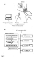
- Fig. 1(A) is an example of configuration of the image processing unit 10 and Fig. 1(B) shows a configuration of the image processing method 16.
- the image processing apparatus 10 mainly includes projector 12 for light projection method, camera 14 for image capturing method and, for example, a personal computer for the image processing method 16.
- Projector 12 has a function to project a light with predetermined pattern to a target object 18 and as for an actual device, for example, video projector can be considered. It is also possible to configure or align line-laser projectors as for an actual devise. Otherwise, using prism or beamsplitter to split laser light source into multiple directions is also possible.
- Projector 12 projects two types of patterns, such as vertical and horizontal directional pattern to a target object.
- vertical pattern (the first pattern) and horizontal pattern (the second pattern) are perpendicular to each other and those are distinguished by for example color information. In this invention, only two patterns' discrimination is required, selection of two colors from RGB (red, green and blue) is one solution.
- wave length for vertical and horizontal pattern is enough for the invention, invisible light source (e.g., infrared) can be used.
- specific wave length for light source high precision discrimination can be achieved by capturing with a narrow band path filter.
- width of pattern or angle of pattern can be used to distinguish two kinds of pattern. It is only required that vertical and horizontal lines are extracted from image, therefore, projecting a grid based pattern and extracting lines from an image or projecting a band where width is wider than a line and extracting boundary of the band are also sufficient. It is advantageous to use boundary of a band because it can extract two times pattern of a number of bands. Further, projecting checker board pattern and extracting a boundary of the pattern is also sufficient.
- Camera 14 has a function to capture a reflected light from an object by projecting a light from projector 12 and as for an actual device, for example, CCD image sensor, solid imaging device, etc. can be used.
- 2D image is captured by camera 14 and by performing image process 16 on data based on 2D image, 3D shape of object 18 is reconstructed.
- relative position of camera 14 and projector 12 can be either calibrated before scan, calibrated online, or self-calibrated, and can be assumed to be known.
- An image processing apparatus 16 mainly includes an image processing unit 30, a control unit 20, an input unit 22, a storage unit 24, a display unit 26, and a manipulation unit 28.
- the schematic function of the image processing apparatus 16 is to processing 2D image so as to reconstruct and output 3D shape.
- an implemented image processing apparatus 16 may be constructed with a computer such as a personal computer where an application (program) of executing a predetermined function is installed or a dedicated image-processing apparatus of executing a predetermined function.
- units constituting the image processing apparatus 16 are electrically connected to each other via a bus.
- the image processing unit 30 is a unit that mainly performs an image processing function.
- the image processing unit 30 includes a intersection obtaining unit 32, the first solution calculation unit 34, the second solution calculation unit 35, and 3D shape reconstruction unit 38.
- the intersection obtaining unit 32 (the first solution calculation unit) is a unit that obtain intersection of vertical and horizontal patterns which are detected from 2D image captured by camera 14.
- the first solution calculation unit 34 (the second calculation unit) is a unit that calculate the first solution including a degree of freedom by using a constraint that aforementioned patterns share intersection point, a constraint that plane including pattern pass through the predetermined common line and constraint obtained from the relative positional relationship between camera 14 and projector 12.
- the second solution calculation unit 36 (the third calculation unit) is a unit that calculate the second solution by eliminating a degree of freedom of the first solution calculated by the first solution calculation unit.
- 3D shape reconstruction unit 38 is a unit that reconstructs the 3D shape of captured object using the calculated second solution.
- the control unit 20 is a unit that controls operations of the entire units of the image processing apparatus 16 (the image processing unit 30, the input unit 22, the storage unit 24, and the display unit 26).
- the input unit 22 is a unit where information is externally input to the image processing apparatus 16. In the embodiment, a movie or an image consist of 2-D image is input from the input unit 16.
- the storage unit 24 is a fixed storage disk such as a HDD (hard disk drive), a detachable storage disk such as a CD (compact Disc) or DVD (digital versatile disk), a fixed or detachable semiconductor device, or the like.
- a plurality of the 2-D image before the process and 3-D shape reconstructed from the 2-D image are stored in the storage unit 18.
- a program for executing the image processing method described later is stored in the storage unit 24.
- the program allows functions of the aforementioned units to be executed by user's manipulation of the manipulation unit 28. More specifically, the units of the program are operated so that new 3-D shape reconstructed from the 2-D image.
- the display unit 26 is, for example, a liquid crystal display, a CRT (cathode ray tube), a video projector, or the like. An image is displayed on the display unit 20 based on the input 23-D image data or the reconstructed 3-D shape data.
- the manipulation unit 28 is, for example, a keyboard or a mouse. By the user's manipulation of the manipulation unit 28, the image processing apparatus 16 integrates a plurality of the 3-D shape data.
- planes that are configured by a pattern projected from projector is defined.
- a line pattern that is projected from projector 12 defines a plane in a 3D space.
- a straight pattern projected by the projector sweeps a plane in 3D space.
- Planes defined by a vertical pattern and a horizontal pattern are respectively referred to as a vertical pattern plane (VPP) and a horizontal pattern plane (HPP).
- VPP vertical pattern plane
- HPP horizontal pattern plane
- the projector is assumed to have been calibrated. That is, all parameters for the VPPs and HPPs in 3D space are known (Hereafter, all the parameters and 3D positions for planes, lines and points are represented in the camera coordinate system.).
- a VPP and a HPP with known parameters are referred to as a calibrated VPP (CVPP) and a calibrated HPP (CHPP).
- CVPPs are assumed to contain the same line (such a set of planes is also known as a pencil of planes). The same assumption holds for all CHPPs.
- These lines are denoted as L v and L h and the optical center of the projector O p is the intersection of these lines.
- the point O p and the direction vectors for L v and L h are given by calibrating projector 12 and camera 14. Intersections of the vertical and horizontal patterns projected onto the surface of the target scene are extracted from images captured by the camera 14. Here, these points are referred to as captured intersections. Connectivity between the captured intersections is extracted by image processing.
- the pattern connecting these intersections can be determined to be a vertical or horizontal pattern, so captured intersections are related in one of two types of relationships, being "on the same VPP" or "on the same HPP".
- the correspondence from each VPP containing the captured intersections to a particular CVPP is assumed to be unknown.
- This type of VPPs with unknown correspondences is referred to as unknown VPPs (UVPPs) ( Fig. 4 ).
- the term unknown HPP (UHPP) is similarly defined.
- the goal of the problem is deciding correspondences from all the UVPPs and UHPPs to CVPP or CHPP (the decision is called, in other words, identifying UVPPs and UHPPs).
- UVPPs have one-to-one correspondences with detected vertical patterns and the CVPPs are known 3D planes
- the 3D positions of points on a detected vertical pattern can be obtained by light sectioning method using correspondences between UVPPs and CVPPs. If a projected line of a single CVPP becomes discontinuous on the image because of occlusions or other reasons, it can be observed as multiple vertical patterns. In this case, multiple UVPPs correspond to a single CVPP. The same things happen for UHPPs and CHPPs.
- an image processing method includes: a step S 10 to obtain data which is required for reconstruction of 3D shape of object, step S11 to calculate a solution by using coplanarity constraint existing in UVPP or UHPP, step S12 to eliminate a degree of freedom of the solution by matching between set of UVPP or UHPP and set of CVPP or CHPP, and step S13 to reconstruct 3D shape from the calculated solution.
- a degree of freedom of indeterminacy of the solution calculated at step S 11 is one, therefore, all the UVPP and UHPP can be determined by deciding one parameter in step S12.
- Such a process can be done by, for example, one dimensional search to minimize the sum of matching error between two planes.
- a data that is necessary for 3D reconstruction of object 18 in Fig.1 is acquired using image processing unit 10. More specifically, light of patterns that includes multiple patterns that are crossed at right angles is projected to object 18.
- Fig.7(A) light of patterns that are composed of vertical patterns and horizontal patterns that are crossed at right angles is projected from projector 12. Then, the reflected light from the object is captured by camera 14.
- Information from 2D images captured by camera 14 is an input to image processing method 16. By performing the image processing to an input 2D image of image processing method 16, 2D positions of intersection points between patterns are extracted by means of image processing.
- Fig. 7(B) examples of detected patterns or detected intersection points are shown.
- a method for obtaining constraint equations about UVPPs and UHPPs from intersection points that are captured by the camera, and for obtaining solutions of the planes (first solution) except for one degree of freedom is defined.
- CVPPs obtained by calibration be represented as V 1 , V2, ⁇ ⁇ ⁇ , V M , CHPPs be represented as H 1 , H 2 , ⁇ ⁇ ⁇ , H N .
- UVPPs and UHPPs obtained from the captured image be represented as v 1 , v 2 , ⁇ ,v m and h 1 , h 2 , ⁇ , h n , respectively.
- v k and h 1 [s k,1 , t k,1 ] T .
- the planes v k and h 1 can be represented by
- UVPPs there are assumed conditions that all the UVPPs include line L v and all the UHPPs include line L h . Also, L v and L h intersects at point O p . From these conditions, there are constraints between arbitrary variables s and c of equation (4), and the freedoms of the solution is reduced. In the following, how to obtain general solution considering these conditions is described.
- the plane that includes both L v and L h is referred to as the projector focal plane (PFP) and its plane parameter is described as p.
- PFP projector focal plane
- p plane parameter
- UVPPs contain the line L v
- UHPPs contain the line L h
- all the planes contain the point O p .
- both v k -p and v' k -p are perpendicular to both l v and o p . Since l v and o p are not parallel in general, the vector that is perpendicular to these two vectors can be determined uniquely except for the scaling.
- Equation (11) means that, from images of intersection points between vertical patterns and horizontal patterns, the positions of their corresponding planes (i.e. UVPPs and UHPPs) can be solved except for one degree of freedom. Obtaining this representation of solution needs requirements such as follows. We define that, if an intersection point between two curves of a UVPP and a UHPP is detected, the two planes are connected. We also define that, if planes a and b are connected and planes b and c are connected in the above meaning, then planes a and c are connected. For a set of UVPPs and UHPPs, and an arbitrary element of the set is connected to all the other elements, then the set is called a connected set. Figure 5 shows an example of a connected set. Under these definitions, if a set of UVPPs and UHPPs are a connected set, then the solutions of the positions of all the planes in the set can be solved by equation(11).
- the indeterminacy is only one degree of freedom for the first plane.
- the equation (11) expresses this form of solution. However, if a set of UVPPs and UHPPs is not a connected set, the degree of freedoms of the whole solution is equal to or more than 2, since there are no constraints between planes that are not included in a single connected set. Thus, a necessary and sufficient condition for the set of all the planes to be expressed by equation (11) is that the set is a connected set.
- the set of UVPPs and UHPPs are assumed to be a connected set. if multiple connected sets are obtained from the target scene, it is sufficient to apply the invention for each of the connected sets. Thus, this does not reduce generality of the invention. Dividing UVPPs and UHPPs into connected sets can be easily implemented using labeling process applied to the images. Another efficient method to achieve the same result is examining the connection relationships of a graph that are composed of detected vertical and horizontal patterns and captured intersection points.
- the solution with remaining one degree of freedom obtained in step 11 can be sufficiently useful.
- the remaining parameter of the solution with one degree of freedom may be decided arbitrary because the distortion of the shape becomes relatively small.
- the output of step S10 may be a sufficiently useful result.
- the rendered image seems natural enough, and can be used for movies, games, or digital archives as it is.
- output of step S11 can be a practical result.
- matching is processed between the solution obtained in the previous step and the set of CVPPs and CHPPs, and the result is correspondences between UVPPs and CVPPs, or correspondences between UHPPs and CHPPs.
- a parameter of the solution of the previous step is decided such that the solution and the set of CVPPs and CHPPs coincide.
- the solution of the previous step of UVPPs and UHPPs is obtained from only the captured intersection points, and information of CVPPs and CHPPs is not used. Since the degree of freedom of the solution is one, matching can be processed efficiently using 1D search, and a solution with no remaining degrees of freedom (second solution) can be obtained.
- the corresponding plane v 10 is changed to V 2 , V 3 ⁇ and each set of plane positions of UVPPs and UHPPs obtained form the correspondences is evaluated if it matches the set of UVPPs and CHPPs.
- Form (11) has an indeterminacy of parameter s.
- the parameter can be calculated as follows by assuming a specific correspondence between a UVPP and CVPP. By assuming the correspondence from the k'-th UVPP to the i'-th
- the next step is comparing the calculated UVPPs (or UHPPs) with the CVPPs (or CHPPs). For each UVPP, the difference between the UVPP and the nearest CHPP is calculated as an error. Then, we can define a match estimation for an assumed correspondence v k' ⁇ V i' as the sum of squared errors for all the UVPPs (the smaller the squared errors are, the better matched the plane sets are). By searching for the minimum of the error function, we can find the optimum correspondence and solve the ambiguity.
- comparison is done based on the squared angles between the planes. More specifically, the error function is defined as
- d(g,h) means a difference of angle between direction vectors of line g and line h.
- d(g,h) means a difference of angle between direction vectors of line g and line h.
- the same process is applied for all the h, and the error function is defined as the sum of squares of the angle differences d(g,h).
- the parameter such that the error function is the minimum can be obtained, as similarly to step S12.
- the shape is reconstructed by light sectioning method. More specifically, as shown in Fig. 6 , the 3D points on object 18 are calculated as intersection points between the plane parameter and the line of sight that includes both detected edges and the optical center of camera 14.
- the 3D shape of the object captured by the camera can be reconstructed.
- a pattern is not required to be encoded like deBruijn sequence, and a single color is sufficient. Since a single color is sufficient, the technique is less affected by texture color and a stable detection is possible by simple image processing. Further, it is not spatially encoded, one pixel width of pattern is sufficient and very dense shape reconstruction can be achieved.
- each of the single-colored patterns into classes of vertical patterns or horizontal patterns.
- it is robust against textures.
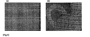
- shapes of the target For example, in case that the target shape is a cylinder, where normal directions at the front region and the side region are different largely, with a pattern of uniform frequency may result in detection failure, because the appearances of the pattern are compressed at the side regions.
- adding patterns with different special frequency can solve this problem.
- FIG. 8(A) An actual example of such pattern is shown in Figure 8(A) .
- the detection result of vertical and horizontal patterns using this pattern is shown in Fig.8(B) and Fig.8(C) .
- coarse grids and dense grids are detected respectively.
- this type of pattern configuration and processing is called coarse-to-fine.
- different patterns can be parallel patterns with different density, or they can be completely independent patterns.
- results of Fig.8(B) and Fig.8(C) can be reconstructed independently and the resulting shapes can be merged.
- methods for merging a simple way that is easy to implement is taking union of the results. More precise method is improving coherency of lines shared by dense and coarse patterns based on statistical methods.
- the additional line patterns can be processed similarly as the abovementioned method: they can be represented as plane parameters written in the form of equation 1, linear equations are constructed for each of the intersection points with all the patterns, and, since a plane corresponding to each of the patterns includes a line that is decided from the direction of the pattern, simultaneous linear equations can be generated using methods that are similar to equations 9, 10.
- By solving the equations one can reconstruct shapes for patterns with a set of lines whose directions are more than three kinds of directions. Using this method, one can solve the case of non-parallel sets of dense and coarse vertical lines (not like the example of Fig.8(A) ) by simply solving one set of equations).
- the set of planes of the vertical patterns is a set of planes that share a single line.
- the condition that the planes share a single line is replaced by the condition that "the planes share a single line at infinity".
- the lines L v and L h in the second embodiment share a single point at infinity Op.
- a real system can be achieved by arranging line-laser light sources in parallel. Using this configuration, one can get the pattern light with the same intervals even if the object moves far away from the light source. Thus, the light source can be placed far away from the target, and can be useful for 3D measurement.
- the vertical and horizontal patterns are colored in red and blue, respectively, these lines are divided by using red and blue planes of the captured image.
- using simple thresholding is one method.
- the intensity of the line can be varied by distance from the light source to the surface, or by difference of normal directions of the surface points, it is difficult to achieve precise line detection for all the image by simple thresholding.
- using edge filters such as canny filters is a method to achieve stable result.
- edge filters may be affected by erroneously detected edges of textures or of boundaries of objects.
- One method to avoid this is dividing the whole image into small blocks, a threshold value is decided for each of the blocks, and detecting lines for each block by thresolding.
- vertical and horizontal projected patterns that are crossed by right angles can be detected, even in the camera coordinates, as vertical and horizontal patterns that are crossed by right angles.
- a same pattern is not scanned twice.
- the number of variables in the equations is 3(m+n) where m is the number of UVPPs and n is the number of UHPPs.
- planes are represented by a single parameter.
- the number of variables is reduced by 1/3, and the processing time for reconstructing 3D shapes is reduced.
- both v k and h 1 are planes that includes o p (this plane is PFP and expressed as p), and the two planes are perpendicular to 1 v and 1 h respectively.
- n the number of UVPPs
- Kto the number of intersection points
- ⁇ (k) j ⁇ , the following equation holds:
- ⁇ j ⁇ k ⁇ ⁇ - 1 j ⁇ k ⁇ k ⁇ ⁇ k ⁇ ⁇ - 1 j ⁇ k 2
- ⁇ j can be expressed as a linear combination of ⁇ k . This can be expressed as
- Equation 35 ⁇ ⁇ ⁇ ⁇ 1 ⁇ ⁇ n ⁇
- the column indexes k 1 , k 2 , ⁇ ⁇ ⁇ are elements of ⁇ -1 (j), which is the set of indexes of all the UHPPs that have intersection points with the j-th UVPP. Then, from
- PRq 0 by considering errors by minimizing the sum of squared errors. This can be solved by calculating the eigenvector of matrix R T P T PR T that is associated to the minimum Eigen value.
- R T P T PR T is a n ⁇ n matrix. If we use dense vertical patterns and coarse horizontal patterns, n (the number of UHPPs) is much smaller than m (the number of UVPPs). In this case, the above problem can be solved much efficiently than solving the problem of minimizing ⁇ Pq ⁇ 2 with respect to q.
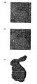
- the proposed method is tested using data synthesized by a simulation.
- the simulation is done using multiple grid patterns.
- the first pattern is uniformly spaced grid pattern.
- the second pattern is purpose-fully randomized to disturb the uniformity of the grid pattern.
- the simulated images for each of the experimental grid patterns are shown in Fig. 9(A) and Fig.9(B) .
- the intervals of the vertical patterns were about 5 pixels.
- the intersections of the grid patterns were extracted from the images and the correspondences from the UHPPs and UVPPs to the CVPPs and CHPPs were determined using the proposed method.
- the correct correspondences for all the UHPP and UVPP were selected and the reconstructed shapes exactly matched the ground truth.
- the shape obtained using the second pattern with the ground truth is shown in Fig. 9(C) .
- Figure 12 shows the captured scenes and results of reconstruction.
- a ceramic bottle, a paper mask and a ceramic jug with an intricate shape were captured.
- detailed shapes were successfully recovered with the current method.
- Fig.12(A) shows a target object
- Fig.12(B)-Fig.12(E) show the reconstruction result
- Fig.12(F) shows a target object
- Fig.12(G)-Fig.12(I) show the reconstruction result.
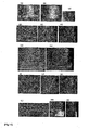
- a scene of a box (size: 0.4 m ⁇ 0.3 m ⁇ 0.3 m) and a cylinder (height: 0.2 m, diameter: 0.2 m) was measured by the abovementioned coarse-to-fine method.
- the same scene was measured by a coded structured light method as a ground truth.
- Fig. 13(A) shows the captured object
- Fig.13(B) and Fig. 13(C) show input image
- Fig. 13(D) shows detected horizontal patterns
- Fig.13(E) shows detected dense vertical patterns
- Fig. 13(A) shows the captured object
- Fig.13(B) and Fig. 13(C) show input image
- Fig. 13(D) shows detected horizontal patterns
- Fig.13(E) shows detected dense vertical patterns
- Fig. 13(A) shows the captured object
- Fig.13(B) and Fig. 13(C) show input image
- Fig. 13(D) shows detected horizontal patterns
- FIG. 13(F) shows detected coarse vertical patterns
- Fig.13(G) shows the intersection points of dense patterns
- Fig.13(H) shows intersection points of coarse patterns
- Fig.13(I) shows reconstructed shape of dense patterns
- Fig. 13(J) shows reconstructed shape of coarse patterns
- Fig.13(K) shows the unified result
- Fig.13(L)-Fig.13(N) show the reconstructed shape and the ground truth shape.
- Fig. 14 a human face was measured.
- the appearance of the experiment is shown in Fig. 14(A) and Fig.14(B) .
- Three examples of the reconstructed face expression is shown in Figs.14(C)-(E) .
- Results indicate that the proposed method successfully restored the complex human facial expressions with dense and accurate 3D point clouds.
Landscapes
- Engineering & Computer Science (AREA)
- Physics & Mathematics (AREA)
- General Physics & Mathematics (AREA)
- Computer Vision & Pattern Recognition (AREA)
- Theoretical Computer Science (AREA)
- Optics & Photonics (AREA)
- Length Measuring Devices By Optical Means (AREA)
- Image Processing (AREA)
- Image Analysis (AREA)
Applications Claiming Priority (2)
| Application Number | Priority Date | Filing Date | Title |
|---|---|---|---|
| JP2008155605A JP5317169B2 (ja) | 2008-06-13 | 2008-06-13 | 画像処理装置、画像処理方法およびプログラム |
| PCT/JP2009/002511 WO2009150799A1 (ja) | 2008-06-13 | 2009-06-04 | 画像処理装置、画像処理方法およびプログラム |
Publications (3)
| Publication Number | Publication Date |
|---|---|
| EP2295932A1 EP2295932A1 (en) | 2011-03-16 |
| EP2295932A4 EP2295932A4 (en) | 2012-09-05 |
| EP2295932B1 true EP2295932B1 (en) | 2014-10-08 |
Family
ID=41416512
Family Applications (1)
| Application Number | Title | Priority Date | Filing Date |
|---|---|---|---|
| EP09762230.2A Not-in-force EP2295932B1 (en) | 2008-06-13 | 2009-06-04 | Image processing device, image processing method, and program |
Country Status (4)
| Country | Link |
|---|---|
| US (1) | US8837812B2 (ja) |
| EP (1) | EP2295932B1 (ja) |
| JP (1) | JP5317169B2 (ja) |
| WO (1) | WO2009150799A1 (ja) |
Cited By (2)
| Publication number | Priority date | Publication date | Assignee | Title |
|---|---|---|---|---|
| DE102018115673A1 (de) * | 2018-06-28 | 2020-02-13 | Carl Zeiss Ag | Verfahren und Vorrichtungen zur Musterprojektion |
| US11425342B2 (en) | 2018-09-27 | 2022-08-23 | Rovi Guides, Inc. | Systems and methods for media projection surface selection |
Families Citing this family (48)
| Publication number | Priority date | Publication date | Assignee | Title |
|---|---|---|---|---|
| US9035876B2 (en) | 2008-01-14 | 2015-05-19 | Apple Inc. | Three-dimensional user interface session control |
| US8933876B2 (en) | 2010-12-13 | 2015-01-13 | Apple Inc. | Three dimensional user interface session control |
| US9170097B2 (en) | 2008-04-01 | 2015-10-27 | Perceptron, Inc. | Hybrid system |
| WO2010103482A2 (en) * | 2009-03-13 | 2010-09-16 | Primesense Ltd. | Enhanced 3d interfacing for remote devices |
| US9091536B2 (en) * | 2009-06-01 | 2015-07-28 | Dentsply International Inc. | Method and device for three-dimensional surface detection with a dynamic reference frame |
| JP5578844B2 (ja) | 2009-12-21 | 2014-08-27 | キヤノン株式会社 | 情報処理装置、情報処理方法及びプログラム |
| CN102781335B (zh) * | 2010-02-02 | 2016-05-18 | 普兰梅卡有限公司 | 牙科计算机断层摄影设备 |
| JP5631025B2 (ja) * | 2010-03-10 | 2014-11-26 | キヤノン株式会社 | 情報処理装置、その処理方法及びプログラム |
| JP2011242183A (ja) * | 2010-05-17 | 2011-12-01 | Hiroshima City Univ | 画像処理装置、画像処理方法およびプログラム |
| JP5615055B2 (ja) * | 2010-06-18 | 2014-10-29 | キヤノン株式会社 | 情報処理装置及びその処理方法 |
| US9201501B2 (en) | 2010-07-20 | 2015-12-01 | Apple Inc. | Adaptive projector |
| WO2012011044A1 (en) | 2010-07-20 | 2012-01-26 | Primesense Ltd. | Interactive reality augmentation for natural interaction |
| US8704890B2 (en) * | 2010-08-19 | 2014-04-22 | Olympus Corporation | Inspection apparatus and measuring method |
| US8959013B2 (en) * | 2010-09-27 | 2015-02-17 | Apple Inc. | Virtual keyboard for a non-tactile three dimensional user interface |
| US8872762B2 (en) | 2010-12-08 | 2014-10-28 | Primesense Ltd. | Three dimensional user interface cursor control |
| CN103347437B (zh) | 2011-02-09 | 2016-06-08 | 苹果公司 | 3d映射环境中的凝视检测 |
| AT511223B1 (de) | 2011-03-18 | 2013-01-15 | A Tron3D Gmbh | Vorrichtung zum aufnehmen von bildern von dreidimensionalen objekten |
| US9377865B2 (en) | 2011-07-05 | 2016-06-28 | Apple Inc. | Zoom-based gesture user interface |
| US8881051B2 (en) | 2011-07-05 | 2014-11-04 | Primesense Ltd | Zoom-based gesture user interface |
| US9459758B2 (en) | 2011-07-05 | 2016-10-04 | Apple Inc. | Gesture-based interface with enhanced features |
| JP6097903B2 (ja) * | 2011-07-15 | 2017-03-22 | 有限会社テクノドリーム二十一 | 3次元形状の取得装置、処理方法およびプログラム |
| JP5761750B2 (ja) * | 2011-07-19 | 2015-08-12 | 国立研究開発法人産業技術総合研究所 | 画像処理方法および装置 |
| US9030498B2 (en) | 2011-08-15 | 2015-05-12 | Apple Inc. | Combining explicit select gestures and timeclick in a non-tactile three dimensional user interface |
| US9122311B2 (en) | 2011-08-24 | 2015-09-01 | Apple Inc. | Visual feedback for tactile and non-tactile user interfaces |
| US9218063B2 (en) | 2011-08-24 | 2015-12-22 | Apple Inc. | Sessionless pointing user interface |
| US9229534B2 (en) | 2012-02-28 | 2016-01-05 | Apple Inc. | Asymmetric mapping for tactile and non-tactile user interfaces |
| WO2013144807A1 (en) | 2012-03-26 | 2013-10-03 | Primesense Ltd. | Enhanced virtual touchpad and touchscreen |
| US9217636B2 (en) * | 2012-06-11 | 2015-12-22 | Canon Kabushiki Kaisha | Information processing apparatus, information processing method, and a computer-readable storage medium |
| US9633439B2 (en) | 2012-07-30 | 2017-04-25 | National Institute Of Advanced Industrial Science And Technology | Image processing system, and image processing method |
| EP2918967B1 (en) * | 2012-11-07 | 2018-05-16 | Artec Europe S.a.r.l. | Method for monitoring linear dimensions of three-dimensional objects |
| DE102012024223B4 (de) * | 2012-12-11 | 2022-06-23 | Carl Zeiss Optotechnik GmbH | Verfahren und Vorrichtung zum Bestimmen der 3D-Koordinaten eines Objekts |
| US20140307055A1 (en) | 2013-04-15 | 2014-10-16 | Microsoft Corporation | Intensity-modulated light pattern for active stereo |
| US20140313293A1 (en) * | 2013-04-23 | 2014-10-23 | Speech Innovation Consulting Group Co., Ltd. | Depth measuring schemes |
| US20150009290A1 (en) * | 2013-07-05 | 2015-01-08 | Peter MANKOWSKI | Compact light module for structured-light 3d scanning |
| US9424809B1 (en) * | 2013-07-15 | 2016-08-23 | Google Inc. | Patterned projection with multi-panel display |
| US20150302648A1 (en) * | 2014-02-18 | 2015-10-22 | Sulon Technologies Inc. | Systems and methods for mapping an environment using structured light |
| TWI503518B (zh) * | 2014-12-29 | 2015-10-11 | Pixart Imaging Inc | 測距方法與裝置 |
| CN105096269B (zh) * | 2015-07-21 | 2018-03-02 | 北京交通大学 | 基于畸变直线结构检测的图像径向畸变矫正的方法及系统 |
| EP3542127B1 (en) * | 2016-11-21 | 2021-12-22 | Carestream Dental Technology Topco Limited | 3-d intraoral surface characterization |
| JP6702171B2 (ja) * | 2016-12-22 | 2020-05-27 | カシオ計算機株式会社 | 投影制御装置、投影制御方法及びプログラム |
| US11076093B2 (en) | 2017-01-25 | 2021-07-27 | National Institute Of Advanced Industrial Science And Technology | Image processing method |
| US10612912B1 (en) | 2017-10-31 | 2020-04-07 | Facebook Technologies, Llc | Tileable structured light projection system |
| US20190180475A1 (en) * | 2017-12-08 | 2019-06-13 | Qualcomm Incorporated | Dynamic camera calibration |
| JP6880512B2 (ja) * | 2018-02-14 | 2021-06-02 | オムロン株式会社 | 3次元測定装置、3次元測定方法及び3次元測定プログラム |
| US10521926B1 (en) | 2018-03-21 | 2019-12-31 | Facebook Technologies, Llc | Tileable non-planar structured light patterns for wide field-of-view depth sensing |
| US10650584B2 (en) * | 2018-03-30 | 2020-05-12 | Konica Minolta Laboratory U.S.A., Inc. | Three-dimensional modeling scanner |
| US10839536B2 (en) * | 2018-10-02 | 2020-11-17 | Facebook Technologies, Llc | Depth sensing using grid light patterns |
| US20220230335A1 (en) * | 2021-01-20 | 2022-07-21 | Nicolae Paul Teodorescu | One-shot high-accuracy geometric modeling of three-dimensional scenes |
Family Cites Families (6)
| Publication number | Priority date | Publication date | Assignee | Title |
|---|---|---|---|---|
| JPH0615968B2 (ja) * | 1986-08-11 | 1994-03-02 | 伍良 松本 | 立体形状測定装置 |
| US5705444A (en) | 1996-05-06 | 1998-01-06 | Minnesota Mining & Manufacturing Company | Filter material of ceramic oxide fibers and vermiculite particles |
| EP1009969B1 (en) * | 1996-06-13 | 2003-11-05 | K.U. Leuven Research & Development | Method and system for acquiring a three-dimensional shape description |
| US5917937A (en) * | 1997-04-15 | 1999-06-29 | Microsoft Corporation | Method for performing stereo matching to recover depths, colors and opacities of surface elements |
| US7747067B2 (en) * | 2003-10-08 | 2010-06-29 | Purdue Research Foundation | System and method for three dimensional modeling |
| EP1777485A4 (en) * | 2004-08-03 | 2012-09-19 | Techno Dream 21 Co Ltd | METHOD AND DEVICE FOR MEASURING THREE-DIMENSIONAL FORMS |
-
2008
- 2008-06-13 JP JP2008155605A patent/JP5317169B2/ja not_active Expired - Fee Related
-
2009
- 2009-06-04 WO PCT/JP2009/002511 patent/WO2009150799A1/ja active Application Filing
- 2009-06-04 US US12/997,088 patent/US8837812B2/en not_active Expired - Fee Related
- 2009-06-04 EP EP09762230.2A patent/EP2295932B1/en not_active Not-in-force
Cited By (2)
| Publication number | Priority date | Publication date | Assignee | Title |
|---|---|---|---|---|
| DE102018115673A1 (de) * | 2018-06-28 | 2020-02-13 | Carl Zeiss Ag | Verfahren und Vorrichtungen zur Musterprojektion |
| US11425342B2 (en) | 2018-09-27 | 2022-08-23 | Rovi Guides, Inc. | Systems and methods for media projection surface selection |
Also Published As
| Publication number | Publication date |
|---|---|
| US20110081072A1 (en) | 2011-04-07 |
| JP2009300277A (ja) | 2009-12-24 |
| WO2009150799A1 (ja) | 2009-12-17 |
| EP2295932A1 (en) | 2011-03-16 |
| EP2295932A4 (en) | 2012-09-05 |
| JP5317169B2 (ja) | 2013-10-16 |
| US8837812B2 (en) | 2014-09-16 |
Similar Documents
| Publication | Publication Date | Title |
|---|---|---|
| EP2295932B1 (en) | Image processing device, image processing method, and program | |
| Rocchini et al. | A low cost 3D scanner based on structured light | |
| US7570805B2 (en) | Creating 3D images of objects by illuminating with infrared patterns | |
| Kawasaki et al. | Dynamic scene shape reconstruction using a single structured light pattern | |
| Scharstein et al. | High-accuracy stereo depth maps using structured light | |
| EP2881702B1 (en) | Image processing system, and image processing method | |
| US20120176478A1 (en) | Forming range maps using periodic illumination patterns | |
| US20120176380A1 (en) | Forming 3d models using periodic illumination patterns | |
| Fu et al. | Fast spatial–temporal stereo matching for 3D face reconstruction under speckle pattern projection | |
| Nehab et al. | Improved sub-pixel stereo correspondences through symmetric refinement | |
| Balzer et al. | Cavlectometry: Towards holistic reconstruction of large mirror objects | |
| Winkelbach et al. | Shape from 2D edge gradients | |
| Koschan et al. | Dense depth maps by active color illumination and image pyramids | |
| Dizeu et al. | Frequency shift triangulation: a robust fringe projection technique for 3D shape acquisition in the presence of strong interreflections | |
| Grochulla et al. | Combining photometric normals and multi-view stereo for 3d reconstruction | |
| Furukawa et al. | Shape from grid pattern based on coplanarity constraints for one-shot scanning | |
| Li et al. | Structured light based reconstruction under local spatial coherence assumption | |
| Bender et al. | A Hand-held Laser Scanner based on Multi-camera Stereo-matching | |
| Ouji et al. | A space-time depth super-resolution scheme for 3D face scanning | |
| Schmalz et al. | A graph-based approach for robust single-shot structured light | |
| Amor et al. | 3D face modeling | |
| Vianello | Robust 3D surface reconstruction from light fields | |
| El-etriby | 3D range data acquisition using structured lighting and accuracy phase-based stereo algorithm | |
| Denker | Acquisition and On-line Reconstruction of 3D Point Data from Hand-held Laser Scanners and Multi-camera Stereo-matching | |
| Furukawa et al. | 3D Scanning Method for Fast Motion using Single Grid Pattern with Coarse-to-fine |
Legal Events
| Date | Code | Title | Description |
|---|---|---|---|
| PUAI | Public reference made under article 153(3) epc to a published international application that has entered the european phase |
Free format text: ORIGINAL CODE: 0009012 |
|
| 17P | Request for examination filed |
Effective date: 20110111 |
|
| AK | Designated contracting states |
Kind code of ref document: A1 Designated state(s): AT BE BG CH CY CZ DE DK EE ES FI FR GB GR HR HU IE IS IT LI LT LU LV MC MK MT NL NO PL PT RO SE SI SK TR |
|
| AX | Request for extension of the european patent |
Extension state: AL BA RS |
|
| DAX | Request for extension of the european patent (deleted) | ||
| REG | Reference to a national code |
Ref country code: DE Ref legal event code: R079 Ref document number: 602009027092 Country of ref document: DE Free format text: PREVIOUS MAIN CLASS: G01B0011250000 Ipc: G06T0007000000 |
|
| A4 | Supplementary search report drawn up and despatched |
Effective date: 20120806 |
|
| RIC1 | Information provided on ipc code assigned before grant |
Ipc: G06T 7/00 20060101AFI20120731BHEP Ipc: G01B 11/25 20060101ALI20120731BHEP Ipc: G06T 17/00 20060101ALI20120731BHEP Ipc: G06T 1/00 20060101ALI20120731BHEP |
|
| 17Q | First examination report despatched |
Effective date: 20130510 |
|
| GRAP | Despatch of communication of intention to grant a patent |
Free format text: ORIGINAL CODE: EPIDOSNIGR1 |
|
| INTG | Intention to grant announced |
Effective date: 20131022 |
|
| INTG | Intention to grant announced |
Effective date: 20131028 |
|
| GRAP | Despatch of communication of intention to grant a patent |
Free format text: ORIGINAL CODE: EPIDOSNIGR1 |
|
| INTG | Intention to grant announced |
Effective date: 20140417 |
|
| GRAS | Grant fee paid |
Free format text: ORIGINAL CODE: EPIDOSNIGR3 |
|
| GRAA | (expected) grant |
Free format text: ORIGINAL CODE: 0009210 |
|
| AK | Designated contracting states |
Kind code of ref document: B1 Designated state(s): AT BE BG CH CY CZ DE DK EE ES FI FR GB GR HR HU IE IS IT LI LT LU LV MC MK MT NL NO PL PT RO SE SI SK TR |
|
| REG | Reference to a national code |
Ref country code: GB Ref legal event code: FG4D |
|
| REG | Reference to a national code |
Ref country code: AT Ref legal event code: REF Ref document number: 690987 Country of ref document: AT Kind code of ref document: T Effective date: 20141015 Ref country code: CH Ref legal event code: EP |
|
| REG | Reference to a national code |
Ref country code: IE Ref legal event code: FG4D |
|
| REG | Reference to a national code |
Ref country code: DE Ref legal event code: R096 Ref document number: 602009027092 Country of ref document: DE Effective date: 20141120 |
|
| REG | Reference to a national code |
Ref country code: NL Ref legal event code: VDEP Effective date: 20141008 |
|
| REG | Reference to a national code |
Ref country code: AT Ref legal event code: MK05 Ref document number: 690987 Country of ref document: AT Kind code of ref document: T Effective date: 20141008 |
|
| REG | Reference to a national code |
Ref country code: LT Ref legal event code: MG4D |
|
| PG25 | Lapsed in a contracting state [announced via postgrant information from national office to epo] |
Ref country code: NL Free format text: LAPSE BECAUSE OF FAILURE TO SUBMIT A TRANSLATION OF THE DESCRIPTION OR TO PAY THE FEE WITHIN THE PRESCRIBED TIME-LIMIT Effective date: 20141008 |
|
| PG25 | Lapsed in a contracting state [announced via postgrant information from national office to epo] |
Ref country code: IS Free format text: LAPSE BECAUSE OF FAILURE TO SUBMIT A TRANSLATION OF THE DESCRIPTION OR TO PAY THE FEE WITHIN THE PRESCRIBED TIME-LIMIT Effective date: 20150208 Ref country code: FI Free format text: LAPSE BECAUSE OF FAILURE TO SUBMIT A TRANSLATION OF THE DESCRIPTION OR TO PAY THE FEE WITHIN THE PRESCRIBED TIME-LIMIT Effective date: 20141008 Ref country code: LT Free format text: LAPSE BECAUSE OF FAILURE TO SUBMIT A TRANSLATION OF THE DESCRIPTION OR TO PAY THE FEE WITHIN THE PRESCRIBED TIME-LIMIT Effective date: 20141008 Ref country code: ES Free format text: LAPSE BECAUSE OF FAILURE TO SUBMIT A TRANSLATION OF THE DESCRIPTION OR TO PAY THE FEE WITHIN THE PRESCRIBED TIME-LIMIT Effective date: 20141008 Ref country code: NO Free format text: LAPSE BECAUSE OF FAILURE TO SUBMIT A TRANSLATION OF THE DESCRIPTION OR TO PAY THE FEE WITHIN THE PRESCRIBED TIME-LIMIT Effective date: 20150108 Ref country code: PT Free format text: LAPSE BECAUSE OF FAILURE TO SUBMIT A TRANSLATION OF THE DESCRIPTION OR TO PAY THE FEE WITHIN THE PRESCRIBED TIME-LIMIT Effective date: 20150209 |
|
| PG25 | Lapsed in a contracting state [announced via postgrant information from national office to epo] |
Ref country code: CY Free format text: LAPSE BECAUSE OF FAILURE TO SUBMIT A TRANSLATION OF THE DESCRIPTION OR TO PAY THE FEE WITHIN THE PRESCRIBED TIME-LIMIT Effective date: 20141008 Ref country code: GR Free format text: LAPSE BECAUSE OF FAILURE TO SUBMIT A TRANSLATION OF THE DESCRIPTION OR TO PAY THE FEE WITHIN THE PRESCRIBED TIME-LIMIT Effective date: 20150109 Ref country code: HR Free format text: LAPSE BECAUSE OF FAILURE TO SUBMIT A TRANSLATION OF THE DESCRIPTION OR TO PAY THE FEE WITHIN THE PRESCRIBED TIME-LIMIT Effective date: 20141008 Ref country code: PL Free format text: LAPSE BECAUSE OF FAILURE TO SUBMIT A TRANSLATION OF THE DESCRIPTION OR TO PAY THE FEE WITHIN THE PRESCRIBED TIME-LIMIT Effective date: 20141008 Ref country code: AT Free format text: LAPSE BECAUSE OF FAILURE TO SUBMIT A TRANSLATION OF THE DESCRIPTION OR TO PAY THE FEE WITHIN THE PRESCRIBED TIME-LIMIT Effective date: 20141008 Ref country code: SE Free format text: LAPSE BECAUSE OF FAILURE TO SUBMIT A TRANSLATION OF THE DESCRIPTION OR TO PAY THE FEE WITHIN THE PRESCRIBED TIME-LIMIT Effective date: 20141008 Ref country code: LV Free format text: LAPSE BECAUSE OF FAILURE TO SUBMIT A TRANSLATION OF THE DESCRIPTION OR TO PAY THE FEE WITHIN THE PRESCRIBED TIME-LIMIT Effective date: 20141008 |
|
| REG | Reference to a national code |
Ref country code: FR Ref legal event code: PLFP Year of fee payment: 7 |
|
| REG | Reference to a national code |
Ref country code: DE Ref legal event code: R097 Ref document number: 602009027092 Country of ref document: DE |
|
| PG25 | Lapsed in a contracting state [announced via postgrant information from national office to epo] |
Ref country code: EE Free format text: LAPSE BECAUSE OF FAILURE TO SUBMIT A TRANSLATION OF THE DESCRIPTION OR TO PAY THE FEE WITHIN THE PRESCRIBED TIME-LIMIT Effective date: 20141008 Ref country code: RO Free format text: LAPSE BECAUSE OF FAILURE TO SUBMIT A TRANSLATION OF THE DESCRIPTION OR TO PAY THE FEE WITHIN THE PRESCRIBED TIME-LIMIT Effective date: 20141008 Ref country code: CZ Free format text: LAPSE BECAUSE OF FAILURE TO SUBMIT A TRANSLATION OF THE DESCRIPTION OR TO PAY THE FEE WITHIN THE PRESCRIBED TIME-LIMIT Effective date: 20141008 Ref country code: DK Free format text: LAPSE BECAUSE OF FAILURE TO SUBMIT A TRANSLATION OF THE DESCRIPTION OR TO PAY THE FEE WITHIN THE PRESCRIBED TIME-LIMIT Effective date: 20141008 Ref country code: SK Free format text: LAPSE BECAUSE OF FAILURE TO SUBMIT A TRANSLATION OF THE DESCRIPTION OR TO PAY THE FEE WITHIN THE PRESCRIBED TIME-LIMIT Effective date: 20141008 |
|
| PLBE | No opposition filed within time limit |
Free format text: ORIGINAL CODE: 0009261 |
|
| STAA | Information on the status of an ep patent application or granted ep patent |
Free format text: STATUS: NO OPPOSITION FILED WITHIN TIME LIMIT |
|
| PG25 | Lapsed in a contracting state [announced via postgrant information from national office to epo] |
Ref country code: IT Free format text: LAPSE BECAUSE OF FAILURE TO SUBMIT A TRANSLATION OF THE DESCRIPTION OR TO PAY THE FEE WITHIN THE PRESCRIBED TIME-LIMIT Effective date: 20141008 |
|
| 26N | No opposition filed |
Effective date: 20150709 |
|
| PG25 | Lapsed in a contracting state [announced via postgrant information from national office to epo] |
Ref country code: MC Free format text: LAPSE BECAUSE OF FAILURE TO SUBMIT A TRANSLATION OF THE DESCRIPTION OR TO PAY THE FEE WITHIN THE PRESCRIBED TIME-LIMIT Effective date: 20141008 |
|
| REG | Reference to a national code |
Ref country code: CH Ref legal event code: PL |
|
| PG25 | Lapsed in a contracting state [announced via postgrant information from national office to epo] |
Ref country code: LU Free format text: LAPSE BECAUSE OF FAILURE TO SUBMIT A TRANSLATION OF THE DESCRIPTION OR TO PAY THE FEE WITHIN THE PRESCRIBED TIME-LIMIT Effective date: 20150604 Ref country code: SI Free format text: LAPSE BECAUSE OF FAILURE TO SUBMIT A TRANSLATION OF THE DESCRIPTION OR TO PAY THE FEE WITHIN THE PRESCRIBED TIME-LIMIT Effective date: 20141008 |
|
| REG | Reference to a national code |
Ref country code: IE Ref legal event code: MM4A |
|
| PG25 | Lapsed in a contracting state [announced via postgrant information from national office to epo] |
Ref country code: LI Free format text: LAPSE BECAUSE OF NON-PAYMENT OF DUE FEES Effective date: 20150630 Ref country code: CH Free format text: LAPSE BECAUSE OF NON-PAYMENT OF DUE FEES Effective date: 20150630 Ref country code: IE Free format text: LAPSE BECAUSE OF NON-PAYMENT OF DUE FEES Effective date: 20150604 |
|
| REG | Reference to a national code |
Ref country code: FR Ref legal event code: PLFP Year of fee payment: 8 |
|
| PG25 | Lapsed in a contracting state [announced via postgrant information from national office to epo] |
Ref country code: MT Free format text: LAPSE BECAUSE OF FAILURE TO SUBMIT A TRANSLATION OF THE DESCRIPTION OR TO PAY THE FEE WITHIN THE PRESCRIBED TIME-LIMIT Effective date: 20141008 |
|
| PG25 | Lapsed in a contracting state [announced via postgrant information from national office to epo] |
Ref country code: HU Free format text: LAPSE BECAUSE OF FAILURE TO SUBMIT A TRANSLATION OF THE DESCRIPTION OR TO PAY THE FEE WITHIN THE PRESCRIBED TIME-LIMIT; INVALID AB INITIO Effective date: 20090604 Ref country code: BG Free format text: LAPSE BECAUSE OF FAILURE TO SUBMIT A TRANSLATION OF THE DESCRIPTION OR TO PAY THE FEE WITHIN THE PRESCRIBED TIME-LIMIT Effective date: 20141008 |
|
| REG | Reference to a national code |
Ref country code: FR Ref legal event code: PLFP Year of fee payment: 9 |
|
| PGFP | Annual fee paid to national office [announced via postgrant information from national office to epo] |
Ref country code: FR Payment date: 20170621 Year of fee payment: 9 Ref country code: GB Payment date: 20170626 Year of fee payment: 9 |
|
| PG25 | Lapsed in a contracting state [announced via postgrant information from national office to epo] |
Ref country code: TR Free format text: LAPSE BECAUSE OF FAILURE TO SUBMIT A TRANSLATION OF THE DESCRIPTION OR TO PAY THE FEE WITHIN THE PRESCRIBED TIME-LIMIT Effective date: 20141008 |
|
| PG25 | Lapsed in a contracting state [announced via postgrant information from national office to epo] |
Ref country code: BE Free format text: LAPSE BECAUSE OF FAILURE TO SUBMIT A TRANSLATION OF THE DESCRIPTION OR TO PAY THE FEE WITHIN THE PRESCRIBED TIME-LIMIT Effective date: 20141008 |
|
| PGFP | Annual fee paid to national office [announced via postgrant information from national office to epo] |
Ref country code: DE Payment date: 20170628 Year of fee payment: 9 |
|
| PG25 | Lapsed in a contracting state [announced via postgrant information from national office to epo] |
Ref country code: MK Free format text: LAPSE BECAUSE OF FAILURE TO SUBMIT A TRANSLATION OF THE DESCRIPTION OR TO PAY THE FEE WITHIN THE PRESCRIBED TIME-LIMIT Effective date: 20141008 |
|
| REG | Reference to a national code |
Ref country code: DE Ref legal event code: R119 Ref document number: 602009027092 Country of ref document: DE |
|
| GBPC | Gb: european patent ceased through non-payment of renewal fee |
Effective date: 20180604 |
|
| PG25 | Lapsed in a contracting state [announced via postgrant information from national office to epo] |
Ref country code: DE Free format text: LAPSE BECAUSE OF NON-PAYMENT OF DUE FEES Effective date: 20190101 Ref country code: FR Free format text: LAPSE BECAUSE OF NON-PAYMENT OF DUE FEES Effective date: 20180630 Ref country code: GB Free format text: LAPSE BECAUSE OF NON-PAYMENT OF DUE FEES Effective date: 20180604 |