US11076093B2 - Image processing method - Google Patents
Image processing method Download PDFInfo
- Publication number
- US11076093B2 US11076093B2 US16/479,370 US201816479370A US11076093B2 US 11076093 B2 US11076093 B2 US 11076093B2 US 201816479370 A US201816479370 A US 201816479370A US 11076093 B2 US11076093 B2 US 11076093B2
- Authority
- US
- United States
- Prior art keywords
- image
- signal
- image processing
- spreading
- light
- Prior art date
- Legal status (The legal status is an assumption and is not a legal conclusion. Google has not performed a legal analysis and makes no representation as to the accuracy of the status listed.)
- Expired - Fee Related, expires
Links
Images


Classifications
-
- G—PHYSICS
- G06—COMPUTING OR CALCULATING; COUNTING
- G06T—IMAGE DATA PROCESSING OR GENERATION, IN GENERAL
- G06T7/00—Image analysis
- G06T7/50—Depth or shape recovery
- G06T7/521—Depth or shape recovery from laser ranging, e.g. using interferometry; from the projection of structured light
-
- H04N5/23229—
-
- G—PHYSICS
- G06—COMPUTING OR CALCULATING; COUNTING
- G06T—IMAGE DATA PROCESSING OR GENERATION, IN GENERAL
- G06T5/00—Image enhancement or restoration
- G06T5/73—Deblurring; Sharpening
-
- G—PHYSICS
- G01—MEASURING; TESTING
- G01B—MEASURING LENGTH, THICKNESS OR SIMILAR LINEAR DIMENSIONS; MEASURING ANGLES; MEASURING AREAS; MEASURING IRREGULARITIES OF SURFACES OR CONTOURS
- G01B11/00—Measuring arrangements characterised by the use of optical techniques
- G01B11/24—Measuring arrangements characterised by the use of optical techniques for measuring contours or curvatures
- G01B11/25—Measuring arrangements characterised by the use of optical techniques for measuring contours or curvatures by projecting a pattern, e.g. one or more lines, moiré fringes on the object
-
- G—PHYSICS
- G06—COMPUTING OR CALCULATING; COUNTING
- G06F—ELECTRIC DIGITAL DATA PROCESSING
- G06F3/00—Input arrangements for transferring data to be processed into a form capable of being handled by the computer; Output arrangements for transferring data from processing unit to output unit, e.g. interface arrangements
- G06F3/14—Digital output to display device ; Cooperation and interconnection of the display device with other functional units
-
- G06T5/002—
-
- G—PHYSICS
- G06—COMPUTING OR CALCULATING; COUNTING
- G06T—IMAGE DATA PROCESSING OR GENERATION, IN GENERAL
- G06T5/00—Image enhancement or restoration
- G06T5/20—Image enhancement or restoration using local operators
-
- G—PHYSICS
- G06—COMPUTING OR CALCULATING; COUNTING
- G06T—IMAGE DATA PROCESSING OR GENERATION, IN GENERAL
- G06T5/00—Image enhancement or restoration
- G06T5/70—Denoising; Smoothing
-
- H—ELECTRICITY
- H04—ELECTRIC COMMUNICATION TECHNIQUE
- H04B—TRANSMISSION
- H04B1/00—Details of transmission systems, not covered by a single one of groups H04B3/00 - H04B13/00; Details of transmission systems not characterised by the medium used for transmission
- H04B1/69—Spread spectrum techniques
- H04B1/707—Spread spectrum techniques using direct sequence modulation
- H04B1/7097—Interference-related aspects
-
- H—ELECTRICITY
- H04—ELECTRIC COMMUNICATION TECHNIQUE
- H04N—PICTORIAL COMMUNICATION, e.g. TELEVISION
- H04N23/00—Cameras or camera modules comprising electronic image sensors; Control thereof
- H04N23/56—Cameras or camera modules comprising electronic image sensors; Control thereof provided with illuminating means
-
- H—ELECTRICITY
- H04—ELECTRIC COMMUNICATION TECHNIQUE
- H04N—PICTORIAL COMMUNICATION, e.g. TELEVISION
- H04N23/00—Cameras or camera modules comprising electronic image sensors; Control thereof
- H04N23/80—Camera processing pipelines; Components thereof
-
- H—ELECTRICITY
- H04—ELECTRIC COMMUNICATION TECHNIQUE
- H04N—PICTORIAL COMMUNICATION, e.g. TELEVISION
- H04N23/00—Cameras or camera modules comprising electronic image sensors; Control thereof
- H04N23/95—Computational photography systems, e.g. light-field imaging systems
-
- H04N5/2256—
-
- H—ELECTRICITY
- H04—ELECTRIC COMMUNICATION TECHNIQUE
- H04N—PICTORIAL COMMUNICATION, e.g. TELEVISION
- H04N5/00—Details of television systems
- H04N5/44—Receiver circuitry for the reception of television signals according to analogue transmission standards
- H04N5/455—Demodulation-circuits
-
- G—PHYSICS
- G06—COMPUTING OR CALCULATING; COUNTING
- G06T—IMAGE DATA PROCESSING OR GENERATION, IN GENERAL
- G06T2207/00—Indexing scheme for image analysis or image enhancement
- G06T2207/10—Image acquisition modality
- G06T2207/10016—Video; Image sequence
-
- G—PHYSICS
- G06—COMPUTING OR CALCULATING; COUNTING
- G06T—IMAGE DATA PROCESSING OR GENERATION, IN GENERAL
- G06T2207/00—Indexing scheme for image analysis or image enhancement
- G06T2207/20—Special algorithmic details
- G06T2207/20048—Transform domain processing
- G06T2207/20056—Discrete and fast Fourier transform, [DFT, FFT]
-
- H—ELECTRICITY
- H04—ELECTRIC COMMUNICATION TECHNIQUE
- H04B—TRANSMISSION
- H04B2201/00—Indexing scheme relating to details of transmission systems not covered by a single group of H04B3/00 - H04B13/00
- H04B2201/69—Orthogonal indexing scheme relating to spread spectrum techniques in general
- H04B2201/707—Orthogonal indexing scheme relating to spread spectrum techniques in general relating to direct sequence modulation
- H04B2201/7097—Direct sequence modulation interference
- H04B2201/709709—Methods of preventing interference
Definitions
- the present invention relates to an image processing method, and specifically, to an image processing method to reconstruct an object shape or to display a concealed image on a screen or the like, by processing shot images including a specific pattern projected on a surface of the object under ambient light or displayed on the screen.
- PTL 1 discloses an image processing method to reconstruct a shape of a target object based on shot images including a grid pattern projected on a target object for observation.
- PTL 2 discloses an image processing method to reconstruct an object shape by using a phase of a synchronous pattern obtained by demodulating shot images including a projected pattern on a moving object.
- PTL 3 discloses an image processing method to reconstruct an object shape by using a band-pass filter based on shot images including a grid pattern projected on an object under ambient light.
- NPL 1 discloses an image processing method to reconstruct a shape of an object based on shot images by a camera under conditions that a plurality of light sources simultaneously irradiate lights to the object according to a pattern based on a Hadamard matrix. Furthermore, NPL 2 discloses a method to demodulate and restore (or display) information embedded in an image based on the spread spectrum modulation.
- Patent Literatures and Non Patent Literatures described above would achieve its individual objective relevant to the image processing method to reconstruct the object shape based on the shot images or to restore the embedded information in the image.
- these publications do not disclose an effective image processing method to reconstruct the object shape of a moving object under relatively-strong ambient light based on the shot images, or to demodulate a video image in which an invisible image is embedded and display the embedded image.
- An image processing method includes: (a) irradiating flashing light to a surface of an object based on a spreading signal obtained by spread spectrum modulation, (b) receiving reflected light from the surface of the object to output a signal including image information, (c) filtering for eliminating noise including a low-frequency component from the signal including the image information, (d) inverse-spreading and demodulating the signal after the filtering, and (e) outputting an image reflecting a state of the surface of the object based on a signal obtained by the demodulating.
- the image processing method of another embodiment of the present invention includes (a) preparing an image embedded in a video image to be displayed on a display screen, where the embedded image is displayed by lighting pixels of the display screen based on a spreading signal obtained by spread spectrum modulation, (b) shooting the video image including the embedded image displayed on the display screen, (c) filtering for eliminating noise including a low-frequency component from a signal of the shot video image, (d) inverse-spreading and demodulating the signal after the filtering, and (e) outputting the embedded image based on a signal obtained by the demodulating.
- An image processing system of one embodiment of the present invention includes (a) a light source for irradiating flashing light to a surface of an object based on a spreading signal obtained by spread spectrum modulation, (b) an imaging apparatus for receiving reflected light from the surface of the object and outputting a signal including image information, (c) a filter for eliminating noise including a low-frequency component from the signal including the image information, (d) an operation processing apparatus for inverse-spreading and demodulating the signal after processing by the filter, and (e) a display apparatus for displaying an image reflecting a state of the surface of the object based on a signal obtained by the demodulating.
- the shape of an object at rest or a moving object cab be measured under ambient light by using the illumination of spread spectrum modulation light to an object and a filtering processing of shot images of the object under irradiation.
- video may be embedded using the spread spectrum modulation in a video image to thereby display embedded image demodulated from shot images of the video image.
- FIG. 1 illustrates the configuration of an image processing system of one embodiment of the present invention
- FIG. 2 illustrates the flow of an image processing method of one embodiment of the present invention
- FIG. 3 illustrates the flow of the image processing method of another embodiment of the present invention
- FIG. 4 illustrates Illustrative Embodiment 1 of the present invention
- FIG. 5 illustrates Illustrative Embodiment 1 of the present invention
- FIG. 6 illustrates Illustrative Embodiment 2 of the present invention
- FIG. 7 illustrates Illustrative Embodiment 3 of the present invention
- FIG. 8 illustrates Illustrative Embodiment 3 of the present invention.
- FIG. 9 illustrates Illustrative Embodiment 4 of the present invention.
- FIG. 1 illustrates the configuration of an image processing system of one embodiment of the present invention.
- An image processing system 100 includes a light source 10 for irradiating light to an object 1 , an imaging apparatus 12 that may receive reflected light from the surface of the object, and an operation processing apparatus 14 that is connected to the light source 10 and the imaging apparatus 12 .
- the object 1 is an object that may be an object for which light may be reflected at least from the surface of the outer shape, in other words, an object whose video image may be shot by the imaging apparatus 12 , and it may be not only a stationary object but also a moving object.
- the moving object may be an (automatic) object moving by itself or a (passive) object moved by another means (mechanism).
- the light source 10 is configured to irradiate light to the surface of the object 1 based on a spreading signal obtained by the spread spectrum modulation.
- the spreading signal obtained by the spread spectrum modulation is supplied from the operation processing apparatus 14 .
- the light source 10 may be a light-irradiating source such as a light-irradiating diode (LED), laser diode (LD), or a video projector. More specifically, the light source 10 may be a laser pattern projector that may project a predetermined pattern (e.g., a dot pattern) onto the surface of the object 1 for example.
- the light source 10 may be a light source including the spectrum/spectra of a single wavelength or a plurality of wavelengths.
- the light source 10 may be at least one light source or may be the same or different types of light sources that may irradiate light from two or more different directions.
- the imaging apparatus 12 may be a camera such as an image sensor (area sensor) consisting of CMOS or CCD for example.
- the imaging apparatus 12 may be a monochrome or color (RGB) camera or a hyper spectrum camera.
- the imaging apparatus 12 must perform a shooting operation in synchronization with the light emission (flashing) of the light source 10 and thus may be a high-speed camera having a high shooting speed (frame/second).
- the imaging apparatus 12 outputs the signal including the image information (video data) to the operation processing apparatus 14 .
- the operation processing apparatus 14 may be a personal computer (PC) including a processor (CPU), a memory, and a display for example that numerically calculates the signal including the image information (video data) received from the imaging apparatus 12 to display the image.
- the operation processing apparatus 14 also may function as a filter providing the operation processing function thereof to eliminate noise including a low-frequency component from the signal including the image information (video data).
- the filter may be configured as an apparatus independent from or accompanying the operation processing apparatus 14 .
- the operation processing apparatus 14 further has a function for inverse-spreading and demodulating the signal after processing by the filter. Based on a signal obtained by the demodulating, an image reflecting the state of the surface of the object is displayed on the display provided in the operation processing apparatus 14 .
- FIG. 2 illustrates the flow of an image processing method of one embodiment of the present invention.
- the flow of FIG. 2 may be performed using the image processing system of FIG. 1 for example.
- the flow of FIG. 2 may be performed under indoor or outdoor ambient light (e.g., indoor lighting or sunlight).
- the ambient light may be ambient light having a relatively-strong light intensity (brightness) so long as the output from the respective photodetectors of the imaging apparatus 12 is not saturated.
- the system and the method of the present invention may have one characteristic that a specific image of the object surface may be obtained even under the relatively-strong ambient light (noise).
- Step S 1 of FIG. 2 flashing light is irradiated to the surface of the object based on the spreading signal obtained by the spread spectrum modulation.
- the light emission from flashing light is irradiated from the light source 10 to the surface of the object 1 based on the spreading signal obtained by the spread spectrum modulation.
- the spreading signal obtained by the spread spectrum modulation is generated by the operation processing apparatus 14 .
- the object 1 also may include not only an object at rest but also a moving object.
- the spread spectrum modulation may be performed using a direct sequence spread spectrum (DS).
- the spreading signal obtained by the spread spectrum modulation may be obtained by multiplying, with a spreading code composed of a pseudo random noise (PN)-sequence, the original signal (reference signal) to which the primary modulation was applied.
- the spreading code may include the longest series (MLS) code having a length L for example.
- the longest series (MLS) code having the length L may be generated using a linear feedback shift register (LFSR) included in the operation processing apparatus 14 for example.
- the spreading code also may be a Hadamard matrix including codes ( ⁇ 1 and 1) or an S matrix including a code (0, 1).
- the flashing light may be configured to include a predetermined grid pattern for example by using a laser pattern projector as the light source 10 .
- the flashing light also may include the spectrum having a single wavelength or a plurality of wavelengths.
- the flashing light may be irradiated to the object 1 in a plurality of different directions.
- Step S 2 the reflected light from the surface of the object is received to output the signal including the image information. Specifically, in the system of FIG.
- the reflected light from the surface of the object 1 is received by the imaging apparatus 12 , in other words, the system shoots the object 1 irradiated with flashing light by the imaging apparatus 12 , stores the resultant shot images in a built-in memory, and sends the shot images to the operation processing apparatus 14 .
- Step S 3 a filtering is performed to eliminate noise including a low-frequency component from the signal including the image information.
- the operation processing apparatus 14 uses a high-pass filter and selectively uses a spatial filter to process a shot video signal (video data) for eliminating a noise component.
- This noise component includes noise having a relatively-low frequency caused by ambient light during the shooting operation.
- the high-pass filtering may use the inverse discrete Fourier transform (IDFT) function for example to further use a window function (e.g., Hanning Window) (i.e., filtering by the high-pass filter may multiply the shot image signal (video data) with these functions) to thereby eliminate the low frequency noise and ripple noise.
- the spatial filtering may use a Gaussian filter for example.
- Step S 4 the signal (video data) after the filtering is inversely spread. Specifically, the signal after the filtering is multiplied with an inverse-spreading code to generate an inverse-spread signal.
- the inverse-spreading code may be the same code as the spreading code.
- Step S 5 the inversely spread signal is demodulated.
- the inverse-spreading in Step S 4 and the demodulation in Step S 5 may be simultaneously (or continuously) carried out in one step.
- Step S 6 based on a signal obtained by the demodulation, an image reflecting the state of the surface of the object is outputted.
- the image (video) may be displayed on a display provided in the operation processing apparatus 14 .
- the spread spectrum modulation (direct sequence spread spectrum) used in the image processing method in FIG. 2 has been conventionally used, as shown by the following equations (1)-(5) describing the signal flow, in the technical field such as radio communication.
- Features of the present invention significantly different from the prior art are (i) to use a light irradiated from a light source to an object, the light being flashing light to which spread spectrum modulation was applied, and (ii) to eliminate a noise component caused by ambient light or the like, by applying predetermined filtering before inverse-spreading the shot images of the object irradiated with the flashing light.
- the reference signal s k at the time t k is converted by function F to the primary modulation signal M 1 (t k ). It is established that kT ⁇ t k ⁇ (k+1)T (T: reference signal cycle, k: time step). Equation 1 M 1 ( t k ) F ( s k ) (1)
- the ambient light may be recognized, in a scene including no move, as a substantially-constant direct current (DC) component in a shot video signal.
- DC direct current
- the direct current (DC) component is, in a scene including a move, not constant and includes a relatively-low-frequency component changing depending on the move of the moving object slower than the shooting speed (frame rate).
- a high-pass filter must be used to eliminate the low-frequency component from the video signal to demodulate the resultant signal.
- the high-pass filter through which a frequency higher than the frequency ⁇ T is allowed to pass may be represented by equation (6) as a frequency region.
- Equation ⁇ ⁇ 6 H ⁇ ( ⁇ ) ⁇ 1 ⁇ > ⁇ T 0 otherwise ( 6 )
- IDFT inverse discrete Fourier transform
- the spectrum diffusion signal also has a low-frequency component that is not zero, the signal inverse-spread by equation (8) is influenced by the high-pass filter.
- the function F for demodulation must be deformed depending on the original function F.
- An additional noise filter may be obtained by a combination with a spatial filter.
- g(x, y) as a Gaussian filter may be applied to the reception signal.
- the terms x and y show the coordinate of the pixel.
- Equation ⁇ ⁇ 10 H [ h 0 ... 0 0 0 h 0 ... 0 ... 0 ... 0 h ] ( 10 )
- Equation 12 ( S T H T HS ) ⁇ 1 S T H T Hm. (12)
- coefficient matrices on the right side of equation (12) correspond to composite functions representing the inverse-spreading and the demodulation, and are used as filters convoluted with received signals for the demodulation.
- the individual signals are extracted using a spreading code circular-shifted from a code given by the longest series (MLS). It is assumed that S j is a column vector of the spreading code given by “j” circular shifts S.
- the coefficient matrix may be obtained by (13) as in the above-described case of one light source. Equation 13 ( Q T H T HQ ) ⁇ 1 Q T H T H, (13)
- Equation 14 [ S j1 S j2 . . . S jM ] (14)
- FIG. 3 illustrates the flow of the image processing method of another embodiment of the present invention.
- the flow of FIG. 3 may be carried out using the imaging apparatus 12 and the operation processing apparatus 14 in the system of FIG. 1 for example.
- Step S 10 embedded image in a video image to be displayed on a display screen is prepared.
- the spreading signal obtained by the spread spectrum modulation is generated to display embedded image by the operation processing apparatus 14 into the video image for example.
- the video is prepared so as to be displayed on the display included in the operation processing apparatus 14 (or to light the pixels of the display).
- the display includes a liquid crystal monitor or a video projector for example.
- the display of the embedded image to which the spread spectrum modulation is applied is set to a low optical output with a relatively-high frequency (the brightness of the respective pixels) so that the video may not be directly visually recognized during the reproduction of the video image.
- Step S 11 the system shoots the video image including the embedded image displayed on the display screen.
- the imaging apparatus 12 shoots a video image including the embedded image reproduced by the display of the operation processing apparatus 14 for example.
- the shot video image (video data) is stored in a built-in memory of the imaging apparatus 12 and is further sent to the operation processing apparatus 14 .
- the operation processing apparatus 14 performs filtering to eliminate noise including a low-frequency component from a signal of the shot video image (video data). This filtering may be basically performed by a method similar to the above-described filtering in Step S 3 of FIG. 2 .
- Step S 13 the signal (video data) after the filtering is inversely spread. Specifically, the signal after the filtering is multiplied with an inverse-spreading code to thereby generate an inverse-spread signal.
- the inverse-spreading code may be the same code as the spreading code.
- Step S 14 the inverse-spread signal is demodulated. The inverse-spreading of Step S 13 and the demodulation of Step S 14 may be simultaneously (or continuously) performed in one step.
- Step S 15 based on the signal obtained by the demodulation, the embedded image embedded in the video image is outputted. The video may be displayed on the display provided in the operation processing apparatus 14 . This consequently allows the so called “hidden” embedded image in the video image to be visually recognized.
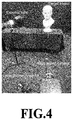
- Illustrative Embodiment 1 is an example in which an engraved sculpture is shot while irradiating a grid pattern onto the surface of the engraved sculpture as a target object under strong ambient light and the system displays (or reproduces) the image of the engraved sculpture including the grid pattern.
- FIG. 4 shows the layout during the measurement.
- a lamp simulating the ambient light (external light) is provided in front of the engraved sculpture (target object) in an oblique direction.
- a laser pattern projector for floodlighting the grid pattern to which the spread spectrum modulation according to the method of the present invention is applied, and a high speed camera (high speed camera) for shooting the engraved sculpture are further provided in front thereof.
- the laser pattern projector and the high speed camera are connected to a computer (PC) including a display so that the communication therebetween is achieved.
- the lamp is provided to have a distance of about 0.7 m from the engraved sculpture and has an output of 400 W and may irradiate light to the engraved sculpture at about 100K lux.
- the laser pattern projector is provided at a distance of about 1.7 m from the engraved sculpture and irradiates spectrum spread-modulated wave-like grid pattern light having a wavelength of about 800 nm to the surface of the engraved sculpture at the light intensity of about 40 mW.
- the high speed camera includes a bandpass filter that may receive light having a wavelength of about 800 nm and may shoot a 12-bit image of 512 ⁇ 512 pixels with 22500 FPS.
- FIGS. 5( a ) to 5( d ) illustrate a display image by the display showing the result of the measurement based on the above-described measurement conditions.
- (a) shows a shot image by the high speed camera obtained when the engraved sculpture is illuminated by the lamp at about 100 Klux while irradiating the spectrum spread-modulated wave-like grid pattern light thereto. No wave-like grid pattern may be visually recognized from the image.
- (b)-(c) illustrate display images obtained by processing the shot image by Steps S 3 -S 6 of the above-described image processing method of FIG. 2 .
- the wave-like grid pattern reflecting the surface shape of the engraved sculpture may be visually recognized. As may be seen, the wave-like grid pattern has visibility higher with an increase of the length L of the spreading code.
- Illustrative Embodiment 2 shows an example in which a rubber ball is shot while a grid pattern is irradiated, under sunlight, to the surface of a rubber ball (moving object) as a target object moving away from a hand and the system displays (or reproduces) an image including the grid pattern.
- the measurement was performed using the laser pattern projector and the high speed camera as in the case of Illustrative Embodiment 1 of FIG. 4 .
- the sunlight had a brightness of about 50 Klux.
- the spectrum spread-modulated wave-like grid pattern light having a wavelength of about 800 nm was irradiated to the rubber ball at the light intensity of about 85 mW.
- FIGS. 6( a ) to 6( e ) illustrate the display image by the display showing the measurement result.
- (a) illustrates shot images (raw images with no processing) at three instants of time obtained by shooting the moving rubber ball.
- (b) illustrates shot images at three instants of time obtained by irradiating the spectrum spread-modulated wave-like grid pattern light from the laser pattern projector. No wave-like grid pattern may be visually recognized from the images.
- (c) illustrates display images obtained by processing the shot images by Steps S 3 -S 6 of the above-described image processing method of FIG. 2 . However, the filtering processing of Step S 3 was not performed. A boundary between the rubber ball and the hand has therebetween undesirable images that should not exist (noise images due to the move).
- (d) illustrates the display images representing a result of processing shot images based on the above-mentioned image processing method of FIG. 2 , which includes filtering (processing by the high-pass filter). This indicates that the noise image caused by movement in (c) has been eliminated.
- (e) illustrates the three-dimensional (3D) images reconstructed based on the obtained demodulated images.
- Illustrative Embodiment 3 is an example when the image processing method of the present disclosure was applied to the photometric-stereo method.
- FIGS. 7( a ) and 7( b ) illustrate the measurement system.
- the camera lens is surrounded by 60 LEDs in a circular manner.
- the 60 LEDs adjacent to one another are assumed as one set to flash (ON or OFF).
- the LED flashing is performed using the flashing (modulation light) based on the spreading signal obtained by the spread spectrum modulation of the present disclosure.
- a camera including the LEDs is placed to have a distance of about 1.5 m from a duck ornament as a target object placed on a base.
- the duck ornament is illuminated with the 6 LEDs from the 10 directions, respectively.
- the duck ornament may be shot by a high speed camera.
- FIG. 8 illustrates the display image by the display showing the measurement result.
- the three images in (a) are reference images shot with a long exposure time under the condition that no ambient light exits.
- (b)-(d) illustrate the images obtained by processing, by the image processing method of the present invention, the images shot by a high speed camera while the LEDs lighted using a spread spectrum modulation signal.
- the right end images are a three-dimensional restored image.
- the three images are an image obtained without ambient light.
- (c) and (d) illustrate images obtained with ambient light.
- a high-pass filtering as the filtering was performed with the spatial filtering in addition to the high-pass filtering of (d). It would be understood that the reconstruction is successfully implemented such that the duck ornament is sufficiently visible even under the condition in which the ambient light of (c) and (d) exist.
- Illustrative Embodiment 4 illustrates an example when the embedded image embedded in the video image is displayed on the display of the computer (PC) based on the above-described image processing flow of FIG. 3 .
- the display was processed at a refresh rate of 60 Hz.
- (a) illustrates an input image (video image) in which the face of a baboon may be visually recognized.
- (c) illustrates an image frame when the embedded image was displayed using the spread spectrum modulation in which a black screen is displayed because the respective pixels of the display have a low brightness and thus the embedded image may not be visually recognized.
- (d) illustrates a demodulated image obtained when the input image of (a) that may be visually recognized and the embedded image of (c) that may not be visually recognized on the display are shot by the camera while allowing the images to slide in the left-and-right direction to thereby process the shot images by the method of the present invention. In this case, not only the high-pass filtering but also the spatial filtering were performed.
- the embedded image is displayed (or reproduced).
Landscapes
- Engineering & Computer Science (AREA)
- Physics & Mathematics (AREA)
- Theoretical Computer Science (AREA)
- General Physics & Mathematics (AREA)
- Signal Processing (AREA)
- Multimedia (AREA)
- Computer Vision & Pattern Recognition (AREA)
- Optics & Photonics (AREA)
- Computing Systems (AREA)
- Computer Networks & Wireless Communication (AREA)
- Human Computer Interaction (AREA)
- General Engineering & Computer Science (AREA)
- Image Processing (AREA)
- Studio Devices (AREA)
Abstract
Description
- PTL 1: Japanese Patent No. 5317169
- PTL 2: Japanese Patent No. 5761750
- PTL 3: International Publication WO2014/020823
- NPL 1: Proceedings of the Ninth IEEE International Conference on Computer Vision (ICCV'03)
- NPL 2: IEEE TRANSACTIONS ON IMAGE PROCESSING, VOL. 8, NO. 8, pp 1075-1083, AUGUST 1999
M 1(t k)F(s k) (1)
M 2(t k)=S(t−kT)·M 1(t k) (2)
Equation 3
M′ 2(t k)=M 2(t k)+n(t k) (3)
D(t k)=S′(t−kT)·M′ 2(t k) (4)
s′ k =F′(D(t k)) (5)
Equation 7
h(t)=ω(t)·IDFT(H(ω)) (7)
Equation 9
D(t,x,y)=S(t)·(h(t)*g(x,y)*M′ 2(t,x,y)) (9)
Equation 11
HSs=Hm (11)
s=(S T H T HS)−1 S T H T Hm. (12)
Equation 13
(Q T H T HQ)−1 Q T H T H, (13)
Q=[S j1 S j2 . . . S jM] (14)
-
- 1 Body (Object)
- 10 Light source
- 12 Imaging apparatus
- 14 Operation processing apparatus
- 100 Image processing system
Claims (13)
Applications Claiming Priority (4)
| Application Number | Priority Date | Filing Date | Title |
|---|---|---|---|
| JP2017-011501 | 2017-01-25 | ||
| JPJP2017-011501 | 2017-01-25 | ||
| JP2017011501 | 2017-01-25 | ||
| PCT/JP2018/000873 WO2018139237A1 (en) | 2017-01-25 | 2018-01-15 | Image processing method |
Publications (2)
| Publication Number | Publication Date |
|---|---|
| US20190387164A1 US20190387164A1 (en) | 2019-12-19 |
| US11076093B2 true US11076093B2 (en) | 2021-07-27 |
Family
ID=62978308
Family Applications (1)
| Application Number | Title | Priority Date | Filing Date |
|---|---|---|---|
| US16/479,370 Expired - Fee Related US11076093B2 (en) | 2017-01-25 | 2018-01-15 | Image processing method |
Country Status (5)
| Country | Link |
|---|---|
| US (1) | US11076093B2 (en) |
| EP (1) | EP3561447B1 (en) |
| JP (1) | JP6934645B2 (en) |
| CN (1) | CN110214262A (en) |
| WO (1) | WO2018139237A1 (en) |
Families Citing this family (2)
| Publication number | Priority date | Publication date | Assignee | Title |
|---|---|---|---|---|
| JP6898684B1 (en) * | 2020-11-17 | 2021-07-07 | 株式会社シンカ・アウトフィットNq | Analyst |
| JP2025010546A (en) * | 2021-11-29 | 2025-01-22 | コニカミノルタ株式会社 | Image forming system, image forming method, and program |
Citations (24)
| Publication number | Priority date | Publication date | Assignee | Title |
|---|---|---|---|---|
| JPS5317169B2 (en) | 1974-01-28 | 1978-06-06 | ||
| JPS5449191A (en) | 1977-09-26 | 1979-04-18 | Kobe Steel Ltd | Method of detecting surface flaw of hot steel |
| JPS5761750B2 (en) | 1971-12-03 | 1982-12-25 | Sumitomo Chemical Co | |
| JPS63109309A (en) | 1986-10-28 | 1988-05-14 | Tokai Rika Co Ltd | Non-contact flatness measuring device |
| JPH07325095A (en) | 1994-05-31 | 1995-12-12 | Sony Tektronix Corp | Rotation speed measuring device |
| JPH1141571A (en) | 1997-07-18 | 1999-02-12 | Sony Corp | Signal synthesizing device, signal synthesizing method, video signal recording device, video signal recording method, and recording medium |
| JPH11311510A (en) | 1998-04-27 | 1999-11-09 | Asahi Glass Co Ltd | Inspection method and inspection device for minute unevenness |
| JP2000269886A (en) | 1999-01-12 | 2000-09-29 | Toyota Motor Corp | Vehicle-to-vehicle communication device |
| US20020135467A1 (en) | 1999-01-12 | 2002-09-26 | Shin Koike | Positional data utilizing inter-vehicle communication method and traveling control apparatus |
| JP2003126786A (en) | 2001-10-23 | 2003-05-07 | Yamazaki Baking Co Ltd | Raisin detector with stem |
| JP2006322759A (en) | 2005-05-17 | 2006-11-30 | Nippon Signal Co Ltd:The | Optical sensor, and object detection device and optical communication device using it |
| JP2007164282A (en) | 2005-12-09 | 2007-06-28 | Tokai Rika Co Ltd | Touch type detection switch |
| JP2009245349A (en) | 2008-03-31 | 2009-10-22 | Namco Bandai Games Inc | Position detection system, program, information recording medium, and image generating device |
| US20110081072A1 (en) | 2008-06-13 | 2011-04-07 | Techno Dream 21 Co., Ltd. | Image processing device, image processing method, and program |
| JP2011142607A (en) | 2009-12-08 | 2011-07-21 | Shiseido Co Ltd | Invisible information embedding device, invisible information recognition device, invisible information embedding method, invisible information recognition method, invisible information embedding program, and invisible information recognition program |
| WO2011132241A1 (en) | 2010-04-23 | 2011-10-27 | パナソニック株式会社 | Image capture device |
| JP2011242183A (en) | 2010-05-17 | 2011-12-01 | Hiroshima City Univ | Image processing device, image processing method, and program |
| US20130335531A1 (en) * | 2011-02-28 | 2013-12-19 | Sharp Kabushiki Kaisha | Apparatus for projecting grid pattern |
| WO2014020823A1 (en) | 2012-07-30 | 2014-02-06 | 独立行政法人産業技術総合研究所 | Image processing system, and image processing method |
| JP2014195263A (en) | 2009-02-19 | 2014-10-09 | Sony Corp | Unit and method for processing image |
| US20150010201A1 (en) * | 2013-07-05 | 2015-01-08 | Thomson Licensing | Method and device for assessing the presence of a watermark in a video |
| JP2015200544A (en) | 2014-04-07 | 2015-11-12 | 株式会社神戸製鋼所 | Surface irregularity inspection device and surface irregularity inspection method |
| US20160109575A1 (en) * | 2013-06-06 | 2016-04-21 | Heptagon Micro Optics Pte. Ltd. | Sensor System With Active Illumination |
| US20160349359A1 (en) | 2015-05-27 | 2016-12-01 | Amir Nevet | Reduction in camera to camera interference in depth measurements using spread spectrum |
-
2018
- 2018-01-15 CN CN201880007740.4A patent/CN110214262A/en active Pending
- 2018-01-15 EP EP18744822.0A patent/EP3561447B1/en active Active
- 2018-01-15 JP JP2018564479A patent/JP6934645B2/en active Active
- 2018-01-15 US US16/479,370 patent/US11076093B2/en not_active Expired - Fee Related
- 2018-01-15 WO PCT/JP2018/000873 patent/WO2018139237A1/en not_active Ceased
Patent Citations (28)
| Publication number | Priority date | Publication date | Assignee | Title |
|---|---|---|---|---|
| JPS5761750B2 (en) | 1971-12-03 | 1982-12-25 | Sumitomo Chemical Co | |
| JPS5317169B2 (en) | 1974-01-28 | 1978-06-06 | ||
| JPS5449191A (en) | 1977-09-26 | 1979-04-18 | Kobe Steel Ltd | Method of detecting surface flaw of hot steel |
| JPS63109309A (en) | 1986-10-28 | 1988-05-14 | Tokai Rika Co Ltd | Non-contact flatness measuring device |
| JPH07325095A (en) | 1994-05-31 | 1995-12-12 | Sony Tektronix Corp | Rotation speed measuring device |
| JPH1141571A (en) | 1997-07-18 | 1999-02-12 | Sony Corp | Signal synthesizing device, signal synthesizing method, video signal recording device, video signal recording method, and recording medium |
| JPH11311510A (en) | 1998-04-27 | 1999-11-09 | Asahi Glass Co Ltd | Inspection method and inspection device for minute unevenness |
| JP2000269886A (en) | 1999-01-12 | 2000-09-29 | Toyota Motor Corp | Vehicle-to-vehicle communication device |
| US20020135467A1 (en) | 1999-01-12 | 2002-09-26 | Shin Koike | Positional data utilizing inter-vehicle communication method and traveling control apparatus |
| JP2003126786A (en) | 2001-10-23 | 2003-05-07 | Yamazaki Baking Co Ltd | Raisin detector with stem |
| JP2006322759A (en) | 2005-05-17 | 2006-11-30 | Nippon Signal Co Ltd:The | Optical sensor, and object detection device and optical communication device using it |
| JP2007164282A (en) | 2005-12-09 | 2007-06-28 | Tokai Rika Co Ltd | Touch type detection switch |
| JP2009245349A (en) | 2008-03-31 | 2009-10-22 | Namco Bandai Games Inc | Position detection system, program, information recording medium, and image generating device |
| US20110014982A1 (en) | 2008-03-31 | 2011-01-20 | Namco Bandai Games Inc. | Position detection system, position detection method, information storage medium, and image generation device |
| US20110081072A1 (en) | 2008-06-13 | 2011-04-07 | Techno Dream 21 Co., Ltd. | Image processing device, image processing method, and program |
| JP2014195263A (en) | 2009-02-19 | 2014-10-09 | Sony Corp | Unit and method for processing image |
| US20120237079A1 (en) | 2009-12-08 | 2012-09-20 | Naoto Hanyu | Invisible information embedding apparatus, invisible information detecting apparatus, invisible information embedding method, invisible information detecting method, and storage medium |
| JP2011142607A (en) | 2009-12-08 | 2011-07-21 | Shiseido Co Ltd | Invisible information embedding device, invisible information recognition device, invisible information embedding method, invisible information recognition method, invisible information embedding program, and invisible information recognition program |
| WO2011132241A1 (en) | 2010-04-23 | 2011-10-27 | パナソニック株式会社 | Image capture device |
| US20130002882A1 (en) * | 2010-04-23 | 2013-01-03 | Panasonic Corporation | Image-capturing device |
| JP2011242183A (en) | 2010-05-17 | 2011-12-01 | Hiroshima City Univ | Image processing device, image processing method, and program |
| US20130335531A1 (en) * | 2011-02-28 | 2013-12-19 | Sharp Kabushiki Kaisha | Apparatus for projecting grid pattern |
| WO2014020823A1 (en) | 2012-07-30 | 2014-02-06 | 独立行政法人産業技術総合研究所 | Image processing system, and image processing method |
| US20150221093A1 (en) | 2012-07-30 | 2015-08-06 | National Institute Of Advanced Industrial Science And Technolgy | Image processing system, and image processing method |
| US20160109575A1 (en) * | 2013-06-06 | 2016-04-21 | Heptagon Micro Optics Pte. Ltd. | Sensor System With Active Illumination |
| US20150010201A1 (en) * | 2013-07-05 | 2015-01-08 | Thomson Licensing | Method and device for assessing the presence of a watermark in a video |
| JP2015200544A (en) | 2014-04-07 | 2015-11-12 | 株式会社神戸製鋼所 | Surface irregularity inspection device and surface irregularity inspection method |
| US20160349359A1 (en) | 2015-05-27 | 2016-12-01 | Amir Nevet | Reduction in camera to camera interference in depth measurements using spread spectrum |
Non-Patent Citations (13)
| Title |
|---|
| Decision of Refusal dated Mar. 3, 2020, issued I Japanese Patent Application No. 2018/564479. |
| Decision of Refusal dated Mar. 3, 2020, issued in Japanese Patent Application No. 2018/564479. |
| International Preliminary Report on Patentability dated Jul. 30, 2019, issued in PCT Application No. PCT/JP2018/00873, filed Jan. 15, 2018. |
| International Search Report dated Mar. 13, 2018, issued in PCT Application No. PCT/JP2018/00873, filed Jan. 15, 2018. |
| Japanese Office Action dated Apr. 27, 2021, from Application No. 2018-564479. |
| Japanese Office Action, English Translation, for JP 2018-564479 filed Oct. 29, 2018, dated Feb. 2, 2021. |
| Lisa M. Marvel et al., Spread Spectrum Image Steganography, IEEE Transactions on Image Processing, vol. 8, No. 8, Aug. 1999, pp. 1075-1083. |
| MILLER W. T.: "VIDEO IMAGE STEREO MATCHING USING PHASE-LOCKED LOOP TECHNIQUES.", INTERNATIONAL CONFERENCE ON ROBOTICS AND AUTOMATION. SAN FRANCISCO, CALIFORNIA, APRIL 7-10, 1986., LOS ANGELES, I.E.E.E. COMPUTER SOC., US, vol. 01., 7 April 1986 (1986-04-07), US, pages 112 - 117., XP000319645 |
| Ryusuke Sagawa et al., Dense One-shot 3D Reconstruction by Detecting Continuous Regions with Parallel Line Projection, 2011 IEEE International Conference on Computer Vision, pp. 1911-1918. |
| Ryusuke Sagawa et al., Linear Solution for Oneshot Active 3D Reconstruction Using Multiple Projectors, In Proc. Fifth International Symposium on 3D Data Processing, Visualization and Transmission, May 2019, pp. 8. |
| Supplementary European Search Report dated Jul. 20, 2020, issued in EP Application No. 18744822.0. |
| W. Thomas Miller, III, Video Image Stereo Matching Using Phase-Locked Loop Techniques, IEEE, 1986, XP000319645, pp. 112-117. |
| Yoav Y. Schechner et al., A Therory of Multiplexed Illumination, Proceedings of the Ninth IEEE International Conference on Computer Vision (ICCV 2003) 2-vol. Set, 2003, pp. 8. |
Also Published As
| Publication number | Publication date |
|---|---|
| EP3561447A4 (en) | 2020-08-26 |
| US20190387164A1 (en) | 2019-12-19 |
| CN110214262A (en) | 2019-09-06 |
| EP3561447A1 (en) | 2019-10-30 |
| WO2018139237A1 (en) | 2018-08-02 |
| JP6934645B2 (en) | 2021-09-15 |
| JPWO2018139237A1 (en) | 2019-07-04 |
| EP3561447B1 (en) | 2023-11-22 |
Similar Documents
| Publication | Publication Date | Title |
|---|---|---|
| CN111345903B (en) | Image processing device, fluorescence observation device and method for simulating fluorescence observation device | |
| Froehlich et al. | Creating cinematic wide gamut HDR-video for the evaluation of tone mapping operators and HDR-displays | |
| US7044613B2 (en) | Realistic scene illumination reproduction | |
| Narasimhan et al. | Temporal dithering of illumination for fast active vision | |
| JP2011010258A (en) | Image processing apparatus, image display system, and image extraction device | |
| US20130307933A1 (en) | Method of recording an image and obtaining 3d information from the image, camera system | |
| WO2015098288A1 (en) | Image processing device and image processing method | |
| ATE209364T1 (en) | METHOD AND DEVICE FOR VIEWING AN IMAGE | |
| WO2014075062A4 (en) | System and method for 3-dimensional object rendering of a moving object using structured light patterns and moving window imagery | |
| EP2476296B1 (en) | Illumination system for enhancing the appearance of an object and method thereof | |
| US20180094919A1 (en) | Imaging system with synchronized dynamic control of directable beam light source and reconfigurably masked photo-sensor | |
| US11076093B2 (en) | Image processing method | |
| US20180077399A1 (en) | Image processing device, image processing method, and computer-readable recording medium | |
| Kubo et al. | Programmable non-epipolar indirect light transport: Capture and analysis | |
| CN103905738B (en) | High dynamic range images generate system and method | |
| JP7449459B1 (en) | Method and system for analyzing objects | |
| JP6292968B2 (en) | Pseudo HDR image estimation apparatus and method | |
| US20190072898A1 (en) | Full-color incoherent digital holography | |
| US20170287140A1 (en) | High quality Lightning resilient segmentation system using active background | |
| US10345681B2 (en) | Compressive imaging using structured illumination | |
| JP2011139115A (en) | High-speed camera equipment and image processing method for the same | |
| EP4217796A1 (en) | System for converting images into sound spectrum | |
| CN118433555B (en) | Backlight reduction for infrared images | |
| JP6326356B2 (en) | Imaging device and method of operating imaging device | |
| US12549841B2 (en) | Method and apparatus for performing spectral analysis of skin of a subject |
Legal Events
| Date | Code | Title | Description |
|---|---|---|---|
| AS | Assignment |
Owner name: NATIONAL INSTITUTE OF ADVANCED INDUSTRIAL SCIENCE Free format text: ASSIGNMENT OF ASSIGNORS INTEREST;ASSIGNOR:SAGAWA, RYUSUKE;REEL/FRAME:049801/0193 Effective date: 20190607 Owner name: NATIONAL INSTITUTE OF ADVANCED INDUSTRIAL SCIENCE AND TECHNOLOGY, JAPAN Free format text: ASSIGNMENT OF ASSIGNORS INTEREST;ASSIGNOR:SAGAWA, RYUSUKE;REEL/FRAME:049801/0193 Effective date: 20190607 |
|
| FEPP | Fee payment procedure |
Free format text: ENTITY STATUS SET TO UNDISCOUNTED (ORIGINAL EVENT CODE: BIG.); ENTITY STATUS OF PATENT OWNER: LARGE ENTITY |
|
| STPP | Information on status: patent application and granting procedure in general |
Free format text: NON FINAL ACTION MAILED |
|
| STPP | Information on status: patent application and granting procedure in general |
Free format text: DOCKETED NEW CASE - READY FOR EXAMINATION |
|
| STPP | Information on status: patent application and granting procedure in general |
Free format text: NON FINAL ACTION MAILED |
|
| STPP | Information on status: patent application and granting procedure in general |
Free format text: RESPONSE TO NON-FINAL OFFICE ACTION ENTERED AND FORWARDED TO EXAMINER |
|
| STPP | Information on status: patent application and granting procedure in general |
Free format text: NOTICE OF ALLOWANCE MAILED -- APPLICATION RECEIVED IN OFFICE OF PUBLICATIONS |
|
| STPP | Information on status: patent application and granting procedure in general |
Free format text: PUBLICATIONS -- ISSUE FEE PAYMENT RECEIVED |
|
| STPP | Information on status: patent application and granting procedure in general |
Free format text: PUBLICATIONS -- ISSUE FEE PAYMENT VERIFIED |
|
| STCF | Information on status: patent grant |
Free format text: PATENTED CASE |
|
| FEPP | Fee payment procedure |
Free format text: MAINTENANCE FEE REMINDER MAILED (ORIGINAL EVENT CODE: REM.); ENTITY STATUS OF PATENT OWNER: LARGE ENTITY |
|
| LAPS | Lapse for failure to pay maintenance fees |
Free format text: PATENT EXPIRED FOR FAILURE TO PAY MAINTENANCE FEES (ORIGINAL EVENT CODE: EXP.); ENTITY STATUS OF PATENT OWNER: LARGE ENTITY |
|
| STCH | Information on status: patent discontinuation |
Free format text: PATENT EXPIRED DUE TO NONPAYMENT OF MAINTENANCE FEES UNDER 37 CFR 1.362 |
|
| FP | Lapsed due to failure to pay maintenance fee |
Effective date: 20250727 |