EP2295877B1 - Air conditioner - Google Patents
Air conditioner Download PDFInfo
- Publication number
- EP2295877B1 EP2295877B1 EP10250770.4A EP10250770A EP2295877B1 EP 2295877 B1 EP2295877 B1 EP 2295877B1 EP 10250770 A EP10250770 A EP 10250770A EP 2295877 B1 EP2295877 B1 EP 2295877B1
- Authority
- EP
- European Patent Office
- Prior art keywords
- refrigerant
- distribution device
- hot gas
- air conditioner
- refrigerant distribution
- Prior art date
- Legal status (The legal status is an assumption and is not a legal conclusion. Google has not performed a legal analysis and makes no representation as to the accuracy of the status listed.)
- Active
Links
Images


Classifications
-
- F—MECHANICAL ENGINEERING; LIGHTING; HEATING; WEAPONS; BLASTING
- F25—REFRIGERATION OR COOLING; COMBINED HEATING AND REFRIGERATION SYSTEMS; HEAT PUMP SYSTEMS; MANUFACTURE OR STORAGE OF ICE; LIQUEFACTION SOLIDIFICATION OF GASES
- F25B—REFRIGERATION MACHINES, PLANTS OR SYSTEMS; COMBINED HEATING AND REFRIGERATION SYSTEMS; HEAT PUMP SYSTEMS
- F25B47/00—Arrangements for preventing or removing deposits or corrosion, not provided for in another subclass
- F25B47/02—Defrosting cycles
-
- F—MECHANICAL ENGINEERING; LIGHTING; HEATING; WEAPONS; BLASTING
- F24—HEATING; RANGES; VENTILATING
- F24F—AIR-CONDITIONING; AIR-HUMIDIFICATION; VENTILATION; USE OF AIR CURRENTS FOR SCREENING
- F24F1/00—Room units for air-conditioning, e.g. separate or self-contained units or units receiving primary air from a central station
- F24F1/06—Separate outdoor units, e.g. outdoor unit to be linked to a separate room comprising a compressor and a heat exchanger
- F24F1/26—Refrigerant piping
- F24F1/32—Refrigerant piping for connecting the separate outdoor units to indoor units
-
- F—MECHANICAL ENGINEERING; LIGHTING; HEATING; WEAPONS; BLASTING
- F24—HEATING; RANGES; VENTILATING
- F24F—AIR-CONDITIONING; AIR-HUMIDIFICATION; VENTILATION; USE OF AIR CURRENTS FOR SCREENING
- F24F11/00—Control or safety arrangements
- F24F11/89—Arrangement or mounting of control or safety devices
-
- F—MECHANICAL ENGINEERING; LIGHTING; HEATING; WEAPONS; BLASTING
- F25—REFRIGERATION OR COOLING; COMBINED HEATING AND REFRIGERATION SYSTEMS; HEAT PUMP SYSTEMS; MANUFACTURE OR STORAGE OF ICE; LIQUEFACTION SOLIDIFICATION OF GASES
- F25B—REFRIGERATION MACHINES, PLANTS OR SYSTEMS; COMBINED HEATING AND REFRIGERATION SYSTEMS; HEAT PUMP SYSTEMS
- F25B41/00—Fluid-circulation arrangements
- F25B41/20—Disposition of valves, e.g. of on-off valves or flow control valves
-
- F—MECHANICAL ENGINEERING; LIGHTING; HEATING; WEAPONS; BLASTING
- F25—REFRIGERATION OR COOLING; COMBINED HEATING AND REFRIGERATION SYSTEMS; HEAT PUMP SYSTEMS; MANUFACTURE OR STORAGE OF ICE; LIQUEFACTION SOLIDIFICATION OF GASES
- F25B—REFRIGERATION MACHINES, PLANTS OR SYSTEMS; COMBINED HEATING AND REFRIGERATION SYSTEMS; HEAT PUMP SYSTEMS
- F25B41/00—Fluid-circulation arrangements
- F25B41/40—Fluid line arrangements
-
- F—MECHANICAL ENGINEERING; LIGHTING; HEATING; WEAPONS; BLASTING
- F25—REFRIGERATION OR COOLING; COMBINED HEATING AND REFRIGERATION SYSTEMS; HEAT PUMP SYSTEMS; MANUFACTURE OR STORAGE OF ICE; LIQUEFACTION SOLIDIFICATION OF GASES
- F25B—REFRIGERATION MACHINES, PLANTS OR SYSTEMS; COMBINED HEATING AND REFRIGERATION SYSTEMS; HEAT PUMP SYSTEMS
- F25B45/00—Arrangements for charging or discharging refrigerant
-
- F—MECHANICAL ENGINEERING; LIGHTING; HEATING; WEAPONS; BLASTING
- F24—HEATING; RANGES; VENTILATING
- F24F—AIR-CONDITIONING; AIR-HUMIDIFICATION; VENTILATION; USE OF AIR CURRENTS FOR SCREENING
- F24F11/00—Control or safety arrangements
- F24F11/30—Control or safety arrangements for purposes related to the operation of the system, e.g. for safety or monitoring
- F24F11/41—Defrosting; Preventing freezing
- F24F11/42—Defrosting; Preventing freezing of outdoor units
-
- Y—GENERAL TAGGING OF NEW TECHNOLOGICAL DEVELOPMENTS; GENERAL TAGGING OF CROSS-SECTIONAL TECHNOLOGIES SPANNING OVER SEVERAL SECTIONS OF THE IPC; TECHNICAL SUBJECTS COVERED BY FORMER USPC CROSS-REFERENCE ART COLLECTIONS [XRACs] AND DIGESTS
- Y02—TECHNOLOGIES OR APPLICATIONS FOR MITIGATION OR ADAPTATION AGAINST CLIMATE CHANGE
- Y02B—CLIMATE CHANGE MITIGATION TECHNOLOGIES RELATED TO BUILDINGS, e.g. HOUSING, HOUSE APPLIANCES OR RELATED END-USER APPLICATIONS
- Y02B30/00—Energy efficient heating, ventilation or air conditioning [HVAC]
Definitions
- the present invention relates to an air conditioner, and more particularly, to an air conditioner adapted for defrosting an outdoor heat exchanger using hot gas.
- an air conditioner is an apparatus for cooling or heating indoor using a refrigeration cycle including a compressor, an outdoor heat exchanger, an expansion device, and an indoor heat exchanger. That is, the air conditioner can be formed as a cooler for cooling indoor or as a heater for heating indoor. The air conditioner can be formed as an air conditioner for both cooling and heating for cooling or heating indoor.
- the air conditioner may include a 4-way valve for changing a flow path of a refrigerant compressed in a compressor according to a cooling operation and a heating operation. That is, when a cooling operation is performed, a refrigerant compressed in the compressor is flowed to an outdoor heat exchanger by passing through a 4-way valve, and the outdoor heat exchanger functions as a condenser. A refrigerant condensed in the outdoor heat exchanger is expanded in the expansion device and is injected into an indoor heat exchanger. In this case, the indoor heat exchanger functions as an evaporator, and a refrigerant evaporated in the indoor heat exchanger is injected into the compressor by passing through again the 4-way valve.
- a refrigerant compressed in the compressor flows to the indoor heat exchanger by passing through the 4-way valve, and the indoor heat exchanger functions as a condenser.
- a refrigerant condensed in the indoor heat exchanger is expanded in the expansion device and is injected into the outdoor heat exchanger.
- the outdoor heat exchanger functions as an evaporator, and a refrigerant evaporated in the outdoor heat exchanger is injected into the compressor by passing through again the 4-way valve.
- water is generated on a surface of a heat exchanger acting as an evaporator while operating, and water is generated on the surface of an indoor heat exchanger in a case of a cooling operation and water is generated on a surface of an outdoor heat exchanger in a case of a heating operation.
- a heating operation upon performing a heating operation, when condensed water generated on a surface of the outdoor heat exchanger is frozen, a smooth flow and heat exchange of outdoor air are disturbed, thereby deteriorating heating performance.
- US 4,407,137 discloses promoting effective heat transfer between refrigerant flowing through a heat exchanger and air flowing thereover using a headering arrangement such that during defrost a portion of the heat exchanger is isolated.
- US 2006/0144060 discloses a heat exchanger liquid refrigerant defrost system to defrost the coil subsystems used on an outdoor hear exchanger.
- the present invention has been made in an effort to solve the above problems, and the present invention provides an air conditioner that can effectively perform division defrost of an outdoor heat exchanger and effectively remove the remaining frost of a central part of the outdoor heat exchanger.
- the invention provides an air conditioner as set out in claim 1.
- the communication pipe may connect a lowest branch pipe of the branch pipes of the first refrigerant distribution device and an uppermost branch pipe of the branch pipes of the second refrigerant distribution device.
- the air conditioner may further include a third refrigerant distribution device connected to all of the plurality of refrigerant tubes using the branch pipe.
- the air conditioner may further include: compressors for compressing a refrigerant; hot gas pipes for connecting outlets of the compressors and inlets of the first and second refrigerant distribution devices, respectively; a first hot gas valve for adjusting hot gas flowing from the outlet of the compressor to the first refrigerant distribution device through the hot gas pipe; and a second hot gas valve for adjusting hot gas flowing from the outlet of the compressor to the second refrigerant distribution device through the hot gas pipe.
- the hot gas pipes may connect the outlets of the compressors and the inlet of the first and second refrigerant distribution devices based on when performing a heating operation of the air conditioner.
- the air conditioner may further include: a first expansion valve for intercepting injection of a refrigerant to the first refrigerant distribution device when hot gas is injected through the first hot gas valve; and a second expansion valve for intercepting injection of a refrigerant to the second refrigerant distribution device when hot gas is injected through the second hot gas valve.
- the hot gas pipes may include: a sharing hot gas pipe connected to a cooling/heating switching valve connection pipe between a cooling/heating switching valve for switching cooling/heating and the compressors; a first refrigerant distribution device connection pipe for connecting the sharing hot gas pipe and the inlet of the first refrigerant distribution device; and a second refrigerant distribution device connection pipe for connecting the sharing hot gas pipe and the inlet of the second refrigerant distribution device.
- the first expansion valve may be installed in the first refrigerant distribution device connection pipe, and the second expansion valve may be installed in the second refrigerant distribution device connection pipe.
- FIG. 1 is a perspective view illustrating an air conditioner according to an exemplary embodiment of the present invention.
- the air conditioner according to the present exemplary embodiment includes a plurality of indoor devices 1 to 4 and an outdoor device 5 connected to the plurality of indoor devices 1 to 4 and is formed as a multi-type heat pump air conditioner for selectively cooling and heating.
- a liquid pipe through which a liquid refrigerant passes and a gas pipe through which a gas refrigerant passes are connected in parallel.
- Each of the plurality of indoor devices 1 to 4 includes an indoor heat exchanger 11 for cooling or heating indoor air while a refrigerant exchanges heat with the indoor air, an indoor ventilator 12 for inhaling indoor air into the indoor devices 1 to 4, exchanging heat with the indoor heat exchanger 11, and discharging the indoor air to the outside of the indoor devices 1 to 4, and an indoor expansion device 13 for expanding a refrigerant flowed toward the indoor heat exchanger 11.
- the indoor expansion device 13 is formed with an electronic expansion valve such as LEV or EEV that can adjust expansion of a refrigerant.
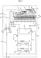
- FIG. 2 is a schematic diagram illustrating a refrigerant flow of an outdoor device when performing a cooling operation of an air conditioner according to an exemplary embodiment of the present invention
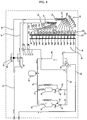
- FIG. 3 is a schematic diagram illustrating a refrigerant flow of an outdoor device when performing a heating operation of an air conditioner according to an exemplary embodiment of the present invention
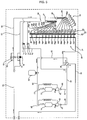
- FIG. 4 is a schematic diagram illustrating a refrigerant flow of an outdoor device when performing defrost in an upper part/evaporation in a lower part in an outdoor heat exchanger of an air conditioner according to an exemplary embodiment of the present invention
- FIG. 5 is a schematic diagram illustrating a refrigerant flow of an outdoor device when performing defrost in a lower part /evaporation in an upper part in an outdoor heat exchanger of an air conditioner according to an exemplary embodiment of the present invention.
- the air conditioner includes compressors 22 and 24, a cooling/heating switching valve 38, an outdoor heat exchanger 42, outdoor expansion devices 58 and 60, hot gas pipes 70, 71, and 72, and hot gas valves 74 and 76.
- the compressors 22 and 24 compress a refrigerant, are provided in plural, and in the compressors 22 and 24, refrigerant flow paths are connected in parallel.
- One of the compressors 22 and 24 is formed as a capacity variable compressor 22 such as an inverter compressor and the other one is formed as a constant speed compressor 24.
- inhalation pipes 26, 27, and 28 are connected to an accumulator 30, and the inhalation pipes 26, 27, and 28 include an accumulator connection pipe 26 connected to the accumulator 30 and compressor inhalation pipes 27 and 28 for connecting the accumulator connection pipe 26 and the inhalation side of the compressors 22 and 24.
- discharge pipes 31, 32, and 33 are connected to one cooling/heating switching valve 38, and the discharge pipes 31, 32, and 33 include compressor discharge pipes 31 and 32 connected to the discharge side of the compressors 22 and 24 and a cooling/heating switching valve connection pipe 33 for connecting the compressor discharge pipes 31 and 32 and the cooling/heating switching valve 38.
- oil separators 34 and 35 for separating oil from a refrigerant and oil discharged from the compressors 22 and 24 and for recovering the oil to the inhalation pipes 26, 27, and 28 and check valves 36 and 37 for preventing flowing backward of a refrigerant passing through the oil separators 34 and 35 are installed.
- the cooling/heating switching valve 38 guides a refrigerant compressed in the compressors 22 and 24 to the outdoor heat exchanger 42 and guides a refrigerant flowed in the indoor devices 1 to 4 to the accumulator 30 upon performing a cooling operation, and guides a refrigerant compressed in the compressors 22 and 24 to the indoor devices 1 to 4 and guides a refrigerant flowed in the outdoor heat exchanger 42 to the accumulator 30 upon performing a heating operation and is connected to the compressors 22 and 24 using the discharge pipes 31, 32, and 33, is connected to the accumulator 30 using an accumulator connection pipe 39, is connected to the indoor heat exchanger 11 using an indoor heat exchanger connection pipe 40, and is connected to the outdoor heat exchanger 42 using an outdoor heat exchanger connection pipe 41.
- the outdoor heat exchanger 42 is an evaporator/condenser for evaporating a refrigerant while exchanging heat of the refrigerant and outdoor air upon performing a cooling operation and for condensing a refrigerant while exchanging heat of the refrigerant and outdoor air upon performing a heating operation.
- the outdoor heat exchanger 42 includes an outdoor heat exchange unit 43 in which a refrigerant exchanges heat, first and second refrigerant distribution devices 44 and 46 for distributing a refrigerant to the outdoor heat exchange unit 43 upon performing a heating operation and for guiding to collect a refrigerant passing through the outdoor heat exchange unit 43 upon performing a cooling operation, and a third refrigerant distribution device 48 for guiding to collect a refrigerant passing through the outdoor heat exchange unit 43 upon performing a heating operation and for distributing a refrigerant to the outdoor heat exchange unit 43 upon performing a cooling operation.
- the outdoor heat exchanger 42 is formed to inject a refrigerant of different temperatures into an upper part and a lower part of the outdoor heat exchange unit 43 by the first and second refrigerant distribution devices 44 and 46 upon performing a heating operation and is formed to inject a refrigerant of the same temperature into an upper part and a lower part of the outdoor heat exchange unit 43 by the third refrigerant distribution device 48 upon performing a cooling operation.
- a plurality of refrigerant tubes 50 are disposed to be separated in a plurality of columns in a vertical direction to exchange heat of a refrigerant and outdoor air, and a plurality of electric heating pins 52 are connected to the plurality of refrigerant tubes 50.
- branch pipes 44a, 44b, 44c, 44d, 44e, 44f, and 44g are connected to a plurality of refrigerant tubes 50a, 50b, 50c, 50d, 50e, 50f, and 50g of an upper part of the plurality of refrigerant tubes 50.
- the first refrigerant distribution device 44 further includes a first distribution device body 45 to which the plurality of branch pipes 44a, 44b, 44c, 44d, 44e, 44f, and 44g of the first refrigerant distribution device 44 are connected.
- branch pipes 46a, 46b, 46c, 46d, 46e, 46f, and 46g are connected to a plurality of refrigerant tubes 50h, 50i, 50j, 50k, 501, 50m, and 50n, respectively, of a lower part of the plurality of refrigerant tubes 50.
- the second refrigerant distribution device 46 further includes a second distribution device body 47 to which the plurality of branch pipes 46a, 46b, 46c, 46d, 46e, 46f, and 46g of the second refrigerant distribution device 46 are connected.
- refrigerant pipes 54, 55, and 56 are connected in parallel so that a refrigerant flowed in the plurality of refrigerant tubes 50 of the outdoor heat exchange unit 43 flows to the indoor devices 1 to 4 upon performing a cooling operation and a refrigerant flowed in the indoor devices 1 to 4 flows to the plurality of refrigerant tubes 50 of the outdoor heat exchange unit 43 upon performing a heating operation.
- the refrigerant pipes 54, 55, and 56 include an indoor device connection pipe 54 connected to the indoor devices 1 to 4, a first distribution device body connection pipe 55 connected to the indoor device connection pipe 54 and the first distribution device body 45, and a second distribution device body connection pipe 56 connected to the indoor device connection pipe 54 and the second distribution device body 47.
- the third refrigerant distribution device 48 further includes a third distribution device body 49 to which the plurality of branch pipes 48a, 48b, 48c, 48d, 48e, 48f, 48g, 48h, 48i, 48j, 48k, 481, 48m, and 48n of the third refrigerant distribution device 48 are connected.
- the third distribution device body 49 is connected to the outdoor heat exchanger connection pipe 41 so that a refrigerant flowed from the cooling/heating switching valve 38 flows to the plurality of refrigerant tubes 50 of the outdoor heat exchange unit 43 upon performing a cooling operation and a refrigerant flowed from the plurality of refrigerant tubes 50 of the outdoor heat exchange unit 43 flows to the cooling/heating switching valve 38 upon performing a heating operation.
- the outdoor expansion devices 58 and 60 include a first expansion valve 58 for expanding a refrigerant flowing toward the first refrigerant distribution device 44 or for intercepting injection of a refrigerant to the first refrigerant distribution device 44 and a second expansion valve 60 for expanding a refrigerant flowing toward the second refrigerant distribution device 46 or for intercepting injection of a refrigerant to the second refrigerant distribution device 46.
- the first expansion valve 58 is installed in the first distribution device body connection pipe 55.
- the first expansion valve 58 is controlled so that a refrigerant injected from the indoor devices 1 to 4 does not flow to the first refrigerant distribution device 44.
- a first expanding valve 59 is connected parallel to the first expansion valve 58 so that a refrigerant flowed from the outdoor heat exchanger 42 bypasses the first expansion valve 58.
- the second expansion valve 60 is installed in the second distribution device body connection pipe 56.
- the second expansion valve 60 is controlled so that a refrigerant injected from the indoor devices 1 to 4 does not flow to the second refrigerant distribution device 46.
- a second expanding valve 61 is connected parallel to the second expansion valve 60 so that a refrigerant flowed from the outdoor heat exchanger 42 bypasses the second expansion valve 60.
- Hot gas pipes 70, 71, and 72 are installed to connect an outlet of the compressors 22 and 24 and inlets of the first and second refrigerant distribution devices 44 and 46 based on when performing a heating operation of the air conditioner.
- the hot gas pipes 70, 71, and 72 include a sharing hot gas pipe 70 connected to a refrigerant pipe, particularly the cooling/heating switching valve connection pipe 33, between the compressors 22 and 24 and the cooling/heating switching valve 38, a first refrigerant distribution device connection pipe 71 for connecting the sharing hot gas pipe 70 and an inlet of the first refrigerant distribution device 44, and a second refrigerant distribution device connection pipe 72 for connecting the sharing hot gas pipe 70 and an inlet of the second refrigerant distribution device 46.
- a first hot gas valve 74 for adjusting hot gas flowing from an outlet of the compressors 22 and 24 to the first refrigerant distribution device 44 through the hot gas pipes 70 and 71 and a second hot gas valve 76 for adjusting hot gas flowing from an outlet of the compressors 22 and 24 to the second refrigerant distribution device 46 through the hot gas pipes 70 and 72 are installed.
- the first hot gas valve 74 is installed in the first refrigerant distribution device connection pipe 71.
- the first hot gas valve 74 is opened when defrosting an upper part of the outdoor heat exchanger 42 and is closed in a case other than when defrosting an upper part of the outdoor heat exchanger 42.
- the second hot gas valve 76 is installed in the second refrigerant distribution device connection pipe 72.
- the second hot gas valve 76 is opened when defrosting a lower part of the outdoor heat exchanger 42 and is closed in a case other than when defrosting a lower part of the outdoor heat exchanger 42.
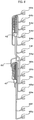
- the air conditioner according to the present exemplary embodiment further includes a communication pipe 80 for communicating one 44g of the branch pipes 44a, 44b, 44c, 44d, 44e, 44f, and 44g of the first refrigerant distribution device 44 and one 46a of the branch pipes 46a, 46b, 46c, 46d, 46e, 46f, and 46g of the second refrigerant distribution device 46.
- FIG. 6 is an enlarged perspective view illustrating first and second refrigerant distribution devices shown in FIGS. 2 to 5 .
- the communication pipe 80 is installed to connect the lowest branch pipe 44g of the branch pipes 44a, 44b, 44c, 44d, 44e, 44f, and 44g of the first refrigerant distribution device 44 and the uppermost branch pipe 46a of the branch pipes 46a, 46b, 46c, 46d, 46e, 46f, and 46g of the second refrigerant distribution device 46.
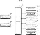
- FIG. 7 is a block diagram illustrating a control process of an air conditioner according to an exemplary embodiment of the present invention.
- the air conditioner includes a control panel 90 for manipulating the air conditioner, a temperature sensor 92 for determining a defrost condition of the outdoor heat exchanger 42, and a controller 94 for controlling the compressors 22 and 24 and the cooling/heating switching valve 38 according to a cooling/heating operation manipulated through the control panel 90 and for performing a heating/defrost operation according to a defrost condition such as a temperature detected in the temperature sensor 92 when performing a heating operation.
- a control panel 90 for manipulating the air conditioner
- a temperature sensor 92 for determining a defrost condition of the outdoor heat exchanger 42
- a controller 94 for controlling the compressors 22 and 24 and the cooling/heating switching valve 38 according to a cooling/heating operation manipulated through the control panel 90 and for performing a heating/defrost operation according to a defrost condition such as a temperature detected in the temperature sensor 92 when performing a heating operation.
- the temperature sensor 92 may be formed with an upper temperature sensor installed in an upper part of the outdoor heat exchanger 42 and a lower temperature sensor installed in a lower part of the outdoor heat exchanger 42 and may be formed with one temperature sensor installed in one of an upper part and a lower part of the outdoor heat exchanger 42.
- the controller 94 determines whether frost is generated according to a temperature value detected in the upper temperature sensor and the lower temperature sensor, determines whether defrost is complete, and determines whether frost is generated and determines whether defrost is complete according to a temperature value detected in one temperature sensor.
- the controller 94 may determine whether frost is performed in consideration of both a temperature value detected in the temperature sensor 92 and a sum time period of a heating operation, may determine whether frost is performed in consideration of only one of a temperature value detected in the temperature sensor 92 and a sum time period of a heating operation, and may use various defrost conditions.
- the controller 94 controls a mode of the cooling/heating switching valve 38 to a cooling mode upon performing a cooling operation and controls a mode of the first and second hot gas valves 74 and 76 to a close mode.
- the controller 94 controls a mode of the cooling/heating switching valve 38 to a heating mode upon performing a heating operation and controls a mode of the first and second hot gas valves 74 and 76 to a close mode.
- the controller 94 sustains the cooling/heating switching valve 38 in a present state, which is a heating mode, and controls the first expansion valve 58 to be in a close mode while controlling the first hot gas valve 74 to be in an opening mode, and if a predetermined time period has elapsed or if a temperature detected in the temperature sensor 92 rises a defrost release temperature or more of an upper part, the controller 94 controls the first expansion valve 58 to be in an opening mode while controlling the first hot gas valve 74 to be in a close mode and controls the second expansion valve 76 to be in a close mode while controlling the second expansion valve 76 to be in an opening mode.
- the compressors 22 and 24 are driven, the cooling/heating switching valve 38 is controlled to a cooling mode, the first and second hot gas valves 74 and 76 are controlled to a close mode, and a refrigerant compressed in the compressors 22 and 24 flows to the cooling/heating switching valve 38 instead of flowing to the first and second hot gas pipes 70, 71, and 72, as shown in FIG. 2 .
- a refrigerant flowed to the cooling/heating switching valve 38 is distributed and condensed to all of the plurality of refrigerant tubes 50 through the third refrigerant distribution device 48, and a refrigerant condensed while passing through the plurality of refrigerant tubes 50a, 50b, 50c, 50d, 50e, 50f, and 50g of an upper part of the plurality of refrigerant tubes 50 is flowed to the first refrigerant distribution device 44, and a refrigerant condensed while passing through the plurality of refrigerant tubes 50h, 50i, 50j, 50k, 501, 50m, and 50n of a lower part of the plurality of refrigerant tubes 50 is flowed to the second refrigerant distribution device 46.
- a refrigerant flowed to the first refrigerant distribution device 44 and the second refrigerant distribution device 46 is gathered in the refrigerant pipes 54, 55, and 56 and is flowed to the indoor devices 1 to 4.
- the refrigerant flowed to the indoor devices 1 to 4 is expanded in the indoor expansion device 13, is evaporated in the indoor heat exchanger 11, is flowed to the outdoor device 5, and is circulated to the compressors 22 and 24 after sequentially passing through the cooling/heating switching valve 38 and the accumulator 30.
- the compressors 22 and 24 are driven, the cooling/heating switching valve 38 is controlled to a heating mode, the first and second hot gas valves 74 and 76 are controlled to a close mode, and a refrigerant compressed in the compressors 22 and 24 flows to the cooling/heating switching valve 38 instead of flowing to the first and second hot gas pipes 70, 71, and 72, as shown in FIG. 3 .
- the refrigerant flowed to the cooling/heating switching valve 38 is flowed to the indoor devices 1 to 4 to be condensed in the indoor heat exchanger 13, is moved to the outdoor device 5 to be distributed, is expanded in the first and second expansion valves 58 and 60, is condensed while passing through the plurality of refrigerant tubes 50a, 50b, 50c, 50d, 50e, 50f, and 50g of an upper part of the plurality of refrigerant tubes 50 through the first refrigerant distribution device 44, and is condensed while passing through the plurality of refrigerant tubes 50h, 50i, 50j, 50k, 501, 50m, and 50n of a lower part of the plurality of refrigerant tubes 50 through the second refrigerant distribution device 46.
- the condensed refrigerant is gathered in the third refrigerant distribution device 48 and is circulated to the compressors 22 and 24 after sequentially passing through the cooling/heating switching valve 38 and the accumulator 30.
- the controller 94 While performing a heating operation, if a defrost condition is obtained, the controller 94 controls the first expansion valve 58 to be in a close mode while controlling the first hot gas valve 74 to be in an opening mode.
- some of a refrigerant compressed in the compressors 22 and 24 flows to the first refrigerant distribution device 44 after passing through the hot gas pipes 70 and 71 and the first hot gas valve 74, and the remaining portion of the refrigerant is condensed while passing through the indoor devices 1 to 4 after passing through the cooling/heating switching valve 38 and flows to the second refrigerant distribution device 46 after being expanded while passing through the second expansion valve 60, as in a heating operation.
- most of hot gas flowed to the first refrigerant distribution device 44 flows to the plurality of refrigerant tubes 50a, 50b, 50c, 50d, 50e, 50f, and 50g of an upper part of the plurality of refrigerant tubes 50 through the branch pipes 44a, 44b, 44c, 44d, 44e, 44f, and 44g of the first refrigerant distribution device 44, and some of hot gas flows to the uppermost branch pipe 46a of the second refrigerant distribution device 46 through the communication pipe 80.
- the expanded refrigerant flowed to the second refrigerant distribution device 46 flows to the branch pipes 46a, 46b, 46c, 46d, 46e, 46f, and 46g of the second refrigerant distribution device 46, and an expanded refrigerant flowing to the uppermost branch pipe 46a is mixed with hot gas injected through the communication pipe 80.
- defrost is performed and in refrigerant tubes 50i, 50j, 50k, 501, 50m, and 50n other than the uppermost refrigerant tube 50h of the plurality of refrigerant tubes 50h, 50i, 50j, 50k, 501, 50m, and 50n of a lower part, evaporation is performed while a refrigerant of a low temperature flows, while a refrigerant (mixed refrigerant of hot gas and an expanded refrigerant) of a temperature relatively higher than the plurality of refrigerant tubes 50h, 50i, 50j, 50k, 501, 50m, and 50n of a lower part flows, defrost is performed.
- the uppermost refrigerant tube 50h of the plurality of refrigerant tubes 50h, 50i, 50j, 50k, 501, 50m, and 50n of a lower part as well as the plurality of refrigerant tubes 50a, 50b, 50c, 50d, 50e, 50f, and 50g of an upper part are defrosted together, and in the outdoor heat exchanger 42, while an upper part and a central part are defrosted together, a lower part functions as an evaporator.
- the refrigerant passing through the plurality of refrigerant tubes 50 is gathered in the third refrigerant distribution device 48 and is circulated to the compressors 22 and 24 through the cooling/heating switching valve 38 and the accumulator 30.
- the controller 94 controls the first expansion valve 58 to be in an opening mode while controlling the first hot gas valve 74 to be in a close mode and controls the second expansion valve 60 to be in a close mode while controlling the second hot gas valve 76 to be in an opening mode.
- some of a refrigerant compressed in the compressors 22 and 24 flows to the second refrigerant distribution device 46 after passing through the hot gas pipes 70 and 72 and the second hot gas valve 76, and the remaining portion is condensed while passing through the indoor devices 1 to 4 after passing through the cooling/heating switching valve 38 and flows to the first refrigerant distribution device 44 after being expanded while passing through the first expansion valve 58, as in a heating operation.
- most of hot gas flowed to the second refrigerant distribution device 46 flows to the plurality of refrigerant tubes 50h, 50i, 50j, 50k, 501, 50m, and 50n of a lower part of the plurality of refrigerant tubes 50 through the branch pipes 46a, 46b, 46c, 46d, 46e, 46f, and 46g of the second refrigerant distribution device 46, and some thereof flows to the lowest branch pipe 44g of the first refrigerant distribution device 44 through the communication pipe 80.
- An expanded refrigerant flowed to the first refrigerant distribution device 44 flows to the branch pipes 44a, 44b, 44c, 44d, 44e, 44f, and 44g of the first refrigerant distribution device 44, and an expanded refrigerant flowing to the lowest branch pipe 44g is mixed with hot gas injected through the communication pipe 80.
- the lowest refrigerant tube 50g of the plurality of refrigerant tubes 50a, 50b, 50c, 50d, 50e, 50f, and 50g of an upper part as well as the plurality of refrigerant tubes 50h, 50i, 50j, 50k, 50l, 50m, and 50n of a lower part are defrosted together, and thus in the outdoor heat exchanger 42, while the lower part and the central part are defrosted together, an upper part functions as an evaporator.
- a refrigerant passing through the plurality of refrigerant tubes 50 is gathered in the third refrigerant distribution device 48 and then is circulated to the compressors 22 and 24 through the cooling/heating switching valve 38 and the accumulator 30.
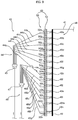
- FIG. 8 is an enlarged schematic diagram illustrating a refrigerant flow of an outdoor device when performing defrost of an upper part/evaporation of a lower part of an outdoor heat exchanger of an air conditioner according to another example
- FIG. 9 is an enlarged schematic diagram illustrating refrigerant flow of the outdoor device of figure 8 when performing defrost of a lower part/evaporation of the upper part of the outdoor heat exchanger.
- a first refrigerant distribution device 44 and a second refrigerant distribution device 46 are connected differently from those of an exemplary embodiment of the present invention, and other configurations other than the first refrigerant distribution device 44 and the second refrigerant distribution device 46 and operation thereof are equal to or similar to that of an exemplary embodiment of the present invention, and therefore a detailed description thereof will be omitted.
- branch pipes 44a, 44b, 44c, 44d, 44e, and 44f are connected to refrigerant tubes 50a, 50b, 50c, 50d, 50e, and 50f, respectively, other than a lowest refrigerant tube 50g of the plurality of refrigerant tubes 50a, 50b, 50c, 50d, 50e, 50f, and 50g of an upper part of a plurality of refrigerant tubes 50, and a branch pipe 44g is connected to an uppermost refrigerant tube 50h of a plurality of refrigerant tubes 50h, 50i, 50j, 50k, 50l, 50m, and 50n of a lower part of the plurality of refrigerant tubes 50.
- branch pipes 46b, 46c, 46d, 46e, 46f, and 46g are connected to refrigerant tubes 50i, 50j, 50k, 50l, 50m, and 50n, respectively, other than an uppermost refrigerant tube 50h of a plurality of refrigerant tubes 50h, 50i, 50j, 50k, 50l, 50m, and 50n of a lower part of the plurality of refrigerant tubes 50, and the branch pipe 46a is connected to a lowest refrigerant tube 50g of a plurality of refrigerant tubes 50a, 50b, 50c, 50d, 50e, 50f, and 50g of an upper part of the plurality of refrigerant tubes 50.
- the lowest branch pipe 44g of the first refrigerant distribution device 44 according to the present example and the uppermost branch pipe 46a of the second refrigerant distribution device 46 are connected to deviate from each other.
- most of hot gas flowed to the first refrigerant distribution device 44 flow to the plurality of refrigerant tubes 50a, 50b, 50c, 50d, 50e, and 50f of an upper part of the plurality refrigerant tubes 50 through the branch pipes 44a, 44b, 44c, 44d, 44e, and 44f of the first refrigerant distribution device 44 and some thereof flows to the uppermost refrigerant tube 50h of the plurality of refrigerant tubes 50h, 50i, 50j, 50k, 501, 50m, and 50n of a lower part through the branch pipe 44g.
- the refrigerant tubes 50a, 50b, 50c, 50d, 50e, and 50f other than the lowest refrigerant tube 50g of the plurality of refrigerant tubes 50a, 50b, 50c, 50d, 50e, 50f, and 50g of an upper part and defrost is performed while a refrigerant of a high temperature flows to the uppermost refrigerant tube 50h of the plurality of refrigerant tubes 50h, 50i, 50j, 50k, 501, 50m, and 50n of a lower part.
- Evaporation is performed while a refrigerant of a lower temperature flows to the refrigerant tubes 50i, 50j, 50k, 501, 50m, and 50n other than the uppermost refrigerant tube 50h of the plurality of refrigerant tubes 50h, 50i, 50j, 50k, 501, 50m, and 50n of a lower part and to the lowest refrigerant tube 50g of the plurality of refrigerant tubes 50a, 50b, 50c, 50d, 50e, 50f, and 50g of an upper part.
- most of the plurality of refrigerant tubes 50a, 50b, 50c, 50d, 50e, and 50f of an upper part and the uppermost refrigerant tube 50h of the plurality of refrigerant tubes 50h, 50i, 50j, 50k, 501, 50m, and 50n of a lower part are defrosted together and while an upper part and a central part of the outdoor heat exchanger 42 are defrosted together, a lower part thereof functions as an evaporator.
- the outdoor heat exchanger 42 when performing defrost in a lower part/evaporation in an upper part, while hot gas flows to the refrigerant tubes 50i, 50j, 50k, 501, 50m, and 50n other than the uppermost refrigerant tube 50h of the plurality of refrigerant tubes 50h, 50i, 50j, 50k, 501, 50m, and 50n of a lower part and to the lowest refrigerant tube 50g of the plurality of refrigerant tubes 50a, 50b, 50c, 50d, 50e, 50f, and 50g of an upper part, defrost is performed.
- Evaporation is performed while an expanded refrigerant flows to the refrigerant tubes 50a, 50b, 50c, 50d, 50e, and 50f other than the lowest refrigerant tube 50g of the plurality of refrigerant tubes 50a, 50b, 50c, 50d, 50e, 50f, and 50g of an upper part and to the uppermost refrigerant tube 50h of the plurality of refrigerant tubes 50h, 50i, 50j, 50k, 501, 50m, and 50n of a lower part.
- the plurality of refrigerant tubes 50 most of the plurality of refrigerant tubes 50i, 50j, 50k, 501, 50m, and 50n of a lower part and the lowest refrigerant tube 50g of the plurality of refrigerant tubes 50a, 50b, 50c, 50d, 50e, 50f, and 50g of an upper part are defrosted together, and while a lower part and a central part of the outdoor heat exchanger 42 are defrosted together, an upper part thereof functions as an evaporator.
- an air conditioner when an outdoor heat exchanger performs division defrost, the remaining frost of a central part can be also removed and thus high defrost performance can be obtained.
- each of an upper part and a lower part of an outdoor heat exchange unit can be defrosted while continuing to perform a heating operation, and hot gas flowed through a communication pipe can defrost a central part of the outdoor heat exchange unit, and upon performing division defrost of an upper part of the outdoor heat exchange unit or division defrost of a lower part thereof, and the remaining frost of a central part of the outdoor heat exchanger can also be removed.
- a central part of the outdoor heat exchange unit can be also defrosted.
Landscapes
- Engineering & Computer Science (AREA)
- Mechanical Engineering (AREA)
- General Engineering & Computer Science (AREA)
- Physics & Mathematics (AREA)
- Thermal Sciences (AREA)
- Chemical & Material Sciences (AREA)
- Combustion & Propulsion (AREA)
- Other Air-Conditioning Systems (AREA)
- Compression-Type Refrigeration Machines With Reversible Cycles (AREA)
Priority Applications (1)
| Application Number | Priority Date | Filing Date | Title |
|---|---|---|---|
| EP14194783.8A EP2891845B1 (en) | 2009-08-19 | 2010-04-14 | Air conditioner |
Applications Claiming Priority (1)
| Application Number | Priority Date | Filing Date | Title |
|---|---|---|---|
| KR1020090076837A KR101572845B1 (ko) | 2009-08-19 | 2009-08-19 | 공기조화기 |
Related Child Applications (2)
| Application Number | Title | Priority Date | Filing Date |
|---|---|---|---|
| EP14194783.8A Division EP2891845B1 (en) | 2009-08-19 | 2010-04-14 | Air conditioner |
| EP14194783.8A Division-Into EP2891845B1 (en) | 2009-08-19 | 2010-04-14 | Air conditioner |
Publications (3)
| Publication Number | Publication Date |
|---|---|
| EP2295877A2 EP2295877A2 (en) | 2011-03-16 |
| EP2295877A3 EP2295877A3 (en) | 2015-02-18 |
| EP2295877B1 true EP2295877B1 (en) | 2017-07-26 |
Family
ID=43127116
Family Applications (2)
| Application Number | Title | Priority Date | Filing Date |
|---|---|---|---|
| EP14194783.8A Active EP2891845B1 (en) | 2009-08-19 | 2010-04-14 | Air conditioner |
| EP10250770.4A Active EP2295877B1 (en) | 2009-08-19 | 2010-04-14 | Air conditioner |
Family Applications Before (1)
| Application Number | Title | Priority Date | Filing Date |
|---|---|---|---|
| EP14194783.8A Active EP2891845B1 (en) | 2009-08-19 | 2010-04-14 | Air conditioner |
Country Status (5)
| Country | Link |
|---|---|
| US (1) | US8424333B2 (zh) |
| EP (2) | EP2891845B1 (zh) |
| KR (1) | KR101572845B1 (zh) |
| CN (1) | CN101995124B (zh) |
| ES (1) | ES2636738T3 (zh) |
Families Citing this family (15)
| Publication number | Priority date | Publication date | Assignee | Title |
|---|---|---|---|---|
| JP5630102B2 (ja) * | 2010-06-30 | 2014-11-26 | 株式会社富士通ゼネラル | 空気調和機の冷媒分岐ユニット |
| JP6150514B2 (ja) * | 2012-12-14 | 2017-06-21 | 三菱電機株式会社 | 空気調和機 |
| JP6688555B2 (ja) * | 2013-11-25 | 2020-04-28 | 三星電子株式会社Samsung Electronics Co.,Ltd. | 空気調和機 |
| JP6483342B2 (ja) * | 2014-03-20 | 2019-03-13 | 日立ジョンソンコントロールズ空調株式会社 | 空気調和機 |
| EP3246634B1 (en) * | 2015-01-13 | 2021-02-24 | Mitsubishi Electric Corporation | Air-conditioning device |
| EP3252400A4 (en) * | 2015-01-30 | 2018-10-10 | Mitsubishi Electric Corporation | Refrigeration cycle device |
| JP6573484B2 (ja) * | 2015-05-29 | 2019-09-11 | 日立ジョンソンコントロールズ空調株式会社 | 熱交換器 |
| KR102494571B1 (ko) | 2016-05-13 | 2023-02-02 | 엘지전자 주식회사 | 히트 펌프 |
| KR102342448B1 (ko) | 2017-05-08 | 2021-12-24 | 엘지전자 주식회사 | 히트 펌프 |
| JP6925191B2 (ja) * | 2017-07-18 | 2021-08-25 | 日立ジョンソンコントロールズ空調株式会社 | 空気調和機およびその制御方法 |
| JP7174512B2 (ja) * | 2017-09-29 | 2022-11-17 | 富士通株式会社 | 情報処理装置 |
| CN108224602A (zh) * | 2018-01-31 | 2018-06-29 | 青岛海尔空调器有限总公司 | 用于空调室外换热器的分歧管和空调器 |
| KR102447943B1 (ko) * | 2018-02-05 | 2022-09-28 | 엘지전자 주식회사 | 공기조화기 |
| KR102582522B1 (ko) | 2018-11-29 | 2023-09-26 | 엘지전자 주식회사 | 공기조화기 |
| CN109798691B (zh) * | 2019-03-08 | 2023-12-26 | 晏飞 | 空调/热泵拓展功能箱及空调/热泵蓄热制冷系统 |
Family Cites Families (19)
| Publication number | Priority date | Publication date | Assignee | Title |
|---|---|---|---|---|
| US3866439A (en) * | 1973-08-02 | 1975-02-18 | Carrier Corp | Evaporator with intertwined circuits |
| US4302945A (en) * | 1979-09-13 | 1981-12-01 | Carrier Corporation | Method for defrosting a refrigeration system |
| US4313313A (en) * | 1980-01-17 | 1982-02-02 | Carrier Corporation | Apparatus and method for defrosting a heat exchanger of a refrigeration circuit |
| US4407137A (en) * | 1981-03-16 | 1983-10-04 | Carrier Corporation | Fast defrost heat exchanger |
| US5694782A (en) * | 1995-06-06 | 1997-12-09 | Alsenz; Richard H. | Reverse flow defrost apparatus and method |
| CN1188883A (zh) * | 1997-01-20 | 1998-07-29 | 三星电子株式会社 | 冷凝器 |
| KR100220725B1 (ko) * | 1997-01-20 | 1999-09-15 | 윤종용 | 공기 조화기용 응축기의 냉매 분배 구조 |
| JPH11257800A (ja) * | 1998-03-09 | 1999-09-24 | Sanyo Electric Co Ltd | 熱交換器及びその熱交換器を備えた空気調和装置 |
| JP2001324243A (ja) * | 2000-05-17 | 2001-11-22 | Mitsubishi Heavy Ind Ltd | 空気調和機の熱交換器及びヒートポンプ式空気調和機 |
| JP2003130496A (ja) * | 2001-10-19 | 2003-05-08 | Fujitsu General Ltd | 空気調和機 |
| JP4122349B2 (ja) * | 2004-06-24 | 2008-07-23 | 三星電子株式会社 | 冷凍サイクル装置及びその運転方法 |
| US7171817B2 (en) * | 2004-12-30 | 2007-02-06 | Birgen Daniel J | Heat exchanger liquid refrigerant defrost system |
| US7213407B2 (en) * | 2005-04-12 | 2007-05-08 | Lung Tan Hu | Wide temperature range heat pump |
| CN1940410A (zh) * | 2005-09-29 | 2007-04-04 | 乐金电子(天津)电器有限公司 | 空调器室外机 |
| US7614249B2 (en) * | 2005-12-20 | 2009-11-10 | Lung Tan Hu | Multi-range cross defrosting heat pump system and humidity control system |
| CN2874364Y (zh) * | 2005-12-29 | 2007-02-28 | 海信集团有限公司 | 空调器的冷凝器 |
| CN201083456Y (zh) * | 2007-07-30 | 2008-07-09 | 上海新豪申空调设备有限公司 | 多回路冷凝器 |
| JP2009092274A (ja) * | 2007-10-05 | 2009-04-30 | Hitachi Appliances Inc | 空気調和機 |
| KR20100081621A (ko) * | 2009-01-06 | 2010-07-15 | 엘지전자 주식회사 | 공기조화기 및 공기조화기의 제상운전방법 |
-
2009
- 2009-08-19 KR KR1020090076837A patent/KR101572845B1/ko active IP Right Grant
-
2010
- 2010-03-05 CN CN2010101272325A patent/CN101995124B/zh not_active Expired - Fee Related
- 2010-04-13 US US12/759,297 patent/US8424333B2/en active Active
- 2010-04-14 EP EP14194783.8A patent/EP2891845B1/en active Active
- 2010-04-14 ES ES10250770.4T patent/ES2636738T3/es active Active
- 2010-04-14 EP EP10250770.4A patent/EP2295877B1/en active Active
Non-Patent Citations (1)
| Title |
|---|
| None * |
Also Published As
| Publication number | Publication date |
|---|---|
| CN101995124B (zh) | 2012-10-24 |
| ES2636738T3 (es) | 2017-10-09 |
| US20110041541A1 (en) | 2011-02-24 |
| KR20110019219A (ko) | 2011-02-25 |
| US8424333B2 (en) | 2013-04-23 |
| KR101572845B1 (ko) | 2015-11-30 |
| EP2891845B1 (en) | 2018-10-31 |
| EP2295877A3 (en) | 2015-02-18 |
| CN101995124A (zh) | 2011-03-30 |
| EP2891845A1 (en) | 2015-07-08 |
| EP2295877A2 (en) | 2011-03-16 |
Similar Documents
| Publication | Publication Date | Title |
|---|---|---|
| EP2295877B1 (en) | Air conditioner | |
| KR100788302B1 (ko) | 고속제상 히트펌프 | |
| EP2623873B1 (en) | Outdoor heat exchanger and air conditioner comprising the same | |
| KR101712213B1 (ko) | 멀티형 공기조화기 및 그의 제어방법 | |
| EP2325581B1 (en) | Air conditioner | |
| EP3217121B1 (en) | Outdoor unit for air conditioner and method for controlling air conditioner | |
| CN103062851A (zh) | 空调系统及其除湿方法 | |
| EP2618077B1 (en) | Heat exchanger and air conditioner including same | |
| EP3159630B1 (en) | Air conditioner | |
| CN109140725B (zh) | 多联机空调系统及其化霜控制方法 | |
| CN106765617B (zh) | 喷气增焓热泵空调系统、控制方法、控制装置和空调器 | |
| KR20100069402A (ko) | 멀티형 공기조화기 및 그 운전 방법 | |
| CN105605820B (zh) | 一种热泵系统 | |
| KR101288745B1 (ko) | 공기조화기 | |
| EP2623872B1 (en) | Heat exchanger and air conditioner comprising the same | |
| KR101867858B1 (ko) | 공기조화기 | |
| CN210118909U (zh) | 空气处理设备 | |
| CN104976837B (zh) | 空调器 | |
| CN105841292A (zh) | 多联机系统及其补液控制方法 | |
| KR101120371B1 (ko) | 냉매시스템 | |
| KR101100009B1 (ko) | 공기 조화 시스템 | |
| KR101700043B1 (ko) | 공기조화 시스템 | |
| KR100767857B1 (ko) | 공기 조화기 및 그 제어 방법 | |
| WO2017072866A1 (ja) | 空気調和装置及び空気調和装置の室外機 | |
| KR100474907B1 (ko) | 공기조화기의 제상운전방법 |
Legal Events
| Date | Code | Title | Description |
|---|---|---|---|
| PUAI | Public reference made under article 153(3) epc to a published international application that has entered the european phase |
Free format text: ORIGINAL CODE: 0009012 |
|
| AK | Designated contracting states |
Kind code of ref document: A2 Designated state(s): AT BE BG CH CY CZ DE DK EE ES FI FR GB GR HR HU IE IS IT LI LT LU LV MC MK MT NL NO PL PT RO SE SI SK SM TR |
|
| AX | Request for extension of the european patent |
Extension state: AL BA ME RS |
|
| PUAL | Search report despatched |
Free format text: ORIGINAL CODE: 0009013 |
|
| AK | Designated contracting states |
Kind code of ref document: A3 Designated state(s): AT BE BG CH CY CZ DE DK EE ES FI FR GB GR HR HU IE IS IT LI LT LU LV MC MK MT NL NO PL PT RO SE SI SK SM TR |
|
| AX | Request for extension of the european patent |
Extension state: AL BA ME RS |
|
| RIC1 | Information provided on ipc code assigned before grant |
Ipc: F24F 1/00 20110101AFI20150113BHEP |
|
| 17P | Request for examination filed |
Effective date: 20150807 |
|
| RBV | Designated contracting states (corrected) |
Designated state(s): AT BE BG CH CY CZ DE DK EE ES FI FR GB GR HR HU IE IS IT LI LT LU LV MC MK MT NL NO PL PT RO SE SI SK SM TR |
|
| GRAP | Despatch of communication of intention to grant a patent |
Free format text: ORIGINAL CODE: EPIDOSNIGR1 |
|
| INTG | Intention to grant announced |
Effective date: 20170210 |
|
| GRAS | Grant fee paid |
Free format text: ORIGINAL CODE: EPIDOSNIGR3 |
|
| GRAA | (expected) grant |
Free format text: ORIGINAL CODE: 0009210 |
|
| AK | Designated contracting states |
Kind code of ref document: B1 Designated state(s): AT BE BG CH CY CZ DE DK EE ES FI FR GB GR HR HU IE IS IT LI LT LU LV MC MK MT NL NO PL PT RO SE SI SK SM TR |
|
| REG | Reference to a national code |
Ref country code: GB Ref legal event code: FG4D |
|
| REG | Reference to a national code |
Ref country code: CH Ref legal event code: EP |
|
| REG | Reference to a national code |
Ref country code: AT Ref legal event code: REF Ref document number: 912696 Country of ref document: AT Kind code of ref document: T Effective date: 20170815 |
|
| REG | Reference to a national code |
Ref country code: IE Ref legal event code: FG4D |
|
| REG | Reference to a national code |
Ref country code: DE Ref legal event code: R096 Ref document number: 602010043855 Country of ref document: DE |
|
| REG | Reference to a national code |
Ref country code: ES Ref legal event code: FG2A Ref document number: 2636738 Country of ref document: ES Kind code of ref document: T3 Effective date: 20171009 |
|
| REG | Reference to a national code |
Ref country code: NL Ref legal event code: MP Effective date: 20170726 |
|
| REG | Reference to a national code |
Ref country code: LT Ref legal event code: MG4D |
|
| REG | Reference to a national code |
Ref country code: AT Ref legal event code: MK05 Ref document number: 912696 Country of ref document: AT Kind code of ref document: T Effective date: 20170726 |
|
| PG25 | Lapsed in a contracting state [announced via postgrant information from national office to epo] |
Ref country code: AT Free format text: LAPSE BECAUSE OF FAILURE TO SUBMIT A TRANSLATION OF THE DESCRIPTION OR TO PAY THE FEE WITHIN THE PRESCRIBED TIME-LIMIT Effective date: 20170726 Ref country code: LT Free format text: LAPSE BECAUSE OF FAILURE TO SUBMIT A TRANSLATION OF THE DESCRIPTION OR TO PAY THE FEE WITHIN THE PRESCRIBED TIME-LIMIT Effective date: 20170726 Ref country code: FI Free format text: LAPSE BECAUSE OF FAILURE TO SUBMIT A TRANSLATION OF THE DESCRIPTION OR TO PAY THE FEE WITHIN THE PRESCRIBED TIME-LIMIT Effective date: 20170726 Ref country code: SE Free format text: LAPSE BECAUSE OF FAILURE TO SUBMIT A TRANSLATION OF THE DESCRIPTION OR TO PAY THE FEE WITHIN THE PRESCRIBED TIME-LIMIT Effective date: 20170726 Ref country code: NL Free format text: LAPSE BECAUSE OF FAILURE TO SUBMIT A TRANSLATION OF THE DESCRIPTION OR TO PAY THE FEE WITHIN THE PRESCRIBED TIME-LIMIT Effective date: 20170726 Ref country code: HR Free format text: LAPSE BECAUSE OF FAILURE TO SUBMIT A TRANSLATION OF THE DESCRIPTION OR TO PAY THE FEE WITHIN THE PRESCRIBED TIME-LIMIT Effective date: 20170726 Ref country code: NO Free format text: LAPSE BECAUSE OF FAILURE TO SUBMIT A TRANSLATION OF THE DESCRIPTION OR TO PAY THE FEE WITHIN THE PRESCRIBED TIME-LIMIT Effective date: 20171026 |
|
| PG25 | Lapsed in a contracting state [announced via postgrant information from national office to epo] |
Ref country code: PL Free format text: LAPSE BECAUSE OF FAILURE TO SUBMIT A TRANSLATION OF THE DESCRIPTION OR TO PAY THE FEE WITHIN THE PRESCRIBED TIME-LIMIT Effective date: 20170726 Ref country code: LV Free format text: LAPSE BECAUSE OF FAILURE TO SUBMIT A TRANSLATION OF THE DESCRIPTION OR TO PAY THE FEE WITHIN THE PRESCRIBED TIME-LIMIT Effective date: 20170726 Ref country code: IS Free format text: LAPSE BECAUSE OF FAILURE TO SUBMIT A TRANSLATION OF THE DESCRIPTION OR TO PAY THE FEE WITHIN THE PRESCRIBED TIME-LIMIT Effective date: 20171126 Ref country code: BG Free format text: LAPSE BECAUSE OF FAILURE TO SUBMIT A TRANSLATION OF THE DESCRIPTION OR TO PAY THE FEE WITHIN THE PRESCRIBED TIME-LIMIT Effective date: 20171026 Ref country code: GR Free format text: LAPSE BECAUSE OF FAILURE TO SUBMIT A TRANSLATION OF THE DESCRIPTION OR TO PAY THE FEE WITHIN THE PRESCRIBED TIME-LIMIT Effective date: 20171027 |
|
| REG | Reference to a national code |
Ref country code: FR Ref legal event code: PLFP Year of fee payment: 9 |
|
| PG25 | Lapsed in a contracting state [announced via postgrant information from national office to epo] |
Ref country code: DK Free format text: LAPSE BECAUSE OF FAILURE TO SUBMIT A TRANSLATION OF THE DESCRIPTION OR TO PAY THE FEE WITHIN THE PRESCRIBED TIME-LIMIT Effective date: 20170726 Ref country code: CZ Free format text: LAPSE BECAUSE OF FAILURE TO SUBMIT A TRANSLATION OF THE DESCRIPTION OR TO PAY THE FEE WITHIN THE PRESCRIBED TIME-LIMIT Effective date: 20170726 Ref country code: RO Free format text: LAPSE BECAUSE OF FAILURE TO SUBMIT A TRANSLATION OF THE DESCRIPTION OR TO PAY THE FEE WITHIN THE PRESCRIBED TIME-LIMIT Effective date: 20170726 |
|
| REG | Reference to a national code |
Ref country code: DE Ref legal event code: R097 Ref document number: 602010043855 Country of ref document: DE |
|
| PG25 | Lapsed in a contracting state [announced via postgrant information from national office to epo] |
Ref country code: EE Free format text: LAPSE BECAUSE OF FAILURE TO SUBMIT A TRANSLATION OF THE DESCRIPTION OR TO PAY THE FEE WITHIN THE PRESCRIBED TIME-LIMIT Effective date: 20170726 Ref country code: SK Free format text: LAPSE BECAUSE OF FAILURE TO SUBMIT A TRANSLATION OF THE DESCRIPTION OR TO PAY THE FEE WITHIN THE PRESCRIBED TIME-LIMIT Effective date: 20170726 Ref country code: SM Free format text: LAPSE BECAUSE OF FAILURE TO SUBMIT A TRANSLATION OF THE DESCRIPTION OR TO PAY THE FEE WITHIN THE PRESCRIBED TIME-LIMIT Effective date: 20170726 |
|
| PLBE | No opposition filed within time limit |
Free format text: ORIGINAL CODE: 0009261 |
|
| STAA | Information on the status of an ep patent application or granted ep patent |
Free format text: STATUS: NO OPPOSITION FILED WITHIN TIME LIMIT |
|
| 26N | No opposition filed |
Effective date: 20180430 |
|
| PG25 | Lapsed in a contracting state [announced via postgrant information from national office to epo] |
Ref country code: SI Free format text: LAPSE BECAUSE OF FAILURE TO SUBMIT A TRANSLATION OF THE DESCRIPTION OR TO PAY THE FEE WITHIN THE PRESCRIBED TIME-LIMIT Effective date: 20170726 |
|
| REG | Reference to a national code |
Ref country code: DE Ref legal event code: R119 Ref document number: 602010043855 Country of ref document: DE |
|
| PG25 | Lapsed in a contracting state [announced via postgrant information from national office to epo] |
Ref country code: MC Free format text: LAPSE BECAUSE OF FAILURE TO SUBMIT A TRANSLATION OF THE DESCRIPTION OR TO PAY THE FEE WITHIN THE PRESCRIBED TIME-LIMIT Effective date: 20170726 |
|
| REG | Reference to a national code |
Ref country code: CH Ref legal event code: PL |
|
| REG | Reference to a national code |
Ref country code: BE Ref legal event code: MM Effective date: 20180430 |
|
| GBPC | Gb: european patent ceased through non-payment of renewal fee |
Effective date: 20180414 |
|
| REG | Reference to a national code |
Ref country code: IE Ref legal event code: MM4A |
|
| PG25 | Lapsed in a contracting state [announced via postgrant information from national office to epo] |
Ref country code: DE Free format text: LAPSE BECAUSE OF NON-PAYMENT OF DUE FEES Effective date: 20181101 Ref country code: LU Free format text: LAPSE BECAUSE OF NON-PAYMENT OF DUE FEES Effective date: 20180414 |
|
| PG25 | Lapsed in a contracting state [announced via postgrant information from national office to epo] |
Ref country code: BE Free format text: LAPSE BECAUSE OF NON-PAYMENT OF DUE FEES Effective date: 20180430 Ref country code: GB Free format text: LAPSE BECAUSE OF NON-PAYMENT OF DUE FEES Effective date: 20180414 Ref country code: LI Free format text: LAPSE BECAUSE OF NON-PAYMENT OF DUE FEES Effective date: 20180430 Ref country code: CH Free format text: LAPSE BECAUSE OF NON-PAYMENT OF DUE FEES Effective date: 20180430 |
|
| PG25 | Lapsed in a contracting state [announced via postgrant information from national office to epo] |
Ref country code: IE Free format text: LAPSE BECAUSE OF NON-PAYMENT OF DUE FEES Effective date: 20180414 |
|
| PG25 | Lapsed in a contracting state [announced via postgrant information from national office to epo] |
Ref country code: MT Free format text: LAPSE BECAUSE OF NON-PAYMENT OF DUE FEES Effective date: 20180414 |
|
| PG25 | Lapsed in a contracting state [announced via postgrant information from national office to epo] |
Ref country code: TR Free format text: LAPSE BECAUSE OF FAILURE TO SUBMIT A TRANSLATION OF THE DESCRIPTION OR TO PAY THE FEE WITHIN THE PRESCRIBED TIME-LIMIT Effective date: 20170726 |
|
| PG25 | Lapsed in a contracting state [announced via postgrant information from national office to epo] |
Ref country code: PT Free format text: LAPSE BECAUSE OF FAILURE TO SUBMIT A TRANSLATION OF THE DESCRIPTION OR TO PAY THE FEE WITHIN THE PRESCRIBED TIME-LIMIT Effective date: 20170726 Ref country code: HU Free format text: LAPSE BECAUSE OF FAILURE TO SUBMIT A TRANSLATION OF THE DESCRIPTION OR TO PAY THE FEE WITHIN THE PRESCRIBED TIME-LIMIT; INVALID AB INITIO Effective date: 20100414 |
|
| PG25 | Lapsed in a contracting state [announced via postgrant information from national office to epo] |
Ref country code: MK Free format text: LAPSE BECAUSE OF NON-PAYMENT OF DUE FEES Effective date: 20170726 Ref country code: CY Free format text: LAPSE BECAUSE OF FAILURE TO SUBMIT A TRANSLATION OF THE DESCRIPTION OR TO PAY THE FEE WITHIN THE PRESCRIBED TIME-LIMIT Effective date: 20170726 |
|
| PGFP | Annual fee paid to national office [announced via postgrant information from national office to epo] |
Ref country code: FR Payment date: 20230306 Year of fee payment: 14 |
|
| PGFP | Annual fee paid to national office [announced via postgrant information from national office to epo] |
Ref country code: IT Payment date: 20230309 Year of fee payment: 14 |
|
| PGFP | Annual fee paid to national office [announced via postgrant information from national office to epo] |
Ref country code: ES Payment date: 20230531 Year of fee payment: 14 |