EP2295741A1 - Valve train with variable cam phaser - Google Patents
Valve train with variable cam phaser Download PDFInfo
- Publication number
- EP2295741A1 EP2295741A1 EP20090169090 EP09169090A EP2295741A1 EP 2295741 A1 EP2295741 A1 EP 2295741A1 EP 20090169090 EP20090169090 EP 20090169090 EP 09169090 A EP09169090 A EP 09169090A EP 2295741 A1 EP2295741 A1 EP 2295741A1
- Authority
- EP
- European Patent Office
- Prior art keywords
- camshaft
- cam phaser
- valve train
- input
- train according
- Prior art date
- Legal status (The legal status is an assumption and is not a legal conclusion. Google has not performed a legal analysis and makes no representation as to the accuracy of the status listed.)
- Withdrawn
Links
- RDYMFSUJUZBWLH-UHFFFAOYSA-N endosulfan Chemical compound C12COS(=O)OCC2C2(Cl)C(Cl)=C(Cl)C1(Cl)C2(Cl)Cl RDYMFSUJUZBWLH-UHFFFAOYSA-N 0.000 title claims abstract description 56
- 230000008878 coupling Effects 0.000 claims abstract description 28
- 238000010168 coupling process Methods 0.000 claims abstract description 28
- 238000005859 coupling reaction Methods 0.000 claims abstract description 28
- 238000002485 combustion reaction Methods 0.000 claims abstract description 7
- 238000006073 displacement reaction Methods 0.000 description 3
- 230000005540 biological transmission Effects 0.000 description 2
- 230000004048 modification Effects 0.000 description 2
- 238000012986 modification Methods 0.000 description 2
- 230000006978 adaptation Effects 0.000 description 1
- 239000000446 fuel Substances 0.000 description 1
- 238000005192 partition Methods 0.000 description 1
- 230000035939 shock Effects 0.000 description 1
Images

Classifications
-
- F—MECHANICAL ENGINEERING; LIGHTING; HEATING; WEAPONS; BLASTING
- F01—MACHINES OR ENGINES IN GENERAL; ENGINE PLANTS IN GENERAL; STEAM ENGINES
- F01L—CYCLICALLY OPERATING VALVES FOR MACHINES OR ENGINES
- F01L1/00—Valve-gear or valve arrangements, e.g. lift-valve gear
- F01L1/34—Valve-gear or valve arrangements, e.g. lift-valve gear characterised by the provision of means for changing the timing of the valves without changing the duration of opening and without affecting the magnitude of the valve lift
- F01L1/344—Valve-gear or valve arrangements, e.g. lift-valve gear characterised by the provision of means for changing the timing of the valves without changing the duration of opening and without affecting the magnitude of the valve lift changing the angular relationship between crankshaft and camshaft, e.g. using helicoidal gear
- F01L1/352—Valve-gear or valve arrangements, e.g. lift-valve gear characterised by the provision of means for changing the timing of the valves without changing the duration of opening and without affecting the magnitude of the valve lift changing the angular relationship between crankshaft and camshaft, e.g. using helicoidal gear using bevel or epicyclic gear
-
- F—MECHANICAL ENGINEERING; LIGHTING; HEATING; WEAPONS; BLASTING
- F01—MACHINES OR ENGINES IN GENERAL; ENGINE PLANTS IN GENERAL; STEAM ENGINES
- F01L—CYCLICALLY OPERATING VALVES FOR MACHINES OR ENGINES
- F01L1/00—Valve-gear or valve arrangements, e.g. lift-valve gear
- F01L1/34—Valve-gear or valve arrangements, e.g. lift-valve gear characterised by the provision of means for changing the timing of the valves without changing the duration of opening and without affecting the magnitude of the valve lift
- F01L1/344—Valve-gear or valve arrangements, e.g. lift-valve gear characterised by the provision of means for changing the timing of the valves without changing the duration of opening and without affecting the magnitude of the valve lift changing the angular relationship between crankshaft and camshaft, e.g. using helicoidal gear
- F01L1/352—Valve-gear or valve arrangements, e.g. lift-valve gear characterised by the provision of means for changing the timing of the valves without changing the duration of opening and without affecting the magnitude of the valve lift changing the angular relationship between crankshaft and camshaft, e.g. using helicoidal gear using bevel or epicyclic gear
- F01L2001/3521—Harmonic drive of flexspline type
Definitions
- the present invention generally relates to the field of internal combustion engines and more specifically to a valve train with variable cam phaser for adjusting the phase of the engine camshaft.
- a variable cam phaser is used to change the cam lobe (valve lift event) timing to crankshaft timing while the engine is running, based on the parameters of the engine.
- cam lobe valve lift event
- crankshaft timing while the engine is running, based on the parameters of the engine.
- An elegant manner of varying the valve timing is realized by rotating the camshaft relative to its driving member, typically a sprocket wheel or pulley connected to the crankshaft via a chain, respectively a toothed belt.
- cam phasers capable of achieving this exist.
- Conventional cam phasers employ hydraulic actuators using high-pressure oil to enable relative angular displacement between drive and driven members.
- hydraulic systems have difficulty operating at extremes of temperature, in particular during engine start up when the oil is cold, due to temperature related viscosity changes of the oil.
- cam phasers employ electric actuators in a configuration allowing their mounting at one end of the camshaft.
- the cam phaser typically has coaxial input and output members, the input member being coupled to the engine's sprocket wheel to act as drive member, while the output member is coupled to the camshaft.
- the sprocket wheel often has an extension with a toothed portion that meshes with a pinion forming the cam phaser's input member and the output member is screwed directly onto the camshaft end.
- An electrically actuated adjusting mechanism drivingly connects the input and output members enabling selective angular adjustment of the output shaft while maintaining driving engagement between the input and output members.
- the adjusting mechanism may typically comprise a gearbox arrangement in the form of a planetary gear system or a harmonic drive.
- electrically driven cam phasers comprise a relatively complex gearbox/reductor arrangement that must be manufactured with great care and precision to avoid locking and breaking of the gearings.
- the cam phaser which is directly loaded by the sprocket wheel, is subject to important mechanical stresses and this is a cause of rapid wear and/or breaking of many cam phasers.
- US 6,328,006 e .g. describes a cam phaser with harmonic drive.
- US 6,981,478 on the other hand describes a cam phaser with planetary gearing system.
- variable cam phaser that is less sensitive to mechanical loads from the sprocket wheel.
- a valve train for an internal combustion engine comprising a camshaft and a variable cam phaser mounted to the camshaft for driving the latter, wherein the engine comprises a crankshaft providing a drive torque to the variable cam phaser through a drive member coaxial with the camshaft.
- the variable cam phaser comprises an input shaft rotationally coupled to the drive member and an output shaft rotationally coupled to the camshaft and coaxial with the input shaft.
- Adjusting means drivingly connect the input and output shafts and are configured to enable the input and output shafts to be selectively, angularly adjusted while maintaining driving engagement therebetween, the adjusting means comprising an electric actuator for selectively operating the angular adjustment between the input and output shafts.
- the input and output shafts are coupled to the crankshaft and camshaft via respective, rotationally stiff, flexible coupling means.
- the present invention provides a cam phaser design where conventional rigid connections at the interface between the cam phaser and the sprocket wheel and camshaft, respectively, are avoided, which reduces or avoids the transmission of mechanical shocks, tensions and loads from the crankshaft to the cam phaser. This will consequently ensure a more reliable and longer operation of the cam phaser.
- valve train is thus advantageously designed so that all of the camphaser components are situated on the same side of the rotationally stiff, flexible coupling means, i.e. on the cam phaser side. Therefore, there is no direct, rigid connection between the cam phaser adjustment mechanism and the sprocket wheel or the camshaft, avoiding strong mechanical tensions.
- the term flexible coupling means is conventionally used herein to designate a coupling able to transmit torque while permitting some radial and axial and angular misalignment. It is however important that the timing may not vary in an uncontrolled manner so that the flexible coupling must be rotationally stiff (i.e. the coupling is torsionally rigid and thus not flexible in the torque transmitting direction).
- the rotationally stiff, flexible coupling means is implemented as a curved teeth coupling.
- one of the input or drive shaft may be provided at its inner or outer periphery with axially extending teeth having curved ends that engage in-between splined teeth on the outer or inner periphery of the other of the input or drive shaft.
- one of the output shaft or camshaft comprises, at its inner or outer periphery, axially extending teeth having curved ends that engage in-between splined teeth on the outer or inner periphery of the other of the output shaft or camshaft.
- such coupling allows for a torsionally rigid torque transmitting coupling that permits some degree of misalignment or end movement (i.e. some radial/angular and axial displacement).
- rotationally stiff, flexible couplings may alternatively be used such as, but not exclusively, for example: Oldham couplings, universal joints, etc.
- adjusting means here also a variety of designs are possible, although harmonic drives or epicyclic/planetary gearing systems are common for this function.
- adjusting means may comprise a planetary gearing system having a ring gear coupled to the input shaft, a sun gear rotatable by an electric motor and planet gears supported by a carrier coupled to the output shaft.
- planetary gearing system having a ring gear coupled to the input shaft, a sun gear rotatable by an electric motor and planet gears supported by a carrier coupled to the output shaft.
- other configurations of planetary gearing systems are also possible.
- the camshaft comprises an adapter portion at a front end thereof, to which said cam phaser output shaft is coupled.
- the cam phaser is advantageously arranged in a housing so that it can be handled as a self-contained device simply having a pair of coaxial input and output shaft interfacing with the sprocket and camshaft.
- the cam phaser is fixed by means of an annular rubber block surrounding its housing.
- Such rubber block absorbs small dimensional variations (e.g. missconcentricity and miss-alignment) and permits an axial locking of the cam phaser, in particular when using a curved teeth coupling.
- a return spring system may be associated with the cam phaser to ensure return of the cam phaser to a pretermined position.
- a stroke limiter system may be associated with the cam phaser to avoid excessive angular modification of the camshaft and thus of the valve timing.
- stroke limiter Various designs of stroke limiter are known in the art and can be easily adapted to operate with the present camshaft.
- the present cam phaser may include a phase detector to determine the angular position of the camshaft as well as an electronic control unit to operate the electric actuator in accordance with phase information provided by an engine control unit based on engine parameters.
- the present invention also concerns an internal combustion engine equipped with the present valve train.
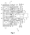
- FIG.1 A preferred embodiment of the present valve train 10 is shown in Fig.1 where a variable cam phaser 12 is mounted at a front end of a camshaft 14 of an internal combustion engine.
- the camshaft conventionally comprises a number of cams (not shown) interacting with cylinder valves (not shown) as it is well known.
- the camshaft 14, which is the driven member comprises an adapter portion 16 fixedly attached to the camshaft 14 front end e.g. by means of a screw (not shown) through bore 18 (or the adapter portion 16 could be integrally formed with the camshaft 14).
- Reference sign 20 indicates a sprocket wheel coaxial with the camshaft 14 and rotatably mounted on the camshaft adapter portion 16 by a journal bearing 19.
- the sprocket wheel 20 is, in a manner known per se, rotatably driven by the crankshaft (not shown) of the engine via a toothed drive belt or chain 22 and provides the drive torque to the cam phaser 12.
- the journal bering 19 is preferably lubricated by oil dispensed by a channel in the adapter portion 16 arriving from the camshaft, as it is kown in the art.
- the cam phaser 12 comprises an input shaft 24 rotationally coupled to the sprocket wheel 20-forming the drive member-and an output shaft 26 rotationally coupled to the camshaft 14 via its adapter portion 16.
- the cam phaser 12 actually provides a connection between the sprocket wheel 20 and camshaft 14 that enables the camshaft 14 to be relatively angularly adjusted with respect to the sprocket wheel 20 while maintaining driving engagement therebetween, as will be described below.
- the cam phaser 12 is here designed as a self-contained device with a housing 28 in which an electrical DC motor and adjusting means are accommodated.
- the electric motor comprises an outer, electromagnetic stator 30 and a magnetic rotor 32 integral with a rotor shaft 34 rotatably supported by a pair of ball bearings 36 arranged in a through-bore 38 of a partition wall 40.
- the adjusting means take the form of a planetary gearing system having a ring member 42 with internal teeth 44 that cooperates with a set of four planet gears 46 (only two of them being shown).
- the planet gears 46 are mounted on a carrier 48 and are also in meshing engagement with a sun gear 50 fixedly mounted to the rotor shaft 34.
- the ring member 42 is rotatably supported by a roller bearing 52 fixed in a shoulder section 54 in the housing 28.
- the planet gears 46 are here designed as two-stage gears, i.e.
- the planetary gears are rotatably supported by pins 62 affixed to carrier 48, itself rotatable with respect to the sun gear 50 and rotationally integral with the output shaft 26.
- the input shaft 24 and ring 42 are integrally formed and that the output shaft 26 is rotatably supported in a ball bearing 64 mounted on an inner wall of input shaft 24.
- torque transfer from the sprocket 20 to the input shaft 24 and from the output shaft 26 to the camshaft 14 is carried out by means of respective rotationally stiff, flexible couplings.
- Such couplings are here implemented as curved teeth couplings arranged as two coaxial layers.
- the input shaft 26 comprises an internally splined end portion, where the axially extending splines 66 have an inwardly curved shape over at least part of their length.
- the input shaft splined portion meshes with an externally splined ring 68 that is integral with the sprocket wheel 20.
- the output shaft 26 has an externally splined portion where the axially extending splines 70 have an outwardly curved shape over at least part of their length. These splines are in meshing engagement with and inwardly splined end portion 72 of camshaft adapter 16.
- this kind of curved teeth coupling provides a torsionally rigid coupling that however permits some degree of angular misalignment thanks to the curved teeth while the axial splines allow for some degree of axial displacement. Accordingly, an efficient and precise transmission of torque is achieved but the drive loads and vibrations from the sprocket are essentially not transmitted to the cam phaser 12. Actually, in the present configuration the chain (or belt) load is absorbed by the journal bearing 19 of the sprocket 20.
- the links between the camshaft and the sprocket wheel, respectively the camshaft are not rigid and all the components involved in the angular adjustment mechanism are situated on the cam phaser side of the flexible couplings, which only serves for torque transfer in a "soft" manner. Hence, no gearings of the cam phaser are subject to drive loads from the sprocket wheel.
- the electric motor When the engine is running and no valve timing modification is required, then the electric motor is not energized and the adjusting mechanism is simply driven along with the input shaft 24; no angular adjustment of the camshaft occurs, the sprocket 20 and the camshaft 14 rotate at the same speed.
- the electrical motor is energized in order to cause the camshaft 12 to turn at a greater or slower speed than the sprocket 20 in order to obtain the desired angular variation of the camshaft 12 corresponding to the desired valve timing.
- the sun 50 forms the planetary's input and the output is the carrier 48. Energizing the electric motor in an appropriate speed will allow rotation of the output shaft 26 at a speed greater or slower than the input shaft 24 for a time period required to bring the camshaft 12 in the desired angular position and thus provide the desired valve timing.
- the cam phaser 12 is fixed in place via a rubber block 74 that dampens vibrations and takes up misalignments and angular defaults and also blocks the housing 28 in axial direction.
- a rubber block 74 may be over-moulded around the pot-shaped housing 28.
- the cam phaser 12 is a self-contained device that can be easily mounted at a camshaft end.
- the electric motor and adjusting mechanism in completely integrated inside the housing that may thus simply be connected via its two interfaces: the input and output shaft 24 and 26, respectively.
- the configuration of the ring 42/input shaft 24 member and that of the carrier48/output shaft 26 member also closes the housing 28.
- a return spring 76 is fixed between the sprocket and the stroke limiter to ensure return of the cam phaser to a pretermined position.
- a stroke limiter of conventional design may advantageously be used to avoid excessive rotation of the camshaft 14 relative to the sprocket 20. This can be done by means of one or two pins (not shown) radially extending from the adapter portion 16 and cooperating with one or two circumferentially extending notches (not shown) in the sprocket hub, as it is known to those skilled in the art.
Landscapes
- Engineering & Computer Science (AREA)
- Mechanical Engineering (AREA)
- General Engineering & Computer Science (AREA)
- Valve Device For Special Equipments (AREA)
Abstract
A valve train for an internal combustion engine comprises a camshaft (14) and a variable cam phaser (12) connected to said camshaft (14) for driving the latter. The variable cam phaser (12) comprises: an input shaft (24) rotationally coupled to a crankshaft drive member (20); and an output shaft (26) rotationally coupled to the camshaft (14) and coaxial with the input shaft (24). Electrically operated adjusting means drivingly connect the input and output shafts (24; 26) enabling the input and output shafts (24; 26) to be selectively, angularly adjusted while maintaining driving engagement therebetween. The input and output shafts (24; 26) are coupled to the drive member (20) and camshaft (14) via respective, rotationally stiff, flexible coupling means (70, 72; 66, 68).
Description
- The present invention generally relates to the field of internal combustion engines and more specifically to a valve train with variable cam phaser for adjusting the phase of the engine camshaft.
- As it is well known, a variable cam phaser is used to change the cam lobe (valve lift event) timing to crankshaft timing while the engine is running, based on the parameters of the engine. Thereby, optimum values for fuel consumption and exhaust emissions can be obtained in different areas of the engine's operating characteristics. An elegant manner of varying the valve timing is realized by rotating the camshaft relative to its driving member, typically a sprocket wheel or pulley connected to the crankshaft via a chain, respectively a toothed belt.
- Various types of cam phasers capable of achieving this exist. Conventional cam phasers employ hydraulic actuators using high-pressure oil to enable relative angular displacement between drive and driven members. Unfortunately, hydraulic systems have difficulty operating at extremes of temperature, in particular during engine start up when the oil is cold, due to temperature related viscosity changes of the oil.
- To avoid such problems, more recent designs of cam phasers employ electric actuators in a configuration allowing their mounting at one end of the camshaft. The cam phaser typically has coaxial input and output members, the input member being coupled to the engine's sprocket wheel to act as drive member, while the output member is coupled to the camshaft. In practice, the sprocket wheel often has an extension with a toothed portion that meshes with a pinion forming the cam phaser's input member and the output member is screwed directly onto the camshaft end. An electrically actuated adjusting mechanism drivingly connects the input and output members enabling selective angular adjustment of the output shaft while maintaining driving engagement between the input and output members. The adjusting mechanism may typically comprise a gearbox arrangement in the form of a planetary gear system or a harmonic drive.
- Hence, electrically driven cam phasers comprise a relatively complex gearbox/reductor arrangement that must be manufactured with great care and precision to avoid locking and breaking of the gearings. Furthermore, the cam phaser, which is directly loaded by the sprocket wheel, is subject to important mechanical stresses and this is a cause of rapid wear and/or breaking of many cam phasers.
-
US 6,328,006 e .g. describes a cam phaser with harmonic drive.US 6,981,478 on the other hand describes a cam phaser with planetary gearing system. - Hence, there is a need for an alternative design of variable cam phaser that is less sensitive to mechanical loads from the sprocket wheel.
- This is achieved by a valve train with variable cam phaser as claimed in claim 1.
- According to the present invention, there is provided a valve train for an internal combustion engine comprising a camshaft and a variable cam phaser mounted to the camshaft for driving the latter, wherein the engine comprises a crankshaft providing a drive torque to the variable cam phaser through a drive member coaxial with the camshaft. The variable cam phaser comprises an input shaft rotationally coupled to the drive member and an output shaft rotationally coupled to the camshaft and coaxial with the input shaft. Adjusting means drivingly connect the input and output shafts and are configured to enable the input and output shafts to be selectively, angularly adjusted while maintaining driving engagement therebetween, the adjusting means comprising an electric actuator for selectively operating the angular adjustment between the input and output shafts.
- According to an important aspect of the invention, the input and output shafts are coupled to the crankshaft and camshaft via respective, rotationally stiff, flexible coupling means.
- Hence, the present invention provides a cam phaser design where conventional rigid connections at the interface between the cam phaser and the sprocket wheel and camshaft, respectively, are avoided, which reduces or avoids the transmission of mechanical shocks, tensions and loads from the crankshaft to the cam phaser. This will consequently ensure a more reliable and longer operation of the cam phaser.
- The valve train is thus advantageously designed so that all of the camphaser components are situated on the same side of the rotationally stiff, flexible coupling means, i.e. on the cam phaser side. Therefore, there is no direct, rigid connexion between the cam phaser adjustment mechanism and the sprocket wheel or the camshaft, avoiding strong mechanical tensions.
- The term flexible coupling means is conventionally used herein to designate a coupling able to transmit torque while permitting some radial and axial and angular misalignment. It is however important that the timing may not vary in an uncontrolled manner so that the flexible coupling must be rotationally stiff (i.e. the coupling is torsionally rigid and thus not flexible in the torque transmitting direction).
- Numerous designs of rotationally stiff, flexible couplings can be used for the coupling of the drive member to the input shaft and of the output shaft to the camshaft, with some adaptations if required. The design and selection of the coupling means may be made depending on the actual intensity of torque to be transmitted and on the allowable dimensions.
- In a preferred embodiment, namely for reasons of compactness, the rotationally stiff, flexible coupling means is implemented as a curved teeth coupling. Accordingly, one of the input or drive shaft may be provided at its inner or outer periphery with axially extending teeth having curved ends that engage in-between splined teeth on the outer or inner periphery of the other of the input or drive shaft. Similarly, one of the output shaft or camshaft comprises, at its inner or outer periphery, axially extending teeth having curved ends that engage in-between splined teeth on the outer or inner periphery of the other of the output shaft or camshaft. As it will be understood by those skilled in the art, such coupling allows for a torsionally rigid torque transmitting coupling that permits some degree of misalignment or end movement (i.e. some radial/angular and axial displacement).
- But other types of rotationally stiff, flexible couplings may alternatively be used such as, but not exclusively, for example: Oldham couplings, universal joints, etc.
- Regarding the adjusting means, here also a variety of designs are possible, although harmonic drives or epicyclic/planetary gearing systems are common for this function. For example, adjusting means may comprise a planetary gearing system having a ring gear coupled to the input shaft, a sun gear rotatable by an electric motor and planet gears supported by a carrier coupled to the output shaft. As it will be clear to those skilled in the art, other configurations of planetary gearing systems are also possible.
- Preferably, the camshaft comprises an adapter portion at a front end thereof, to which said cam phaser output shaft is coupled.
- The cam phaser is advantageously arranged in a housing so that it can be handled as a self-contained device simply having a pair of coaxial input and output shaft interfacing with the sprocket and camshaft. Preferably the cam phaser is fixed by means of an annular rubber block surrounding its housing. Such rubber block absorbs small dimensional variations (e.g. missconcentricity and miss-alignment) and permits an axial locking of the cam phaser, in particular when using a curved teeth coupling.
- A return spring system may be associated with the cam phaser to ensure return of the cam phaser to a pretermined position.
- Also, a stroke limiter system may be associated with the cam phaser to avoid excessive angular modification of the camshaft and thus of the valve timing. Various designs of stroke limiter are known in the art and can be easily adapted to operate with the present camshaft.
- In addition, the present cam phaser may include a phase detector to determine the angular position of the camshaft as well as an electronic control unit to operate the electric actuator in accordance with phase information provided by an engine control unit based on engine parameters.
- The present invention also concerns an internal combustion engine equipped with the present valve train.
- The present invention will now be described, by way of example, with reference to the accompanying drawings, in which:
- FIG. 1: is
- a section view through a preferred embodiment of the cam phaser attached to a camshaft end in a valve train according to the inven- tion; and
- FIG. 2: is
- a schematic exploded view -also axially cut- of the couplings between drive member/input shaft and output shaft/cam shaft adapter.
- A preferred embodiment of the
present valve train 10 is shown inFig.1 where avariable cam phaser 12 is mounted at a front end of acamshaft 14 of an internal combustion engine. In such valve train, the camshaft conventionally comprises a number of cams (not shown) interacting with cylinder valves (not shown) as it is well known. Conventionally, thecamshaft 14, which is the driven member, comprises anadapter portion 16 fixedly attached to thecamshaft 14 front end e.g. by means of a screw (not shown) through bore 18 (or theadapter portion 16 could be integrally formed with the camshaft 14).Reference sign 20 indicates a sprocket wheel coaxial with thecamshaft 14 and rotatably mounted on thecamshaft adapter portion 16 by a journal bearing 19. Thesprocket wheel 20 is, in a manner known per se, rotatably driven by the crankshaft (not shown) of the engine via a toothed drive belt orchain 22 and provides the drive torque to thecam phaser 12. Thejournal bering 19 is preferably lubricated by oil dispensed by a channel in theadapter portion 16 arriving from the camshaft, as it is kown in the art. - The
cam phaser 12 comprises aninput shaft 24 rotationally coupled to the sprocket wheel 20-forming the drive member-and anoutput shaft 26 rotationally coupled to thecamshaft 14 via itsadapter portion 16. Thecam phaser 12 actually provides a connection between thesprocket wheel 20 andcamshaft 14 that enables thecamshaft 14 to be relatively angularly adjusted with respect to thesprocket wheel 20 while maintaining driving engagement therebetween, as will be described below. - Referring more specifically to the structure of the
cam phaser 12, it is here designed as a self-contained device with ahousing 28 in which an electrical DC motor and adjusting means are accommodated. The electric motor comprises an outer,electromagnetic stator 30 and amagnetic rotor 32 integral with arotor shaft 34 rotatably supported by a pair ofball bearings 36 arranged in a through-bore 38 of apartition wall 40. - In the present variant, the adjusting means take the form of a planetary gearing system having a
ring member 42 withinternal teeth 44 that cooperates with a set of four planet gears 46 (only two of them being shown). The planet gears 46 are mounted on acarrier 48 and are also in meshing engagement with asun gear 50 fixedly mounted to therotor shaft 34. As can be seen fromFig.1 , thering member 42 is rotatably supported by aroller bearing 52 fixed in ashoulder section 54 in thehousing 28. The planet gears 46 are here designed as two-stage gears, i.e. they have a firstexternal toothing 56 meshing with thetheeth 44 ofinternal ring 42 and a secondouter toothing 58 meshing with theexternal toothing 60 of thesun gear 50. The planetary gears are rotatably supported bypins 62 affixed tocarrier 48, itself rotatable with respect to thesun gear 50 and rotationally integral with theoutput shaft 26. - It may be still be noted that the
input shaft 24 andring 42 are integrally formed and that theoutput shaft 26 is rotatably supported in aball bearing 64 mounted on an inner wall ofinput shaft 24. - It is to be appreciated that torque transfer from the
sprocket 20 to theinput shaft 24 and from theoutput shaft 26 to thecamshaft 14 is carried out by means of respective rotationally stiff, flexible couplings. Such couplings are here implemented as curved teeth couplings arranged as two coaxial layers. - As best seen in
Fig.2 , theinput shaft 26 comprises an internally splined end portion, where theaxially extending splines 66 have an inwardly curved shape over at least part of their length. The input shaft splined portion meshes with an externallysplined ring 68 that is integral with thesprocket wheel 20. Similarly, theoutput shaft 26 has an externally splined portion where theaxially extending splines 70 have an outwardly curved shape over at least part of their length. These splines are in meshing engagement with and inwardlysplined end portion 72 ofcamshaft adapter 16. - As it will be understood, this kind of curved teeth coupling provides a torsionally rigid coupling that however permits some degree of angular misalignment thanks to the curved teeth while the axial splines allow for some degree of axial displacement. Accordingly, an efficient and precise transmission of torque is achieved but the drive loads and vibrations from the sprocket are essentially not transmitted to the
cam phaser 12. Actually, in the present configuration the chain (or belt) load is absorbed by the journal bearing 19 of thesprocket 20. - Hence, the links between the camshaft and the sprocket wheel, respectively the camshaft, are not rigid and all the components involved in the angular adjustment mechanism are situated on the cam phaser side of the flexible couplings, which only serves for torque transfer in a "soft" manner. Hence, no gearings of the cam phaser are subject to drive loads from the sprocket wheel.
- When the engine is running and no valve timing modification is required, then the electric motor is not energized and the adjusting mechanism is simply driven along with the
input shaft 24; no angular adjustment of the camshaft occurs, thesprocket 20 and thecamshaft 14 rotate at the same speed. To perform a variation of valve timing, the electrical motor is energized in order to cause thecamshaft 12 to turn at a greater or slower speed than thesprocket 20 in order to obtain the desired angular variation of thecamshaft 12 corresponding to the desired valve timing. Considering the present configuration of the planetary gearing, thesun 50 forms the planetary's input and the output is thecarrier 48. Energizing the electric motor in an appropriate speed will allow rotation of theoutput shaft 26 at a speed greater or slower than theinput shaft 24 for a time period required to bring thecamshaft 12 in the desired angular position and thus provide the desired valve timing. - Preferably, when using such axial splines, the
cam phaser 12 is fixed in place via arubber block 74 that dampens vibrations and takes up misalignments and angular defaults and also blocks thehousing 28 in axial direction.Such rubber block 74 may be over-moulded around the pot-shapedhousing 28. - As already mentioned, the
cam phaser 12 is a self-contained device that can be easily mounted at a camshaft end. The electric motor and adjusting mechanism in completely integrated inside the housing that may thus simply be connected via its two interfaces: the input andoutput shaft ring 42/input shaft 24 member and that of the carrier48/output shaft 26 member also closes thehousing 28. - Preferably, a
return spring 76 is fixed between the sprocket and the stroke limiter to ensure return of the cam phaser to a pretermined position. - Also, a stroke limiter of conventional design may advantageously be used to avoid excessive rotation of the
camshaft 14 relative to thesprocket 20. This can be done by means of one or two pins (not shown) radially extending from theadapter portion 16 and cooperating with one or two circumferentially extending notches (not shown) in the sprocket hub, as it is known to those skilled in the art.
Claims (11)
- A valve train for an internal combustion engine comprising a camshaft (14) and a variable cam phaser (12) connected to said camshaft (14) for driving the latter, said engine comprising a crankshaft providing a drive torque for said variable cam phaser (12) through a drive member (20) coaxial with said camshaft (14), wherein said variable cam phaser (12) comprises:an input shaft (24) rotationally coupled to said drive member (20);an output shaft (26) rotationally coupled to said camshaft (14) and coaxial with said input shaft (24);adjusting means drivingly connecting said input and output shafts (24; 26) enabling said input and output shafts (24; 26) to be selectively, angularly adjusted while maintaining driving engagement therebetween, wherein the adjusting means comprise an electric actuator for selectively operating an angular adjustment;characterized in that said input and output shafts (24; 26) are coupled to said drive member (20) and camshaft (14) via respective, rotationally stiff,flexible coupling means.
- The valve train according to claim 1, wherein the rotationally stiff, flexible coupling between said input shaft and drive member and/or the coupling between said output shaft and camshaft is implemented as curved teeth coupling (70, 72; 66, 68).
- The valve train according to claim 2, wherein one of said input or drive shaft is provided at its inner or outer periphery with axially extending teeth (66) having curved ends that engage in-between splined teeth (68) on the outer or inner periphery of the other of the input or drive shaft; and one of said output shaft or camshaft comprises, at its inner or outer periphery, axially extending teeth having curved ends (70) that engage in-between splined teeth (72) on the outer or inner periphery of the other of said output shaft or camshaft.
- The valve train according to claim 1, 2 or 3, wherein said adjusting means comprise a harmonic drive or planetary gearing system.
- The valve train according to claim 4, wherein said adjusting means comprise a planetary gearing system having a ring gear (42) coupled to said input shaft (24), a sun gear (50) rotatable by an electric motor and planet gears (46) supported by a carrier (48) coupled to said output shaft (26).
- The valve train according to any one of the preceding claims, wherein said camshaft (14) comprises an adapter portion (16) at a front end thereof, to which said cam phaser output shaft (26) is coupled.
- The valve train according to any one of the preceding claims, wherein said cam phaser (12) is arranged in a housing (28).
- The valve train according to claim 7, wherein said cam phaser (12) is fixed by means of an annular rubber block (74) surrounding its housing.
- The valve train according to any one of the preceding claims, comprising a return spring associated with said cam phaser.
- The valve train according to any one of the preceding claims, comprising a stroke limiter system associated with said cam phaser.
- An internal combustion engine comprising a valve train according to any one of the preceding claims.
Priority Applications (6)
| Application Number | Priority Date | Filing Date | Title |
|---|---|---|---|
| EP20090169090 EP2295741A1 (en) | 2009-08-31 | 2009-08-31 | Valve train with variable cam phaser |
| PCT/EP2010/061549 WO2011023525A1 (en) | 2009-08-31 | 2010-08-09 | Valve train with variable cam phaser |
| EP10751829.2A EP2473717B1 (en) | 2009-08-31 | 2010-08-09 | Valve train with variable cam phaser |
| CN201080038248.7A CN102482959B (en) | 2009-08-31 | 2010-08-09 | Valve device with variable cam phaser |
| JP2012525975A JP5615923B2 (en) | 2009-08-31 | 2010-08-09 | Valve actuator with variable cam phaser |
| US13/392,985 US8584636B2 (en) | 2009-08-31 | 2010-08-09 | Valve train with variable cam phaser |
Applications Claiming Priority (1)
| Application Number | Priority Date | Filing Date | Title |
|---|---|---|---|
| EP20090169090 EP2295741A1 (en) | 2009-08-31 | 2009-08-31 | Valve train with variable cam phaser |
Publications (1)
| Publication Number | Publication Date |
|---|---|
| EP2295741A1 true EP2295741A1 (en) | 2011-03-16 |
Family
ID=41571819
Family Applications (2)
| Application Number | Title | Priority Date | Filing Date |
|---|---|---|---|
| EP20090169090 Withdrawn EP2295741A1 (en) | 2009-08-31 | 2009-08-31 | Valve train with variable cam phaser |
| EP10751829.2A Not-in-force EP2473717B1 (en) | 2009-08-31 | 2010-08-09 | Valve train with variable cam phaser |
Family Applications After (1)
| Application Number | Title | Priority Date | Filing Date |
|---|---|---|---|
| EP10751829.2A Not-in-force EP2473717B1 (en) | 2009-08-31 | 2010-08-09 | Valve train with variable cam phaser |
Country Status (5)
| Country | Link |
|---|---|
| US (1) | US8584636B2 (en) |
| EP (2) | EP2295741A1 (en) |
| JP (1) | JP5615923B2 (en) |
| CN (1) | CN102482959B (en) |
| WO (1) | WO2011023525A1 (en) |
Cited By (2)
| Publication number | Priority date | Publication date | Assignee | Title |
|---|---|---|---|---|
| WO2013060531A1 (en) * | 2011-10-27 | 2013-05-02 | Magna Powertrain Ag & Co Kg | Camshaft adjusting means |
| WO2014092963A1 (en) * | 2012-12-10 | 2014-06-19 | Borgwarner Inc. | Split ring gear planetary cam phaser |
Families Citing this family (19)
| Publication number | Priority date | Publication date | Assignee | Title |
|---|---|---|---|---|
| JP5208154B2 (en) * | 2010-04-20 | 2013-06-12 | 日立オートモティブシステムズ株式会社 | Valve timing control device for internal combustion engine |
| US9297281B2 (en) * | 2010-04-23 | 2016-03-29 | Borgwarner, Inc. | Concentric camshaft phaser flex plate |
| US8622037B2 (en) * | 2010-05-12 | 2014-01-07 | Delphi Technologies, Inc. | Harmonic drive camshaft phaser with a compact drive sprocket |
| US8677961B2 (en) * | 2011-07-18 | 2014-03-25 | Delphi Technologies, Inc. | Harmonic drive camshaft phaser with lock pin for selectivley preventing a change in phase relationship |
| US9228455B1 (en) | 2013-03-14 | 2016-01-05 | Brunswick Corporation | Outboard motors and marine engines having cam phaser arrangements |
| US9664073B2 (en) * | 2014-02-25 | 2017-05-30 | Delphi Technologies, Inc. | Modular electrically actuated camshaft phaser |
| DE112015002518B4 (en) | 2014-06-25 | 2017-11-16 | Borgwarner Inc. | Camshaft adjuster systems and associated adjuster with lock |
| JP5987868B2 (en) * | 2014-07-22 | 2016-09-07 | 株式会社デンソー | Valve timing adjustment device |
| CN106605044B (en) * | 2014-09-04 | 2018-02-23 | 博格华纳公司 | Engine variable camshaft timing phaser with planetary gearsets |
| DE102016100819A1 (en) * | 2015-02-20 | 2016-08-25 | Abb Turbo Systems Ag | coupling device |
| US10072537B2 (en) * | 2015-07-23 | 2018-09-11 | Husco Automotive Holdings Llc | Mechanical cam phasing system and methods |
| SE541810C2 (en) * | 2016-05-24 | 2019-12-17 | Scania Cv Ab | Variable cam timing phaser having two central control valves |
| SE539979C2 (en) | 2016-06-08 | 2018-02-20 | Scania Cv Ab | Rotational hydraulic logic device and variable cam timing phaser utilizing such a device |
| SE539980C2 (en) | 2016-06-08 | 2018-02-20 | Scania Cv Ab | Variable cam timing phaser utilizing series-coupled check valves |
| CN108331632B (en) * | 2017-01-20 | 2021-12-28 | 胡斯可汽车控股有限公司 | Cam phasing systems and methods |
| JP2019027435A (en) | 2017-07-31 | 2019-02-21 | ボーグワーナー インコーポレーテッド | e-Phaser cushion stop |
| US20190040768A1 (en) * | 2017-08-01 | 2019-02-07 | GM Global Technology Operations LLC | Camshaft assembly |
| WO2019212555A1 (en) * | 2018-05-03 | 2019-11-07 | Borgwarner Inc. | Electrically actuated camshaft phaser fluid escapement channel |
| WO2023055475A2 (en) | 2021-07-30 | 2023-04-06 | Board Of Trustees Of Michigan State University | Actuation system for an internal combustion engine |
Citations (8)
| Publication number | Priority date | Publication date | Assignee | Title |
|---|---|---|---|---|
| US5474499A (en) * | 1993-07-12 | 1995-12-12 | The United States Of America As Represented By The Secretary Of The Navy | Flexible drive shaft coupling |
| GB2354553A (en) * | 1999-09-23 | 2001-03-28 | Turbo Genset Company Ltd The | Electric motor driven turbocharger. |
| US6328006B1 (en) | 1999-03-23 | 2001-12-11 | Tcg Unitech Aktiengesellschaft | Device for adjusting the phase angle of a camshaft of an internal combustion engine |
| US20030226532A1 (en) * | 2002-04-19 | 2003-12-11 | Nippon Soken, Inc. | Valve timing adjusting device |
| US6981478B2 (en) | 2002-10-17 | 2006-01-03 | Ina-Schaeffler Kg | Electrically driven camshaft adjuster |
| EP1715143A2 (en) * | 2005-04-23 | 2006-10-25 | Schaeffler KG | Camshaft phasing device for an internal combustion engine |
| US20070169731A1 (en) * | 2006-01-26 | 2007-07-26 | Farah Philippe S | Variable cam phaser apparatus |
| DE102007000809A1 (en) * | 2006-10-06 | 2008-04-10 | Denso Corp., Kariya | valve timing |
Family Cites Families (10)
| Publication number | Priority date | Publication date | Assignee | Title |
|---|---|---|---|---|
| JPH07197820A (en) * | 1993-12-28 | 1995-08-01 | Kanesaka Gijutsu Kenkyusho:Kk | Miller cycle engine |
| US6216654B1 (en) * | 1999-08-27 | 2001-04-17 | Daimlerchrysler Corporation | Phase changing device |
| JP2002013597A (en) * | 2000-06-29 | 2002-01-18 | Toyoda Mach Works Ltd | Worm gear unit and electrically operated power steering apparatus |
| DE10248351A1 (en) * | 2002-10-17 | 2004-04-29 | Ina-Schaeffler Kg | Electrically driven camshaft adjuster |
| JP2006242243A (en) * | 2005-03-02 | 2006-09-14 | Nissan Motor Co Ltd | Connection structure of automatic transmission and engine |
| US7421990B2 (en) * | 2006-08-22 | 2008-09-09 | Delphi Technologies, Inc. | Harmonic drive camshaft phaser |
| JP2007231956A (en) * | 2007-06-06 | 2007-09-13 | Denso Corp | Valve operation timing control device |
| JP2009013801A (en) * | 2007-07-02 | 2009-01-22 | Kawasaki Heavy Ind Ltd | Motorcycle with valve mechanism |
| JP4992757B2 (en) * | 2008-02-26 | 2012-08-08 | マツダ株式会社 | Control method for internal combustion engine |
| JP5102071B2 (en) * | 2008-03-03 | 2012-12-19 | 日鍛バルブ株式会社 | Phase variable device for automobile engine |
-
2009
- 2009-08-31 EP EP20090169090 patent/EP2295741A1/en not_active Withdrawn
-
2010
- 2010-08-09 EP EP10751829.2A patent/EP2473717B1/en not_active Not-in-force
- 2010-08-09 CN CN201080038248.7A patent/CN102482959B/en not_active Expired - Fee Related
- 2010-08-09 US US13/392,985 patent/US8584636B2/en not_active Expired - Fee Related
- 2010-08-09 JP JP2012525975A patent/JP5615923B2/en not_active Expired - Fee Related
- 2010-08-09 WO PCT/EP2010/061549 patent/WO2011023525A1/en not_active Ceased
Patent Citations (8)
| Publication number | Priority date | Publication date | Assignee | Title |
|---|---|---|---|---|
| US5474499A (en) * | 1993-07-12 | 1995-12-12 | The United States Of America As Represented By The Secretary Of The Navy | Flexible drive shaft coupling |
| US6328006B1 (en) | 1999-03-23 | 2001-12-11 | Tcg Unitech Aktiengesellschaft | Device for adjusting the phase angle of a camshaft of an internal combustion engine |
| GB2354553A (en) * | 1999-09-23 | 2001-03-28 | Turbo Genset Company Ltd The | Electric motor driven turbocharger. |
| US20030226532A1 (en) * | 2002-04-19 | 2003-12-11 | Nippon Soken, Inc. | Valve timing adjusting device |
| US6981478B2 (en) | 2002-10-17 | 2006-01-03 | Ina-Schaeffler Kg | Electrically driven camshaft adjuster |
| EP1715143A2 (en) * | 2005-04-23 | 2006-10-25 | Schaeffler KG | Camshaft phasing device for an internal combustion engine |
| US20070169731A1 (en) * | 2006-01-26 | 2007-07-26 | Farah Philippe S | Variable cam phaser apparatus |
| DE102007000809A1 (en) * | 2006-10-06 | 2008-04-10 | Denso Corp., Kariya | valve timing |
Cited By (2)
| Publication number | Priority date | Publication date | Assignee | Title |
|---|---|---|---|---|
| WO2013060531A1 (en) * | 2011-10-27 | 2013-05-02 | Magna Powertrain Ag & Co Kg | Camshaft adjusting means |
| WO2014092963A1 (en) * | 2012-12-10 | 2014-06-19 | Borgwarner Inc. | Split ring gear planetary cam phaser |
Also Published As
| Publication number | Publication date |
|---|---|
| US8584636B2 (en) | 2013-11-19 |
| CN102482959A (en) | 2012-05-30 |
| US20120186548A1 (en) | 2012-07-26 |
| CN102482959B (en) | 2014-02-12 |
| EP2473717B1 (en) | 2013-10-16 |
| WO2011023525A1 (en) | 2011-03-03 |
| JP2013503287A (en) | 2013-01-31 |
| EP2473717A1 (en) | 2012-07-11 |
| JP5615923B2 (en) | 2014-10-29 |
Similar Documents
| Publication | Publication Date | Title |
|---|---|---|
| EP2473717B1 (en) | Valve train with variable cam phaser | |
| EP2386732B1 (en) | Harmonic drive camshaft phaser with a compact drive sprocket | |
| US8800513B2 (en) | Axially compact coupling for a camshaft phaser actuated by electric motor | |
| US9534513B2 (en) | Camshaft phaser actuated by an electric motor | |
| CN103429856B (en) | Concentric camshaft phaser torsional drive mechanism | |
| JP4735720B2 (en) | Valve timing adjustment device | |
| US8322318B2 (en) | Harmonic drive camshaft phaser with phase authority stops | |
| JP2563116B2 (en) | Adjustment device for adjusting the control time of the valve | |
| US9297283B2 (en) | Camshaft unit | |
| US10808580B2 (en) | Electrically-actuated VCT lock | |
| JP2016061234A (en) | Valve timing control device | |
| US11459916B2 (en) | Valve timing adjustment device | |
| JP5240309B2 (en) | Valve timing adjustment device | |
| JPH05263614A (en) | Valve timing adjustor for internal combustion engine | |
| EP1801367A1 (en) | Variable cam phaser apparatus | |
| US7341030B2 (en) | Valve timing controller | |
| CN103277162B (en) | For establishing the valve device of the coupling device effectively connected, the method for running the coupling device and internal combustion engine | |
| CN117967421B (en) | Torque limiting torsion joint | |
| JP2009036174A (en) | Fuel pump drive device for internal combustion engine | |
| JPH07224619A (en) | Valve timing control device for DOHC internal combustion engine | |
| GB2469881A (en) | Mechanism for varying the phase angle between an input shaft and an output shaft, eg in i.c. engine valve gear | |
| JPH1082307A (en) | Engine valve gear |
Legal Events
| Date | Code | Title | Description |
|---|---|---|---|
| PUAI | Public reference made under article 153(3) epc to a published international application that has entered the european phase |
Free format text: ORIGINAL CODE: 0009012 |
|
| AK | Designated contracting states |
Kind code of ref document: A1 Designated state(s): AT BE BG CH CY CZ DE DK EE ES FI FR GB GR HR HU IE IS IT LI LT LU LV MC MK MT NL NO PL PT RO SE SI SK SM TR |
|
| AX | Request for extension of the european patent |
Extension state: AL BA RS |
|
| STAA | Information on the status of an ep patent application or granted ep patent |
Free format text: STATUS: THE APPLICATION IS DEEMED TO BE WITHDRAWN |
|
| 18D | Application deemed to be withdrawn |
Effective date: 20110917 |