EP2295737A2 - Hydraulische Einstellvorrichtung zum Schließen eines Ansaugventils - Google Patents
Hydraulische Einstellvorrichtung zum Schließen eines Ansaugventils Download PDFInfo
- Publication number
- EP2295737A2 EP2295737A2 EP10008441A EP10008441A EP2295737A2 EP 2295737 A2 EP2295737 A2 EP 2295737A2 EP 10008441 A EP10008441 A EP 10008441A EP 10008441 A EP10008441 A EP 10008441A EP 2295737 A2 EP2295737 A2 EP 2295737A2
- Authority
- EP
- European Patent Office
- Prior art keywords
- valve
- snubber
- chamber
- actuator
- snubbing element
- Prior art date
- Legal status (The legal status is an assumption and is not a legal conclusion. Google has not performed a legal analysis and makes no representation as to the accuracy of the status listed.)
- Granted
Links
- 230000007246 mechanism Effects 0.000 claims abstract description 55
- 239000012530 fluid Substances 0.000 claims description 77
- 238000002485 combustion reaction Methods 0.000 claims description 30
- 238000004891 communication Methods 0.000 claims description 18
- 230000003993 interaction Effects 0.000 claims description 12
- 238000000034 method Methods 0.000 claims description 12
- 239000000446 fuel Substances 0.000 claims description 8
- 230000009471 action Effects 0.000 claims description 3
- 230000007423 decrease Effects 0.000 claims description 2
- 230000005611 electricity Effects 0.000 claims 2
- 238000010586 diagram Methods 0.000 description 4
- 230000008569 process Effects 0.000 description 4
- 238000010926 purge Methods 0.000 description 4
- 230000000694 effects Effects 0.000 description 3
- 239000007789 gas Substances 0.000 description 3
- 238000001816 cooling Methods 0.000 description 2
- 238000006073 displacement reaction Methods 0.000 description 2
- 238000010304 firing Methods 0.000 description 2
- 230000004044 response Effects 0.000 description 2
- 230000015572 biosynthetic process Effects 0.000 description 1
- 239000003054 catalyst Substances 0.000 description 1
- 238000010531 catalytic reduction reaction Methods 0.000 description 1
- 230000006835 compression Effects 0.000 description 1
- 238000007906 compression Methods 0.000 description 1
- 238000011217 control strategy Methods 0.000 description 1
- 239000002283 diesel fuel Substances 0.000 description 1
- 238000005516 engineering process Methods 0.000 description 1
- 238000002347 injection Methods 0.000 description 1
- 239000007924 injection Substances 0.000 description 1
Images




Classifications
-
- F—MECHANICAL ENGINEERING; LIGHTING; HEATING; WEAPONS; BLASTING
- F01—MACHINES OR ENGINES IN GENERAL; ENGINE PLANTS IN GENERAL; STEAM ENGINES
- F01L—CYCLICALLY OPERATING VALVES FOR MACHINES OR ENGINES
- F01L13/00—Modifications of valve-gear to facilitate reversing, braking, starting, changing compression ratio, or other specific operations
- F01L13/0015—Modifications of valve-gear to facilitate reversing, braking, starting, changing compression ratio, or other specific operations for optimising engine performances by modifying valve lift according to various working parameters, e.g. rotational speed, load, torque
- F01L13/0021—Modifications of valve-gear to facilitate reversing, braking, starting, changing compression ratio, or other specific operations for optimising engine performances by modifying valve lift according to various working parameters, e.g. rotational speed, load, torque by modification of rocker arm ratio
-
- F—MECHANICAL ENGINEERING; LIGHTING; HEATING; WEAPONS; BLASTING
- F01—MACHINES OR ENGINES IN GENERAL; ENGINE PLANTS IN GENERAL; STEAM ENGINES
- F01L—CYCLICALLY OPERATING VALVES FOR MACHINES OR ENGINES
- F01L13/00—Modifications of valve-gear to facilitate reversing, braking, starting, changing compression ratio, or other specific operations
-
- F—MECHANICAL ENGINEERING; LIGHTING; HEATING; WEAPONS; BLASTING
- F01—MACHINES OR ENGINES IN GENERAL; ENGINE PLANTS IN GENERAL; STEAM ENGINES
- F01L—CYCLICALLY OPERATING VALVES FOR MACHINES OR ENGINES
- F01L1/00—Valve-gear or valve arrangements, e.g. lift-valve gear
- F01L1/12—Transmitting gear between valve drive and valve
- F01L1/14—Tappets; Push rods
- F01L1/16—Silencing impact; Reducing wear
-
- F—MECHANICAL ENGINEERING; LIGHTING; HEATING; WEAPONS; BLASTING
- F01—MACHINES OR ENGINES IN GENERAL; ENGINE PLANTS IN GENERAL; STEAM ENGINES
- F01L—CYCLICALLY OPERATING VALVES FOR MACHINES OR ENGINES
- F01L1/00—Valve-gear or valve arrangements, e.g. lift-valve gear
- F01L1/34—Valve-gear or valve arrangements, e.g. lift-valve gear characterised by the provision of means for changing the timing of the valves without changing the duration of opening and without affecting the magnitude of the valve lift
- F01L1/344—Valve-gear or valve arrangements, e.g. lift-valve gear characterised by the provision of means for changing the timing of the valves without changing the duration of opening and without affecting the magnitude of the valve lift changing the angular relationship between crankshaft and camshaft, e.g. using helicoidal gear
- F01L1/3442—Valve-gear or valve arrangements, e.g. lift-valve gear characterised by the provision of means for changing the timing of the valves without changing the duration of opening and without affecting the magnitude of the valve lift changing the angular relationship between crankshaft and camshaft, e.g. using helicoidal gear using hydraulic chambers with variable volume to transmit the rotating force
- F01L2001/34423—Details relating to the hydraulic feeding circuit
- F01L2001/34446—Fluid accumulators for the feeding circuit
-
- F—MECHANICAL ENGINEERING; LIGHTING; HEATING; WEAPONS; BLASTING
- F01—MACHINES OR ENGINES IN GENERAL; ENGINE PLANTS IN GENERAL; STEAM ENGINES
- F01L—CYCLICALLY OPERATING VALVES FOR MACHINES OR ENGINES
- F01L2800/00—Methods of operation using a variable valve timing mechanism
- F01L2800/10—Providing exhaust gas recirculation [EGR]
Definitions
- This disclosure relates to internal combustion engines, and in particular it relates to a mechanism for controlling timing of engine cylinder valve operation, especially timing of cylinder intake valve closing.
- Control of combustion phasing in an internal combustion engine is useful when applied to EGR (exhaust gas recirculation), fuel injection timing, and cylinder cooling strategies. Poor calibration however may at times cause undesired engine operation, such as misfire in ranges where EGR rates are high. Non-uniform EGR distribution or in-cylinder cooling can also lead to cylinder-to-cylinder variability of combustion phasing.
- EGR exhaust gas recirculation
- fuel injection timing fuel injection timing
- cylinder cooling strategies Poor calibration however may at times cause undesired engine operation, such as misfire in ranges where EGR rates are high.
- Non-uniform EGR distribution or in-cylinder cooling can also lead to cylinder-to-cylinder variability of combustion phasing.
- control of intake valve closing (IVC) on an individual engine cylinder basis can provide better overall control of a multi-cylinder diesel engine. Control can be further improved in the presence of a combustion phasing feedback, such as cylinder pressure or ion sensing technology.
- This disclosure relates to a mechanism that can be applied to an individual engine cylinder to provide variable valve actuation (WA), especially variable closing of an intake valve for an individual engine cylinder to effectively control the cylinder compression ratio.
- WA variable valve actuation
- the disclosed mechanism can limit NOx in engine exhaust without having to de-rate an engine to a level would that would limit NOx without having to use an expensive exhaust after-treatment system containing a lean NOx trap (LNT) or an SCR (selective catalytic reduction) catalyst.
- LNT lean NOx trap
- SCR selective catalytic reduction
- a general aspect of the disclosure relates to an internal combustion engine comprising an intake system through which air enters at least one engine cylinder within which the air supports combustion of fuel to operate the engine and an exhaust system through which products of in-cylinder combustion are exhausted. Cylinder valves control communication of the respective systems with the at least one cylinder.
- One of the cylinder valves is biased closed by a valve spring to seat on a valve seat but is increasingly opened by a rocker of a valve opening mechanism pivoting about a relocatable axis and increasingly compressing the valve spring as the one valve increasingly opens.
- a hydraulic actuator hydraulically locks the relocatable axis against relocation as the one valve is being increasingly opened by the rocker, and with the one valve open, unlocks the relocatable axis to allow the valve spring to increasingly expand and simultaneously force the one valve toward the valve seat and the relocatable axis to relocate.
- a hydraulic fluid pressure source delivers hydraulic fluid through a first check valve to a variable volume chamber of a hydraulic snubber that is disposed to snub motion of the one valve toward the valve seat, through a second check valve to a variable volume chamber of the actuator, and to a hydraulic accumulator that is in fluid communication with the snubber chamber and a first port of a control valve that has a second port in fluid communication with the actuator chamber.
- variable volume chamber of the snubber is cooperatively defined by a snubbing element and by a body with respect to which the snubbing element is extendable and retractable.
- the snubbing element and the snubber body collectively comprise a variable restriction through which the variable volume chamber of the snubber is in fluid communication with the accumulator, the hydraulic fluid pressure source, and the first port of the control valve, and which decreases and increases respectively as the snubbing element extends and retracts respectively relative to the snubber body.
- the hydraulic fluid pressure source and accumulator collectively are effective, as the valve opening mechanism is increasingly opening the one valve, to force hydraulic fluid through the first check valve into the snubber chamber and thereby extend the snubbing element relative to the snubber body.
- the control valve closes the first port to the second port to hydraulically lock the actuator by preventing hydraulic fluid that had been forced into the actuator chamber before the one valve was unseated from the valve seat from escaping from the actuator chamber.
- the control valve opens the first port to the second port to unlock the actuator by communicating the actuator chamber to the accumulator and consequently allow the valve spring to force hydraulic fluid out of the actuator chamber into the accumulator as the one valve is being forced toward the seat by the valve spring and snubbed by interaction with the snubber that forces the snubbing element to retract and force fluid out of the snubber chamber into the accumulator with increasing restriction as the one valve moves toward the seat.
- Another general aspect of this disclosure relates to a mechanism for association with an engine cylinder valve that is biased closed on a valve seat by a valve spring and opened by a valve rocker of a valve opening mechanism for endowing the cylinder valve with the capability of being operated from open to closed at various times during engine cycles.
- the mechanism comprises a hydraulic actuator comprising a variable volume chamber and a control valve controlling the hydraulic actuator a) to constrain a pivot axis of the valve rocker against relocation while the valve opening mechanism is operating the valve rocker to force the cylinder valve increasingly open and increasingly compressing the valve spring, and b) to release the constraint after the cylinder valve has been forced open for enabling the pivot axis to relocate as the valve spring increasingly extends to move the cylinder valve toward closing on the valve seat.
- a first check valve allows hydraulic fluid from a hydraulic fluid pressure source and a hydraulic accumulator that is in fluid communication with the source to be introduced to expand the volume of the chamber and disallow back-flow of fluid from the chamber.
- a hydraulic snubber comprising a variable volume chamber snubs motion of the cylinder valve toward closing on the valve seat.
- a second check valve allows hydraulic fluid from the hydraulic fluid pressure source to expand the volume of the snubber chamber and disallow back-flow of fluid from the snubber chamber.
- variable volume chamber of the snubber is cooperatively defined by a snubbing element and by a body with respect to which the snubbing element is extended by hydraulic fluid introduced into the snubber chamber through the second check valve.
- the snubbing element and the snubber body cooperatively comprise a variable restriction through which the snubber chamber communicates with the accumulator and which varies as the snubbing element retracts relative to the snubber body.
- the control valve provides the functions of causing the actuator to constrain the axis against relocation by closing the actuator chamber to the accumulator and of causing the actuator to release the constraint by opening the actuator chamber to the accumulator and consequently enable the valve spring to act via the rocker to force fluid out of the actuator chamber into the accumulator, and via cylinder valve interaction with the snubbing element, to force fluid out of the snubber chamber and into the accumulator with increasing restriction of fluid flow by the variable restriction as the snubbing element is increasingly retracted.
- the disclosure also relates to a method of operating an engine cylinder valve that is biased closed on a valve seat by a valve spring, that is opened by pivoting of a valve rocker of a valve opening mechanism about a relocatable axis during an engine cycle, and whose closing motion toward the valve seat is snubbed by a hydraulic snubber.
- the method comprises communicating a variable volume chamber of the snubber through a first check valve to a hydraulic fluid pressure source to allow fluid to flow into the snubber chamber and disallow backflow from the snubber chamber, communicating a variable volume chamber of a hydraulic actuator through a second check valve to a hydraulic accumulator that is in fluid communication with the hydraulic fluid pressure source to allow fluid to flow into the actuator chamber and disallow backflow from the actuator chamber, communicating the actuator chamber through a control valve to the source, the accumulator, and the snubber, selectively operating the control valve a) to constrain the relocatable axis of the valve rocker against relocation by closing the actuator chamber to the accumulator, the source, and the snubber chamber as the valve opening mechanism is operating the valve rocker to force the cylinder valve increasingly open and increasingly compress the valve spring, thereby hydraulically locking the actuator during cylinder valve opening, and b) after the cylinder valve has been forced open, to release the constraint by opening the actuator chamber to the accumulator,
- Another aspect of the disclosure relates to a hydraulic snubber for snubbing closing motion of an engine cylinder valve on a seat.
- the snubber comprises a variable volume chamber cooperatively defined by a snubbing element and by a body with respect to which the snubbing element is linearly displaceable, a source port through which hydraulic fluid from a hydraulic fluid pressure source can be delivered to the variable volume chamber for hydraulically biasing the snubbing element in a direction of linear extension with respect to the body, a drain port through which hydraulic fluid from the variable volume chamber can drain when closing motion of the cylinder valve forces the snubbing element in a direction of linear retraction with respect to the body, and a variable restriction through which hydraulic fluid in the variable volume chamber is forced to the drain port when the snubbing element is displaced in the direction of linear retraction.
- variable restriction comprises a scheduling aperture geometry that extends through a hollow cylindrical wall portion of a tail end of the snubbing element and that moves across an undercut in an inner surface of a cylindrical wall portion of the snubber body surrounding the hollow cylindrical wall portion of the tail end of the snubbing element as the snubbing element is displaced in the direction of linear retraction.
- Another aspect of the disclosure relates to a method for using early IVC in an internal combustion engine that has a WA mechanism having a hydraulic actuator for controlling the location of the pivot axis of a rocker through which motion of a push rod is transmitted to open a cylinder intake valve that is biased closed by a valve spring and a selectively operable control valve that is selectively opened and closed to hydraulically unlock and lock the actuator for allowing and disallowing the location of the pivot axis to move away from a defined location that provides no early IVC to a location that provides early IVC.
- the method comprises opening the control valve during engine cranking to provide some degree of early IVC that causes some oil and any entrained air to be forced out of the actuator to an accumulator that has fluid communication with a source of pressurized oil by action of the valve spring causing the pivot axis to move from the defined location to a location that provides early IVC, and after the intake valve closes, keeping the control valve open long enough to allow oil to return from the accumulator to the actuator and move the pivot axis to the defined location.
- Figure 1 is a generally schematic diagram of one cylinder of a diesel engine.
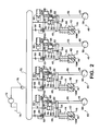
- Figure 2 is a schematic diagram of a bank of four engine cylinders with each of which a mechanism of the present disclosure is associated.
- Figure 3 is an enlarged diagram of one of the cylinders and its associated mechanism at a time in the engine cycle when the cylinder intake valve is open.
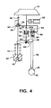
- Figure 4 is a diagram similar to Figure 3 but at a different time in the engine cycle.
- Figure 5 is a partial longitudinal cross section view showing one of the devices of the mechanism by itself.
- Figure 6 is a transverse cross section view taken along line 6-6 in Figure 5 .
- Figures 7 , 8, and 9 are respective graph plots useful in explaining certain aspects of the operation of the mechanism during an engine cycle.
- Figure 1 illustrates a portion of an internal combustion engine 10, such as a diesel engine that powers a motor vehicle.
- Engine 10 comprises an intake system 12 through which charge air is delivered to an intake manifold 14 of engine 10.
- Charge air enters each engine cylinder 16 from manifold 14 via a corresponding intake valve 18.
- Individual fuel injectors 20 inject diesel fuel into individual engine cylinders in properly timed relation to engine operation. The injected fuel combusts in the presence of the hot compressed air in the cylinder to force a power stroke of a piston 22 connected by a rod 24 with a crankshaft 26.
- Engine 10 further comprises an exhaust system 28 for conveyance of exhaust gases created by combustion within the engine cylinders from the engine. Exhaust gases pass out of each cylinder via a respective exhaust valve 30.
- the normally closed intake and exhaust valves at each cylinder are opened and closed at appropriate times during the engine cycle by a mechanism, designated in the drawing by the reference numeral 32 for intake valve 18 and by the reference numeral 34 for exhaust valve 30.
- ECM 36 that possesses digital processing capability is associated with engine 10.
- ECM 36 comprises one or more processors that process data from various input data signal sources in accordance with programmed algorithms to develop certain data for signals used in the performance of various functions associated with operation of engine 10.
- Turbocharging of engine 10 is accomplished by a turbocharger that is not specifically shown.
- Engine 10 also contains an EGR system, which too is not specifically shown.
- Figure 2 shows four mechanisms 40, each for a respective engine cylinder.
- the illustrated positions of movable elements of various devices in each mechanism may not necessarily be the exact ones that they would have during engine operation because Figure 2 is intended simply to introduce the various devices and how they are arranged in each mechanism. Actual operation of moving elements in a mechanism will be described later in connection with other Figures. It is to be understood that because the cylinders have a particular firing order, the engine cycles of the cylinders are also out of phase causing the positions of moving elements in each mechanism 40 to also be out of phase with those of moving elements of the other mechanisms.
- Each intake valve 18 has a head 18H that seats on and unseats from a valve seat in a cylinder head 42.
- a spring 44 biases each head 18H to seat on the respective seat closing the respective cylinder to intake manifold 14.
- a valve opening mechanism 46 for each intake valve comprises a respective cam 48 on a camshaft 50 and a respective rocker 52.
- Each rocker 52 can pivot about a relocatable axis 54 and comprises opposite ends, one of which provides a point of interaction between the rocker and the respective intake valve and the other of which provides a point of interaction with an end of a push rod 56 that is operated by the respective cam 48.
- Each mechanism 40 comprises a hydraulic actuator 58, a fast-acting control valve 60, an accumulator 62, a hydraulic snubber 64, and two check valves 66, 68.
- Hydraulic fluid used by mechanism 40 is provided by oil from an oil rail 70 that, depending on the type of fuel injectors, may also supply oil to fuel injectors 20 for injecting fuel into cylinders 16 and that is kept filled with pressurized oil by a pump 72 that pumps oil from a sump 74 into the oil rail through a check valve 76.
- Actuator 58 comprises a variable volume chamber 78 that expands by pushing an internal piston 80 toward one end of the actuator when oil is introduced into the chamber.
- a piston rod 82 protrudes from that one end and moves with piston 80, increasingly extending as the chamber expands.
- a distal end of piston rod 82 is pinned to rocker 52 by a cylindrical pin 84 whose longitudinal axis is coincident with axis 54.
- Actuator chamber 78 communicates with one port 86 of valve 60. Another port 88 of valve 60 communicates with accumulator 62, oil rail 70, and one port 90 of snubber 64. Oil from oil rail 70 is supplied to another port 92 of snubber 64 through check valve 68. Oil from oil rail 70 is also supplied to actuator chamber 78 through check valve 66.
- Valve 60 is spring-biased closed to block flow between port 90 and port 92, but comprises an electric operator 60A that when operated by an electric signal opens the valve so that fluid can flow between its two ports.
- FIG. 2 shows each cylinder intake valve 18 closed, each push rod 56 off the lobe of the respective cam 48, and moving parts of each mechanism in identical positions, a showing that doesn't reflect the different firing order discussed earlier. Operation of mechanism 40 for one cylinder starting from the position shown in Figure 2 will now be discussed with reference to Figures 3 and 4 .
- actuator 58 were not hydraulically locked, the upward motion of pushrod 56 would cause rocker 52 to act as a second class lever because the lack of constraint of axis 54 would instead cause rocker 52 to pivot about its point of interaction with valve 18, thereby moving axis 54 until an upward travel limit for the axis is reached.
- valve 18 cannot open early.
- FIG. 3 shows valve 18 essentially fully open.
- each mechanism 40 provides early IVC for each engine cylinder by allowing pin 84 to relocate.
- early IVC is initiated by a signal from ECM 36 being effective on electric operator 60A to cause control valve 60 to open, thereby unlocking actuator 58 to allow pin 84 to relocate.
- port 86 open to port 88 oil in actuator chamber 78 is forced out through valve 60 because axis 54, having become unlocked with the unlocking of actuator 58, now enables rocker 52 to act as a second class lever with spring 44 pivoting the rocker clockwise about the rocker's point of interaction with push rod 56.
- rocker 52 being pivoted in this way, piston rod 82 is forced to retract into actuator 58, pushing piston 80 to force oil out of chamber 58 as the chamber volume contracts.
- accumulator 62 can immediately accept the oil being forced out of actuator 58 regardless of whatever ability oil rail 70 may have at the time to accept oil because it too is open to chamber 78 through open valve 60.
- the fluid that is accepted by accumulator 62 becomes available for re-use, as will be more fully explained shortly.
- Figure 4 shows valve 18 seated closed after early IVC resulting from the unlocking of actuator 58 as explained above, with pin 84 having moved upward a distance 94 from the position shown in Figure 3 to the position marked 84' in Figure 4 .
- pin 84 returns from the position 84' in Figure 4 to the position in Figure 3 in the following way.
- Valve 60 remains open as cam 48 continues turning. Having stored the oil that was forced out of actuator 58, accumulator 62, now functions to restore that oil by forcing it through valve 60 into actuator 58 to move pin 84, and hence rocker axis 54, to the Figure 3 position as push rod 56 comes off the cam lobe to allow the push rod to move downwardly and thereby enable the accumulator to force oil into the actuator to extend piston rod 82. Once the push rod has come entirely off the cam lobe, valve 60 is closed to hydraulically lock actuator 58 with axis 54 in the Figure 3 position.
- Accumulator 62 thereby not only minimizes the mechanism's consumption of oil from oil rail 70, but by providing the ability to quickly take in oil, it also enables prompt early IVC when valve 60 opens.
- snubber 64 While snubber port 90 is also exposed directly to actuator chamber 78 through open valve 60, snubber 64 typically doesn't affect the initial early closing of valve 18. Snubber 64 functions to snub the final motion of valve 18 toward closing on the valve seat in cylinder head 42, as will be explained in more detail with reference to Figures 5 and 6 .
- Snubber 64 comprises a variable volume chamber 96 cooperatively defined by a snubbing element 98 and by a body 100 with respect to which the snubbing element is extendable and retractable.
- Snubbing element 98 comprises a head end 102 that protrudes from body 100 for interaction with intake valve 18 and a tail end 104 that remains inside body 100 as snubbing element 98 extends and retracts.
- Snubber 64 provides a restriction to flow of oil between port 90 and port 92 for snubbing closing motion of valve 18 as the valve is approaching the valve seat. While the restriction generally increases as the valve increasingly nears the seat, it may not increase uniformly.
- the manner in which the restriction changes is set by a scheduling aperture geometry that extends through a hollow cylindrical wall portion 106 of tail end 104 that moves across an undercut 108 in an inner surface of a cylindrical wall portion 110 of snubber body 100 surrounding wall portion 106 as snubbing element 98 is increasingly retracted.
- the scheduling aperture geometry comprises four discrete through-apertures 112, 114A, 114B, 116.
- Wall portion 106 is closed to head end 102, and consequently surrounds a volume that forms a lower portion of snubber chamber 96 whose upper portion is surrounded by wall portion 110 of body 100 and closed by a top end wall 118.
- Port 92 is at the top of end wall 118 and communicated to chamber 96 through a passage 120 in end wall 118.
- Undercut 108 extends 360° around wall portion 110 and has a constant axial dimension throughout.
- a passage 122 in wall portion 110 communicates undercut 108 to port 90.
- the four through-apertures are arranged in a pattern where each is offset circumferentially from the others, with through-apertures 114A, 114B being diametrically opposite each other and having identical open areas.
- Through-aperture 112 is more distant from head end 102 than are through-apertures 114A, 114B and also has an open area that is greater than the sum of the open areas of through-apertures 114A, 114B.
- Figure 6 shows through-aperture 114A offset counterclockwise and through-aperture 114B offset clockwise from through-aperture 112.
- Figure 5 shows through-apertures 114A, 114B more distant from head end 102 than through-aperture 116, and each also having an open area that is greater than that of through-aperture 116.
- Figure 6 shows through-aperture 116 offset counterclockwise from through-aperture 114A.
- snubber body 100 has an opening 124 through which head end 102 protrudes.
- a spring 126 biases snubbing element 98 so that a shoulder 128 of the element is forced against a lip 130 of the body surrounding opening 124 to set the maximum distance that head end 102 can protrude.
- chamber 96 is open to undercut 108 only via through-aperture 112.
- valve closing motion is snubbed in a manner that assures substantially constant landing speed on the valve seat because through-aperture 116 is the only one through which oil can pass during a final increment of valve travel approaching re-seating and when the valve finally re-seats after having traveled the distance indicted by the numeral 132.
- Figure 7 shows a graph plot containing a trace 133 representative of the relationship of the open area of the snubber scheduling geometry presented to undercut 108, i.e. the restriction between ports 90 and 92, as a function of linear displacement of snubbing element 98.
- the horizontal axis represents snubbing element displacement, or stroke, and the vertical axis, the corresponding open area of the scheduling geometry presented to undercut 108.
- the graph plot is normalized rather than dimensioned.
- Trace 133 begins at "zero” and ends at “one” along the horizontal axis At its beginning, trace 133 has a "non-zero" value corresponding to the open area of through-aperture 116.
- trace 133 has a value "one" corresponding to shoulder 128 abutting lip 130.
- Constant intake valve landing speed that is essentially independent of engine speed is achieved by locating through-aperture 116 such that it is the only through-aperture in the scheduling geometry that is in registration with undercut 108 during a final increment of valve travel before landing. In this way the valve can properly retract under a variable range of tolerance stack-ups and valve growth while landing speed is substantially constant throughout the engine speed range and valve duration command.
- snubbing element 98 can have a relatively long stroke beyond the valve landing ramp, and hence a longer time during which it can interact with the valve closing motion, effects such as contact stresses, pressure fluctuations, and/or noise that might occur during a shorter interaction time resulting may be mitigated or avoided.
- Figure 8 shows the effect of accumulator 62 on pressure in snubber chamber 96.
- a first trace 134 shows that oil rail 70 is incapable of satisfying the expanding volume of chamber 96 as valve 18 opens because a partial vacuum is drawn in chamber 96, i.e. cavitation occurs, during the portion of the engine cycle marked 136.
- Accumulator 62 mitigates the cavitation by providing an additional oil source to chamber 96 through the snubber's variable restriction that becomes less restrictive as snubbing element 98 increasingly extends.
- Trace 138 shows that no vacuum is drawn in the snubber chamber.
- FIG. 9 graphically portrays a portion of an engine cycle with and without early IVC.
- a trace 140 depicts valve motion that occurs without early IVC by keeping actuator 58 hydraulically locked.
- a trace 142 shows control valve 60 opening to cause early IVC.
- a trace 144 shows that valve 18 begins closing early and re-seats closed earlier than in the absence of early IVC.
- Valve 60 is allowed to close and relock actuator 58 only after valve 18 has re-seated.
- a trace 145 shows snubbing element 98 extending as the intake valve opens until shoulder 128 abuts lip 130 at full extension.
- Mechanism 40 can be fabricated as a "bolt-on" unit for association with an engine valve train. Fast-acting valve 60 and actuator 58 coact to promptly begin closing the intake valve in response to a closing command.
- axis 54 allows a mechanism 40 to function a) both as a hydraulic lifter in the absence of an IVC-adjust command and b) as a retracting element to close the respective intake valve at a rate determined by geometries of the respective actuator 58, fast-acting valve 60, and snubber 64.
- the landing speed of the intake valve is set or controlled by one or a combination of a control algorithm applied to valve 60 and of a specific snubber design characterized by a unique scheduling area geometry, where the area prescribes a constant landing speed and the "late" hole, i.e. through-aperture 116, ensures that the intake valve can land under all conditions.
- snubbing element 98 can have a relatively long linear stroke and avoid the cavitation exemplified by trace 134 in Figure 8 . Because the accumulator has exposure to both the actuator 58 and oil rail 70, mechanism 40 uses relatively little "new" oil during each engine cycle while operating at speeds appropriate for fast-acting valve 60.
- engine 10 If engine 10 is shut down for some length of time, some leakage may occur, resulting in loss of some pressure and the formation of air bubbles in the hydraulic system of mechanism 40, including actuator 58. To mitigate or even totally avoid the effect of such air bubbles on performance of the mechanism, it and the engine are operated in a particular way before the engine commences running under its own power.
- fast-acting valve 60 is opened at an appropriate crank angle of the cycle for the corresponding engine cylinder to invoke some degree of early IVC for the purpose of purging air from actuator 58.
- the opening of valve 60 unlocks actuator 58 so that the force of spring 44 acting on rocker 52 will force some oil, and any entrained air that the oil may contain, out of actuator 58 and into accumulator 62 and/or oil rail 70.
- fast-acting valve 60 stays open long enough before being closed to allow accumulator 62 to push oil back through valve 60 and into actuator 58 to cause pin 84 to return to the position of Figure 3 . Continuation of this process during engine cranking restores lost pressure and eliminates air bubbles.
- the degree of early IVC for the purpose of air purge is controlled so as not to impair the ability to start the engine.
- air purge of actuator 58 can be continued by opening fast-acting valve 60 earlier in the engine cycle for the particular cylinder to allow for the idle speed being greater than the cranking speed.
- the air purge strategy for mechanism 40 ends, and mechanism 40 is controlled by whatever other variable valve actuation (WA) strategy or strategies in ECM 36 is or are appropriate for particular engine operating conditions.
- WA variable valve actuation
Landscapes
- Engineering & Computer Science (AREA)
- Mechanical Engineering (AREA)
- General Engineering & Computer Science (AREA)
- Valve Device For Special Equipments (AREA)
- Output Control And Ontrol Of Special Type Engine (AREA)
Applications Claiming Priority (1)
| Application Number | Priority Date | Filing Date | Title |
|---|---|---|---|
| US12/540,828 US8069828B2 (en) | 2009-08-13 | 2009-08-13 | Intake valve closing hydraulic adjuster |
Publications (3)
| Publication Number | Publication Date |
|---|---|
| EP2295737A2 true EP2295737A2 (de) | 2011-03-16 |
| EP2295737A3 EP2295737A3 (de) | 2011-06-29 |
| EP2295737B1 EP2295737B1 (de) | 2012-09-19 |
Family
ID=43414753
Family Applications (1)
| Application Number | Title | Priority Date | Filing Date |
|---|---|---|---|
| EP10008441A Not-in-force EP2295737B1 (de) | 2009-08-13 | 2010-08-12 | Hydraulische Einstellvorrichtung zum Schließen eines Ansaugventils |
Country Status (5)
| Country | Link |
|---|---|
| US (1) | US8069828B2 (de) |
| EP (1) | EP2295737B1 (de) |
| JP (1) | JP2011038526A (de) |
| CN (1) | CN101994536B (de) |
| BR (1) | BRPI1003070A2 (de) |
Cited By (1)
| Publication number | Priority date | Publication date | Assignee | Title |
|---|---|---|---|---|
| DE102017116979B4 (de) | 2016-09-16 | 2021-10-07 | Suzuki Motor Corporation | Variables Ventilsystem für einen Verbrennungsmotor |
Families Citing this family (10)
| Publication number | Priority date | Publication date | Assignee | Title |
|---|---|---|---|---|
| DE102008049181A1 (de) * | 2008-09-26 | 2010-04-01 | Schaeffler Kg | Elektrohydraulische Ventilsteuerung |
| CN103443408A (zh) | 2011-01-27 | 2013-12-11 | 史古德利集团公司 | 具有阀停用的无效运动可变阀致动系统 |
| WO2012103401A2 (en) | 2011-01-27 | 2012-08-02 | Scuderi Group, Llc | Lost-motion variable valve actuation system with cam phaser |
| US9109468B2 (en) | 2012-01-06 | 2015-08-18 | Scuderi Group, Llc | Lost-motion variable valve actuation system |
| CN102953781B (zh) * | 2012-10-24 | 2014-12-10 | 上海交通大学 | 用于发动机进气门升程调节的机械式移动杆滑动系统 |
| CN102979593B (zh) * | 2012-11-22 | 2014-12-10 | 上海交通大学 | 移动杆左右移动式气门升程调节装置 |
| CN102996197B (zh) * | 2012-11-22 | 2014-12-10 | 上海交通大学 | 移动杆上下移动式气门升程调节机构 |
| EP2971636A1 (de) | 2013-03-15 | 2016-01-20 | Scuderi Group, Inc. | Motoren mit geteiltem takt mit direkteinspritzung |
| US9279350B2 (en) * | 2014-05-27 | 2016-03-08 | Caterpillar Inc. | Intake valve closure control for dual-fuel engines |
| CN115573954B (zh) * | 2022-09-09 | 2025-11-28 | 农业农村部南京农业机械化研究所 | 一种电液仿形系统 |
Family Cites Families (28)
| Publication number | Priority date | Publication date | Assignee | Title |
|---|---|---|---|---|
| US3678906A (en) | 1970-12-04 | 1972-07-25 | Ford Motor Co | Damped valve train system |
| US4483283A (en) | 1983-05-13 | 1984-11-20 | Hausknecht Louis A | Variable valve control system with dampener assembly |
| US5158048A (en) | 1992-04-02 | 1992-10-27 | Siemens Automotive L.P. | Lost motion actuator |
| JPH0783013A (ja) | 1993-09-13 | 1995-03-28 | Nissan Motor Co Ltd | 内燃機関の可変動弁装置 |
| US5829397A (en) | 1995-08-08 | 1998-11-03 | Diesel Engine Retarders, Inc. | System and method for controlling the amount of lost motion between an engine valve and a valve actuation means |
| DE59507966D1 (de) * | 1995-10-03 | 2000-04-13 | Waertsilae Nsd Schweiz Ag Wint | Hydraulischer Ventilantrieb |
| JP2001518587A (ja) | 1997-08-28 | 2001-10-16 | ディーゼル エンジン リターダーズ,インコーポレイテッド | 油圧弁アクチュエータ |
| KR20010032345A (ko) | 1997-11-21 | 2001-04-16 | 디이젤 엔진 리타더스, 인코포레이티드 | 한정된 로스트 모션 태핏에서 밸브 시팅 속도를 한정하는장치 |
| US6510824B2 (en) | 1997-12-11 | 2003-01-28 | Diesel Engine Retarders, Inc. | Variable lost motion valve actuator and method |
| US6044815A (en) | 1998-09-09 | 2000-04-04 | Navistar International Transportation Corp. | Hydraulically-assisted engine valve actuator |
| US6786186B2 (en) | 1998-09-09 | 2004-09-07 | International Engine Intellectual Property Company, Llc | Unit trigger actuator |
| US6263842B1 (en) | 1998-09-09 | 2001-07-24 | International Truck And Engine Corporation | Hydraulically-assisted engine valve actuator |
| AU4364600A (en) | 1999-04-19 | 2000-11-02 | International Engine Intellectual Property Company, Llc | Fuel pressure delay cylinder |
| KR20020005007A (ko) | 1999-05-18 | 2002-01-16 | 인터내셔널 엔진 인터렉츄얼 프로퍼티 캄파니, 엘엘씨 | 양방향 이중 유압제어장치 |
| WO2001020150A1 (en) | 1999-09-17 | 2001-03-22 | Diesel Engine Retarders, Inc. | Captive volume accumulator for a lost motion system |
| US6467457B1 (en) | 1999-10-25 | 2002-10-22 | International Engine Intellectual Property Company, L.L.C. | Injector actuating fluid check and methods |
| US6539909B2 (en) | 2001-05-03 | 2003-04-01 | International Engine Intellectual Property Company, L.L.C. | Retractable seat valve and method for selective gas flow control in a combustion chamber |
| AT5399U1 (de) | 2001-09-25 | 2002-06-25 | Avl List Gmbh | Variabler ventiltrieb |
| US20030217713A1 (en) | 2002-01-30 | 2003-11-27 | Richardson Donald G. | Variable valve opening for an internal combustion engine |
| WO2003087544A2 (en) | 2002-04-08 | 2003-10-23 | Diesel Engine Retarders, Inc. | Compact lost motion system for variable valve actuation |
| US6978747B2 (en) | 2003-04-01 | 2005-12-27 | International Engine Intellectual Property Company, Llc | Hydraulic actuator cartridge for a valve |
| JP2004346806A (ja) * | 2003-05-21 | 2004-12-09 | Mitsubishi Electric Corp | バルブタイミング調整システム |
| US7228826B2 (en) * | 2003-12-23 | 2007-06-12 | Caterpillar Inc | Internal combustion engine valve seating velocity control |
| DE102005000621A1 (de) | 2005-01-03 | 2006-07-13 | Robert Bosch Gmbh | Verfahren zum Betreiben einer Brennkraftmaschine |
| ATE448387T1 (de) * | 2005-01-12 | 2009-11-15 | Volvo Lastvagnar Ab | Vorrichtung für einen verbrennungsmotor |
| US7168250B2 (en) | 2005-04-21 | 2007-01-30 | International Engine Intellectual Property Company, Llc | Engine valve system and method |
| US7347172B2 (en) | 2005-05-10 | 2008-03-25 | International Engine Intellectual Property Company, Llc | Hydraulic valve actuation system with valve lash adjustment |
| US7168396B1 (en) | 2005-09-15 | 2007-01-30 | International Engine Intellectual Property Company, Llc | Variable compression ratio strategy for improving combustion processes in alternative combustion compression ignition engines |
-
2009
- 2009-08-13 US US12/540,828 patent/US8069828B2/en active Active
-
2010
- 2010-08-12 EP EP10008441A patent/EP2295737B1/de not_active Not-in-force
- 2010-08-13 CN CN201010257236.5A patent/CN101994536B/zh not_active Expired - Fee Related
- 2010-08-13 JP JP2010194863A patent/JP2011038526A/ja active Pending
- 2010-08-13 BR BRPI1003070-0A patent/BRPI1003070A2/pt not_active Application Discontinuation
Non-Patent Citations (1)
| Title |
|---|
| None |
Cited By (1)
| Publication number | Priority date | Publication date | Assignee | Title |
|---|---|---|---|---|
| DE102017116979B4 (de) | 2016-09-16 | 2021-10-07 | Suzuki Motor Corporation | Variables Ventilsystem für einen Verbrennungsmotor |
Also Published As
| Publication number | Publication date |
|---|---|
| US8069828B2 (en) | 2011-12-06 |
| BRPI1003070A2 (pt) | 2012-04-24 |
| CN101994536B (zh) | 2012-12-12 |
| EP2295737B1 (de) | 2012-09-19 |
| EP2295737A3 (de) | 2011-06-29 |
| CN101994536A (zh) | 2011-03-30 |
| US20110036316A1 (en) | 2011-02-17 |
| JP2011038526A (ja) | 2011-02-24 |
Similar Documents
| Publication | Publication Date | Title |
|---|---|---|
| US8069828B2 (en) | Intake valve closing hydraulic adjuster | |
| US11459917B2 (en) | Cylinder deactivation energy waste management | |
| US7434556B2 (en) | Engine valve actuation system | |
| JP3670297B2 (ja) | 排気ガス再循環時のエンジンブレーキング及び/又は排気 | |
| US7556017B2 (en) | Twin needle valve dual mode injector | |
| KR100751607B1 (ko) | 내적 배기 가스 재순환 시스템 및 방법 | |
| EP2184451B1 (de) | Dieselmotor mit Nocken zum betätigen von Einlassventilen, welche einen Hauptnocken und einen Hilfsnocken, die miteinander verbunden sind, aufweisen | |
| EP2184452B1 (de) | Dieselmotor mit variabler Einlassventilbetätigung und einer internen Abgasrückführung | |
| US7523606B2 (en) | Parasitic load control system for exhaust temperature control | |
| US11377985B2 (en) | Switching tappet or a roller finger follower for compression release braking | |
| WO2014047643A1 (en) | Intgrated lost motion rocker brake with automatic reset | |
| US20070062193A1 (en) | Combustion engine including fluidically-controlled engine valve actuator | |
| JP2003328715A (ja) | エンジンバルブ作動システム | |
| EP1364113B1 (de) | Dieselmotor mit katalysator | |
| US20240360777A1 (en) | Rocker systems with cylinder deactivation and selective valve lift capabilities | |
| US20190277166A1 (en) | Variable valve drive with a sliding cam system for an internal combustion engine | |
| US20230313714A1 (en) | Systems and methods for lash adjustment and cylinder deactivation for internal combustion engines | |
| US20080127920A1 (en) | Variable engine valve actuation system having common rail | |
| FI124813B (fi) | Ohjausjärjestely ja menetelmä pakoventtiilin ohjaamiseksi | |
| US11454178B2 (en) | Method for controlling an internal combustion engine arrangement | |
| JPH0331890B2 (de) |
Legal Events
| Date | Code | Title | Description |
|---|---|---|---|
| PUAI | Public reference made under article 153(3) epc to a published international application that has entered the european phase |
Free format text: ORIGINAL CODE: 0009012 |
|
| AK | Designated contracting states |
Kind code of ref document: A2 Designated state(s): AL AT BE BG CH CY CZ DE DK EE ES FI FR GB GR HR HU IE IS IT LI LT LU LV MC MK MT NL NO PL PT RO SE SI SK SM TR |
|
| AX | Request for extension of the european patent |
Extension state: BA ME RS |
|
| PUAL | Search report despatched |
Free format text: ORIGINAL CODE: 0009013 |
|
| AK | Designated contracting states |
Kind code of ref document: A3 Designated state(s): AL AT BE BG CH CY CZ DE DK EE ES FI FR GB GR HR HU IE IS IT LI LT LU LV MC MK MT NL NO PL PT RO SE SI SK SM TR |
|
| AX | Request for extension of the european patent |
Extension state: BA ME RS |
|
| 17P | Request for examination filed |
Effective date: 20111229 |
|
| GRAP | Despatch of communication of intention to grant a patent |
Free format text: ORIGINAL CODE: EPIDOSNIGR1 |
|
| GRAS | Grant fee paid |
Free format text: ORIGINAL CODE: EPIDOSNIGR3 |
|
| GRAA | (expected) grant |
Free format text: ORIGINAL CODE: 0009210 |
|
| AK | Designated contracting states |
Kind code of ref document: B1 Designated state(s): AL AT BE BG CH CY CZ DE DK EE ES FI FR GB GR HR HU IE IS IT LI LT LU LV MC MK MT NL NO PL PT RO SE SI SK SM TR |
|
| REG | Reference to a national code |
Ref country code: GB Ref legal event code: FG4D |
|
| REG | Reference to a national code |
Ref country code: CH Ref legal event code: EP |
|
| REG | Reference to a national code |
Ref country code: IE Ref legal event code: FG4D |
|
| REG | Reference to a national code |
Ref country code: AT Ref legal event code: REF Ref document number: 576153 Country of ref document: AT Kind code of ref document: T Effective date: 20121015 |
|
| REG | Reference to a national code |
Ref country code: DE Ref legal event code: R096 Ref document number: 602010002810 Country of ref document: DE Effective date: 20121115 |
|
| PG25 | Lapsed in a contracting state [announced via postgrant information from national office to epo] |
Ref country code: NO Free format text: LAPSE BECAUSE OF FAILURE TO SUBMIT A TRANSLATION OF THE DESCRIPTION OR TO PAY THE FEE WITHIN THE PRESCRIBED TIME-LIMIT Effective date: 20121219 Ref country code: FI Free format text: LAPSE BECAUSE OF FAILURE TO SUBMIT A TRANSLATION OF THE DESCRIPTION OR TO PAY THE FEE WITHIN THE PRESCRIBED TIME-LIMIT Effective date: 20120919 Ref country code: LT Free format text: LAPSE BECAUSE OF FAILURE TO SUBMIT A TRANSLATION OF THE DESCRIPTION OR TO PAY THE FEE WITHIN THE PRESCRIBED TIME-LIMIT Effective date: 20120919 Ref country code: HR Free format text: LAPSE BECAUSE OF FAILURE TO SUBMIT A TRANSLATION OF THE DESCRIPTION OR TO PAY THE FEE WITHIN THE PRESCRIBED TIME-LIMIT Effective date: 20120919 |
|
| REG | Reference to a national code |
Ref country code: NL Ref legal event code: VDEP Effective date: 20120919 |
|
| REG | Reference to a national code |
Ref country code: AT Ref legal event code: MK05 Ref document number: 576153 Country of ref document: AT Kind code of ref document: T Effective date: 20120919 |
|
| REG | Reference to a national code |
Ref country code: LT Ref legal event code: MG4D Effective date: 20120919 |
|
| PG25 | Lapsed in a contracting state [announced via postgrant information from national office to epo] |
Ref country code: GR Free format text: LAPSE BECAUSE OF FAILURE TO SUBMIT A TRANSLATION OF THE DESCRIPTION OR TO PAY THE FEE WITHIN THE PRESCRIBED TIME-LIMIT Effective date: 20121220 Ref country code: SI Free format text: LAPSE BECAUSE OF FAILURE TO SUBMIT A TRANSLATION OF THE DESCRIPTION OR TO PAY THE FEE WITHIN THE PRESCRIBED TIME-LIMIT Effective date: 20120919 Ref country code: LV Free format text: LAPSE BECAUSE OF FAILURE TO SUBMIT A TRANSLATION OF THE DESCRIPTION OR TO PAY THE FEE WITHIN THE PRESCRIBED TIME-LIMIT Effective date: 20120919 Ref country code: SE Free format text: LAPSE BECAUSE OF FAILURE TO SUBMIT A TRANSLATION OF THE DESCRIPTION OR TO PAY THE FEE WITHIN THE PRESCRIBED TIME-LIMIT Effective date: 20120919 |
|
| PG25 | Lapsed in a contracting state [announced via postgrant information from national office to epo] |
Ref country code: RO Free format text: LAPSE BECAUSE OF FAILURE TO SUBMIT A TRANSLATION OF THE DESCRIPTION OR TO PAY THE FEE WITHIN THE PRESCRIBED TIME-LIMIT Effective date: 20120919 Ref country code: ES Free format text: LAPSE BECAUSE OF FAILURE TO SUBMIT A TRANSLATION OF THE DESCRIPTION OR TO PAY THE FEE WITHIN THE PRESCRIBED TIME-LIMIT Effective date: 20121230 Ref country code: NL Free format text: LAPSE BECAUSE OF FAILURE TO SUBMIT A TRANSLATION OF THE DESCRIPTION OR TO PAY THE FEE WITHIN THE PRESCRIBED TIME-LIMIT Effective date: 20120919 Ref country code: CZ Free format text: LAPSE BECAUSE OF FAILURE TO SUBMIT A TRANSLATION OF THE DESCRIPTION OR TO PAY THE FEE WITHIN THE PRESCRIBED TIME-LIMIT Effective date: 20120919 Ref country code: EE Free format text: LAPSE BECAUSE OF FAILURE TO SUBMIT A TRANSLATION OF THE DESCRIPTION OR TO PAY THE FEE WITHIN THE PRESCRIBED TIME-LIMIT Effective date: 20120919 Ref country code: IS Free format text: LAPSE BECAUSE OF FAILURE TO SUBMIT A TRANSLATION OF THE DESCRIPTION OR TO PAY THE FEE WITHIN THE PRESCRIBED TIME-LIMIT Effective date: 20130119 Ref country code: BE Free format text: LAPSE BECAUSE OF FAILURE TO SUBMIT A TRANSLATION OF THE DESCRIPTION OR TO PAY THE FEE WITHIN THE PRESCRIBED TIME-LIMIT Effective date: 20120919 |
|
| PG25 | Lapsed in a contracting state [announced via postgrant information from national office to epo] |
Ref country code: PL Free format text: LAPSE BECAUSE OF FAILURE TO SUBMIT A TRANSLATION OF THE DESCRIPTION OR TO PAY THE FEE WITHIN THE PRESCRIBED TIME-LIMIT Effective date: 20120919 Ref country code: PT Free format text: LAPSE BECAUSE OF FAILURE TO SUBMIT A TRANSLATION OF THE DESCRIPTION OR TO PAY THE FEE WITHIN THE PRESCRIBED TIME-LIMIT Effective date: 20130121 Ref country code: SK Free format text: LAPSE BECAUSE OF FAILURE TO SUBMIT A TRANSLATION OF THE DESCRIPTION OR TO PAY THE FEE WITHIN THE PRESCRIBED TIME-LIMIT Effective date: 20120919 |
|
| PG25 | Lapsed in a contracting state [announced via postgrant information from national office to epo] |
Ref country code: AT Free format text: LAPSE BECAUSE OF FAILURE TO SUBMIT A TRANSLATION OF THE DESCRIPTION OR TO PAY THE FEE WITHIN THE PRESCRIBED TIME-LIMIT Effective date: 20120919 |
|
| PLBE | No opposition filed within time limit |
Free format text: ORIGINAL CODE: 0009261 |
|
| STAA | Information on the status of an ep patent application or granted ep patent |
Free format text: STATUS: NO OPPOSITION FILED WITHIN TIME LIMIT |
|
| PG25 | Lapsed in a contracting state [announced via postgrant information from national office to epo] |
Ref country code: DK Free format text: LAPSE BECAUSE OF FAILURE TO SUBMIT A TRANSLATION OF THE DESCRIPTION OR TO PAY THE FEE WITHIN THE PRESCRIBED TIME-LIMIT Effective date: 20120919 Ref country code: BG Free format text: LAPSE BECAUSE OF FAILURE TO SUBMIT A TRANSLATION OF THE DESCRIPTION OR TO PAY THE FEE WITHIN THE PRESCRIBED TIME-LIMIT Effective date: 20121219 |
|
| 26N | No opposition filed |
Effective date: 20130620 |
|
| PG25 | Lapsed in a contracting state [announced via postgrant information from national office to epo] |
Ref country code: IT Free format text: LAPSE BECAUSE OF FAILURE TO SUBMIT A TRANSLATION OF THE DESCRIPTION OR TO PAY THE FEE WITHIN THE PRESCRIBED TIME-LIMIT Effective date: 20120919 |
|
| REG | Reference to a national code |
Ref country code: DE Ref legal event code: R097 Ref document number: 602010002810 Country of ref document: DE Effective date: 20130620 |
|
| PGFP | Annual fee paid to national office [announced via postgrant information from national office to epo] |
Ref country code: DE Payment date: 20130902 Year of fee payment: 4 |
|
| PG25 | Lapsed in a contracting state [announced via postgrant information from national office to epo] |
Ref country code: CY Free format text: LAPSE BECAUSE OF FAILURE TO SUBMIT A TRANSLATION OF THE DESCRIPTION OR TO PAY THE FEE WITHIN THE PRESCRIBED TIME-LIMIT Effective date: 20120919 |
|
| PGFP | Annual fee paid to national office [announced via postgrant information from national office to epo] |
Ref country code: FR Payment date: 20130725 Year of fee payment: 4 |
|
| PG25 | Lapsed in a contracting state [announced via postgrant information from national office to epo] |
Ref country code: MC Free format text: LAPSE BECAUSE OF FAILURE TO SUBMIT A TRANSLATION OF THE DESCRIPTION OR TO PAY THE FEE WITHIN THE PRESCRIBED TIME-LIMIT Effective date: 20120919 |
|
| REG | Reference to a national code |
Ref country code: IE Ref legal event code: MM4A |
|
| PG25 | Lapsed in a contracting state [announced via postgrant information from national office to epo] |
Ref country code: IE Free format text: LAPSE BECAUSE OF NON-PAYMENT OF DUE FEES Effective date: 20130812 |
|
| REG | Reference to a national code |
Ref country code: DE Ref legal event code: R119 Ref document number: 602010002810 Country of ref document: DE |
|
| REG | Reference to a national code |
Ref country code: CH Ref legal event code: PL |
|
| GBPC | Gb: european patent ceased through non-payment of renewal fee |
Effective date: 20140812 |
|
| PG25 | Lapsed in a contracting state [announced via postgrant information from national office to epo] |
Ref country code: CH Free format text: LAPSE BECAUSE OF NON-PAYMENT OF DUE FEES Effective date: 20140831 Ref country code: LI Free format text: LAPSE BECAUSE OF NON-PAYMENT OF DUE FEES Effective date: 20140831 |
|
| REG | Reference to a national code |
Ref country code: DE Ref legal event code: R119 Ref document number: 602010002810 Country of ref document: DE Effective date: 20150303 |
|
| PG25 | Lapsed in a contracting state [announced via postgrant information from national office to epo] |
Ref country code: SM Free format text: LAPSE BECAUSE OF FAILURE TO SUBMIT A TRANSLATION OF THE DESCRIPTION OR TO PAY THE FEE WITHIN THE PRESCRIBED TIME-LIMIT Effective date: 20120919 |
|
| REG | Reference to a national code |
Ref country code: FR Ref legal event code: ST Effective date: 20150430 |
|
| PG25 | Lapsed in a contracting state [announced via postgrant information from national office to epo] |
Ref country code: MT Free format text: LAPSE BECAUSE OF FAILURE TO SUBMIT A TRANSLATION OF THE DESCRIPTION OR TO PAY THE FEE WITHIN THE PRESCRIBED TIME-LIMIT Effective date: 20120919 Ref country code: TR Free format text: LAPSE BECAUSE OF FAILURE TO SUBMIT A TRANSLATION OF THE DESCRIPTION OR TO PAY THE FEE WITHIN THE PRESCRIBED TIME-LIMIT Effective date: 20120919 |
|
| PG25 | Lapsed in a contracting state [announced via postgrant information from national office to epo] |
Ref country code: GB Free format text: LAPSE BECAUSE OF NON-PAYMENT OF DUE FEES Effective date: 20140812 Ref country code: LU Free format text: LAPSE BECAUSE OF NON-PAYMENT OF DUE FEES Effective date: 20130812 Ref country code: DE Free format text: LAPSE BECAUSE OF NON-PAYMENT OF DUE FEES Effective date: 20150303 Ref country code: HU Free format text: LAPSE BECAUSE OF FAILURE TO SUBMIT A TRANSLATION OF THE DESCRIPTION OR TO PAY THE FEE WITHIN THE PRESCRIBED TIME-LIMIT; INVALID AB INITIO Effective date: 20100812 Ref country code: MK Free format text: LAPSE BECAUSE OF FAILURE TO SUBMIT A TRANSLATION OF THE DESCRIPTION OR TO PAY THE FEE WITHIN THE PRESCRIBED TIME-LIMIT Effective date: 20120919 |
|
| PG25 | Lapsed in a contracting state [announced via postgrant information from national office to epo] |
Ref country code: FR Free format text: LAPSE BECAUSE OF NON-PAYMENT OF DUE FEES Effective date: 20140901 |
|
| PG25 | Lapsed in a contracting state [announced via postgrant information from national office to epo] |
Ref country code: AL Free format text: LAPSE BECAUSE OF FAILURE TO SUBMIT A TRANSLATION OF THE DESCRIPTION OR TO PAY THE FEE WITHIN THE PRESCRIBED TIME-LIMIT Effective date: 20120919 |