EP2295020A2 - Disposal of Human Remains - Google Patents
Disposal of Human Remains Download PDFInfo
- Publication number
- EP2295020A2 EP2295020A2 EP20100195320 EP10195320A EP2295020A2 EP 2295020 A2 EP2295020 A2 EP 2295020A2 EP 20100195320 EP20100195320 EP 20100195320 EP 10195320 A EP10195320 A EP 10195320A EP 2295020 A2 EP2295020 A2 EP 2295020A2
- Authority
- EP
- European Patent Office
- Prior art keywords
- coffin
- cadaver
- receptacle
- dissolvable
- chamber
- Prior art date
- Legal status (The legal status is an assumption and is not a legal conclusion. Google has not performed a legal analysis and makes no representation as to the accuracy of the status listed.)
- Granted
Links
Images


Classifications
-
- B—PERFORMING OPERATIONS; TRANSPORTING
- B09—DISPOSAL OF SOLID WASTE; RECLAMATION OF CONTAMINATED SOIL
- B09B—DISPOSAL OF SOLID WASTE
- B09B3/00—Destroying solid waste or transforming solid waste into something useful or harmless
- B09B3/0075—Disposal of medical waste
-
- A—HUMAN NECESSITIES
- A61—MEDICAL OR VETERINARY SCIENCE; HYGIENE
- A61G—TRANSPORT, PERSONAL CONVEYANCES, OR ACCOMMODATION SPECIALLY ADAPTED FOR PATIENTS OR DISABLED PERSONS; OPERATING TABLES OR CHAIRS; CHAIRS FOR DENTISTRY; FUNERAL DEVICES
- A61G17/00—Coffins; Funeral wrappings; Funeral urns
- A61G17/007—Coffins; Funeral wrappings; Funeral urns characterised by the construction material used, e.g. biodegradable material; Use of several materials
- A61G17/0136—Plastic material
-
- B—PERFORMING OPERATIONS; TRANSPORTING
- B09—DISPOSAL OF SOLID WASTE; RECLAMATION OF CONTAMINATED SOIL
- B09B—DISPOSAL OF SOLID WASTE
- B09B3/00—Destroying solid waste or transforming solid waste into something useful or harmless
-
- A—HUMAN NECESSITIES
- A61—MEDICAL OR VETERINARY SCIENCE; HYGIENE
- A61G—TRANSPORT, PERSONAL CONVEYANCES, OR ACCOMMODATION SPECIALLY ADAPTED FOR PATIENTS OR DISABLED PERSONS; OPERATING TABLES OR CHAIRS; CHAIRS FOR DENTISTRY; FUNERAL DEVICES
- A61G2203/00—General characteristics of devices
- A61G2203/70—General characteristics of devices with special adaptations, e.g. for safety or comfort
- A61G2203/90—General characteristics of devices with special adaptations, e.g. for safety or comfort biodegradable
Definitions
- the present invention relates to the disposal of human remains.
- the invention relates to disposal by alkaline hydrolysis.
- a coffin for use in on alkaline hydrolysis process, an alkaline hydrolysis unit and a method and system for disposing of a cadaver are also described.
- cremation Due to a lack of suitable and accessible land and the high costs involved, cremation is becoming preferable to burial
- cremation causes harmtul emissions in the form of dioxins and mercury.
- Mercury is big problem and in Europa, there is legislation pending to force crematoria to filter abate their emission, This is expensive and also requires very bulky equipment that takes up a lot of room.
- a further problem with cremation is that it uses a lot of gas, and produces large amounts of carbon dioxide, a greenhouse gas , which contributes to global warming.
- a further disadvantage of cremation is the organic building blocks that make up the body and come from the ecosystem are lost forever during the burning process.
- a coffin for use in an alkaline hydrolysis process comprising a dissolvable receptacle for a cadaver, the dissolvable receptacle being dissolvable in the alkaline hydrolysis process.
- ffin we mean any receptacle adapted to receive a cadaver.
- the term “coffin” is not limited to boxes, but can also encompass other cadaver receptacles, such as bags and rigid/flexible containers of non-cuboid shapes, as will be explained.
- Substantially all of the dissolvable receptacle is decomposable in the akaline hydrolysis process, together with the cadaver.
- the coffin is full dissolvable in the alkaline hydrolysis process.
- the coffin is provided with an outer casing.
- the outer casing typically resembles a conventional, wooden coffin, for presentation to the public, and is removed prior to the alkaline hydrolysis process.
- the outer casing comprises one or more wooden panels sized to at least partially surround the coffin. The panels may be securable to the coffin or to a support frame used with the coffin.
- the dissolvable recaptacle comprises one or more of silk, wool, or a bioplastic material.
- the entire dissolvable receptacle is bioplaslic.
- Bioplastics are made from organic sources, such as plant starch and sugar cane, instead of from petroleum. Once disposed of, many bioplastics will safely and naturally biodegrade. Most or all bioplastic materials are fully dissolvable by alkaline hydrolysis.
- bioplastic materials include that they may be strong, waterproof, light, simple to manufacture, and inexpensive. Waterproof embodiments do not require an additional waterproof liner. Additionally, the fact that bioplastic materials dissolve with the body makes them environmentally-friendly, since they willl not end up in landtill sites, and they do not require any additional expenditure of energy to destroy.
- a bioplastic coffin also allows more rapid emptying and cleaning of the alkaline hydrolysis unit
- the bioplastic coffin comprises a substantially rigid container, which may or may not have a lid or cover.
- a suitable bioplastic material for forming such a container is known as "Mater-Bi TF01 U/095R" and is available from Novamont SpA, Via Fauser, 8 I-28100 Novara, Italy.
- substantially rigid is to be construed to mean solid in the sense of a box, in contrast to the more cloth-like flexibllity of a bag or fabric. Hence,” substantially rigid” encompasses box-like containers of any shape, made from resilent materials.
- the container is injection-moulded.
- the coffin may be formed in any required shape.
- the coffin could be formed as a hollow cuboid box, as is conventional.
- other shapes can be used, for example more closely following the contours of a human body,
- the shape of the coffin may be designed to co-operate with the shape of the alkaline hydrolysis unit in which it will be used.
- the container may have any desired colour and optionally may be coloured to imitate wood, for aesthetic appeal.
- the coffin may comprise a flexible bag, instead of a substantially rigid container.
- the bioplastic material could be a dissolvable starch based biopolymer, such as a "Mater-Bi TM themoplastic biodegradable polymer” that comprises starch, polyesters and plasticizers. This material is available from Novamont SpA, Via Fauser, 8 I-28100. Novara, Italy, Such a bioplastic bag may be formed with very thin walls, whilst still being strong enough to carry a cadaver and still being waterproof. Alternatively, bags of silk or wool or other dissolvable materials could be used.
- the bag is an open bag, or a closeable bag which can be opened, to allow the cadaver to be viewed.
- the bag may be closeable (e.g. by a zip) such that the dissolvable receptacle fully surrounds and encloses the cadaver.
- the zip also provides the tension required to form a "tent" type design that fully hides that cadaver
- the coffin also includes a waterproof liner that is adapted to fit within or around the dissolvable, receptacle.
- the waterproof linger prevents body fluids from leaking out of the dissolvable receptacle.
- the waterproof liner can comprise an open bag (to allow viewing of the cadaver), or a fully sealable, closed, bag.
- Embodiments comprising a closed bag can be used for cadavers which have an infectious disease.
- the waterproof liner comprises a dissolvable starch based biopolymer material, for example a "Mater-BI TM thermoplastic biodegradable polymer comprising starch, polyesters and plasticizers.
- the waterproof liner is typically sewn or otherwise attached to the dissolvable receptacle.
- the dissolvable receptacle is inherently waterproof (e.g, if the dissolvable receptacle is made from a bioplastic material), and a separate waterproof liner is not required.
- the coffin also includes a non-dissolvable mesh receptacle, which will still be intact at the end of the procedure.
- the mesh receptacle typically comprise a plastic mesh.
- the mesh receptacle typically comprises a bag. The mesh does not impede the flow of chemicals to the cadaver, which flow freely through the gaps in the mesh.
- the mesh of the non-dissolvable mesh receptacle is line enough to retain substantially all of the bone residue of the cadaver (e.g, bone fragments, any body implants) within the non-dissolvable mesh receptacle.
- the alkaline hydrolysis unit can be emptied and cleaned more rapidly, because the non-dissolvable mesh receptacle can simply be pulled out at the end, instead of having to pick up the bone residue scattered throughout the chamber of the hydrolysis unit.
- the non-dissovable mesh receptacle can be used with any coffin of the invention, whether silk or bioplastic, rigid or flexible.
- the non-dissolvable mesh receptacle could be heated inside of outside of the dissolvable receptacle.
- the non-dissolvable mesh receptacle may be separate to the dissolvable receptacle.
- non-dissolvable mesh receptacle could be fixed to the dissolvable receptacle by any suitable means (e.g. lamination, bonding, adhesion, stitching, stapling).
- non-dissolvable mesh receptacle could be formed integrally with the dissolvable receptacle.
- the dissolvable receptacle will be dissolved in the alkaline hydrolysis process, leaving the non-dissolvable mesh receptacle retaining the bone residue.
- coffin assembly comprising
- the support frame can provide the required rigidity for any flexible bag embodiments, and allows the coffin to be handled easily.
- the metal is chosen so as to be not decomposable in the alkaline hydrolysis unit, so the support frame can be re-used.
- the support frame is mental, for example, stainless steel.
- the coffin assembly also includes a head retaining means.
- the head retaining means is adapted to restrain vertical movement of a head of a cadaver.
- the head retaining means is adapted to restrain movement of a head of a cadaver in all directions.
- the head retaining means comprises part of the support frame.
- the head retaining means comprises a head strap.
- the location of the head retaining means along the longitudinal axis of the coffin is adjustable, to suit cadavers of different heights.
- the support frame has elongate slots, which secure the head strap to the frame and along which the head strap can be moved to adjust the longitudinal location of the head strap.
- the support frame comprises a stainless steel mesh.
- the support frame comprises a base and a plurality of posts that are attachable to the base.
- the base includes low friction feet.
- the low friction feet comprise wheels, rollers, runners or bearings, which allow the frame two be easily rolled or slid on a surface.
- the posts are removable from the base (e.g. by screw thread attachments).
- each post includes attachment means adapted to attach to corresponding attachment means provided on the dissolvable receptacle.
- the attachment means comprises at least one hook provided on each post, and an equal number of loops, each provided at a respective corresponding location on the dissolvable receptale.
- the hooks could be provided on the dissolvable receptacle, and the loops on the posts.
- entirely different attachment means could be provided, e.g. a hook and loop-type fastener (e.g. VelcroTM) or a 3MTM Dual LockTM fastening system.
- the base is generally rectangular and is provided with a rim on its two longitudinal sides.
- the rim is also provided along one end.
- a method of disposing of a cadaver including the steps of:
- the chemical comprises potassium hydroxide, Alternatively, the chemical comprises sodium hydroxide.
- the coffin may include any of the features (optional or otherwise) of the first aspect of the invention.
- the method includes heating the inside of the alkaline hydrolysis unit, conserving at least some of the heat created, and using this heat to heat the alkaline hydrolysis unit when used for a subsequent cadaver.
- the heat is conserved by transferring a heated fluid to an insulated heat tank.
- the heated fluid comprises water that has been used to cool the alkine hydrolyris unit.
- this heated water is added into the alkaline hydrolysis unit when used for the next cadaver.
- the heated fluid comprises waste fluid from the alkaline hydrolysis process.
- this heated waste fluid is used to heat mains water in the insulated tank, which will be added into the alkine hydrolysis unit when used for the next cadaver.
- an alkaline hydrolysis unit comprising:
- the mixing system comprises a recirculation pump fluidly connected to the chamber of the alkaline hydrolysis unit.
- the recirculation pump comprises a seal-less stainless steel recirculating pump.
- the recirculation pump may be a magnetic drive recirculation pump.
- the mixing system comprises a high temperature impeller mixing system.
- an alkaline hydrolysis unit comprising:
- Aiming the recirculated fluid at the head of the cadaver helps to ensure that the head fully decomposes.
- the skull is very good at protecting the brain tissue from chemical attack, and there are only a few entry places from which the chemicals can penetrate, e.g. the nose and the eye sockets.
- Aiming the fluid directly at the head can considerably reduce the time needed to dissolve a cadaver, e.g. from 7-8 hours to 2-3 hours.
- the head retaining means prevents the head from floating on the surface of the fluids in the chamber, should the head become detached from the rest of the cadaver.
- the jet may optionally project into the chamber, in close proximity to the the head-receiving part of the chamber.
- the alkaline hydrolysis unit includes a support frame, and the head retaining means comprises part of the support frame.
- the head retaining means comprises a tunnel, adapted to at least partially surround a head of a cadaver.
- the head-receiving part of the chamber is bounded by an underside of the tunnel, the recirculation Jet and an end of the chamber.
- the tunnel includes an aperture in a wall thereof which, when the support frame is correctly positioned in the chamber, is aligned with the recirculation jet.
- the head retaining means comprises a strap.
- the head retaining means is adapted to restrain vertical movement of a heed of a cadaver in the chamber.
- the head retaining means is adapted to restrain movement of a head of a cadaver in all directions.
- the location of the head retaining means is adjustable relative to the longitudinal axis of the chamber.
- the alkaline hydrolysis unit is adapted for use with a coffin, insertable within the chamber, and which has a profile shaped to co-operate with the inner profile of the chamber when the coffin is inserted in a correct orientation (e.g. head first), and shaped not to co-operate with the inner profile of the chamber when the coffin is inserted in the opposite. Incorrect orientation (e.g. feet first), thereby preventing entry of the coffin into the chamber in the incorrect orientation.
- the recirculation jet may form part of the co-operating inner profile of the chamber.
- a system for disposing of a cadaver comprising:
- the heat exchange means includes a conduit for conveying water through a body of fluid in the alkaline hydrolysis unit, or for conveying fluid from the alkaline hydrolysis unit through a body of water.
- the heat exchange takes place in the alkaline hydrolysis unit, e.g. the heat exchange means can comprise a healing/cooling tube located within the alkaline hydrolysis unit.
- heated water from the heating/cooling tube can be conveyed through a conduct into the insulated tank.
- the heated water can be stored in the insulated tanK until the alkaline hydrolysis unit has received the next cadaver, at which point the heated water can be conveyed from the insulated tank back into the alkaline hydrolysis unit.
- the heat exchange takes place in the insulated tank.
- the insulated tank can comprise a heat exchanger.
- the heat exchange means typically comprises a steel coil heat exchanger, which includes a chamber and a steel conduit (e.g. a coil) located within the chamber.
- a steel coil heat exchanger which includes a chamber and a steel conduit (e.g. a coil) located within the chamber.
- mains water can be provided in the chamber, and hot waste fluids from the alkaline hydrolysis unit can be conveyed through the steel conduit.
- the hot waste fluids heat the water in the chamber as the pass through the steel conduit.
- the heated mains water is stored in the insulated tank, and when the alkaline hydrolysis unit has received the next cadaver, the heated water can be conveyed from the insulated tank back into the alkaline hydrolysis unit.
- Re-filling the alkaline hydrolysis unit with water from the insulated tank that is already hot reduces the energy needed in reheating the alkaline hydrolyisis unit, and reduces the time required to decompose the next cadaver.
- the system also includes a steam generator, connected to the alkaline hydrolysis unit and adapted to heat the alkaline hydrolysis unit.
- the system also includes a chemical storage unit which is optionally connectable to the alkaline hydrolysis unit.
- the system also includes a flash tank, into which waste fluids from the alkaline hydrolysis unit are conveyed, prior to disposal.
- a method of disposing of a cadaver including the steps of:
- the chemical comprises potassium hydroxide.
- the chemical comprises sodium hydroxide.
- the heat is conserved by transferring a heated fluid to an insulated heat tank.
- the heated fluid comprises water that has been used to cool the alkaline hydrolysis unit.
- this heated water is added into the alkaline hydrolysis unit when used for the next cadaver.
- the heated fluid comprises waste fluid from the alkaline hydrolysis process.
- this heated waste fluid is used to heat mains water, which will be added into the alkaline hydrolysis unit when used for the next cadaver.
- a method of disposing of a cadaver including the steps of:
- the head retaining means is part of a support frame, and wherein the method includes the step of inserting the head of the cadaver into that part of the support frame.
- the head retaining means comprises a strap that is attachable to a support frame, and wherein the method includes the step of using the strap to fix the head of the cadaver to the support frame.
- the method includes the steps of:
- FIG 1 shows an alkaline hydrolysis unit 10 comprising a stainless steel pressure vessel 12.
- the pressure vessel 12 is a 304L/316L vessel and is rated to achieve up to 180 degrees centigrade working temperature.
- the pressure vessel 12 has a stainless steel door 14 with a handle 16.
- the door 14 can be manually latched or have an automated (hydraulic) latching alternative.
- the alkaline hydrolysis unit 10 is clad in 304 stainless steel shroud on all sides with easy removable panels (not shown).
- the pressure vessel 12 is skid mounted, i.e. the pressure vessel 12 has legs 18 and a skid 20.
- the legs 18 are provided with lifting brackets 22.
- the pressure vessel is hollow and defines a chamber 24 within the pressure vessel 12, inside the chamber 24 is a spray bar 26, which is mounted in an upper part of the chamber 24.
- the spray bar 26 is elongate and has nozzles 28 distributed along its length.
- the spray bar 26 has a water inlet 30.
- a drain 32 in the form of an aperture in the chamber 24.
- the drain 32 is attached to an outlet conduit (shown schematically by an arrow). The location of the drain far away from the door 14 enables easy rinsing.
- a hollow heating/cooling tube 34 is attached at both ends to a conduit system. Either hot water, hot steam, or cold water can be passed through the heating/cooling tube 34, to regulate the temperature of the chamber 24, as required,
- the chamber 24 includes a stainless steel basket 36, sized to contain a cadaver.
- the sides and, base of the basket 36 are formed from a steel mesh.
- One end of the basket 36 has a hinged end to allow folding down.
- the basket 36 typically has PTFE slide strips on both sides to enable easy transfer of the basket 36 into the chamber 24.
- the cadaver be placed directly in the basket 36.
- the basket 36 is not always required, as these Figures show a coffin that can be directly located inside the chamber 24, without the need for placement within a basket 36.
- the hinged end of the basket 36 is folded down, and the coffin of Figs 2 to 8 is rolled into the basket 36.
- Fluidly connected to the chamber 24 is a seal-less high temperature stainless steel recirculating pump 38.
- the pump 38 has an operating temperature up to 180 degrees centigrade.
- the recirculation pump 38 is adapted to recirculate fluids within the chamber 24.
- jets Also in the chamber 24, are one or more jets (not shown) fluidly connected to the recirculation pump 38 and positioned to aim fluid from the recirculation pump 38 at the part of the chamber 24 of the alkaline hydrolysis unit 10 intended to receive the head of the cadaver.
- the jets are positioned so that they aim fluid from different directions.
- a head retaining means e.g. a strap
- a head retaining means may be provided as a component of the chamber 24.
- the chamber 24 is provided with integral load cells (not shown), to weigh a cadaver placed in the chamber 24.
- the pressure vessel 12 also has a control system (not shown) comprising a touch screen and boxed in stainless steel for wall mounting.
- the control system includes software for automated weighing of the cadaver and for calculating, based on the weight, the chemical/water mix concentration that will be optimum for that particular cadaver.
- the pressure vessel 12 has an integral modern, or other communication means, for remote interrogation.
- the chamber 24 also has a chemical inlet 40, by way of which chemicals for the alkaline hydrolysis process can be introduced into the chamber 24.
- the coffin comprises a dissolvable receptacle 44 for receiving a cadaver.
- the dissolvable receptacle 44 may be a cloth receptacle.
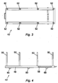
- the dissolvable receptacle 44 is supported by a metal support frame 42, which may be of stainless steel (see Figs.2 to 4 and 8 ).
- the frame 42 includes a base 46, which is a rectangular planar member that comprises a stainless steel mesh.
- the mesh has holes of around 5mm in diameter.
- the base 46 has a rim 48 on its two longitudinal sides and at one end.
- the rim 48 has a dimension of approximately 20-40mm.
- Eight posts 50 are attachable to the base 46, four of the posts 50 being located along each longitudinal side rim 48, at approximately equally spaced intervals.
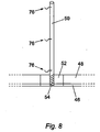
- the posts 50 are removable from the base 46 and engage in welded female push fittings 52, which are built into the rims 48 (see Figs 3 and 8 ),
- the lower ends of the posts 50 are formed with respective corrresponding male push fittings 54, e.g. bevelled push fittings.
- the female and male push fittings 52, 54 can be replaced by a screw-threaded connection,
- the frame 42 includes a head retaining means, which comprises a head strap 56 which engages in two slots 58.
- a head retaining means which comprises a head strap 56 which engages in two slots 58.
- One slot 58 is provided in the rim 48 on each opposite longitudinal side of the frame 42.
- the slots 58 extend all the way through the rims 48, in a plane parallel to the plane of the base 42.
- the head strap 56 can be moved along the length of the slots 58, to suit cadavers of different heights. In this way, the location of the head retaining means is adjustable along the longitudinal axis of the coffin.
- Low friction feet in the form of six stainless steel castors (wheels) 60 are provided on the underneath side of the base 42. These allow the frame 42 to be easily rolled on a surface.
- the dissolvable receptacle 44 comprises a bag 62.
- the bag 62 is generally box shaped (cuboid), and sized to be slightly smaller than the frame 42, when held under light tension.
- the bag 62 has two longitudinal side panels 64, two end panels 66, a base panel 68 and a top panel 70, each of wich are rectangular, to form the cuboid shape.
- the top panel 70 is formed from two halves, split longitudinally each of the halves being attached to its nearest side panel 64.
- the two halves of the top panel 70 are connectable by a zip 72.
- the zip 72 can be closed to tension the top panel 70 or opened to allow a cadaver inside the bag 62 to be viewed.
- Other fastening means may be used instead of a zip, for example hook and loop fasteners, and the fasteners may be positioned to the side rather than in the centre of the top panel 70.
- the dissolvable receptacle 44 is formed from silk.
- the dissolvable receptacle 44 may comprise (alternatively or additionally) wool or a dissolvable starch based blopolymer.
- the dissolvable receptacle can be made from any suitable material which is dissolvable in an alkaline hydrolysis process.
- the coffin also includes a waterpoof liner 74 that is adapted to fit within the bag 62, and which is sewn into the inside of the bag 62. As shown in Fig 7 , the waterproof liner 74 is sewn into the lower part of the bag 62, and fits quite snugly in the base of the bag 62.
- the waterproof liner 74 prevents body fluids from leaking out of the receptacle 44.
- the waterproof liner 74 can comprise an open bag (to allow viewing of the cadaver), or a fully-sealable, closes, bag, Embodiments comprising a closed bag can be used for cadavers which have an infectious disease.
- the waterproof liner 74 comprises a starch based biopolymer material
- the dissolvable receptacle 44 is inherently waterproof (e.g. if the receptacle 44 is made from a dissolvable starch based biopolymer), and a separate waterproof liner 74 is not required
- the receptacle 44 can be attached to the frame 42 by means of hooks 76 provided on the posts 50 of the frame 42, which engage with corresponding silk loops 78 provided on the longitudinal side panels 64 of the bag 62.
- the hooks 76 and the loops 78 comprise attachment means of the receptacle 44 and the frame 42.
- Each post 50 is provided with three hooks 76, one at the top, the middle and the bottom end of the post 50.
- the coffin is provided with an outer casing (not shown), which resembles a conventional, wooden coffin, for presentation to the pubic.
- the outer casing comprises a plurality of wooden panels sized to at least partially surround the coffin.
- a coffin assembly (the coffin and the frame) is created, with the posts 50 being located in the female push fittings 52 of the frame 42.
- the dissolvale receptacle 44 (and integral waterproof liner 74) is placed into the assembled frame 42, and the loops 78 are located over the hooks 76, so that the dissolvable receptacle 44 is supported by the frame. 42.
- the waterproof liner 74 can be positioned in the receptacle 44 and optionally secured thereto.
- the coffin assembly is rigid, so it can be easily handled by the crematorium operators.
- the outer casing is now placed around the coffin assembly (or the coffin assembly is placed inside the outer casing).
- the zip 72 is unzipped and a cadaver is placed in the receptacle 44.
- the cadaver is ready for presentation at the funeral ceremony (if required), with the zip 72 optionally bein left open so that the cadaver can be viewed at the ceremony.
- the mourners see the outer casing, which resembles a conventional coffin, and the cadaver lying inside a silk living of the coffin assembly.
- the cadaver is fully hidden from view. and the shape of the cadaver is not shown (in contrast to a shroud).
- a fully sealed waterproof liner 74 could be used instead of an open waterproof liner 74, in which case the cadaver is also hidden from view.
- the coffin disappears from public view and can be now prepared for the alkaline hydrolysis process.
- the ends of the outer casing are folded down, and the coffin assembly is removed from the outer casing.
- the outer casing can now that packed down, and can be sent back to the funeral directors, optionally with a frame 42 from the previous alkaline hydrolysis process.
- the head strap 56 is now secured to fix the head of the cadaver to the metal frame 42.
- the door 14 of the pressure vessel 12 is opened, and the coffin assembly can now be rolled, using the castors 60, into the chamber 24 of the alkaline hydrolysis unit 10.
- the coffin assembly can either be located in the basket 36, of the coffin assembly can be used instead of the basket 36.
- the door 14 is now locked.
- the integral load cells weigh the cadaver, and the control system calculates, based on the weight, the chemical/water mix concentration that will be optimum for that particular cadaver.
- the aim is to achieve a starting concentration of around 1-1.5 Molar (pH 12-14) Hydroxide solution. (Alternatively, the weighing and the calculations may be done manually).
- Chemicals and water are then added into the chamber 24 in that concentration, via the chemical inlet 40 and the water inlet 30 and spray bar 26, until the chamber 24 is slightly more than half full.
- the chemical used is potassium hydroxide, but alternatively, sodium hydroxide could be used. Potassium hydroxide is preferred because it is more eco-friendly.
- Steam from a steam generator is now passed through the heating/cooling tube 34, Alternatively, or additionally, steam can be directly injected into the chamber 24.
- the chemical/water mix in the chamber 24 is heated by the steam to a temperature of 150-180 degrees centigrade, and the pressure in the chamber 24 rises to 3-10 bar gauge.
- this temperature After the temperature has risen the required amount, this temperature is maintained for a certain "holding" time, to enable the chemicals to act on the cadaver to decompose the cadaver.
- the recirculation pump 38 is used to rapidly recirculate the fluids inside the chamber 24. This ensures a consistently homogeneous solution.
- the jets that are fluidly connected to the recirculation pump aim the recirculated fluid at the head of the cadaver. This helps to provide good chemical availability at the brain tissue area, which is important to ensure that the brain tissue fully decomposes.
- the jets project into the chamber 24 and the outlet ports thereof may be positioned in close proximity to the head of the cadaver.
- the head strap 56 stops the head from floating around the chamber 24, if it breaks off from the neck. This ensures delivery of the chemicals forcefully and directly to the head.
- the cadaver After the required holding time (which may be 2-3 hours), the cadaver should have been fully decomposed.
- the alkaline hydrolysis process can be explained with reference to the natural process of decomposition of cadavers. In alkaline soil, a shallow burial of a body with oxygen available would result in a slow decomposition of tissues via alkaline hydrolysis and expedited by bacteria.
- the cadaver decomposes in an alkaline solution, similar to how it would decompose in nature, but more quickly. Specifically, the cadaver is "resolved” into its constituent elements. Principally, the cadaver is broken down into calcium phosphate bone and teeth remains (hereinafter referred to as "bone Shadows"); and organic material in fluid form.
- the receptacle 44 and the waterproof liner 74 have been fully decomposed, along with the cadaver and any clothing.
- the metal frame 42 has not decomposed, because the metal chosen for the frame 42 is not dissolvable. Hence, what is now left in the chamber 24 is (a) the metal frame 42, (b) bone shadows lying on the base 46 of the frame 42, and (c) a homogeneous waste fluid including the organic material from the cadaver, and any dissolved remains of the receptacle 44, the waterproof liner 74 and any clothing worn by the cadaver
- cooling water is now passed through the heating/cooling tube 34, to cool the waste fluid down to a temperature at which it can be accepted by the local drainage system.
- the "cooling" water used to cool the chamber 34 becomes hot. Some of this hot water can be collected, for later use (see below).
- the waste fluid in the chamber 24 reaches the desired lower temperature, it leaves the chamber 24 via drain 32, and can be dumped into the local drainage system, or an effluent tank, as required.
- the waste fluid leaving the chamber 24 is delivered into a flash dump cooling tank. This reduces the amount of time the waste fluid has to spend in the chamber 24, being cooled, which speeds up the cycle time. i.e. the alkaline hydrolysis unit 10 will be ready quicker for the next cadaver.
- the bone shadows are removed from the chamber 24 via the door 14 (note, there is no rim 48 on the end of the frame 42 nearest the door 14, which facilitates the removal of the bone shadows).
- the collected hot water (formerly the cooling water) can now be used to hot rinse the bone shadows.
- Some surfactant detergent can also be added, to wash residual fatty deposits from the bone shadows.
- the bone shadows are then dried and crushed, and can be presented to the relatives (as is done with the ashes, after a cremation).
- the frame 42 is now removed from the chamber 24.
- the posts 50 can be removed from the base 46 of the frame 42, to enable easy and light transportation of the frame 42 back to the funeral directors, together with the flat packed outer casing for the next coffin to be processed.
- FIG. 9 One embodiment of an overall system used in the alkaline hydrolysis process can be seen in Fig 9, Fig 9 will now be used to explain in more detail some aspects of the alkaline hydrolysis process described above.
- the alkaline hydrolysis unit 10 of Fig 1 is shown in the centre. To the left hand side, is shown a store of potassium hydroxide 80, to be added to the chamber 12 via chemical inlet 40.
- a steam generator 82 which has conduits 82a, 82b that are fluidly connectable to the heating/cooling tube 34.
- conduits 82a, 82b that are fluidly connectable to the heating/cooling tube 34.
- a mains water supply 84 is also fluidly connectable to the heating/cooling tube 34, via a water conduit 84a.
- the water conduit 84a is connected to the heating/cooling tube 34, and mains water flows therethrough.
- heat is transferred from the chamber 24 into the water flowing though the heating/cooling tube 34, so that the chamber 24 becomes cooler and the cooling water becomes hot.
- the heated mains water leaves the heating/cooling tube 34 via a further water conduit 84b, which leads into the inlet of an insulated stainless steel hot water tank 86.
- This hot water can now be stored in the tank 86 until the next cadaver is ready to be processed in the alkaline hydrolysis unit 10.
- hot water is fed from the hot water tank 86, via conduit 86a into the water inlet 30 and the spray bar 26.
- the water that is delivered into the chamber 24 on the subsequent cycle is already hot. This saves a lot of energy, as compared to filling the chamber 24 with cold water, and heating this water.
- the feed water already being hot also drastically reduces the heating time of the subsequent cycle. Also as explained above some of the water from the hot water tank 86 can be used to hot rinse the bone shadows.
- a centrifugal pump 87 is located in the conduit 86a, to pump the water back to the water inlet 30.
- the pump 87 enables rapid refilling send powerful rinsing.
- an underground effluent tank 90 At the bottom of Fig 9 is shown an underground effluent tank 90. At the end of the process, once the waste fluids have been sufficiently cooled, a conduit 90a takes the waste fluids from the outlet 32 to the effluent tank 90. Optionally, the rinse water can be diverted to a sewer.
- Waste fluids could optionally then be taken offsite, in a tanker 9.2, for conversion to a soil improver,
- Fig 10 shows an alternative embodiment of the overall system of Fig 9 . This system is very similar to that shown in Fig 9 . and like parts are designated with like reference number.
- the steam generator 82 and process of heating the chamber 24 is exactly the same as in Fig 9 . However, the process of cooling the chamber 24 is different.
- Fig 10 water from the mains supply 84 is delivered directly into an insulated stainless steel hot water tank 94 via the conduit 84a.
- the hot water tank 94 comprises a steel coil heat exchanger 96.
- the heat exchanger 96 includes a main chamber 96c (into which the mains water is delivered) and a steel conduit 96t located within the main chamber 96c.
- the steel conduit 96t is formed into a coil.
- the drain 32 of the pressure vessel 12 is fluidly connected via conduit 98a to an inlet of the steel conduit 96t.
- An optional branch conduit 98b of the conduit 98a can take rinse water directly to a sewer.
- the waste fluids do not necessarily have to be cooled (or at least, not cooled to such a great extent) in the pressure vessel 12, because they are drained out through conduit 98a, and into the steel conduit 96t.
- the hot waste fluids transfer heat through the walls of the conduit 96t to the mains water stored in the chamber 96c. In this process, the waste fluids become cooled, and the mains water is heated.
- the outlet of the conduit 96t is connected via a conduit 100 to a flash tank 102, in which pressure is relieved and the waste fluids are cooled further.
- the outlet of the flash tan 102 is connected via a conduit 102a to the underground effluent tank 90.
- the waste fluids can then be taken offsite (as descibed with reference to Fig 9 ) or they can be taken (e,g. by a tractor 104) to be used onsite as a soil improver.
- the waste fluids in Fig 9 could also be used onsite as a soil improver.
- the volume of each of the hot water tanks 86, 94 is around 1,500 litres.
- the effluent tank 90 can be plastic (e,g, MDPE) and located underground to allow drainage of the waste fluids to the effluent tank 90 under gravity.
- MDPE plastic
- Preferred embodiments of the invention enable a cycle time of only 2 to 2.5 hours of the cadaver being in the alkaline hydrolyse unit 10.
- Figs 11a, 11b and 11c show an alternative support frame in the form of a bone retaining tray 110.
- the bone retaining tray 110 is an alternative to the basket 36 shown in Fig 1 .
- the bone retaining tray 110 comprises a coffin-receiving flat tray member 112 and a head-retaining means 114, both of which are typically stainless steel perforated mesh.
- the tray member 112 has approximately the same length and width as a coffin and is substafially flat, except that its two longitudinal edges are inclined upwards at ground 30 Segrees. These upwardly inclined edges form rails 116, which are provided with Polytetatrafouroethylene (PTFE) runners to allow the tray 110 to be eastly inserted into, and removed from, the alkaline hydrolysis unit 10.
- the rails 116 may be formed integrally with the rest of the flat tray member 112, or may be formed separately and fixed thereto.
- the head-rotaining means 114 is fixed to (or formed Integrally with) the tray member 112 at one end threroof.
- the head-retaining means 114 comprises a tunnel, and has a crown end 118 which receives the crown of the cadaver's head, and a neck end 120, which receives the cadaver's neck.
- the crown end 118 of the tunnel is optionally closed, whilst the neck end 120 is open to receive the head of the cadaver.
- the head-retaining means 114 flares outwardly toward the neck end 120, such that the neck end 120 of the tunnel is wider than the crown end 118.
- the head-retaining means 114 is provided with an aperture 122 in its upper wall.
- the aperture 122 is very close to the neck end 120.
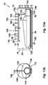
- Figs 12a, 12b and 12c show the bone remaining tray 110 with a bioplastic coffin 130 according to a further aspect of the invention loaded thereon.
- the bioplastic coffin 130 is an alternative coffin to the silk embodiment of Figs 5 to 7 .
- the bioplastic material is a "Mater-BlTM thermoplastic biodegradable polymer". Specifically, the bioplastic material is known as “Mat-Bl TF01 U/095R” and is available from Novamont SpA, Via Fauser, 8 I-28100, Novara, Italy. Its composition is a biodegradeable polyester containing monomers from vegetable oils.
- the bioplastic coffin 130 is fully dissolvable in the alkaline hydrolysis process.
- the bioplastic coffin 130 includes a head end 132 and a feet end 134.
- the bioplastic coffin 130 comprises a substantially rigid container, which surrounds and fully encloses the cadaver.
- the container is injection-moulded.
- the container typically has a base portion and a lid (not shown), for easy insertion of a cadaver.
- the bioplastic coffin 130 is shaped like a sarcophagus, but alternative shapes may also be used. After a fairly flat head portion, the upper profile of the bioplastic coffin 130 (typically on the lid) rises steeply to a peak 136 in the chest area of the cadaver, which then falls away smoothly to the feet and 134.
- Figs 13a and 13b show the bioplastic coffin 130 in place in the alkaline hydrolysis unit 10, supported on the bone retaining tray 110.
- the bone retaining tray 110 and supported bioplastic coffin 130 are locates in the chamber 24, with the head retaining means 114 being positioned in a head-receiving part of the chamber 24.
- the head-receiving part of the chamber 24 is the end that is furthest from the door 14,
- the "head-receiving part" of the chamber 24 means the general area of the chamber 24 which receives the head.
- the alkaline hydrolysis unit 10 has already been described with reference to Fig 1 , but some additional details are shown in Figs 13a and 13b .
- a recirculation jet 138 which is fluidly connected to the recirculation pump 38 (shown in Fig 1 ) by means of a conduit 139.
- the recirculation jet 138 enters the chamber 24 from its top, and extends downwards as far as the top of the head retaining means 114.
- the position of the recirculation jet 138 and the position of the aperture 122 in the head retaining means 114 are selected so that, when the bioplastic coffin 130 is correctly positioned in the chamber 24, the recirculation jet 138 is aligned with the aperture 122.
- the tip of the recirculation jet 138 lies at, or very close to, the aperture 122.
- the purpose of the aperture 122 is to prevent interference of the head retaining means 114 with the recirculation jet 138.
- the bioplastic coffin 130 has a profile shaped to co-operate with the inner profile of the chamber 24 when the bioplastic coffin 130 is inserted in one orientation (head first), and shaped not to co-operate with the inner profile of the chamber 24 when the bioplastic coffin 130 is inserted in the opposite orientation (feet first), such that the coffin 130 can only fit into the chamber 24 when in its correct orientation.
- the recirculation jet 138 forms part of the co-operating inner profile of the chamber 24.
- a drain conduit 140 connected to the drain 32 and which can also be a recirculation suction conduit; and a recirculation return conduit 142; both of which are connected to the base of the chamber 24.
- conduits/other equipment are also connected to the top of the chamber 24. Besides the conduit 139 and the water inlet 30 (used to fill and rinse the chamber 24), these include a vacuum breaker 144, a vent 146, a pressure relief valve 148, a pressure transducer 150, a pressure gauge and switch 152, and a vessel thermocouple 154.
- Figs 11 to 13 functions in the same way as explained in respect of Figs 1 to 10 .
- Aiming the recirculated fluid directly at the head of the cadaver via recirculation jet 138 helps to ensure that the head fully decomposes. This can considerably reduce the time needed to dissolve a cadaver.
- the head retaining means 114 retains the head of the cadaver in the head-receiving part of the chamber 24. As shown in Fig 13a , because the aperture 122 is very close to the neck end 120 of the head retaining means 114, the head of the cadaver (or most of the head) lies to the right of the recirculation jet 138 and the aperture 122. If the head of the cadaver were to break off from the neck, the head is restrained from floating vertically upwards, and from moving laterally, due to the head retaining means 114 (see Fig 13b ). Floatation is the most likely type of movement to occur.
- the head cannot move longitudinally to the left in Fig 13a (towards the feet end of the chamber) due to the recirculated fluids from the jet 138 impacting in what was the neck area of the cadaver, thereby urging the head of the cadaver to the light.
- the head cannot move to the right due to abutment against either the crown end 118 of the tunnel (if closed) or the wall of the chamber 24.
- FIG 14 An alternative embodiment of a bioplastic coffin 160 is shown in Fig 14 , located on the tray 110.
- the bioplastic coffin 160 comprises a flexible bag, instead of a substantially rigid container.
- the flexible bag has a thickness of approximately 100 microns.
- the material of the bioplastic coffin 160 is a "Mater-BiTM thermoplastic biodegradable polymer". Specifically, the composition comprises starch, polyesters and plasticizers. This bioplastic material is available from Novamont SpA, Via Fauser, 8 I-28100, Novara, Italy.
- the bioplastic coffin 160 is fully dissolvable in the alkaline hydrolysis process.
- the bioplastic coffin 160 includes a head end 162 and a feet end 164,
- the tray 110 and flexible bioplastic coffin 160 is inserted into the alkaline hydrolysis unit 10, in the same way as shown in Fig 13 is respect of the non-flexible bioplastic coffin 130.
- the embodiment shown in Fig 14 functions in the same way as explained in respect of Figs 11 to 13 .
- Fig 15 shows the flexible bioplastic coffin 160 of Fig 14 , and also a non-dissolvable plastic mesh receptacle 170 inside the bioplastic coffin 160.
- the mesh is polytetrafluoroethylene (PTFE), but any other non-dissolvable material could alternatively be used.
- the cadaver would be placed within the mesh receptacle 170, which in turn is within the bioplastic coffin 160.
- Fig 15 is a schematic drawing, and in particular the mesh would be much finer than shown, line enough to retain substantially all of the bone residue of the cadaver, after the rest of the cadaver has dissolved, whilst still being course enough to allow the flow of fluids into and out of the mesh receptacle 170.
- the dissolvable receptacle can be made from any material that is decomposable in an alkaline hydrolysis process.
- the coffin assembly does not necessarily need to be a cuboid shape, and could be any shape, although it is preferable if the coffin conceals the shape of the cadaver when closed.
- the coffin is not necessarily closable - e.g. the dissolvable receptacle could be open at its upper surface.
- the frame 42 could optionally have a different form, eg. more or fewer posts, and the base of the frame is not necessarily a mesh.
- the hot water tanks of Figs 9 and 10 are not used, and water from the mains water supply is heated from cold in the alkaline hydrolysis unit 10.
- the means to heat and cool the chamber 12 is not necessarily via heating/cooling tube 34.
- Any suitable heating/cooling means can be used, For example, direct gas injection, or any kind of conduction/convection.
- all waste fluids go directly into the sewer system after cooling (not via any effluent tank/flash tank).
- all waste fluids to into the sewer system via a flash tank, and then into the sewer system (but not via any effluent tank).
- a coffin comprising a dissolvable receptacle is not used, and a cadaver can be placed directly into the basket 36.
- steps relating to the coffin can be omitted, whilst however retaining any or all of the other method/system/apparatus features.
- the aperture 122 is not necessarily in the top surface of the head retaining means 114, and the recirculation jet does not necessarily extend downwards from the top of the alkaline hydrolysis unit 10.
- the aperture 122 may be provided in one of the sides of the tunnel, and the recirulation jet could extend into the chamber of the alkaline hydrolysis unit from one side, instead of from above.
- the mesh recepiacte 170 of Fig 15 is shown inside the bioplastic coffin 160, but could alternatively be located on the outside, around the bioplastic coffin 160. Since the biaplastic coffin 160 will ultimately be dissolved in the process, there is no real difference, as the end result will still be the bone residue retained within the mesh receptacle 170. Further alternatively, the mesh receptacle 170 may be fixed to, or formed integrally With, the bioplastic coffin 160.
- the mesh receptacle 170 is only iflustrated with the flexible bioplastic coffin 160, it could also be used within or outside of any of the other dissolvable receptacles, e.g. the substantially rigid bioplastic coffin 130, or the silk and metal frame embodiment.
- the tunnel-shaped head retaining means 114 of Fig 11 could alternatively be replaced by a head strap.
Abstract
Description
- The present invention relates to the disposal of human remains. In particular, the invention relates to disposal by alkaline hydrolysis. A coffin for use in on alkaline hydrolysis process, an alkaline hydrolysis unit and a method and system for disposing of a cadaver are also described.
- The disposal of human remains after death is currently done by either burial or cremation. Due to a lack of suitable and accessible land and the high costs involved, cremation is becoming preferable to burial However, cremation causes harmtul emissions in the form of dioxins and mercury. Mercury is big problem and in Europa, there is legislation pending to force crematoria to filter abate their emission, This is expensive and also requires very bulky equipment that takes up a lot of room.
- A further problem with cremation is that it uses a lot of gas, and produces large amounts of carbon dioxide, a greenhouse gas , which contributes to global warming. A further disadvantage of cremation is the organic building blocks that make up the body and come from the ecosystem are lost forever during the burning process.
- Some problems with known alkaline hydrolysis methods used for disposal of regulated waste in hospitals, are that the alkaline hydrolysis unit needs to be heated up for each load of waste, and then cooled down, so that the waste fluids produced are cool enough to be received by the local sewer system. This uses a lot of energy, and causes long time intervals between the disposal of successive waste loads. The energy used in heating and cooling is typically wasted, which contributes to global warning.
- When disposing of regulated waste in hospitals, it is known to recirculate fluids within a drecomposition unit by means of a recirculation pump. The hotter the operating tempetalure of the decomposition unit, the faster and more efficiently the decomposition unit can operate. However, in the known processes, the maximum operating temperature of the decompostion unit is limited by the maximum operating temperature that the recirculation pump can tolerate. This is typically only up to 155 degrees Celsius.
- According to a first aspect of the invention there is provided a coffin for use in an alkaline hydrolysis process, the coffin comprising a dissolvable receptacle for a cadaver, the dissolvable receptacle being dissolvable in the alkaline hydrolysis process.
- By "coffin", we mean any receptacle adapted to receive a cadaver. The term "coffin" is not limited to boxes, but can also encompass other cadaver receptacles, such as bags and rigid/flexible containers of non-cuboid shapes, as will be explained.
- Substantially all of the dissolvable receptacle is decomposable in the akaline hydrolysis process, together with the cadaver. Optionally, the coffin is full dissolvable in the alkaline hydrolysis process.
- Optionally, the coffin is provided with an outer casing.
- The outer casing typically resembles a conventional, wooden coffin, for presentation to the public, and is removed prior to the alkaline hydrolysis process. Typically, the outer casing comprises one or more wooden panels sized to at least partially surround the coffin. The panels may be securable to the coffin or to a support frame used with the coffin. Typically, the dissolvable recaptacle comprises one or more of silk, wool, or a bioplastic material.
- Optionally, the entire dissolvable receptacle is bioplaslic.
- Bioplastics are made from organic sources, such as plant starch and sugar cane, instead of from petroleum. Once disposed of, many bioplastics will safely and naturally biodegrade. Most or all bioplastic materials are fully dissolvable by alkaline hydrolysis.
- Advantages of bioplastic, materials include that they may be strong, waterproof, light, simple to manufacture, and inexpensive. Waterproof embodiments do not require an additional waterproof liner. Additionally, the fact that bioplastic materials dissolve with the body makes them environmentally-friendly, since they willl not end up in landtill sites, and they do not require any additional expenditure of energy to destroy.
- Since at the end of the process, the coffin is dissolved together with the cadaver, there is no need to clean and return any parts of the coffin for future use. A bioplastic coffin also allows more rapid emptying and cleaning of the alkaline hydrolysis unit
- Optionally, the bioplastic coffin comprises a substantially rigid container, which may or may not have a lid or cover. A suitable bioplastic material for forming such a container is known as "Mater-Bi TF01 U/095R" and is available from Novamont SpA, Via Fauser, 8 I-28100 Novara, Italy.
- The term "substantially rigid" is to be construed to mean solid in the sense of a box, in contrast to the more cloth-like flexibllity of a bag or fabric. Hence,"substantially rigid" encompasses box-like containers of any shape, made from resilent materials.
- Optionally,the container is injection-moulded. The coffin may be formed in any required shape. For example, the coffin could be formed as a hollow cuboid box, as is conventional. Alternatively, other shapes can be used, for example more closely following the contours of a human body, Optionally, the shape of the coffin may be designed to co-operate with the shape of the alkaline hydrolysis unit in which it will be used. The container may have any desired colour and optionally may be coloured to imitate wood, for aesthetic appeal.
- Alternatively, the coffin may comprise a flexible bag, instead of a substantially rigid container.If a bioplastic material is chosen, the bioplastic material could be a dissolvable starch based biopolymer, such as a "Mater-Bi™ themoplastic biodegradable polymer" that comprises starch, polyesters and plasticizers. This material is available from Novamont SpA, Via Fauser, 8 I-28100. Novara, Italy, Such a bioplastic bag may be formed with very thin walls, whilst still being strong enough to carry a cadaver and still being waterproof. Alternatively, bags of silk or wool or other dissolvable materials could be used.
- Typically, the bag is an open bag, or a closeable bag which can be opened, to allow the cadaver to be viewed.
- Optionally the bag may be closeable (e.g. by a zip) such that the dissolvable receptacle fully surrounds and encloses the cadaver. The zip also provides the tension required to form a "tent" type design that fully hides that cadaver
- Optionally, the coffin also includes a waterproof liner that is adapted to fit within or around the dissolvable, receptacle.
- The waterproof linger prevents body fluids from leaking out of the dissolvable receptacle.
- The waterproof liner can comprise an open bag (to allow viewing of the cadaver), or a fully sealable, closed, bag. Embodiments comprising a closed bag can be used for cadavers which have an infectious disease.
- Typically, the waterproof liner comprises a dissolvable starch based biopolymer material, for example a "Mater-BI™ thermoplastic biodegradable polymer comprising starch, polyesters and plasticizers.
- The waterproof liner is typically sewn or otherwise attached to the dissolvable receptacle.
- In alternative embodiments, the dissolvable receptacle is inherently waterproof (e.g, if the dissolvable receptacle is made from a bioplastic material), and a separate waterproof liner is not required.
- Optionally, the coffin also includes a non-dissolvable mesh receptacle, which will still be intact at the end of the procedure. The mesh receptacle typically comprise a plastic mesh. The mesh receptacle typically comprises a bag. The mesh does not impede the flow of chemicals to the cadaver, which flow freely through the gaps in the mesh.
- Preferably, the mesh of the non-dissolvable mesh receptacle is line enough to retain substantially all of the bone residue of the cadaver (e.g, bone fragments, any body implants) within the non-dissolvable mesh receptacle. This allows the alkaline hydrolysis unit to be emptied and cleaned more rapidly, because the non-dissolvable mesh receptacle can simply be pulled out at the end, instead of having to pick up the bone residue scattered throughout the chamber of the hydrolysis unit.
- The non-dissovable mesh receptacle can be used with any coffin of the invention, whether silk or bioplastic, rigid or flexible.
- The non-dissolvable mesh receptacle could be heated inside of outside of the dissolvable receptacle.
- The non-dissolvable mesh receptacle may be separate to the dissolvable receptacle.
- Alternatively, the non-dissolvable mesh receptacle could be fixed to the dissolvable receptacle by any suitable means (e.g. lamination, bonding, adhesion, stitching, stapling).
- Alternatively, the non-dissolvable mesh receptacle could be formed integrally with the dissolvable receptacle.
- In all embodiments, the dissolvable receptacle will be dissolved in the alkaline hydrolysis process, leaving the non-dissolvable mesh receptacle retaining the bone residue.
- According to a second aspect of the invention there is provided coffin assembly comprising;
- a coffin as claimed in any preceding claim; and
- a support frame for supporting the coffin.
- The support frame can provide the required rigidity for any flexible bag embodiments, and allows the coffin to be handled easily, The metal is chosen so as to be not decomposable in the alkaline hydrolysis unit, so the support frame can be re-used. Typically, the support frame is mental, for example, stainless steel.
- Optionally, the coffin assembly also includes a head retaining means.
- Preferably, the head retaining means is adapted to restrain vertical movement of a head of a cadaver.
- Optionally, the head retaining means is adapted to restrain movement of a head of a cadaver in all directions.
- Typically, the head retaining means comprises part of the support frame.
- Alternatively, the head retaining means comprises a head strap.
- Typically, the location of the head retaining means along the longitudinal axis of the coffin is adjustable, to suit cadavers of different heights. Optionally, the support frame has elongate slots, which secure the head strap to the frame and along which the head strap can be moved to adjust the longitudinal location of the head strap.
- Preferably, the support frame comprises a stainless steel mesh.
- Optionally, the support frame comprises a base and a plurality of posts that are attachable to the base.
- Preferably, the base includes low friction feet.
- Preferably, the low friction feet comprise wheels, rollers, runners or bearings, which allow the frame two be easily rolled or slid on a surface.
- Preferably, the posts are removable from the base (e.g. by screw thread attachments).
- Optionally, each post includes attachment means adapted to attach to corresponding attachment means provided on the dissolvable receptacle. Typically, the attachment means comprises at least one hook provided on each post, and an equal number of loops, each provided at a respective corresponding location on the dissolvable receptale. Alternatively, the hooks could be provided on the dissolvable receptacle, and the loops on the posts. Further alternatively, entirely different attachment means could be provided, e.g. a hook and loop-type fastener (e.g. Velcro™) or a 3M™ Dual Lock™ fastening system.
- Optionally, the base is generally rectangular and is provided with a rim on its two longitudinal sides. Optionally, the rim is also provided along one end.
- According to a third aspect of the invention, there is provided a method of disposing of a cadaver, the method including the steps of:
- placing the cadaver into a coffin comprising a disolvable receptacle;
- placing the coffin in an alkaline hydrolysis unit; and
- adding water and a chemical into the alkaline hydrolysis unit with the cadaver, to break down the cadaver into a fluid component and a bone residue component and to dissolve the dissolvable receptacle of the coffin by alkaline hydrolysis.
- Preferably, the chemical comprises potassium hydroxide, Alternatively, the chemical comprises sodium hydroxide.
- Optionally, the coffin may include any of the features (optional or otherwise) of the first aspect of the invention.
- Preferably, the method includes heating the inside of the alkaline hydrolysis unit, conserving at least some of the heat created, and using this heat to heat the alkaline hydrolysis unit when used for a subsequent cadaver.
- Typically, the heat is conserved by transferring a heated fluid to an insulated heat tank.
- Optionally, the heated fluid comprises water that has been used to cool the alkine hydrolyris unit. Typically, this heated water is added into the alkaline hydrolysis unit when used for the next cadaver.
- Alternatively, the heated fluid comprises waste fluid from the alkaline hydrolysis process. Typically, this heated waste fluid is used to heat mains water in the insulated tank, which will be added into the alkine hydrolysis unit when used for the next cadaver.
- According to a fourth aspect of the invention, there is provided an alkaline hydrolysis unit comprising:
- a chamber for receiving a cadaver to be chemically decomposed by alkaline hydrolysis:
- a mixing system adapted to recirculate fluids within the chamber;
- Typically, the mixing system comprises a recirculation pump fluidly connected to the chamber of the alkaline hydrolysis unit. Typically, the recirculation pump comprises a seal-less stainless steel recirculating pump. The recirculation pump may be a magnetic drive recirculation pump.
- Alternatively, the mixing system comprises a high temperature impeller mixing system.
- According to a fifth aspect of the invention there is provided an alkaline hydrolysis unit comprising:
- a chamber for receiving a cadaver to be chemically decomposed, the chamber including a head-receiving part, intended to receive the head of the cadaver;
- a recirculation pump fluidly connected to the chamber of the alkaline hydrolysis unit and adapted to recirculate fluids within the chamber;
- a head retaining means locatable in the chamber, for retaining the head of the cadaver in the head-receiving part of the chamber, and
- at least one recirculation jet fluidly connected to the recirculation pump and positioned to aim fluid from the recirculation pump at the head-receiving part of the chamber.
- Aiming the recirculated fluid at the head of the cadaver helps to ensure that the head fully decomposes. The skull is very good at protecting the brain tissue from chemical attack, and there are only a few entry places from which the chemicals can penetrate, e.g. the nose and the eye sockets. Aiming the fluid directly at the head can considerably reduce the time needed to dissolve a cadaver, e.g. from 7-8 hours to 2-3 hours.
- The head retaining means prevents the head from floating on the surface of the fluids in the chamber, should the head become detached from the rest of the cadaver.
- The jet may optionally project into the chamber, in close proximity to the the head-receiving part of the chamber.
- Optionally, the alkaline hydrolysis unit includes a support frame, and the head retaining means comprises part of the support frame. Optionally, the head retaining means comprises a tunnel, adapted to at least partially surround a head of a cadaver. Optionally, the head-receiving part of the chamber is bounded by an underside of the tunnel, the recirculation Jet and an end of the chamber. Optionally, the tunnel includes an aperture in a wall thereof which, when the support frame is correctly positioned in the chamber, is aligned with the recirculation jet.
- Alternatively, the head retaining means comprises a strap.
- Preferably, the head retaining means is adapted to restrain vertical movement of a heed of a cadaver in the chamber. Optionally, the head retaining means is adapted to restrain movement of a head of a cadaver in all directions.
- Optionally, the location of the head retaining means is adjustable relative to the longitudinal axis of the chamber.
- Optionally, the alkaline hydrolysis unit is adapted for use with a coffin, insertable within the chamber, and which has a profile shaped to co-operate with the inner profile of the chamber when the coffin is inserted in a correct orientation (e.g. head first), and shaped not to co-operate with the inner profile of the chamber when the coffin is inserted in the opposite. Incorrect orientation (e.g. feet first), thereby preventing entry of the coffin into the chamber in the incorrect orientation. Optionally, the recirculation jet may form part of the co-operating inner profile of the chamber.
- According to a sixth aspect of the invention, there is provided a system for disposing of a cadaver, the system comprising:
- an alkaline hydrolysis unit
- an insulated water tank; and
- a heat exchange means for heating water stored in the insulated water tank using heat from the alkaline hydrolysis unit
- Typically, the heat exchange means includes a conduit for conveying water through a body of fluid in the alkaline hydrolysis unit, or for conveying fluid from the alkaline hydrolysis unit through a body of water.
- Optionally, the heat exchange takes place in the alkaline hydrolysis unit, e.g. the heat exchange means can comprise a healing/cooling tube located within the alkaline hydrolysis unit. In such embodiments, heated water from the heating/cooling tube can be conveyed through a conduct into the insulated tank. The heated water can be stored in the insulated tanK until the alkaline hydrolysis unit has received the next cadaver, at which point the heated water can be conveyed from the insulated tank back into the alkaline hydrolysis unit.
- Alternatively, the heat exchange takes place in the insulated tank. For example, the insulated tank can comprise a heat exchanger.
- In such cases, the heat exchange means typically comprises a steel coil heat exchanger, which includes a chamber and a steel conduit (e.g. a coil) located within the chamber.
- In such embodiments, mains water can be provided in the chamber, and hot waste fluids from the alkaline hydrolysis unit can be conveyed through the steel conduit. The hot waste fluids heat the water in the chamber as the pass through the steel conduit. The heated mains water is stored in the insulated tank, and when the alkaline hydrolysis unit has received the next cadaver, the heated water can be conveyed from the insulated tank back into the alkaline hydrolysis unit.
- Re-filling the alkaline hydrolysis unit with water from the insulated tank that is already hot reduces the energy needed in reheating the alkaline hydrolyisis unit, and reduces the time required to decompose the next cadaver.
- Typically, the system also includes a steam generator, connected to the alkaline hydrolysis unit and adapted to heat the alkaline hydrolysis unit.
- Typically, the system also includes a chemical storage unit which is optionally connectable to the alkaline hydrolysis unit.
- Optionally, the system also includes a flash tank, into which waste fluids from the alkaline hydrolysis unit are conveyed, prior to disposal. According to a seventh aspect of the invention, there is provided a method of disposing of a cadaver, the method including the steps of:
- placing the cadaver in an alkaline hydrolysis unit;
- adding water and a chemical into the alkaline hydrolysis unit with the cadaver and heating the inside of the alkaline hydrolysis unit, to break down the cadaver by an alkaline hydrolysis process into a fluid component and a bone residue component;
- conserving at least some of the heat coated; and
- using this heat to heat the alkaline hydrolysis unit when used for a subsequent cadaver.
- Preferably, the chemical comprises potassium hydroxide. Alternatively, the chemical comprises sodium hydroxide.
- Typically, the heat is conserved by transferring a heated fluid to an insulated heat tank.
- Optionally, the heated fluid comprises water that has been used to cool the alkaline hydrolysis unit. Typically, this heated water is added into the alkaline hydrolysis unit when used for the next cadaver.
- Aternatively, the heated fluid comprises waste fluid from the alkaline hydrolysis process. Typically, this heated waste fluid is used to heat mains water, which will be added into the alkaline hydrolysis unit when used for the next cadaver.
- According to an eighth aspect of the present invention, there is provided a method of disposing of a cadaver, the method including the steps of:
- connecting a recirculation pump to a chamber of an alkaline hydrolysis unit;
- connecting a recirculation jet to the recirculation pump, and aiming the recirculation jet at a head-receiving part of the chamber,
- placing the cadaver into the chamber so that the head of the cadaver is located in the head-receiving part of the chamber and the recirculation jet is aimed at the head;
- using a head retaining means to retain the head of the cadaver in the head-receiving part of the chamber;
- filling the chamber with a mixture of a chemical and water; and
- activating the recirculation pump to aim recirculated fluid, via the recirculation jet, at the head of the cadaver, thereby breaking down the cadaver into a fluid component and a bone residue component by alkaline hydrolysis.
- Optionally, the head retaining means is part of a support frame, and wherein the method includes the step of inserting the head of the cadaver into that part of the support frame.
- Alternatively, the head retaining means comprises a strap that is attachable to a support frame, and wherein the method includes the step of using the strap to fix the head of the cadaver to the support frame.
- Optionally, the method includes the steps of:
- heating the inside of the alkaline hydrolysis unit;
- conserving at least some of the heat created, and
- using this heat to heat the alkaline hydrolysis unit when used for a subsequent cadaver.
- An embodiment of the invention will now be described, by way of example only, and with reference to the following drawings, in which-
-
Fig 1 shows a schematic diagram of an alkaline hydrolysis unit of the invention. -
Fig 2 shows a perspective view of a metal frame used with a coffin according to one embodiment of the invention; -
Fig 3 shows a plan view of the base of theFig 2 frame; -
Fig 4 shows a side view of theFig 2 frame; -
Fig 5 shows a perspective view of a dissolvable receptacle of the coffin; -
Fig 6 shows a detail A ofFig 5 and in particular shows the attachment of the dissolvable receptacle to the metal frame; -
Fig 7 shows a sectional view of the dissolvable receptacle, taken along the line X-X inFig 5 ; -
Fig 8 shows an enlarged view of a post of theFig 2 frame, engaged in a receptacle in the base of the frame; -
Fig 9 show a schematic diagram of a first overall system for deposing of human remains using an alkaline hydrolysis process; -
Fig 10 shows a schematic diagram of a second overall system for disposing of human remains using an alkaline hydrolysis process; -
Figs 11a, 11b and 11c show plan, side and end views respectively of a bone retaining tray; -
Figs 12a, 12b and 12c show plan, side and end views respectively of the bone retaining tray ofFigs 11a, 11b and 11c , and a coffin of another embodiment of the invention loaded on the tray; -
Figs 13a and 13b show sectional views of the alkaline hydrolysis unit ofFig 1 , with the coffin and bone retaining tray ofFigs 12a, 12b and 12c therein; -
Fig 14 shows a side view of the bone retaining tray ofFigs 11a, 11b and 11c and a coffin of a further embodiment of the invention loaded on the tray; and -
Fig 15 is a schematic drawing and shows the coffin ofFig 14 , with a non-dissolvable mesh receptacle located inside the coffin. - Referring now to
Fig 1 , this shows analkaline hydrolysis unit 10 comprising a stainlesssteel pressure vessel 12. Thepressure vessel 12 is a 304L/316L vessel and is rated to achieve up to 180 degrees centigrade working temperature. Thepressure vessel 12 has astainless steel door 14 with ahandle 16. Thedoor 14 can be manually latched or have an automated (hydraulic) latching alternative. Thealkaline hydrolysis unit 10 is clad in 304 stainless steel shroud on all sides with easy removable panels (not shown). - The
pressure vessel 12 is skid mounted, i.e. thepressure vessel 12 haslegs 18 and askid 20. Thelegs 18 are provided with liftingbrackets 22. - The pressure vessel is hollow and defines a
chamber 24 within thepressure vessel 12, inside thechamber 24 is aspray bar 26, which is mounted in an upper part of thechamber 24. Thespray bar 26 is elongate and hasnozzles 28 distributed along its length. Thespray bar 26 has awater inlet 30. - At the bottom of the
chamber 24, at the end of thechamber 24 farthest from thedoor 14, is adrain 32 in the form of an aperture in thechamber 24. Thedrain 32 is attached to an outlet conduit (shown schematically by an arrow). The location of the drain far away from thedoor 14 enables easy rinsing. - Also in the
chamber 24 is a hollow heating/cooling tube 34, As will be explained with reference toFigs 9 and10 , the heating/cooling tube 34 is attached at both ends to a conduit system. Either hot water, hot steam, or cold water can be passed through the heating/cooling tube 34, to regulate the temperature of thechamber 24, as required, - Optionally, the
chamber 24 includes astainless steel basket 36, sized to contain a cadaver. The sides and, base of thebasket 36 are formed from a steel mesh. One end of thebasket 36 has a hinged end to allow folding down. Thebasket 36 typically has PTFE slide strips on both sides to enable easy transfer of thebasket 36 into thechamber 24. - Optionally, the cadaver be placed directly in the
basket 36. In alternative embodiments (described with reference toFigs 2. to 8 ), Thebasket 36 is not always required, as these Figures show a coffin that can be directly located inside thechamber 24, without the need for placement within abasket 36. In some other embodiments, the hinged end of thebasket 36 is folded down, and the coffin ofFigs 2 to 8 is rolled into thebasket 36. - Fluidly connected to the
chamber 24 is a seal-less high temperature stainlesssteel recirculating pump 38. Thepump 38 has an operating temperature up to 180 degrees centigrade. Therecirculation pump 38 is adapted to recirculate fluids within thechamber 24. - Also in the
chamber 24, are one or more jets (not shown) fluidly connected to therecirculation pump 38 and positioned to aim fluid from therecirculation pump 38 at the part of thechamber 24 of thealkaline hydrolysis unit 10 intended to receive the head of the cadaver. The jets are positioned so that they aim fluid from different directions. - Optionally, a head retaining means (e.g. a strap) may be provided as a component of the
chamber 24. - The
chamber 24 is provided with integral load cells (not shown), to weigh a cadaver placed in thechamber 24. Thepressure vessel 12 also has a control system (not shown) comprising a touch screen and boxed in stainless steel for wall mounting. The control system includes software for automated weighing of the cadaver and for calculating, based on the weight, the chemical/water mix concentration that will be optimum for that particular cadaver. Thepressure vessel 12 has an integral modern, or other communication means, for remote interrogation. - The
chamber 24 also has achemical inlet 40, by way of which chemicals for the alkaline hydrolysis process can be introduced into thechamber 24. - Referring now to
Figs 5 to 7 , there is shown a coffin for use in an alkaline hydrolysis process. The coffin comprises adissolvable receptacle 44 for receiving a cadaver. Thedissolvable receptacle 44 may be a cloth receptacle. - The
dissolvable receptacle 44 is supported by ametal support frame 42, which may be of stainless steel (seeFigs.2 to 4 and8 ). Theframe 42 includes abase 46, which is a rectangular planar member that comprises a stainless steel mesh. The mesh has holes of around 5mm in diameter. - The
base 46 has arim 48 on its two longitudinal sides and at one end. Therim 48 has a dimension of approximately 20-40mm. Eightposts 50 are attachable to thebase 46, four of theposts 50 being located along eachlongitudinal side rim 48, at approximately equally spaced intervals. Theposts 50 are removable from thebase 46 and engage in weldedfemale push fittings 52, which are built into the rims 48 (seeFigs 3 and8 ), The lower ends of theposts 50 are formed with respective corrrespondingmale push fittings 54, e.g. bevelled push fittings. In alternative embodiments, the female andmale push fittings - The
frame 42 includes a head retaining means, which comprises ahead strap 56 which engages in twoslots 58. Oneslot 58 is provided in therim 48 on each opposite longitudinal side of theframe 42. Theslots 58 extend all the way through therims 48, in a plane parallel to the plane of thebase 42. - The
head strap 56 can be moved along the length of theslots 58, to suit cadavers of different heights. In this way, the location of the head retaining means is adjustable along the longitudinal axis of the coffin. - Low friction feet, in the form of six stainless steel castors (wheels) 60 are provided on the underneath side of the
base 42. These allow theframe 42 to be easily rolled on a surface. - Turning now to
Figs 5 to 7 , thedissolvable receptacle 44 comprises abag 62. Thebag 62 is generally box shaped (cuboid), and sized to be slightly smaller than theframe 42, when held under light tension. Thebag 62 has twolongitudinal side panels 64, twoend panels 66, abase panel 68 and atop panel 70, each of wich are rectangular, to form the cuboid shape. Thetop panel 70 is formed from two halves, split longitudinally each of the halves being attached to itsnearest side panel 64. The two halves of thetop panel 70 are connectable by azip 72. Thezip 72 can be closed to tension thetop panel 70 or opened to allow a cadaver inside thebag 62 to be viewed. Other fastening means may be used instead of a zip, for example hook and loop fasteners, and the fasteners may be positioned to the side rather than in the centre of thetop panel 70. - In this embodiment, the
dissolvable receptacle 44 is formed from silk. In alternative embodiments, thedissolvable receptacle 44 may comprise (alternatively or additionally) wool or a dissolvable starch based blopolymer. Alternatively, the dissolvable receptacle can be made from any suitable material which is dissolvable in an alkaline hydrolysis process. - The coffin also includes a
waterpoof liner 74 that is adapted to fit within thebag 62, and which is sewn into the inside of thebag 62. As shown inFig 7 , thewaterproof liner 74 is sewn into the lower part of thebag 62, and fits quite snugly in the base of thebag 62. - The
waterproof liner 74 prevents body fluids from leaking out of thereceptacle 44. - The
waterproof liner 74 can comprise an open bag (to allow viewing of the cadaver), or a fully-sealable, closes, bag, Embodiments comprising a closed bag can be used for cadavers which have an infectious disease. - The
waterproof liner 74 comprises a starch based biopolymer material - In alternative embodiments, the
dissolvable receptacle 44 is inherently waterproof (e.g. if thereceptacle 44 is made from a dissolvable starch based biopolymer), and a separatewaterproof liner 74 is not required - The
receptacle 44 can be attached to theframe 42 by means ofhooks 76 provided on theposts 50 of theframe 42, which engage with correspondingsilk loops 78 provided on thelongitudinal side panels 64 of thebag 62. - Hence, the
hooks 76 and theloops 78 comprise attachment means of thereceptacle 44 and theframe 42. - Each
post 50 is provided with threehooks 76, one at the top, the middle and the bottom end of thepost 50. - The coffin is provided with an outer casing (not shown), which resembles a conventional, wooden coffin, for presentation to the pubic. The outer casing comprises a plurality of wooden panels sized to at least partially surround the coffin.
- In use, a coffin assembly (the coffin and the frame) is created, with the
posts 50 being located in thefemale push fittings 52 of theframe 42. The dissolvale receptacle 44 (and integral waterproof liner 74) is placed into the assembledframe 42, and theloops 78 are located over thehooks 76, so that thedissolvable receptacle 44 is supported by the frame. 42. (In embodiments where thewaterproof liner 74 is used but is not integral with thereceptacle 44, thewaterproof liner 74 can be positioned in thereceptacle 44 and optionally secured thereto.) - The coffin assembly is rigid, so it can be easily handled by the crematorium operators.
- The outer casing is now placed around the coffin assembly (or the coffin assembly is placed inside the outer casing).
- The
zip 72 is unzipped and a cadaver is placed in thereceptacle 44. - Now, the cadaver is ready for presentation at the funeral ceremony (if required), with the
zip 72 optionally bein left open so that the cadaver can be viewed at the ceremony. The mourners see the outer casing, which resembles a conventional coffin, and the cadaver lying inside a silk living of the coffin assembly. - Alternatively, if the
zip 72 is closed, the cadaver is fully hidden from view. and the shape of the cadaver is not shown (in contrast to a shroud). - Alternatively, if the cadaver has a contagious disease, a fully sealed
waterproof liner 74 could be used instead of an openwaterproof liner 74, in which case the cadaver is also hidden from view. - After the funeral ceremony, the coffin disappears from public view and can be now prepared for the alkaline hydrolysis process. First, the ends of the outer casing are folded down, and the coffin assembly is removed from the outer casing. The outer casing can now that packed down, and can be sent back to the funeral directors, optionally with a
frame 42 from the previous alkaline hydrolysis process. - The
head strap 56 is now secured to fix the head of the cadaver to themetal frame 42. - The
door 14 of thepressure vessel 12 is opened, and the coffin assembly can now be rolled, using thecastors 60, into thechamber 24 of thealkaline hydrolysis unit 10. As described above, the coffin assembly can either be located in thebasket 36, of the coffin assembly can be used instead of thebasket 36. - The
door 14 is now locked. The integral load cells weigh the cadaver, and the control system calculates, based on the weight, the chemical/water mix concentration that will be optimum for that particular cadaver. The aim is to achieve a starting concentration of around 1-1.5 Molar (pH 12-14) Hydroxide solution. (Alternatively, the weighing and the calculations may be done manually). - Chemicals and water are then added into the
chamber 24 in that concentration, via thechemical inlet 40 and thewater inlet 30 andspray bar 26, until thechamber 24 is slightly more than half full. In this example, the chemical used is potassium hydroxide, but alternatively, sodium hydroxide could be used. Potassium hydroxide is preferred because it is more eco-friendly. - Steam from a steam generator is now passed through the heating/
cooling tube 34, Alternatively, or additionally, steam can be directly injected into thechamber 24. The chemical/water mix in thechamber 24 is heated by the steam to a temperature of 150-180 degrees centigrade, and the pressure in thechamber 24 rises to 3-10 bar gauge. - After the temperature has risen the required amount, this temperature is maintained for a certain "holding" time, to enable the chemicals to act on the cadaver to decompose the cadaver.
- During the heating process and the subsequent "holding" time, the
recirculation pump 38 is used to rapidly recirculate the fluids inside thechamber 24. This ensures a consistently homogeneous solution. - The jets that are fluidly connected to the recirculation pump aim the recirculated fluid at the head of the cadaver. This helps to provide good chemical availability at the brain tissue area, which is important to ensure that the brain tissue fully decomposes. Optionally, the jets project into the
chamber 24 and the outlet ports thereof may be positioned in close proximity to the head of the cadaver. Thehead strap 56 stops the head from floating around thechamber 24, if it breaks off from the neck. This ensures delivery of the chemicals forcefully and directly to the head. - After the required holding time (which may be 2-3 hours), the cadaver should have been fully decomposed. The alkaline hydrolysis process can be explained with reference to the natural process of decomposition of cadavers. In alkaline soil, a shallow burial of a body with oxygen available would result in a slow decomposition of tissues via alkaline hydrolysis and expedited by bacteria.
- In the
alkaline hydrolysis unit 10, the cadaver decomposes in an alkaline solution, similar to how it would decompose in nature, but more quickly. Specifically, the cadaver is "resolved" into its constituent elements. Principally, the cadaver is broken down into calcium phosphate bone and teeth remains (hereinafter referred to as "bone Shadows"); and organic material in fluid form. - In the alkaline hydrolysis process, the
receptacle 44 and thewaterproof liner 74 have been fully decomposed, along with the cadaver and any clothing. - The
metal frame 42 has not decomposed, because the metal chosen for theframe 42 is not dissolvable. Hence, what is now left in thechamber 24 is (a) themetal frame 42, (b) bone shadows lying on thebase 46 of theframe 42, and (c) a homogeneous waste fluid including the organic material from the cadaver, and any dissolved remains of thereceptacle 44, thewaterproof liner 74 and any clothing worn by the cadaver - Next, cooling water is now passed through the heating/
cooling tube 34, to cool the waste fluid down to a temperature at which it can be accepted by the local drainage system. - During this process, the "cooling" water used to cool the
chamber 34 becomes hot. Some of this hot water can be collected, for later use (see below). - Once the waste fluid in the
chamber 24 reaches the desired lower temperature, it leaves thechamber 24 viadrain 32, and can be dumped into the local drainage system, or an effluent tank, as required. Optionally, the waste fluid leaving thechamber 24 is delivered into a flash dump cooling tank. This reduces the amount of time the waste fluid has to spend in thechamber 24, being cooled, which speeds up the cycle time. i.e. thealkaline hydrolysis unit 10 will be ready quicker for the next cadaver. - It should be noted that no vacuum is applied to the
pressure vessel 12, and any venting of thechamber 24 is via thedrain 32. - After the waste fluid has been drained, the bone shadows are removed from the
chamber 24 via the door 14 (note, there is norim 48 on the end of theframe 42 nearest thedoor 14, which facilitates the removal of the bone shadows). - The collected hot water (formerly the cooling water) can now be used to hot rinse the bone shadows. Some surfactant detergent can also be added, to wash residual fatty deposits from the bone shadows. The bone shadows are then dried and crushed, and can be presented to the relatives (as is done with the ashes, after a cremation).
- The
frame 42 is now removed from thechamber 24. Theposts 50 can be removed from thebase 46 of theframe 42, to enable easy and light transportation of theframe 42 back to the funeral directors, together with the flat packed outer casing for the next coffin to be processed. - One embodiment of an overall system used in the alkaline hydrolysis process can be seen in
Fig 9, Fig 9 will now be used to explain in more detail some aspects of the alkaline hydrolysis process described above. - The
alkaline hydrolysis unit 10 ofFig 1 is shown in the centre. To the left hand side, is shown a store ofpotassium hydroxide 80, to be added to thechamber 12 viachemical inlet 40. - At the top, is shown a
steam generator 82, which hasconduits cooling tube 34. In this way, in the heating stage, the steam to heat thechamber 12 is generated by thesteam generator 82, flows throughconduit 82a into the heating/cooling tube 34, and is returned to the steam generator viaconduit 82b. - A
mains water supply 84 is also fluidly connectable to the heating/cooling tube 34, via awater conduit 84a. In the cooling stage, thewater conduit 84a is connected to the heating/cooling tube 34, and mains water flows therethrough. In the heating/cooling tube 34, heat is transferred from thechamber 24 into the water flowing though the heating/cooling tube 34, so that thechamber 24 becomes cooler and the cooling water becomes hot. - The heated mains water leaves the heating/
cooling tube 34 via afurther water conduit 84b, which leads into the inlet of an insulated stainless steelhot water tank 86. This hot water can now be stored in thetank 86 until the next cadaver is ready to be processed in thealkaline hydrolysis unit 10. - When the next cadaver is ready to be processed, hot water is fed from the
hot water tank 86, viaconduit 86a into thewater inlet 30 and thespray bar 26. Thus, the water that is delivered into thechamber 24 on the subsequent cycle is already hot. This saves a lot of energy, as compared to filling thechamber 24 with cold water, and heating this water. Furthermore, the feed water already being hot also drastically reduces the heating time of the subsequent cycle. Also as explained above some of the water from thehot water tank 86 can be used to hot rinse the bone shadows. - A
centrifugal pump 87 is located in theconduit 86a, to pump the water back to thewater inlet 30. Thepump 87 enables rapid refilling send powerful rinsing. - At the bottom of
Fig 9 is shown anunderground effluent tank 90. At the end of the process, once the waste fluids have been sufficiently cooled, aconduit 90a takes the waste fluids from theoutlet 32 to theeffluent tank 90. Optionally, the rinse water can be diverted to a sewer. - The Waste fluids could optionally then be taken offsite, in a tanker 9.2, for conversion to a soil improver,
-
Fig 10 shows an alternative embodiment of the overall system ofFig 9 . This system is very similar to that shown inFig 9 . and like parts are designated with like reference number. - The
steam generator 82 and process of heating thechamber 24 is exactly the same as inFig 9 . However, the process of cooling thechamber 24 is different. - In
Fig 10 , water from the mains supply 84 is delivered directly into an insulated stainless steelhot water tank 94 via theconduit 84a. Thehot water tank 94 comprises a steelcoil heat exchanger 96. Theheat exchanger 96 includes amain chamber 96c (into which the mains water is delivered) and asteel conduit 96t located within themain chamber 96c. Thesteel conduit 96t is formed into a coil. - The
drain 32 of thepressure vessel 12 is fluidly connected viaconduit 98a to an inlet of thesteel conduit 96t. Anoptional branch conduit 98b of theconduit 98a can take rinse water directly to a sewer. - In such systems, the waste fluids do not necessarily have to be cooled (or at least, not cooled to such a great extent) in the
pressure vessel 12, because they are drained out throughconduit 98a, and into thesteel conduit 96t. In theconduit 96t, the hot waste fluids transfer heat through the walls of theconduit 96t to the mains water stored in thechamber 96c. In this process, the waste fluids become cooled, and the mains water is heated. - The outlet of the
conduit 96t is connected via aconduit 100 to aflash tank 102, in which pressure is relieved and the waste fluids are cooled further. - The outlet of the
flash tan 102 is connected via aconduit 102a to theunderground effluent tank 90. The waste fluids can then be taken offsite (as descibed with reference toFig 9 ) or they can be taken (e,g. by a tractor 104) to be used onsite as a soil improver. Of course, the waste fluids inFig 9 could also be used onsite as a soil improver. - Turning back to the
hot water tank 94, when the next cadaver in ready to be processed in thealkaline hydrolysis unit 10, water from an outlet of thechamber 96c is fed via aconduit 96a into thewater inlet 30 andspray bar 26 of thealkaline hydrolysis unit 10. Therefore, the water used to fill thechamber 24 is already hot which greatly reduces the energy needed to heat thechamber 24, and the heating time required, as with theFig 9 system. - As an example only, the volume of each of the
hot water tanks - The
effluent tank 90 can be plastic (e,g, MDPE) and located underground to allow drainage of the waste fluids to theeffluent tank 90 under gravity. - Preferred embodiments of the invention enable a cycle time of only 2 to 2.5 hours of the cadaver being in the
alkaline hydrolyse unit 10. -
Figs 11a, 11b and 11c show an alternative support frame in the form of abone retaining tray 110. Thebone retaining tray 110 is an alternative to thebasket 36 shown inFig 1 . - The
bone retaining tray 110 comprises a coffin-receivingflat tray member 112 and a head-retaining means 114, both of which are typically stainless steel perforated mesh. Thetray member 112 has approximately the same length and width as a coffin and is substafially flat, except that its two longitudinal edges are inclined upwards atground 30 Segrees. These upwardly inclined edges form rails 116, which are provided with Polytetatrafouroethylene (PTFE) runners to allow thetray 110 to be eastly inserted into, and removed from, thealkaline hydrolysis unit 10. Therails 116 may be formed integrally with the rest of theflat tray member 112, or may be formed separately and fixed thereto. - The head-rotaining means 114 is fixed to (or formed Integrally with) the
tray member 112 at one end threroof. The head-retaining means 114 comprises a tunnel, and has acrown end 118 which receives the crown of the cadaver's head, and aneck end 120, which receives the cadaver's neck. Thecrown end 118 of the tunnel is optionally closed, whilst theneck end 120 is open to receive the head of the cadaver. The head-retaining means 114 flares outwardly toward theneck end 120, such that theneck end 120 of the tunnel is wider than thecrown end 118. - The head-retaining means 114 is provided with an
aperture 122 in its upper wall. Theaperture 122 is very close to theneck end 120. -
Figs 12a, 12b and 12c show thebone remaining tray 110 with abioplastic coffin 130 according to a further aspect of the invention loaded thereon. - The
bioplastic coffin 130 is an alternative coffin to the silk embodiment ofFigs 5 to 7 . - The bioplastic material is a "Mater-Bl™ thermoplastic biodegradable polymer". Specifically, the bioplastic material is known as "Mat-Bl TF01 U/095R" and is available from Novamont SpA, Via Fauser, 8 I-28100, Novara, Italy. Its composition is a biodegradeable polyester containing monomers from vegetable oils. The
bioplastic coffin 130 is fully dissolvable in the alkaline hydrolysis process. Thebioplastic coffin 130 includes ahead end 132 and afeet end 134. - The
bioplastic coffin 130 comprises a substantially rigid container, which surrounds and fully encloses the cadaver. The container is injection-moulded. The container typically has a base portion and a lid (not shown), for easy insertion of a cadaver. In this embodiment, thebioplastic coffin 130 is shaped like a sarcophagus, but alternative shapes may also be used. After a fairly flat head portion, the upper profile of the bioplastic coffin 130 (typically on the lid) rises steeply to apeak 136 in the chest area of the cadaver, which then falls away smoothly to the feet and 134. -
Figs 13a and 13b show thebioplastic coffin 130 in place in thealkaline hydrolysis unit 10, supported on thebone retaining tray 110. - The
bone retaining tray 110 and supportedbioplastic coffin 130 are locates in thechamber 24, with the head retaining means 114 being positioned in a head-receiving part of thechamber 24. In this embodiment, the head-receiving part of thechamber 24 is the end that is furthest from thedoor 14, The "head-receiving part" of thechamber 24 means the general area of thechamber 24 which receives the head. - The
alkaline hydrolysis unit 10 has already been described with reference toFig 1 , but some additional details are shown inFigs 13a and 13b . These include arecirculation jet 138, which is fluidly connected to the recirculation pump 38 (shown inFig 1 ) by means of aconduit 139. Therecirculation jet 138 enters thechamber 24 from its top, and extends downwards as far as the top of the head retaining means 114. The position of therecirculation jet 138 and the position of theaperture 122 in the head retaining means 114 are selected so that, when thebioplastic coffin 130 is correctly positioned in thechamber 24, therecirculation jet 138 is aligned with theaperture 122. The tip of therecirculation jet 138 lies at, or very close to, theaperture 122. The purpose of theaperture 122 is to prevent interference of the head retaining means 114 with therecirculation jet 138. - Due to the shape of the upper profile of the bioplastic coffin 130 (in particular its varying height), and the distance to which the
recirculation jet 138 extends into thechamber 24, it is not possible to insert thebioplastic coffin 130 into thechamber 24 in the wrong orientation (i.e. feet first). If this were attempted, thebioplastic coffin 130 could not fit into thechamber 24 because the upper profile of thebioplastic coffin 130 would abut against therecirculation jet 138. Also, the feet end 134 of thecoffin 130 would not fit fully within the tunnel of the head retaining means 144, Hence, thebioplastic coffin 130 has a profile shaped to co-operate with the inner profile of thechamber 24 when thebioplastic coffin 130 is inserted in one orientation (head first), and shaped not to co-operate with the inner profile of thechamber 24 when thebioplastic coffin 130 is inserted in the opposite orientation (feet first), such that thecoffin 130 can only fit into thechamber 24 when in its correct orientation. In this embodiment, therecirculation jet 138 forms part of the co-operating inner profile of thechamber 24. - Also shown in
Fig 13a is adrain conduit 140, connected to thedrain 32 and which can also be a recirculation suction conduit; and arecirculation return conduit 142; both of which are connected to the base of thechamber 24. - Various conduits/other equipment are also connected to the top of the
chamber 24. Besides theconduit 139 and the water inlet 30 (used to fill and rinse the chamber 24), these include avacuum breaker 144, avent 146, apressure relief valve 148, apressure transducer 150, a pressure gauge andswitch 152, and avessel thermocouple 154. - In use, the embodiment shown in
Figs 11 to 13 functions in the same way as explained in respect ofFigs 1 to 10 . Aiming the recirculated fluid directly at the head of the cadaver viarecirculation jet 138 helps to ensure that the head fully decomposes. This can considerably reduce the time needed to dissolve a cadaver. - The head retaining means 114 retains the head of the cadaver in the head-receiving part of the
chamber 24. As shown inFig 13a , because theaperture 122 is very close to theneck end 120 of the head retaining means 114, the head of the cadaver (or most of the head) lies to the right of therecirculation jet 138 and theaperture 122. If the head of the cadaver were to break off from the neck, the head is restrained from floating vertically upwards, and from moving laterally, due to the head retaining means 114 (seeFig 13b ). Floatation is the most likely type of movement to occur. However additionally, the head cannot move longitudinally to the left inFig 13a (towards the feet end of the chamber) due to the recirculated fluids from thejet 138 impacting in what was the neck area of the cadaver, thereby urging the head of the cadaver to the light. The head cannot move to the right due to abutment against either thecrown end 118 of the tunnel (if closed) or the wall of thechamber 24. - An alternative embodiment of a
bioplastic coffin 160 is shown inFig 14 , located on thetray 110. Thebioplastic coffin 160 comprises a flexible bag, instead of a substantially rigid container. The flexible bag has a thickness of approximately 100 microns. - The material of the
bioplastic coffin 160 is a "Mater-Bi™ thermoplastic biodegradable polymer". Specifically, the composition comprises starch, polyesters and plasticizers. This bioplastic material is available from Novamont SpA, Via Fauser, 8 I-28100, Novara, Italy. - The
bioplastic coffin 160 is fully dissolvable in the alkaline hydrolysis process. Thebioplastic coffin 160 includes ahead end 162 and afeet end 164, - The
tray 110 andflexible bioplastic coffin 160 is inserted into thealkaline hydrolysis unit 10, in the same way as shown inFig 13 is respect of thenon-flexible bioplastic coffin 130. In use, the embodiment shown inFig 14 functions in the same way as explained in respect ofFigs 11 to 13 . -
Fig 15 shows theflexible bioplastic coffin 160 ofFig 14 , and also a non-dissolvableplastic mesh receptacle 170 inside thebioplastic coffin 160. In this example, the mesh is polytetrafluoroethylene (PTFE), but any other non-dissolvable material could alternatively be used. The cadaver would be placed within themesh receptacle 170, which in turn is within thebioplastic coffin 160.Fig 15 is a schematic drawing, and in particular the mesh would be much finer than shown, line enough to retain substantially all of the bone residue of the cadaver, after the rest of the cadaver has dissolved, whilst still being course enough to allow the flow of fluids into and out of themesh receptacle 170. - Modifications and improvements can be incorporated without departing from the scope of the invention. For example, the dissolvable receptacle can be made from any material that is decomposable in an alkaline hydrolysis process.
- The coffin assembly does not necessarily need to be a cuboid shape, and could be any shape, although it is preferable if the coffin conceals the shape of the cadaver when closed.
- The coffin is not necessarily closable - e.g. the dissolvable receptacle could be open at its upper surface.
- The
frame 42 could optionally have a different form, eg. more or fewer posts, and the base of the frame is not necessarily a mesh. - In some embodiments, the hot water tanks of
Figs 9 and10 are not used, and water from the mains water supply is heated from cold in thealkaline hydrolysis unit 10. - The means to heat and cool the
chamber 12 is not necessarily via heating/cooling tube 34. Any suitable heating/cooling means can be used, For example, direct gas injection, or any kind of conduction/convection. - In some embodiments, all waste fluids go directly into the sewer system after cooling (not via any effluent tank/flash tank).
- In some alternative embodiments, all waste fluids to into the sewer system, via a flash tank, and then into the sewer system (but not via any effluent tank).
- In accordance with the fourth to the eigth aspects of the present invention, it should be noted that the presence of a coffin of the first and second aspects of the invention is not an essential feature in such systems/ apparatus/ methods.
- For example, in some embodiments, a coffin comprising a dissolvable receptacle is not used, and a cadaver can be placed directly into the
basket 36. Hence, in the abovedescribed exemplary method, the steps relating to the coffin can be omitted, whilst however retaining any or all of the other method/system/apparatus features. - Any of the features of the eight aspects of the invention can be incorporated and used with any of the other of the eight aspects of the invention.
- In the embodiment of
Figs 11a, 11b and 11c , theaperture 122 is not necessarily in the top surface of the head retaining means 114, and the recirculation jet does not necessarily extend downwards from the top of thealkaline hydrolysis unit 10. In other embodiments, theaperture 122 may be provided in one of the sides of the tunnel, and the recirulation jet could extend into the chamber of the alkaline hydrolysis unit from one side, instead of from above. - The mesh recepiacte 170 of
Fig 15 is shown inside thebioplastic coffin 160, but could alternatively be located on the outside, around thebioplastic coffin 160. Since thebiaplastic coffin 160 will ultimately be dissolved in the process, there is no real difference, as the end result will still be the bone residue retained within themesh receptacle 170. Further alternatively, themesh receptacle 170 may be fixed to, or formed integrally With, thebioplastic coffin 160. - Although the
mesh receptacle 170 is only iflustrated with theflexible bioplastic coffin 160, it could also be used within or outside of any of the other dissolvable receptacles, e.g. the substantiallyrigid bioplastic coffin 130, or the silk and metal frame embodiment. - The tunnel-shaped head retaining means 114 of
Fig 11 could alternatively be replaced by a head strap.
Claims (15)
- A coffin for use in an alkaline hydrolysis process, the coffin comprising a dissolvable receptacle for a cadaver the dissolvable receptacle being dissolvable in the alkaline hydrolysis process,
- A coffin as claimed in claim 1, wherein the disolvable receptacle comprises at least one of silk, wool, and a bioplastic material.
- A coffin as claimed in claim 2, wherein the coffin comprises a substantially rigid container.
- A coffin as claimed in any preceding claim, wherein the dissovable receptacle comprises a flexible bag,
- As coffin as claimed in claim 4, wherein the bag is closable such that the dissolvable receptacle can fully surround and enclose a cadaver.
- A coffin as claimed in any receding claim, including a waterproof liner adapted to fit within or around the dissolvable receptacle.
- A coffin as claimed in any preceding claim, including a non-dissolvable mesh receptacle,
- A coffin as claimed in claim 7, wherein the mesh of the non-dissolvable mesh receptacle is fine enough to retain substantially all bone residue of a cadaver therein,
- A coffin as claimed in claim 7 or 8, wherien the non-dissolvable mesh receptacle is fixed to the dissolvable receptacle.
- A coffin as claimed in any of claims 7 to 9, wherein the non-dissolvable mesh receptacle is formed integrally with the dissolvable receptacle.
- A coffin assembly comprising:a coffin as claimed in any preceding claim; anda support frame for supporting the coffin.
- A coffin assombly as claimed in claim 14, including a head retaining means adapted to restrain vertical movement of a head of a cadaver.
- A coffin assembly as claimed in claim 12, wherein the head retaining means is adapted to restrain movement of a head of a cadaver in all directions.
- A coffin assembly as claimed in claim 12 or 13, wherein the head retaining means comprises part of the support frame.
- A coffin assembly as claimed in any of claims 12 to 14, wherein the location of the head retaining means along a longitudinal axis of the coffin is adjustable.
Applications Claiming Priority (2)
| Application Number | Priority Date | Filing Date | Title |
|---|---|---|---|
| GB0719482A GB0719482D0 (en) | 2007-10-05 | 2007-10-05 | Disposal of human remains |
| EP20080806716 EP2207632B1 (en) | 2007-10-05 | 2008-10-03 | Disposal of human remains |
Related Parent Applications (1)
| Application Number | Title | Priority Date | Filing Date |
|---|---|---|---|
| EP08806716.0 Division | 2008-10-03 |
Publications (3)
| Publication Number | Publication Date |
|---|---|
| EP2295020A2 true EP2295020A2 (en) | 2011-03-16 |
| EP2295020A3 EP2295020A3 (en) | 2011-03-30 |
| EP2295020B1 EP2295020B1 (en) | 2013-03-13 |
Family
ID=38829682
Family Applications (2)
| Application Number | Title | Priority Date | Filing Date |
|---|---|---|---|
| EP20100195320 Active EP2295020B1 (en) | 2007-10-05 | 2008-10-03 | Disposal of Human Remains |
| EP20080806716 Active EP2207632B1 (en) | 2007-10-05 | 2008-10-03 | Disposal of human remains |
Family Applications After (1)
| Application Number | Title | Priority Date | Filing Date |
|---|---|---|---|
| EP20080806716 Active EP2207632B1 (en) | 2007-10-05 | 2008-10-03 | Disposal of human remains |
Country Status (11)
| Country | Link |
|---|---|
| US (2) | US8931147B2 (en) |
| EP (2) | EP2295020B1 (en) |
| CN (1) | CN102026742B (en) |
| AT (1) | ATE521424T1 (en) |
| AU (2) | AU2008306600B2 (en) |
| CA (2) | CA2729447C (en) |
| ES (2) | ES2371990T3 (en) |
| GB (1) | GB0719482D0 (en) |
| HK (1) | HK1156906A1 (en) |
| PT (2) | PT2207632E (en) |
| WO (2) | WO2009044207A2 (en) |
Families Citing this family (22)
| Publication number | Priority date | Publication date | Assignee | Title |
|---|---|---|---|---|
| GB0719482D0 (en) * | 2007-10-05 | 2007-12-05 | Resomation Ltd | Disposal of human remains |
| FR2967478A1 (en) * | 2010-11-15 | 2012-05-18 | Europ Metal Concept Emc | METHOD AND SYSTEM FOR TREATING RESIDUES RESULTING FROM THE COMBUSTION OF A COFFEE CONTAINING THE BODY OF A PERSON DECEDED |
| CN102069087B (en) * | 2010-12-30 | 2012-10-10 | 青岛欧特尔生物安全技术有限公司 | Fixed safety disposal device for animals with diseases by alkaline degradation |
| US8889403B2 (en) * | 2011-05-12 | 2014-11-18 | Empire Technology Development Llc | Bioreactor for engineered tissue |
| ES1074899Y (en) * | 2011-06-01 | 2011-09-28 | Limbo Disseny S L | BIODEGRADABLE ATTENTION |
| US9168573B2 (en) * | 2012-07-10 | 2015-10-27 | Hamid Hojaji | Products made from biomass and method of making the same |
| US9597249B2 (en) | 2013-06-13 | 2017-03-21 | Krs, Llc | Body containment construction suitable for use within bio-cremation processes |
| US9700477B1 (en) * | 2016-08-10 | 2017-07-11 | Alec John Franks | Water based pet cremation basket apparatus with enhanced strength |
| WO2018045374A1 (en) | 2016-09-02 | 2018-03-08 | Regents Of The University Of Minnesota | Systems and methods for body-proximate recoverable capture of mercury vapor during cremation |
| CN108213033B (en) * | 2017-11-27 | 2020-05-01 | 中国农业科学院农业环境与可持续发展研究所 | Alkaline hydrolysis harmless treatment system and process for animals died of diseases |
| ES2931318T3 (en) * | 2018-07-18 | 2022-12-28 | Verde Products Inc | Decomposition of bodily remains |
| FR3087647B1 (en) * | 2018-10-31 | 2020-10-16 | Mansour Hasnaoui | COFFIN ESPECIALLY FOR BURIAL IN THE GROUND. |
| US11541369B1 (en) * | 2019-01-29 | 2023-01-03 | Philip Jonathon Mason | Rotating tissue digestor system and method of use |
| CN109821862A (en) * | 2019-03-25 | 2019-05-31 | 锐菁源(成都)科技有限公司 | A kind of human body water burial green processing equipment |
| ES1230935Y (en) * | 2019-05-16 | 2020-06-04 | Limbo Disseny S L | BAG FOR THE TRANSFER OF CADAVERES |
| RU2723861C1 (en) * | 2019-10-09 | 2020-06-17 | Игорь Георгиевич Киселев | Plant for processing and recycling biological waste |
| AU2020377968A1 (en) * | 2019-11-05 | 2022-06-23 | Edward A. Gazvoda | Accelerated tissue dissolution |
| USD969629S1 (en) * | 2020-12-14 | 2022-11-15 | Companah Llc | Tracking device |
| AU2021103034A4 (en) * | 2021-06-02 | 2021-08-05 | SEDWYN Pty Ltd | An alkaline hydrolysis apparatus |
| WO2023156828A1 (en) | 2022-02-18 | 2023-08-24 | Philip Jonathon Mason | Tissue digester devices, systems and methods of use |
| EP4282549A1 (en) * | 2022-05-23 | 2023-11-29 | Krematorium Am Waldfriedhof Schwäbisch Hall GmbH & Co. KG | Device and method for alkaline hydrolysis of corpses and / or cadavers |
| WO2024073530A1 (en) * | 2022-09-29 | 2024-04-04 | Dargy Jacob | System and apparatus for alkaline hydrolysis, and method of operating same and performing alkaline hydrolysis |
Family Cites Families (28)
| Publication number | Priority date | Publication date | Assignee | Title |
|---|---|---|---|---|
| US340528A (en) * | 1886-04-20 | Corpse-preserver | ||
| DE387906C (en) * | 1923-02-13 | 1924-01-09 | Otto Rott | coffin |
| GB346137A (en) * | 1930-03-20 | 1931-04-09 | Ericsson Telephones Ltd | Improvements in electromagnetic relays |
| DE2361480A1 (en) * | 1973-12-10 | 1975-06-12 | Ulrich Skolil | Trough shaped coffin mattress - has height adjustment straps, decomposing fibres and reinforcing ribs |
| DE3014616A1 (en) * | 1980-04-16 | 1981-10-22 | Lehner, Herbert, 8000 München | Funeral shroud for corpses - comprising upper and lower foil bag joined by sliding clasp fastener |
| FR2618669B3 (en) * | 1987-07-31 | 1989-11-17 | Celarier Jean Marc | MORTUARY COVER AND MANUFACTURING METHOD THEREOF |
| DE4020711A1 (en) * | 1990-06-29 | 1992-01-09 | Wolf Soellner | Shroud for dead body - composed of biodegradable material |
| US5332532A (en) * | 1992-12-09 | 1994-07-26 | Waste Reduction By Waste Reduction, Inc. | Method for disposing of radioactively labeled animal carcasses |
| US5341548A (en) * | 1993-02-16 | 1994-08-30 | Zerick Jacquelyn J | Burial/cremation case for animals |
| US7183453B2 (en) * | 2002-07-23 | 2007-02-27 | Waste Reduction By Waste Reduction, Inc. | Method for treating infectious waste matter |
| DK0936925T3 (en) * | 1996-04-22 | 2009-08-17 | Digestor Llc | Methods for treating and disposing of medical waste |
| US20030040651A1 (en) * | 1998-10-20 | 2003-02-27 | Wilson Joseph H. | Apparatus and method for chemically reducing waste materials |
| US5715583A (en) * | 1997-01-10 | 1998-02-10 | Sandoval; Juan | Apparatus for preserving a cadaver and method therefor |
| NL1009284C1 (en) * | 1998-05-29 | 1999-11-30 | Cornelis Leendert Brouwer | Neck, head or chin support for corpse comprises biodegradable material requiring low temperature for cremation |
| GB9819825D0 (en) * | 1998-09-11 | 1998-11-04 | Wood Colin L H | Eternity caskets |
| DE19918977A1 (en) * | 1999-01-15 | 2001-05-10 | Johannes Michael Stoeger | Coffin for burial and/or cremation consists almost entirely of biodegradable, decomposable plastic materials, in particular organic or waste materials which are decomposable by microbial processes |
| GB2346137B (en) * | 1999-01-29 | 2003-04-23 | Smith David S Packaging | A container |
| BE1012677A6 (en) * | 1999-05-18 | 2001-02-06 | Laureyssens Dirk | Chest |
| EA004596B1 (en) * | 2000-01-24 | 2004-06-24 | Вейст Редакшн Бай Вейст Редакшн, Инк. | System and method for digesting or neutralizing undesirable materials |
| TW583965U (en) * | 2003-06-02 | 2004-04-11 | Chin-Liang Lin | Body bag with bio protection functions |
| US20060222574A1 (en) * | 2005-04-02 | 2006-10-05 | Kaye Gordon I | Apparatus and method for chemically reducing waste materials |
| US20050120526A1 (en) * | 2003-12-05 | 2005-06-09 | Kunani Nihipali | Apparatus and method of preparing a body for burial |
| CN1633954A (en) * | 2004-12-09 | 2005-07-06 | 雷宗双 | Rock bury technology |
| GB2440734B (en) * | 2006-08-09 | 2010-08-18 | Devoncraft Uk Ltd | Coffin |
| GB0719482D0 (en) * | 2007-10-05 | 2007-12-05 | Resomation Ltd | Disposal of human remains |
| US8066953B2 (en) * | 2008-06-15 | 2011-11-29 | Gyver L. Electric, Inc. | Apparatus and method for hydrolyzing biological material |
| GB0813785D0 (en) * | 2008-07-29 | 2008-09-03 | Airbus Uk Ltd | Method of manufacturing a composite element |
| US7636991B1 (en) * | 2008-10-14 | 2009-12-29 | Scalisi Iii Charles | Green burial system |
-
2007
- 2007-10-05 GB GB0719482A patent/GB0719482D0/en not_active Ceased
-
2008
- 2008-10-03 ES ES08806716T patent/ES2371990T3/en active Active
- 2008-10-03 PT PT08806716T patent/PT2207632E/en unknown
- 2008-10-03 WO PCT/GB2008/050900 patent/WO2009044207A2/en active Application Filing
- 2008-10-03 AT AT08806716T patent/ATE521424T1/en not_active IP Right Cessation
- 2008-10-03 EP EP20100195320 patent/EP2295020B1/en active Active
- 2008-10-03 AU AU2008306600A patent/AU2008306600B2/en not_active Ceased
- 2008-10-03 CN CN2008801147858A patent/CN102026742B/en not_active Expired - Fee Related
- 2008-10-03 US US12/680,696 patent/US8931147B2/en active Active
- 2008-10-03 ES ES10195320T patent/ES2405756T3/en active Active
- 2008-10-03 PT PT101953206T patent/PT2295020E/en unknown
- 2008-10-03 CA CA2729447A patent/CA2729447C/en not_active Expired - Fee Related
- 2008-10-03 EP EP20080806716 patent/EP2207632B1/en active Active
- 2008-10-03 WO PCT/GB2008/050897 patent/WO2009044204A1/en active Application Filing
- 2008-10-03 CA CA 2729300 patent/CA2729300A1/en not_active Abandoned
-
2011
- 2011-01-24 US US13/012,371 patent/US8235319B2/en active Active
- 2011-04-28 AU AU2011201904A patent/AU2011201904B2/en not_active Ceased
- 2011-10-20 HK HK11111266A patent/HK1156906A1/en not_active IP Right Cessation
Non-Patent Citations (1)
| Title |
|---|
| None |
Also Published As
| Publication number | Publication date |
|---|---|
| EP2295020A3 (en) | 2011-03-30 |
| PT2295020E (en) | 2013-05-22 |
| WO2009044204A1 (en) | 2009-04-09 |
| ATE521424T1 (en) | 2011-09-15 |
| US20110130612A1 (en) | 2011-06-02 |
| ES2405756T3 (en) | 2013-06-03 |
| EP2295020B1 (en) | 2013-03-13 |
| CN102026742A (en) | 2011-04-20 |
| CA2729447C (en) | 2016-05-10 |
| CA2729447A1 (en) | 2009-04-09 |
| HK1156906A1 (en) | 2012-06-22 |
| AU2011201904A1 (en) | 2011-05-19 |
| US8931147B2 (en) | 2015-01-13 |
| PT2207632E (en) | 2011-11-28 |
| AU2008306600A1 (en) | 2009-04-09 |
| US8235319B2 (en) | 2012-08-07 |
| ES2371990T3 (en) | 2012-01-12 |
| US20100213292A1 (en) | 2010-08-26 |
| EP2207632A2 (en) | 2010-07-21 |
| CN102026742B (en) | 2013-01-02 |
| AU2011201904B2 (en) | 2012-02-02 |
| CA2729300A1 (en) | 2009-04-09 |
| EP2207632B1 (en) | 2011-08-24 |
| WO2009044207A3 (en) | 2010-08-12 |
| WO2009044204A9 (en) | 2009-06-11 |
| WO2009044207A2 (en) | 2009-04-09 |
| AU2008306600B2 (en) | 2012-01-12 |
| GB0719482D0 (en) | 2007-12-05 |
Similar Documents
| Publication | Publication Date | Title |
|---|---|---|
| EP2295020B1 (en) | Disposal of Human Remains | |
| US7910788B2 (en) | System for treating infectious waste matter | |
| ES2327801T3 (en) | METHODS FOR THE TREATMENT AND DISPOSAL OF REGULATED MEDICAL WASTE. | |
| US7829755B2 (en) | System and method for treating infectious waste matter | |
| US20110048086A1 (en) | Method for chemically reducing waste materials | |
| US9364876B2 (en) | Cadaver disposal systems and techniques | |
| CA2398127C (en) | System and method for treating infectious waste matter | |
| US20070143974A1 (en) | Steamatory for Preparing a Body for Burial | |
| US11428406B1 (en) | Rotating tissue digestor system and method of use | |
| CN206067590U (en) | A kind of mobile interior washing & disinfecting cart for endoscope |
Legal Events
| Date | Code | Title | Description |
|---|---|---|---|
| PUAI | Public reference made under article 153(3) epc to a published international application that has entered the european phase |
Free format text: ORIGINAL CODE: 0009012 |
|
| PUAL | Search report despatched |
Free format text: ORIGINAL CODE: 0009013 |
|
| AC | Divisional application: reference to earlier application |
Ref document number: 2207632 Country of ref document: EP Kind code of ref document: P |
|
| AK | Designated contracting states |
Kind code of ref document: A2 Designated state(s): AT BE BG CH CY CZ DE DK EE ES FI FR GB GR HR HU IE IS IT LI LT LU LV MC MT NL NO PL PT RO SE SI SK TR |
|
| AX | Request for extension of the european patent |
Extension state: AL BA MK RS |
|
| AK | Designated contracting states |
Kind code of ref document: A3 Designated state(s): AT BE BG CH CY CZ DE DK EE ES FI FR GB GR HR HU IE IS IT LI LT LU LV MC MT NL NO PL PT RO SE SI SK TR |
|
| AX | Request for extension of the european patent |
Extension state: AL BA MK RS |
|
| RIC1 | Information provided on ipc code assigned before grant |
Ipc: B09B 3/00 20060101ALI20110223BHEP Ipc: A61L 2/20 20060101AFI20110223BHEP |
|
| 17P | Request for examination filed |
Effective date: 20110928 |
|
| 17Q | First examination report despatched |
Effective date: 20111109 |
|
| REG | Reference to a national code |
Ref country code: DE Ref legal event code: R079 Ref document number: 602008022954 Country of ref document: DE Free format text: PREVIOUS MAIN CLASS: A61G0017000000 Ipc: A61L0002200000 |
|
| GRAP | Despatch of communication of intention to grant a patent |
Free format text: ORIGINAL CODE: EPIDOSNIGR1 |
|
| RIC1 | Information provided on ipc code assigned before grant |
Ipc: A61L 2/20 20060101AFI20120917BHEP Ipc: B09B 3/00 20060101ALI20120917BHEP Ipc: A61G 17/00 20060101ALI20120917BHEP |
|
| GRAS | Grant fee paid |
Free format text: ORIGINAL CODE: EPIDOSNIGR3 |
|
| GRAA | (expected) grant |
Free format text: ORIGINAL CODE: 0009210 |
|
| AC | Divisional application: reference to earlier application |
Ref document number: 2207632 Country of ref document: EP Kind code of ref document: P |
|
| AK | Designated contracting states |
Kind code of ref document: B1 Designated state(s): AT BE BG CH CY CZ DE DK EE ES FI FR GB GR HR HU IE IS IT LI LT LU LV MC MT NL NO PL PT RO SE SI SK TR |
|
| REG | Reference to a national code |
Ref country code: GB Ref legal event code: FG4D |
|
| REG | Reference to a national code |
Ref country code: AT Ref legal event code: REF Ref document number: 600404 Country of ref document: AT Kind code of ref document: T Effective date: 20130315 Ref country code: CH Ref legal event code: EP |
|
| REG | Reference to a national code |
Ref country code: IE Ref legal event code: FG4D |
|
| REG | Reference to a national code |
Ref country code: DE Ref legal event code: R096 Ref document number: 602008022954 Country of ref document: DE Effective date: 20130508 |
|
| REG | Reference to a national code |
Ref country code: PT Ref legal event code: SC4A Free format text: AVAILABILITY OF NATIONAL TRANSLATION Effective date: 20130515 |
|
| REG | Reference to a national code |
Ref country code: ES Ref legal event code: FG2A Ref document number: 2405756 Country of ref document: ES Kind code of ref document: T3 Effective date: 20130603 |
|
| REG | Reference to a national code |
Ref country code: NL Ref legal event code: T3 |
|
| PG25 | Lapsed in a contracting state [announced via postgrant information from national office to epo] |
Ref country code: NO Free format text: LAPSE BECAUSE OF FAILURE TO SUBMIT A TRANSLATION OF THE DESCRIPTION OR TO PAY THE FEE WITHIN THE PRESCRIBED TIME-LIMIT Effective date: 20130613 Ref country code: SE Free format text: LAPSE BECAUSE OF FAILURE TO SUBMIT A TRANSLATION OF THE DESCRIPTION OR TO PAY THE FEE WITHIN THE PRESCRIBED TIME-LIMIT Effective date: 20130313 Ref country code: BG Free format text: LAPSE BECAUSE OF FAILURE TO SUBMIT A TRANSLATION OF THE DESCRIPTION OR TO PAY THE FEE WITHIN THE PRESCRIBED TIME-LIMIT Effective date: 20130613 Ref country code: LT Free format text: LAPSE BECAUSE OF FAILURE TO SUBMIT A TRANSLATION OF THE DESCRIPTION OR TO PAY THE FEE WITHIN THE PRESCRIBED TIME-LIMIT Effective date: 20130313 |
|
| REG | Reference to a national code |
Ref country code: AT Ref legal event code: MK05 Ref document number: 600404 Country of ref document: AT Kind code of ref document: T Effective date: 20130313 |
|
| REG | Reference to a national code |
Ref country code: LT Ref legal event code: MG4D |
|
| PG25 | Lapsed in a contracting state [announced via postgrant information from national office to epo] |
Ref country code: LV Free format text: LAPSE BECAUSE OF FAILURE TO SUBMIT A TRANSLATION OF THE DESCRIPTION OR TO PAY THE FEE WITHIN THE PRESCRIBED TIME-LIMIT Effective date: 20130313 Ref country code: GR Free format text: LAPSE BECAUSE OF FAILURE TO SUBMIT A TRANSLATION OF THE DESCRIPTION OR TO PAY THE FEE WITHIN THE PRESCRIBED TIME-LIMIT Effective date: 20130614 Ref country code: SI Free format text: LAPSE BECAUSE OF FAILURE TO SUBMIT A TRANSLATION OF THE DESCRIPTION OR TO PAY THE FEE WITHIN THE PRESCRIBED TIME-LIMIT Effective date: 20130313 Ref country code: FI Free format text: LAPSE BECAUSE OF FAILURE TO SUBMIT A TRANSLATION OF THE DESCRIPTION OR TO PAY THE FEE WITHIN THE PRESCRIBED TIME-LIMIT Effective date: 20130313 |
|
| PG25 | Lapsed in a contracting state [announced via postgrant information from national office to epo] |
Ref country code: HR Free format text: LAPSE BECAUSE OF FAILURE TO SUBMIT A TRANSLATION OF THE DESCRIPTION OR TO PAY THE FEE WITHIN THE PRESCRIBED TIME-LIMIT Effective date: 20130313 |
|
| PG25 | Lapsed in a contracting state [announced via postgrant information from national office to epo] |
Ref country code: EE Free format text: LAPSE BECAUSE OF FAILURE TO SUBMIT A TRANSLATION OF THE DESCRIPTION OR TO PAY THE FEE WITHIN THE PRESCRIBED TIME-LIMIT Effective date: 20130313 Ref country code: RO Free format text: LAPSE BECAUSE OF FAILURE TO SUBMIT A TRANSLATION OF THE DESCRIPTION OR TO PAY THE FEE WITHIN THE PRESCRIBED TIME-LIMIT Effective date: 20130313 Ref country code: IS Free format text: LAPSE BECAUSE OF FAILURE TO SUBMIT A TRANSLATION OF THE DESCRIPTION OR TO PAY THE FEE WITHIN THE PRESCRIBED TIME-LIMIT Effective date: 20130713 Ref country code: CZ Free format text: LAPSE BECAUSE OF FAILURE TO SUBMIT A TRANSLATION OF THE DESCRIPTION OR TO PAY THE FEE WITHIN THE PRESCRIBED TIME-LIMIT Effective date: 20130313 Ref country code: AT Free format text: LAPSE BECAUSE OF FAILURE TO SUBMIT A TRANSLATION OF THE DESCRIPTION OR TO PAY THE FEE WITHIN THE PRESCRIBED TIME-LIMIT Effective date: 20130313 Ref country code: SK Free format text: LAPSE BECAUSE OF FAILURE TO SUBMIT A TRANSLATION OF THE DESCRIPTION OR TO PAY THE FEE WITHIN THE PRESCRIBED TIME-LIMIT Effective date: 20130313 |
|
| PG25 | Lapsed in a contracting state [announced via postgrant information from national office to epo] |
Ref country code: PL Free format text: LAPSE BECAUSE OF FAILURE TO SUBMIT A TRANSLATION OF THE DESCRIPTION OR TO PAY THE FEE WITHIN THE PRESCRIBED TIME-LIMIT Effective date: 20130313 |
|
| PLBE | No opposition filed within time limit |
Free format text: ORIGINAL CODE: 0009261 |
|
| STAA | Information on the status of an ep patent application or granted ep patent |
Free format text: STATUS: NO OPPOSITION FILED WITHIN TIME LIMIT |
|
| PG25 | Lapsed in a contracting state [announced via postgrant information from national office to epo] |
Ref country code: DK Free format text: LAPSE BECAUSE OF FAILURE TO SUBMIT A TRANSLATION OF THE DESCRIPTION OR TO PAY THE FEE WITHIN THE PRESCRIBED TIME-LIMIT Effective date: 20130313 |
|
| 26N | No opposition filed |
Effective date: 20131216 |
|
| REG | Reference to a national code |
Ref country code: DE Ref legal event code: R097 Ref document number: 602008022954 Country of ref document: DE Effective date: 20131216 |
|
| PG25 | Lapsed in a contracting state [announced via postgrant information from national office to epo] |
Ref country code: MC Free format text: LAPSE BECAUSE OF FAILURE TO SUBMIT A TRANSLATION OF THE DESCRIPTION OR TO PAY THE FEE WITHIN THE PRESCRIBED TIME-LIMIT Effective date: 20130313 |
|
| REG | Reference to a national code |
Ref country code: CH Ref legal event code: PL |
|
| PG25 | Lapsed in a contracting state [announced via postgrant information from national office to epo] |
Ref country code: LI Free format text: LAPSE BECAUSE OF NON-PAYMENT OF DUE FEES Effective date: 20131031 Ref country code: CH Free format text: LAPSE BECAUSE OF NON-PAYMENT OF DUE FEES Effective date: 20131031 |
|
| PG25 | Lapsed in a contracting state [announced via postgrant information from national office to epo] |
Ref country code: TR Free format text: LAPSE BECAUSE OF FAILURE TO SUBMIT A TRANSLATION OF THE DESCRIPTION OR TO PAY THE FEE WITHIN THE PRESCRIBED TIME-LIMIT Effective date: 20130313 Ref country code: CY Free format text: LAPSE BECAUSE OF FAILURE TO SUBMIT A TRANSLATION OF THE DESCRIPTION OR TO PAY THE FEE WITHIN THE PRESCRIBED TIME-LIMIT Effective date: 20130313 |
|
| PG25 | Lapsed in a contracting state [announced via postgrant information from national office to epo] |
Ref country code: LU Free format text: LAPSE BECAUSE OF NON-PAYMENT OF DUE FEES Effective date: 20131003 Ref country code: HU Free format text: LAPSE BECAUSE OF FAILURE TO SUBMIT A TRANSLATION OF THE DESCRIPTION OR TO PAY THE FEE WITHIN THE PRESCRIBED TIME-LIMIT; INVALID AB INITIO Effective date: 20081003 |
|
| PG25 | Lapsed in a contracting state [announced via postgrant information from national office to epo] |
Ref country code: MT Free format text: LAPSE BECAUSE OF FAILURE TO SUBMIT A TRANSLATION OF THE DESCRIPTION OR TO PAY THE FEE WITHIN THE PRESCRIBED TIME-LIMIT Effective date: 20130313 |
|
| REG | Reference to a national code |
Ref country code: FR Ref legal event code: PLFP Year of fee payment: 8 |
|
| PGFP | Annual fee paid to national office [announced via postgrant information from national office to epo] |
Ref country code: PT Payment date: 20150904 Year of fee payment: 8 |
|
| PGFP | Annual fee paid to national office [announced via postgrant information from national office to epo] |
Ref country code: FR Payment date: 20151001 Year of fee payment: 8 |
|
| PGFP | Annual fee paid to national office [announced via postgrant information from national office to epo] |
Ref country code: IT Payment date: 20151006 Year of fee payment: 8 Ref country code: DE Payment date: 20151005 Year of fee payment: 8 Ref country code: IE Payment date: 20151001 Year of fee payment: 8 |
|
| PGFP | Annual fee paid to national office [announced via postgrant information from national office to epo] |
Ref country code: BE Payment date: 20151002 Year of fee payment: 8 Ref country code: ES Payment date: 20151007 Year of fee payment: 8 Ref country code: NL Payment date: 20151002 Year of fee payment: 8 |
|
| PG25 | Lapsed in a contracting state [announced via postgrant information from national office to epo] |
Ref country code: BE Free format text: LAPSE BECAUSE OF NON-PAYMENT OF DUE FEES Effective date: 20161031 |
|
| REG | Reference to a national code |
Ref country code: DE Ref legal event code: R119 Ref document number: 602008022954 Country of ref document: DE |
|
| REG | Reference to a national code |
Ref country code: NL Ref legal event code: MM Effective date: 20161101 |
|
| REG | Reference to a national code |
Ref country code: IE Ref legal event code: MM4A |
|
| REG | Reference to a national code |
Ref country code: FR Ref legal event code: ST Effective date: 20170630 |
|
| PG25 | Lapsed in a contracting state [announced via postgrant information from national office to epo] |
Ref country code: FR Free format text: LAPSE BECAUSE OF NON-PAYMENT OF DUE FEES Effective date: 20161102 Ref country code: DE Free format text: LAPSE BECAUSE OF NON-PAYMENT OF DUE FEES Effective date: 20170503 |
|
| PG25 | Lapsed in a contracting state [announced via postgrant information from national office to epo] |
Ref country code: NL Free format text: LAPSE BECAUSE OF NON-PAYMENT OF DUE FEES Effective date: 20161101 Ref country code: PT Free format text: LAPSE BECAUSE OF NON-PAYMENT OF DUE FEES Effective date: 20170403 |
|
| PG25 | Lapsed in a contracting state [announced via postgrant information from national office to epo] |
Ref country code: IT Free format text: LAPSE BECAUSE OF NON-PAYMENT OF DUE FEES Effective date: 20161003 |
|
| PG25 | Lapsed in a contracting state [announced via postgrant information from national office to epo] |
Ref country code: IE Free format text: LAPSE BECAUSE OF NON-PAYMENT OF DUE FEES Effective date: 20161003 |
|
| REG | Reference to a national code |
Ref country code: BE Ref legal event code: MM Effective date: 20161031 |
|
| PG25 | Lapsed in a contracting state [announced via postgrant information from national office to epo] |
Ref country code: ES Free format text: LAPSE BECAUSE OF NON-PAYMENT OF DUE FEES Effective date: 20161004 |
|
| REG | Reference to a national code |
Ref country code: ES Ref legal event code: FD2A Effective date: 20180628 |
|
| PGFP | Annual fee paid to national office [announced via postgrant information from national office to epo] |
Ref country code: GB Payment date: 20230929 Year of fee payment: 16 |